EP4139532B1 - Steel beam - Google Patents
Steel beam Download PDFInfo
- Publication number
- EP4139532B1 EP4139532B1 EP21720552.5A EP21720552A EP4139532B1 EP 4139532 B1 EP4139532 B1 EP 4139532B1 EP 21720552 A EP21720552 A EP 21720552A EP 4139532 B1 EP4139532 B1 EP 4139532B1
- Authority
- EP
- European Patent Office
- Prior art keywords
- steel beam
- fill space
- end plate
- slot
- plate
- Prior art date
- Legal status (The legal status is an assumption and is not a legal conclusion. Google has not performed a legal analysis and makes no representation as to the accuracy of the status listed.)
- Active
Links
- 229910000831 Steel Inorganic materials 0.000 title claims description 240
- 239000010959 steel Substances 0.000 title claims description 240
- 239000004567 concrete Substances 0.000 claims description 12
- 239000000463 material Substances 0.000 claims description 11
- 239000002131 composite material Substances 0.000 description 8
- 239000011431 lime mortar Substances 0.000 description 3
- 238000005266 casting Methods 0.000 description 1
- 230000001419 dependent effect Effects 0.000 description 1
- 238000011065 in-situ storage Methods 0.000 description 1
- 238000009434 installation Methods 0.000 description 1
Images


Classifications
-
- E—FIXED CONSTRUCTIONS
- E04—BUILDING
- E04B—GENERAL BUILDING CONSTRUCTIONS; WALLS, e.g. PARTITIONS; ROOFS; FLOORS; CEILINGS; INSULATION OR OTHER PROTECTION OF BUILDINGS
- E04B1/00—Constructions in general; Structures which are not restricted either to walls, e.g. partitions, or floors or ceilings or roofs
- E04B1/18—Structures comprising elongated load-supporting parts, e.g. columns, girders, skeletons
- E04B1/24—Structures comprising elongated load-supporting parts, e.g. columns, girders, skeletons the supporting parts consisting of metal
- E04B1/2403—Connection details of the elongated load-supporting parts
-
- E—FIXED CONSTRUCTIONS
- E04—BUILDING
- E04B—GENERAL BUILDING CONSTRUCTIONS; WALLS, e.g. PARTITIONS; ROOFS; FLOORS; CEILINGS; INSULATION OR OTHER PROTECTION OF BUILDINGS
- E04B5/00—Floors; Floor construction with regard to insulation; Connections specially adapted therefor
- E04B5/16—Load-carrying floor structures wholly or partly cast or similarly formed in situ
- E04B5/17—Floor structures partly formed in situ
- E04B5/23—Floor structures partly formed in situ with stiffening ribs or other beam-like formations wholly or partly prefabricated
- E04B5/29—Floor structures partly formed in situ with stiffening ribs or other beam-like formations wholly or partly prefabricated the prefabricated parts of the beams consisting wholly of metal
-
- E—FIXED CONSTRUCTIONS
- E04—BUILDING
- E04C—STRUCTURAL ELEMENTS; BUILDING MATERIALS
- E04C3/00—Structural elongated elements designed for load-supporting
- E04C3/02—Joists; Girders, trusses, or trusslike structures, e.g. prefabricated; Lintels; Transoms; Braces
- E04C3/29—Joists; Girders, trusses, or trusslike structures, e.g. prefabricated; Lintels; Transoms; Braces built-up from parts of different material, i.e. composite structures
- E04C3/291—Joists; Girders, trusses, or trusslike structures, e.g. prefabricated; Lintels; Transoms; Braces built-up from parts of different material, i.e. composite structures with apertured web
-
- E—FIXED CONSTRUCTIONS
- E04—BUILDING
- E04C—STRUCTURAL ELEMENTS; BUILDING MATERIALS
- E04C3/00—Structural elongated elements designed for load-supporting
- E04C3/02—Joists; Girders, trusses, or trusslike structures, e.g. prefabricated; Lintels; Transoms; Braces
- E04C3/29—Joists; Girders, trusses, or trusslike structures, e.g. prefabricated; Lintels; Transoms; Braces built-up from parts of different material, i.e. composite structures
- E04C3/293—Joists; Girders, trusses, or trusslike structures, e.g. prefabricated; Lintels; Transoms; Braces built-up from parts of different material, i.e. composite structures the materials being steel and concrete
-
- E—FIXED CONSTRUCTIONS
- E04—BUILDING
- E04B—GENERAL BUILDING CONSTRUCTIONS; WALLS, e.g. PARTITIONS; ROOFS; FLOORS; CEILINGS; INSULATION OR OTHER PROTECTION OF BUILDINGS
- E04B1/00—Constructions in general; Structures which are not restricted either to walls, e.g. partitions, or floors or ceilings or roofs
- E04B1/18—Structures comprising elongated load-supporting parts, e.g. columns, girders, skeletons
- E04B1/24—Structures comprising elongated load-supporting parts, e.g. columns, girders, skeletons the supporting parts consisting of metal
- E04B1/2403—Connection details of the elongated load-supporting parts
- E04B2001/2409—Hooks, dovetails or other interlocking connections
- E04B2001/2412—Keyhole connections
-
- E—FIXED CONSTRUCTIONS
- E04—BUILDING
- E04B—GENERAL BUILDING CONSTRUCTIONS; WALLS, e.g. PARTITIONS; ROOFS; FLOORS; CEILINGS; INSULATION OR OTHER PROTECTION OF BUILDINGS
- E04B1/00—Constructions in general; Structures which are not restricted either to walls, e.g. partitions, or floors or ceilings or roofs
- E04B1/18—Structures comprising elongated load-supporting parts, e.g. columns, girders, skeletons
- E04B1/24—Structures comprising elongated load-supporting parts, e.g. columns, girders, skeletons the supporting parts consisting of metal
- E04B1/2403—Connection details of the elongated load-supporting parts
- E04B2001/2421—Socket type connectors
-
- E—FIXED CONSTRUCTIONS
- E04—BUILDING
- E04B—GENERAL BUILDING CONSTRUCTIONS; WALLS, e.g. PARTITIONS; ROOFS; FLOORS; CEILINGS; INSULATION OR OTHER PROTECTION OF BUILDINGS
- E04B1/00—Constructions in general; Structures which are not restricted either to walls, e.g. partitions, or floors or ceilings or roofs
- E04B1/18—Structures comprising elongated load-supporting parts, e.g. columns, girders, skeletons
- E04B1/24—Structures comprising elongated load-supporting parts, e.g. columns, girders, skeletons the supporting parts consisting of metal
- E04B1/2403—Connection details of the elongated load-supporting parts
- E04B2001/2451—Connections between closed section profiles
Definitions
- the invention relates to a steel beam as defined in the preamble of independent claim 1.
- Steel beams to be filled with concrete to form steel-concrete-composite beams are normally on installation first supported on consoles arranged at a building component such as a column so that the console projects into a space of the steel beam via a console supporting slot provided at the end of the steel beam that is supported at the console and thereafter the space of the steel beam is filled i.e. casted with concrete so that the steel beam together with concrete will form a steel-concrete-composite beam.
- This casting will form a fire protection for the parts of the console in the space inside the steel beam and additionally protect parts such as bolts of the console inside the space of the steel beam from untightening.
- casted concrete will make the parts of the console inside the space of the steel beam inaccessible and this makes it impossible to dismount the steel-concrete-composite beam from the console without damaging the steel-concrete-composite beam.
- Document KR 101.779.449 B1 discloses a steel beam according to the preamble of claim 1.
- the object is to provide a steel beam that can be used to provide a steel-concrete-composite beam that provides for required fire protection of the parts of the console inside the steel beam and that is dismountable from a console of a building so that the steel-concrete-composite beam can be used as a building component at another location in the building or as a building component in another building.
- the steel beam of the invention is characterized by the definitions of independent claim 1. Preferred embodiments of the steel beam are defined in the dependent claims.
- the figures show some embodiments of the steel beam 1 and additionally supporting of some embodiments of the steel beam 1 on a console 2 provided at a column 3.
- the console 2 can alternatively be provided at another type of structure in a building that at a column 3.
- the structure in the building can for example be a steel structure, a precast or a cast-in-situ concrete structure, or a steel-concrete-composite structure.
- the steel beam 1 comprises a base plate 4, two web plates 5 extending from the base plate 4, possible a top plate 6 connecting the two web plates 5, and an end plate 7 of each end of the steel beam 1. That the steel beam 1 comprises possible a top plate 6 means in this connection that the steel beam 1 can be a steel beam 1 comprising a top plate 6 as is the case in the steel beams 1 illustrated in the figures or alternatively that the steel beam 1 can be a steel beam 1 without a top plate so that the steel beam has an open top between the web plates 5.
- At least one of the ends of the steel beam 1 comprising a console supporting slot 10 extending from said at least one end of the steel beam 1, wherein the console supporting slot 10 forms a first slot 11 in the end plate 7 of the steel beam 1 and a second slot 12 in the base plate 4 of the steel beam 1.
- the steel beam 1 comprising a fill space 13 at at least one of the ends of the steel beam 1.
- the fill space 13 being limited by a fill space housing 14 configured to separate the fill space 13 from the space 8 of the steel beam 1.
- the console supporting slot 10 is provided at least partly in the fill space 13 so that the console supporting slot 10 is separated from the space 8 of the steel beam 1 by the fill space housing 14.
- the fill space housing 14 has in addition to the supporting slot and possible air outlet openings leading out of the fill space a fill opening 23 leading into the fill space 13.
- Provision of such fill space 13 that by means of the fill space housing 14 is separated from the space 8 of the steel beam 1 so that the console supporting slot 10 of the steel beam 1 is separated from the space 8 of the steel beam 1 by means of the fill space housing 14 makes it possible to fill the fill space 13 of the steel beam 1 around the console supporting slot 10 with a fill material that provides for required fire protection of the parts of the console with are inside the fill space 13 and that is easier to remove than the hardening material such as concrete 9 the space 8 of the steel beam 1 is filled with.
- This makes it possible to remove the steel beam 1 from a console 2 without damaging the steel beam 1 in such manner that the steel beam 1 can be reused in another location in the same building or be reused in another building.
- Lime mortar can for example be used as said fill material.
- the fill space housing 14 comprises preferably, but not necessarily, at least two opposite side wall structures 15, at least two opposite end wall structures 16, and a bottom structure 17.
- the fill space housing 14 comprises at least two opposite side wall structures 15, at least two opposite end wall structures 16, and a bottom structure 17, the bottom structure 17 of the fill space housing 14 is preferably, but not necessarily, formed by the base plate 4 of the steel beam 1.
- the fill space housing 14 comprises at least two opposite side wall structures 15, at least two opposite end wall structures 16, and a bottom structure 17, one of the opposite end wall structures 16 of the fill space housing 14 is preferably, but not necessarily, formed by the end plate 7 of the steel beam 1 comprising the first slot 11.
- the fill space housing 14 comprises two opposite side wall structures 15, two opposite end wall structures 16, and a bottom structure 17.
- the bottom structure 17 of the fill space housing 14 is formed by the base plate 4 of the steel beam 1.
- one of the opposite end wall structures 16 of the fill space housing 14 is formed by the end plate 7 of the steel beam 1 comprising the first slot 11.
- the opposite side wall structures 15 of the fill space housing 14 are formed by two additional web plates 18, each additional web plate 18 extending between one of the web plates 5.
- the additional web plates 18 provides also for additional strength of the steel beam 1 at the fill space housing 14.
- the other of the opposite end wall structures 16 of the fill space housing 14 is formed by an additional end plate 19 that is provided separated from the end plate 7 of the steel beam 1 provided with the first slot 11 so that the additional end plate 19 extend between the top plate 6 of the steel beam 1, the base plate 4 of the steel beam 1, and the web plates 5 of the steel beam 1.
- Figures 6 and 7 shows supporting of the steel beam 1 according to the first embodiment on a console 2 provided at a column 3.
- the console 2 extends into the fill space 13 that is by means of the fill space housing 14 separated from the space 8 of the steel beam 1.
- Provision of the fill space housing 14 allows to fill the fill space 13 and the space 8 with different materials for example so that the fill space 13 is filled with a material that is easy to remove such as lime mortar, while the space 8 is filled with concrete.
- the material in the fill space 13 will provide for fire protection for a part of the steel beam 1 and the parts of console 2 inside the fill space and the material in the space 8 will provide for fire protection for another parts of the steel beam 1.
- the fill space housing 14 comprises two opposite side wall structures 15, two opposite end wall structures 16, and a bottom structure 17.
- the bottom structure 17 of the fill space housing 14 is formed by the base plate 4 of the steel beam 1.
- one of the opposite end wall structures 16 of the fill space housing 14 is formed by the end plate 7 of the steel beam 1 comprising the first slot 11.
- the other of the opposite end wall structures 16 of the fill space housing 14 is formed by an additional end plate 19 that is provided separated from the end plate 7 of the steel beam 1 comprising the first slot 11 so that the additional end plate 19 extend between the top plate 6 of the steel beam 1, the base plate 4 of the steel beam 1, and the web plates 5 of the steel beam 1.
- the opposite side wall structures 15 of the fill space housing 14 are formed by opposite side plates 20 extending between base plate 4 of the steel beam 1, the additional end plate 19, and the end plate 7 of the steel beam 1 that is provided with the first slot 11.
- the web plates 5 of the steel beam 1 are not directly connected to the end plate 7 of the steel beam 1 comprising the first slot 11, i.e. the web plates 5 of the steel beam 1 do not extend to the end plate 7 of the steel beam 1 comprising the first slot 11.
- Figures 12 and 13 shows supporting of the steel beam 1 according to the second embodiment on a console 2 provided at a column 3.
- the console 2 extends into the fill space 13 that is by means of the fill space housing 14 separated from the space 8 of the steel beam 1.
- the fill space housing 14 comprises two opposite side wall structures 15, two opposite end wall structures 16, and a bottom structure 17.
- the bottom structure 17 of the fill space housing 14 is formed by the base plate 4 of the steel beam 1.
- one of the opposite end wall structures 16 of the fill space housing 14 is formed by the end plate 7 of the steel beam 1 comprising the first slot 11.
- the opposite side wall structures 15 of the fill space housing 14 being formed by two opposite side plates 20 each extending between base plate 4 of the steel beam 1, the additional end plate 19, and the end plate 7 of the steel beam 1 that is provided with the first slot 11.
- FIGs 17 and 18 shows supporting of the steel beam 1 according to the third embodiment on a console 2 provided at a column 3.
- the console 2 extends into the fill space 13 that is by means of the fill space housing 14 separated from the space 8 of the steel beam 1.
- the fill space housing 14 comprises two opposite side wall structures 15, two opposite end wall structures 16, and a bottom structure 17.
- the bottom structure 17 of the fill space housing 14 is formed by the base plate 4 of the steel beam 1.
- one of the opposite end wall structures 16 of the fill space housing 14 is formed by the end plate 7 of the steel beam 1 comprising the first slot 11.
- the opposite side wall structures 15 of the fill space housing 14 are formed by the web plates 5 of the steel beam 1.
- the web plates 5 of the steel beam 1 extend to the end plate 7 of the steel beam 1 comprising the first slot 11 and the web plates 5 of the steel beam 1 are connected to the end plate 7 of the steel beam 1 comprising the first slot 11.
- the other of the opposite end wall structures 16 of the fill space housing 14 are formed by an additional end plate 19 that is provided separated from the end plate 7 of the steel beam 1 comprising the first slot 11 to extend between the top plate 6 of the steel beam 1, the base plate 4 of the steel beam 1, and the web plates 5 of the steel beam 1.
- the additional end plate 19 can be at least partly curved.
- the opposite side wall structures of the fill space housing 14 is formed by opposite side plates 20 as presented, the opposite side plates 20 can be at least partly curved
- the additional end plate 19 can be at least partly curved, and the opposite side plates 20 can be at least partly curved, as in the fifth embodiment of the steel beam illustrated in figures 25 and 26 .
- the fill space housing 14 is at least partly formed by using tube that is cut for example in half or in another way in the lengthwise or longitudinal direction of the tube to provide said additional end plate 19 and said opposite side plates 20 of the fill space housing 14.
- FIGs 23 and 24 shows supporting of the steel beam 1 according to the fourth embodiment on a console 2 provided at a column 3.
- the console 2 extends into the fill space 13 that is by means of the fill space housing 14 separated from the space 8 of the steel beam 1.
- the two web plates 5 of the steel beam 1 can be inclined in relation to the base plate 4, and by the two web plates 5 of the steel beam 1 being provided with apertures leading into the space 8 of the steel beam 1 for allowing concrete to enter the space 8 of the steel beam 1. It is also possible that one of the two web plates 5 of the steel beam 1 extending perpendicularly in relation to the base plate 4 and being essentially free of apertures, and that the other of the two web plates 5 of the steel beam 1 being inclined in relation to the base plate 4 and being provided with apertures. Other configurations of the web plates 5 of the steel beam 1 are also possible.
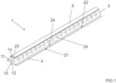
- At least one of the two web plates 5 of the steel beam 1 is preferably, but not necessarily, fastened to the base plate 4 of the steel beam 1 at a distance from an elongated edge 21 of the base plate 4 of the steel beam 1 so that a support flange 22 for at least one building element such a for at least one hollow core slab is formed at the base plate 4 of the steel beam 1 between the elongated edge 21 of the base plate 4 of the steel beam 1 and said at least one of the two web plates 5 of the steel beam 1.
- the possible top plate 6 of the steel beam 1 forms preferably, but not necessarily, in some variants of the steel beam 1, part of the fill space housing 14.
- the fill opening 23 of the fill space housing 14 is preferably, but not necessarily, provided at least partly between the top plate 6 of the steel beam 1 and the end plate 7 of the steel beam 1.
- the fill opening 23 of the fill space housing 14 can alternatively preferably, but not necessarily, be provided at least partly in the top plate 6 of the steel beam 1.
Description
- The invention relates to a steel beam as defined in the preamble of
independent claim 1. - Steel beams to be filled with concrete to form steel-concrete-composite beams are normally on installation first supported on consoles arranged at a building component such as a column so that the console projects into a space of the steel beam via a console supporting slot provided at the end of the steel beam that is supported at the console and thereafter the space of the steel beam is filled i.e. casted with concrete so that the steel beam together with concrete will form a steel-concrete-composite beam. This casting will form a fire protection for the parts of the console in the space inside the steel beam and additionally protect parts such as bolts of the console inside the space of the steel beam from untightening. A problem with this is however that casted concrete will make the parts of the console inside the space of the steel beam inaccessible and this makes it impossible to dismount the steel-concrete-composite beam from the console without damaging the steel-concrete-composite beam.
- Document
KR 101.779.449 B1 claim 1. - The object is to provide a steel beam that can be used to provide a steel-concrete-composite beam that provides for required fire protection of the parts of the console inside the steel beam and that is dismountable from a console of a building so that the steel-concrete-composite beam can be used as a building component at another location in the building or as a building component in another building.
- The steel beam of the invention is characterized by the definitions of
independent claim 1. Preferred embodiments of the steel beam are defined in the dependent claims. - In the following the steel beam will described in more detail by referring to the figures, of which
-
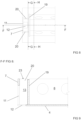
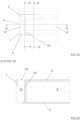
Figure 1 shows a variant of a steel beam, -
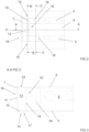
Figure 2 shows in top view an end of a steel beam according to a first embodiment, -
Figure 3 shows the end of the steel beam according to the first embodiment shown infigure 2 as cut along line A-A infigure 2 , -
Figure 4 shows the end of the steel beam according to the first embodiment shown infigure 2 as cut along line B-B infigure 2 , -
Figure 5 shows the end of the steel beam according to the first embodiment shown infigure 2 as cut along line C-C infigure 2 , -
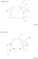
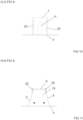
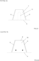
Figure 6 shows as cut along line D-D infigure 6 supporting a steel beam according to the first embodiment on a console provided at a column, -
Figure 7 shows as cut along line E-E infigure 5 supporting a steel beam according to the first embodiment on a console provided at a column, -
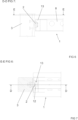
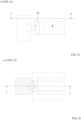
Figure 8 shows in top view an end of a steel beam according to a second embodiment, -
Figure 9 shows the end of the steel beam according to the second embodiment shown infigure 8 as cut along line F-F infigure 8 , -
Figure 10 shows the end of the steel beam according to the second embodiment shown infigure 8 as cut along line G-G infigure 8 , -
Figure 11 shows the end of the steel beam according to the second embodiment shown infigure 8 as cut along line H-H infigure 8 , -
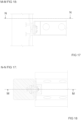
Figure 12 shows as cut along line I-I infigure 13 supporting a steel beam according to the second embodiment on a console provided at a column, -
Figure 13 shows as cut along line J-J infigure 12 supporting a steel beam according to the second embodiment on a console provided at a column, -
Figure 14 shows in top view an end of a steel beam according to a third embodiment, -
Figure 15 shows the end of the steel beam according to the third embodiment shown infigure 7 as cut along line K-K infigure 14 , -
Figure 16 shows the end of the steel beam according to the third embodiment shown infigure 7 as cut along line L-L infigure 14 , -
Figure 17 shows as cut along line M-M infigure 18 supporting a steel beam according to the third embodiment on a console provided at a column, -
Figure 18 shows as cut along line N-N infigure 17 supporting a steel beam according to the third embodiment on a console provided at a column, -
Figure 19 shows in top view an end of a steel beam according to a fourth embodiment, -
Figure 20 shows the end of the steel beam according to the fourth embodiment shown infigure 7 as cut along line O-O infigure 19 , -
Figure 21 shows the end of the steel beam according to the fourth embodiment shown infigure 7 as cut along line P-P infigure 19 , -
Figure 22 shows the end of the steel beam according to the fourth embodiment shown infigure 7 as cut along line Q-Q infigure 19 , -
Figure 23 shows as cut along line R-R infigure 24 supporting a steel beam according to the fourth embodiment on a console provided at a column, -
Figure 24 shows as cut along line S-S infigure 23 supporting a steel beam according to the fourth embodiment on a console provided at a column, -
Figure 25 shows in top view an end of a steel beam according to a fifth embodiment, -
Figure 26 shows the end of the steel beam according to the fourth embodiment shown infigure 7 as cut along line T-T infigure 25 . - In the following some embodiments and variants of the
steel beam 1 will be presented in greater detail. - The figures show some embodiments of the
steel beam 1 and additionally supporting of some embodiments of thesteel beam 1 on aconsole 2 provided at acolumn 3. Theconsole 2 can alternatively be provided at another type of structure in a building that at acolumn 3. The structure in the building can for example be a steel structure, a precast or a cast-in-situ concrete structure, or a steel-concrete-composite structure. - The
steel beam 1 comprises abase plate 4, twoweb plates 5 extending from thebase plate 4, possible atop plate 6 connecting the twoweb plates 5, and anend plate 7 of each end of thesteel beam 1. That thesteel beam 1 comprises possible atop plate 6 means in this connection that thesteel beam 1 can be asteel beam 1 comprising atop plate 6 as is the case in thesteel beams 1 illustrated in the figures or alternatively that thesteel beam 1 can be asteel beam 1 without a top plate so that the steel beam has an open top between theweb plates 5. - The
base plate 4, the twoweb plates 5, the possibletop plate 6 and theend plates 7 delimit aspace 8 configured to be filled at least partly with hardening material such as concrete 9. - At least one of the ends of the
steel beam 1 comprising aconsole supporting slot 10 extending from said at least one end of thesteel beam 1, wherein theconsole supporting slot 10 forms afirst slot 11 in theend plate 7 of thesteel beam 1 and asecond slot 12 in thebase plate 4 of thesteel beam 1. - The
steel beam 1 comprising afill space 13 at at least one of the ends of thesteel beam 1. - The
fill space 13 being limited by afill space housing 14 configured to separate thefill space 13 from thespace 8 of thesteel beam 1. - The
console supporting slot 10 is provided at least partly in thefill space 13 so that theconsole supporting slot 10 is separated from thespace 8 of thesteel beam 1 by thefill space housing 14. - The
fill space housing 14 has in addition to the supporting slot and possible air outlet openings leading out of the fill space a fill opening 23 leading into thefill space 13. - Provision of
such fill space 13 that by means of thefill space housing 14 is separated from thespace 8 of thesteel beam 1 so that theconsole supporting slot 10 of thesteel beam 1 is separated from thespace 8 of thesteel beam 1 by means of thefill space housing 14 makes it possible to fill thefill space 13 of thesteel beam 1 around theconsole supporting slot 10 with a fill material that provides for required fire protection of the parts of the console with are inside thefill space 13 and that is easier to remove than the hardening material such as concrete 9 thespace 8 of thesteel beam 1 is filled with. This makes it possible to remove thesteel beam 1 from aconsole 2 without damaging thesteel beam 1 in such manner that thesteel beam 1 can be reused in another location in the same building or be reused in another building. Lime mortar can for example be used as said fill material. - The
fill space housing 14 comprises preferably, but not necessarily, at least two oppositeside wall structures 15, at least two oppositeend wall structures 16, and abottom structure 17. - If the
fill space housing 14 comprises at least two oppositeside wall structures 15, at least two oppositeend wall structures 16, and abottom structure 17, thebottom structure 17 of thefill space housing 14 is preferably, but not necessarily, formed by thebase plate 4 of thesteel beam 1. - If the
fill space housing 14 comprises at least two oppositeside wall structures 15, at least two oppositeend wall structures 16, and abottom structure 17, one of the oppositeend wall structures 16 of thefill space housing 14 is preferably, but not necessarily, formed by theend plate 7 of thesteel beam 1 comprising thefirst slot 11. - In the first embodiment of the
steel beam 1 illustrated infigures 2 to 5 , thefill space housing 14 comprises two oppositeside wall structures 15, two oppositeend wall structures 16, and abottom structure 17. - In this first embodiment of the
steel beam 1 thebottom structure 17 of thefill space housing 14 is formed by thebase plate 4 of thesteel beam 1. - In this first embodiment of the
steel beam 1 one of the oppositeend wall structures 16 of thefill space housing 14 is formed by theend plate 7 of thesteel beam 1 comprising thefirst slot 11. - In this first embodiment of the
steel beam 1 the oppositeside wall structures 15 of thefill space housing 14 are formed by twoadditional web plates 18, eachadditional web plate 18 extending between one of theweb plates 5. Theadditional web plates 18 provides also for additional strength of thesteel beam 1 at thefill space housing 14. - In this first embodiment of the
steel beam 1 the other of the oppositeend wall structures 16 of thefill space housing 14 is formed by anadditional end plate 19 that is provided separated from theend plate 7 of thesteel beam 1 provided with thefirst slot 11 so that theadditional end plate 19 extend between thetop plate 6 of thesteel beam 1, thebase plate 4 of thesteel beam 1, and theweb plates 5 of thesteel beam 1. -
Figures 6 and 7 shows supporting of thesteel beam 1 according to the first embodiment on aconsole 2 provided at acolumn 3. As can be seen infigures 6 and 7 , theconsole 2 extends into thefill space 13 that is by means of thefill space housing 14 separated from thespace 8 of thesteel beam 1. Provision of thefill space housing 14 allows to fill thefill space 13 and thespace 8 with different materials for example so that thefill space 13 is filled with a material that is easy to remove such as lime mortar, while thespace 8 is filled with concrete. To use easy to remove material in thefill space 13 promotes detaching of thesteel beam 1 from thecolumn 3 and makes it possible to remove thesteel beam 1 from theconsole 2 without damaging thesteel beam 1 in such manner that thesteel beam 1 can be reused in another location in the same building or be reused in another building, because it will be easier to access the part of theconsole 2 that is in thefill space 13 and because the material in thefill space 13 can be removed so that it does not bind thesteel beam 1 to theconsole 2. The material in thefill space 13 will provide for fire protection for a part of thesteel beam 1 and the parts ofconsole 2 inside the fill space and the material in thespace 8 will provide for fire protection for another parts of thesteel beam 1. - In the second embodiment of the
steel beam 1 illustrated infigures 8 to 11 , thefill space housing 14 comprises two oppositeside wall structures 15, two oppositeend wall structures 16, and abottom structure 17. - In this second embodiment of the
steel beam 1 thebottom structure 17 of thefill space housing 14 is formed by thebase plate 4 of thesteel beam 1. - In this second embodiment of the
steel beam 1 one of the oppositeend wall structures 16 of thefill space housing 14 is formed by theend plate 7 of thesteel beam 1 comprising thefirst slot 11. - In this second embodiment of the
steel beam 1 the other of the oppositeend wall structures 16 of thefill space housing 14 is formed by anadditional end plate 19 that is provided separated from theend plate 7 of thesteel beam 1 comprising thefirst slot 11 so that theadditional end plate 19 extend between thetop plate 6 of thesteel beam 1, thebase plate 4 of thesteel beam 1, and theweb plates 5 of thesteel beam 1. - In this second embodiment of the
steel beam 1 the oppositeside wall structures 15 of thefill space housing 14 are formed byopposite side plates 20 extending betweenbase plate 4 of thesteel beam 1, theadditional end plate 19, and theend plate 7 of thesteel beam 1 that is provided with thefirst slot 11. - In this second embodiment of the
steel beam 1 theweb plates 5 of thesteel beam 1 are not directly connected to theend plate 7 of thesteel beam 1 comprising thefirst slot 11, i.e. theweb plates 5 of thesteel beam 1 do not extend to theend plate 7 of thesteel beam 1 comprising thefirst slot 11. -
Figures 12 and 13 shows supporting of thesteel beam 1 according to the second embodiment on aconsole 2 provided at acolumn 3. As can be seen infigures 12 and 13 , theconsole 2 extends into thefill space 13 that is by means of thefill space housing 14 separated from thespace 8 of thesteel beam 1. - In the third embodiment of the
steel beam 1 illustrated infigures 14 to 16 , thefill space housing 14 comprises two oppositeside wall structures 15, two oppositeend wall structures 16, and abottom structure 17. - In this third embodiment of the
steel beam 1 thebottom structure 17 of thefill space housing 14 is formed by thebase plate 4 of thesteel beam 1. - In this third embodiment of the
steel beam 1 one of the oppositeend wall structures 16 of thefill space housing 14 is formed by theend plate 7 of thesteel beam 1 comprising thefirst slot 11. - In this third embodiment of the
steel beam 1 theweb plates 5 of thesteel beam 1 are connected to theend plate 7 of thesteel beam 1 comprising thefirst slot 11. - In this third embodiment of the
steel beam 1 by the other of the oppositeend wall structures 16 of thefill space housing 14 being formed by anadditional end plate 19 that is provided separated from theend plate 7 of thesteel beam 1 comprising thefirst slot 11. - In this third embodiment of the
steel beam 1 the oppositeside wall structures 15 of thefill space housing 14 being formed by twoopposite side plates 20 each extending betweenbase plate 4 of thesteel beam 1, theadditional end plate 19, and theend plate 7 of thesteel beam 1 that is provided with thefirst slot 11. - Because the
additional end plate 19 is not connected to theweb plates 5 of thesteel beam 1 in this third embodiment of thesteel beam 1, concrete to be filled i.e. cast into thespace 8 of thesteel beam 1 can flow between theweb plates 5 of thesteel beam 1 and theopposite side plates 20 to theend plate 7 of thesteel beam 1 comprising thefirst slot 11. Because concrete is stronger than for example lime mortar, this will have a positive impact on the strength of the steel-concrete-composite beam. -
Figures 17 and 18 shows supporting of thesteel beam 1 according to the third embodiment on aconsole 2 provided at acolumn 3. As can be seen infigures 17 and 18 , theconsole 2 extends into thefill space 13 that is by means of thefill space housing 14 separated from thespace 8 of thesteel beam 1. - In the fourth embodiment of the
steel beam 1 illustrated infigures 19 to 22 , thefill space housing 14 comprises two oppositeside wall structures 15, two oppositeend wall structures 16, and abottom structure 17. - In this fourth embodiment of the
steel beam 1 thebottom structure 17 of thefill space housing 14 is formed by thebase plate 4 of thesteel beam 1. - In this fourth embodiment of the
steel beam 1 one of the oppositeend wall structures 16 of thefill space housing 14 is formed by theend plate 7 of thesteel beam 1 comprising thefirst slot 11. - In this fourth embodiment of the
steel beam 1 the oppositeside wall structures 15 of thefill space housing 14 are formed by theweb plates 5 of thesteel beam 1. In this fourth embodiment of thesteel beam 1 theweb plates 5 of thesteel beam 1 extend to theend plate 7 of thesteel beam 1 comprising thefirst slot 11 and theweb plates 5 of thesteel beam 1 are connected to theend plate 7 of thesteel beam 1 comprising thefirst slot 11. - In this fourth embodiment of the
steel beam 1 the other of the oppositeend wall structures 16 of thefill space housing 14 are formed by anadditional end plate 19 that is provided separated from theend plate 7 of thesteel beam 1 comprising thefirst slot 11 to extend between thetop plate 6 of thesteel beam 1, thebase plate 4 of thesteel beam 1, and theweb plates 5 of thesteel beam 1. - If the of the other of the opposite
end wall structures 16 of thefill space housing 14 is formed by anadditional end plate 19 as presented, theadditional end plate 19 can be at least partly curved. - If the opposite side wall structures of the
fill space housing 14 is formed byopposite side plates 20 as presented, theopposite side plates 20 can be at least partly curved - If the other of the opposite
end wall structures 16 of thefill space housing 14 is formed by anadditional end plate 19 as presented and if the opposite side wall structures of thefill space housing 14 is formed byopposite side plates 20 as presented, theadditional end plate 19 can be at least partly curved, and theopposite side plates 20 can be at least partly curved, as in the fifth embodiment of the steel beam illustrated infigures 25 and 26 . In such embodiments of the steel beam it is for example possible that thefill space housing 14 is at least partly formed by using tube that is cut for example in half or in another way in the lengthwise or longitudinal direction of the tube to provide saidadditional end plate 19 and saidopposite side plates 20 of thefill space housing 14. -
Figures 23 and 24 shows supporting of thesteel beam 1 according to the fourth embodiment on aconsole 2 provided at acolumn 3. As can be seen infigures 23 and 24 , theconsole 2 extends into thefill space 13 that is by means of thefill space housing 14 separated from thespace 8 of thesteel beam 1. - The two
web plates 5 of thesteel beam 1 can be inclined in relation to thebase plate 4, and by the twoweb plates 5 of thesteel beam 1 being provided with apertures leading into thespace 8 of thesteel beam 1 for allowing concrete to enter thespace 8 of thesteel beam 1. It is also possible that one of the twoweb plates 5 of thesteel beam 1 extending perpendicularly in relation to thebase plate 4 and being essentially free of apertures, and that the other of the twoweb plates 5 of thesteel beam 1 being inclined in relation to thebase plate 4 and being provided with apertures. Other configurations of theweb plates 5 of thesteel beam 1 are also possible. - At least one of the two
web plates 5 of thesteel beam 1 is preferably, but not necessarily, fastened to thebase plate 4 of thesteel beam 1 at a distance from anelongated edge 21 of thebase plate 4 of thesteel beam 1 so that asupport flange 22 for at least one building element such a for at least one hollow core slab is formed at thebase plate 4 of thesteel beam 1 between theelongated edge 21 of thebase plate 4 of thesteel beam 1 and said at least one of the twoweb plates 5 of thesteel beam 1. - The possible
top plate 6 of thesteel beam 1 forms preferably, but not necessarily, in some variants of thesteel beam 1, part of thefill space housing 14. In such variants of thesteel beam 1, thefill opening 23 of thefill space housing 14 is preferably, but not necessarily, provided at least partly between thetop plate 6 of thesteel beam 1 and theend plate 7 of thesteel beam 1. In such variants of thesteel beam 1, thefill opening 23 of thefill space housing 14 can alternatively preferably, but not necessarily, be provided at least partly in thetop plate 6 of thesteel beam 1. - It is apparent to a person skilled in the art that as technology advances, the basic idea of the invention can be implemented in various ways. The invention and its embodiments are therefore not restricted to the above examples, but they may vary within the scope of the claims.
Claims (18)
- A steel beam (1) comprisinga base plate (4), two web plates (5) extending from the base plate (4), and an end plate (7) of each end of the steel beam (1),wherein the base plate (4), the two web plates (5), the first end plates (7) delimit a space (8) configured to be filled at least partly with hardening material (9) such as concrete, andwherein at least one of the ends of the steel beam (1) comprising a console supporting slot (10) extending from said at least one end of the steel beam (1), wherein the console supporting slot (10) forms a first slot (11) in the end plate (7) of the steel beam (1) and a second slot (12) in the base plate (4) of the steel beam (1),wherein the steel beam (1) comprises a fill space (13) at at least one of the ends of the steel beam (1),wherein the fill space (13) is limited by a fill space housing (14) configured to separate the fill space (13) from the space (8) of the steel beam (1),wherein the fill space housing (14) has in addition to the console supporting slot (10) and possible air outlet openings leading out of the fill space (13) a fill opening (23) leading into the fill space (13),characterizedby the console supporting slot (10) being provided at least partly in the fill space so that the console supporting slot being separated from the space of the steel beam by the fill space housing.
- The steel beam (1) according to claim 1, characterized
by the fill space housing (14) comprising at least two opposite side wall structures (15), at least two opposite end wall structures (16), and a bottom structure (17). - The steel beam (1) according to claim 2, characterized
by the bottom structure (17) of the fill space housing (14) being formed by the base plate (4) of the steel beam (1). - The steel beam (1) according to claim 2 or 3, characterized
by one of the opposite end wall structures (16) of the fill space housing (14) being formed by the end plate (7) of the steel beam (1) comprising the first slot (11). - The steel beam (1) according to claim 4, characterizedby the opposite side wall structures (15) of the fill space housing (14) being formed by additional web plates (18),by each additional web plate (18) extending between one of the web plates (5) of the steel beam (1) and the end plate (7) of the steel beam (1) that is provided with the first slot (11),by the other of the opposite end wall structures (16) of the fill space housing (14) being formed by an additional end plate (19) that is provided separated from the end plate (7) of the steel beam (1) comprising the first slot (11), andby the additional end plate (19) extend between the base plate (4) of the steel beam (1), and the web plates (5) of the steel beam (1).
- The steel beam (1) according to claim 4, characterizedby the opposite side wall structures (15) of the fill space housing (14) being formed by the web plates (5) of the steel beam (1),by the web plates (5) of the steel beam (1) being connected to the end plate (7) of the steel beam (1) comprising the first slot (11),by the other of the opposite end wall structures (16) of the fill space housing (14) being formed by an additional end plate (19) that is provided separated from the end plate (7) of the steel beam (1) comprising the first slot (11), andby the additional end plate (19) extend between the base plate (4) of the steel beam (1), and the web plates (5) of the steel beam (1).
- The steel beam (1) according to claim 4, characterizedby the other of the opposite end wall structures (16) of the fill space housing (14) being formed by an additional end plate (19) that is provided separated from the end plate (7) of the steel beam (1) comprising the first slot (11),by the additional end plate (19) extend between the base plate (4) of the steel beam (1), and the web plates (5) of the steel beam (1), andby the opposite side wall structures (15) of the fill space housing (14) being formed by opposite side plates (20) extending between base plate (4) of the steel beam (1), the additional end plate (19), and the end plate (7) of the steel beam (1) that is provided with the first slot (11).
- The steel beam (1) according to claim 4, characterizedby the web plates (5) of the steel beam (1) being connected to the end plate (7) of the steel beam (1) comprising the first slot (11),by the other of the opposite end wall structures (16) of the fill space housing (14) being formed by an additional end plate (19) that is provided separated from the end plate (7) of the steel beam (1) comprising the first slot (11), andby the opposite side wall structures (15) of the fill space housing (14) being formed by opposite side plates (20) extending between base plate (4) of the steel beam (1), the additional end plate (19), and the end plate (7) of the steel beam (1) that is provided with the first slot (11).
- The steel beam according to any of the claims 5 to 8, characterized
by the additional end plate (19) being at least partly curved. - The steel beam according to claim 7 or 8, characterized
by the opposite side plates (20) being at least partly curved. - The steel beam according to claim 7 or 8, characterizedby the additional end plate (19) being at least partly curved, andby the opposite side plates (20) being at least partly curved.
- The steel beam (1) according to any of the claims 1 to 11, characterizedby the two web plates (5) of the steel beam (1) being inclined in relation to the base plate (4), andby the two web plates (5) of the steel beam (1) being provided with apertures.
- The steel beam (1) according to any of the claims 1 to 11, characterizedby one of the two web plates (5) of the steel beam (1) extending perpendicularly in relation to the base plate (4) and being free of apertures, andby the other of the two web plates (5) of the steel beam (1) being inclined in relation to the base plate (4) and being provided with apertures.
- The steel beam (1) according to any of the claims 1 to 13, characterized
by at least one of the two web plates (5) of the steel beam (1) being fastened to the base plate (4) of the steel beam (1) at a distance from an elongated edge (21) of the base plate (4) of the steel beam (1) so that a support flange (22) is formed at the base plate (4) of the steel beam (1) between the elongated edge (21) of the base plate (4) of the steel beam (1) and said at least one of the two web plates (5) of the steel beam (1). - The steel beam (1) according to any of the claims 1 to 14, characterizedby a top plate (6) connecting the two web plates (5), andby the top plate (6) at least partly limiting the space (8) of the steel beam (1).
- The steel beam (1) according to claim 15, characterized
by the top plate (6) of the steel beam (1) forming a part of the fill space housing (14). - The steel beam (1) according claim 16, characterized
by the fill opening (23) of the fill space housing (14) being provided at least partly between the top plate (6) of the steel beam (1) and the end plate (7) of the steel beam (1). - The steel beam (1) according to any of the claims 15 to 17, characterized
by the fill opening (23) of the fill space housing (14) being provided at least partly in the top plate (6) of the steel beam (1).
Applications Claiming Priority (2)
| Application Number | Priority Date | Filing Date | Title |
|---|---|---|---|
| FI20205414 | 2020-04-24 | ||
| PCT/FI2021/050267 WO2021214381A1 (en) | 2020-04-24 | 2021-04-14 | Steel beam |
Publications (3)
| Publication Number | Publication Date |
|---|---|
| EP4139532A1 EP4139532A1 (en) | 2023-03-01 |
| EP4139532B1 true EP4139532B1 (en) | 2024-03-06 |
| EP4139532C0 EP4139532C0 (en) | 2024-03-06 |
Family
ID=75625607
Family Applications (1)
| Application Number | Title | Priority Date | Filing Date |
|---|---|---|---|
| EP21720552.5A Active EP4139532B1 (en) | 2020-04-24 | 2021-04-14 | Steel beam |
Country Status (3)
| Country | Link |
|---|---|
| EP (1) | EP4139532B1 (en) |
| CA (1) | CA3177551A1 (en) |
| WO (1) | WO2021214381A1 (en) |
Family Cites Families (4)
| Publication number | Priority date | Publication date | Assignee | Title |
|---|---|---|---|---|
| NL1003454C2 (en) * | 1996-06-28 | 1998-01-07 | Gruenbauer G C Bv | Beam and method and device for installing a beam. |
| NL1020608C2 (en) * | 2002-05-16 | 2003-11-18 | Constructiewerkplaats G C Gr N | System incorporates at least steel girders, particularly for use in steel and/or concrete skeletal structures |
| FI20021744A (en) * | 2002-10-01 | 2004-04-02 | Teraespeikko Oy | Arrangement for forming a joint between a beam and a bracket to support a building part such as a concrete element at a concrete pillar or the corresponding supporting structure of a building |
| KR101779449B1 (en) * | 2017-03-14 | 2017-09-18 | 우경기술주식회사 | A hollow box type steel built up beam and construction method using the same |
-
2021
- 2021-04-14 EP EP21720552.5A patent/EP4139532B1/en active Active
- 2021-04-14 CA CA3177551A patent/CA3177551A1/en active Pending
- 2021-04-14 WO PCT/FI2021/050267 patent/WO2021214381A1/en active Search and Examination
Also Published As
| Publication number | Publication date |
|---|---|
| EP4139532A1 (en) | 2023-03-01 |
| WO2021214381A1 (en) | 2021-10-28 |
| EP4139532C0 (en) | 2024-03-06 |
| CA3177551A1 (en) | 2021-10-28 |
Similar Documents
| Publication | Publication Date | Title |
|---|---|---|
| US7493735B2 (en) | Spiral stirrup and steel element combination structure system | |
| FI85745C (en) | Fireproof prefabricated steel beam | |
| JP2006322182A (en) | Corrugated steel web bridge | |
| EP4139532B1 (en) | Steel beam | |
| US6158189A (en) | Wooden I-beam and wooden structural beam and bridging assembly | |
| JP2002146721A (en) | Precast wall balustrade installation method | |
| KR101012010B1 (en) | Built-up Beam having Profiled Steel Web | |
| US20100301190A1 (en) | Modular edge form system for cast in place suspended concrete slabs | |
| US3977647A (en) | Means for connecting abutting form panels and for mounting a tie rod | |
| KR102300598B1 (en) | Wind duct slab unit including a hollow forming unit and a method for constructing the wind duct slab using the same | |
| EP0555232B1 (en) | Connector beam | |
| EP2463457A1 (en) | High-precision integral modular formwork system for the construction of monolithic reinforced-concrete structures | |
| KR20230034002A (en) | Bridge support integrated cantilever structure and its construction method | |
| JP4096534B2 (en) | Bridge using external cable | |
| JP3587582B2 (en) | Segment for tunnel | |
| EP1630349B1 (en) | Intermediate ceiling for a tunnel and method for its construction | |
| JP4568657B2 (en) | Steel synthetic concrete precast slab | |
| KR102068307B1 (en) | Double composite steel box girder using t-conner reinforcing member and construction method therewith | |
| JPH08144414A (en) | Hollow concrete slab method and hollow concrete slab | |
| CN213978593U (en) | Assembled track roof beam | |
| JP2509077B2 (en) | Rainwater underground storage facility | |
| KR102284778B1 (en) | Wide lightweight PC girder | |
| KR102318867B1 (en) | Bracing composite precast deckplate and Slab construction method using it | |
| RU56911U1 (en) | STRIP FOR STRUCTURAL FORMWORK | |
| RU2306391C1 (en) | Retained form tie |
Legal Events
| Date | Code | Title | Description |
|---|---|---|---|
| STAA | Information on the status of an ep patent application or granted ep patent |
Free format text: STATUS: UNKNOWN |
|
| STAA | Information on the status of an ep patent application or granted ep patent |
Free format text: STATUS: THE INTERNATIONAL PUBLICATION HAS BEEN MADE |
|
| PUAI | Public reference made under article 153(3) epc to a published international application that has entered the european phase |
Free format text: ORIGINAL CODE: 0009012 |
|
| STAA | Information on the status of an ep patent application or granted ep patent |
Free format text: STATUS: REQUEST FOR EXAMINATION WAS MADE |
|
| 17P | Request for examination filed |
Effective date: 20221122 |
|
| AK | Designated contracting states |
Kind code of ref document: A1 Designated state(s): AL AT BE BG CH CY CZ DE DK EE ES FI FR GB GR HR HU IE IS IT LI LT LU LV MC MK MT NL NO PL PT RO RS SE SI SK SM TR |
|
| DAV | Request for validation of the european patent (deleted) | ||
| DAX | Request for extension of the european patent (deleted) | ||
| GRAP | Despatch of communication of intention to grant a patent |
Free format text: ORIGINAL CODE: EPIDOSNIGR1 |
|
| STAA | Information on the status of an ep patent application or granted ep patent |
Free format text: STATUS: GRANT OF PATENT IS INTENDED |
|
| INTG | Intention to grant announced |
Effective date: 20231123 |
|
| GRAS | Grant fee paid |
Free format text: ORIGINAL CODE: EPIDOSNIGR3 |
|
| GRAA | (expected) grant |
Free format text: ORIGINAL CODE: 0009210 |
|
| STAA | Information on the status of an ep patent application or granted ep patent |
Free format text: STATUS: THE PATENT HAS BEEN GRANTED |
|
| AK | Designated contracting states |
Kind code of ref document: B1 Designated state(s): AL AT BE BG CH CY CZ DE DK EE ES FI FR GB GR HR HU IE IS IT LI LT LU LV MC MK MT NL NO PL PT RO RS SE SI SK SM TR |
|
| REG | Reference to a national code |
Ref country code: CH Ref legal event code: EP |
|
| REG | Reference to a national code |
Ref country code: DE Ref legal event code: R096 Ref document number: 602021010157 Country of ref document: DE |
|
| REG | Reference to a national code |
Ref country code: IE Ref legal event code: FG4D |
|
| U01 | Request for unitary effect filed |
Effective date: 20240404 |