EP4138666B1 - Elektrodenvorrichtung für amplitudenintegrierte elektroenzephalographie - Google Patents
Elektrodenvorrichtung für amplitudenintegrierte elektroenzephalographie Download PDFInfo
- Publication number
- EP4138666B1 EP4138666B1 EP21718605.5A EP21718605A EP4138666B1 EP 4138666 B1 EP4138666 B1 EP 4138666B1 EP 21718605 A EP21718605 A EP 21718605A EP 4138666 B1 EP4138666 B1 EP 4138666B1
- Authority
- EP
- European Patent Office
- Prior art keywords
- electrode device
- electrode
- protruding part
- housing
- previous
- Prior art date
- Legal status (The legal status is an assumption and is not a legal conclusion. Google has not performed a legal analysis and makes no representation as to the accuracy of the status listed.)
- Active
Links
Images


Classifications
-
- A—HUMAN NECESSITIES
- A61—MEDICAL OR VETERINARY SCIENCE; HYGIENE
- A61B—DIAGNOSIS; SURGERY; IDENTIFICATION
- A61B5/00—Measuring for diagnostic purposes; Identification of persons
- A61B5/24—Detecting, measuring or recording bioelectric or biomagnetic signals of the body or parts thereof
- A61B5/25—Bioelectric electrodes therefor
- A61B5/251—Means for maintaining electrode contact with the body
- A61B5/257—Means for maintaining electrode contact with the body using adhesive means, e.g. adhesive pads or tapes
-
- A—HUMAN NECESSITIES
- A61—MEDICAL OR VETERINARY SCIENCE; HYGIENE
- A61B—DIAGNOSIS; SURGERY; IDENTIFICATION
- A61B5/00—Measuring for diagnostic purposes; Identification of persons
- A61B5/24—Detecting, measuring or recording bioelectric or biomagnetic signals of the body or parts thereof
- A61B5/25—Bioelectric electrodes therefor
- A61B5/263—Bioelectric electrodes therefor characterised by the electrode materials
- A61B5/265—Bioelectric electrodes therefor characterised by the electrode materials containing silver or silver chloride
-
- A—HUMAN NECESSITIES
- A61—MEDICAL OR VETERINARY SCIENCE; HYGIENE
- A61B—DIAGNOSIS; SURGERY; IDENTIFICATION
- A61B5/00—Measuring for diagnostic purposes; Identification of persons
- A61B5/24—Detecting, measuring or recording bioelectric or biomagnetic signals of the body or parts thereof
- A61B5/25—Bioelectric electrodes therefor
- A61B5/263—Bioelectric electrodes therefor characterised by the electrode materials
- A61B5/266—Bioelectric electrodes therefor characterised by the electrode materials containing electrolytes, conductive gels or pastes
-
- A—HUMAN NECESSITIES
- A61—MEDICAL OR VETERINARY SCIENCE; HYGIENE
- A61B—DIAGNOSIS; SURGERY; IDENTIFICATION
- A61B5/00—Measuring for diagnostic purposes; Identification of persons
- A61B5/24—Detecting, measuring or recording bioelectric or biomagnetic signals of the body or parts thereof
- A61B5/25—Bioelectric electrodes therefor
- A61B5/263—Bioelectric electrodes therefor characterised by the electrode materials
- A61B5/268—Bioelectric electrodes therefor characterised by the electrode materials containing conductive polymers, e.g. PEDOT:PSS polymers
-
- A—HUMAN NECESSITIES
- A61—MEDICAL OR VETERINARY SCIENCE; HYGIENE
- A61B—DIAGNOSIS; SURGERY; IDENTIFICATION
- A61B5/00—Measuring for diagnostic purposes; Identification of persons
- A61B5/24—Detecting, measuring or recording bioelectric or biomagnetic signals of the body or parts thereof
- A61B5/25—Bioelectric electrodes therefor
- A61B5/279—Bioelectric electrodes therefor specially adapted for particular uses
- A61B5/291—Bioelectric electrodes therefor specially adapted for particular uses for electroencephalography [EEG]
-
- A—HUMAN NECESSITIES
- A61—MEDICAL OR VETERINARY SCIENCE; HYGIENE
- A61B—DIAGNOSIS; SURGERY; IDENTIFICATION
- A61B5/00—Measuring for diagnostic purposes; Identification of persons
- A61B5/68—Arrangements of detecting, measuring or recording means, e.g. sensors, in relation to patient
- A61B5/6801—Arrangements of detecting, measuring or recording means, e.g. sensors, in relation to patient specially adapted to be attached to or worn on the body surface
- A61B5/683—Means for maintaining contact with the body
- A61B5/6832—Means for maintaining contact with the body using adhesives
-
- A—HUMAN NECESSITIES
- A61—MEDICAL OR VETERINARY SCIENCE; HYGIENE
- A61B—DIAGNOSIS; SURGERY; IDENTIFICATION
- A61B2503/00—Evaluating a particular growth phase or type of persons or animals
- A61B2503/04—Babies, e.g. for SIDS detection
-
- A—HUMAN NECESSITIES
- A61—MEDICAL OR VETERINARY SCIENCE; HYGIENE
- A61B—DIAGNOSIS; SURGERY; IDENTIFICATION
- A61B2503/00—Evaluating a particular growth phase or type of persons or animals
- A61B2503/04—Babies, e.g. for SIDS detection
- A61B2503/045—Newborns, e.g. premature baby monitoring
-
- A—HUMAN NECESSITIES
- A61—MEDICAL OR VETERINARY SCIENCE; HYGIENE
- A61B—DIAGNOSIS; SURGERY; IDENTIFICATION
- A61B2505/00—Evaluating, monitoring or diagnosing in the context of a particular type of medical care
- A61B2505/03—Intensive care
-
- A—HUMAN NECESSITIES
- A61—MEDICAL OR VETERINARY SCIENCE; HYGIENE
- A61B—DIAGNOSIS; SURGERY; IDENTIFICATION
- A61B2562/00—Details of sensors; Constructional details of sensor housings or probes; Accessories for sensors
- A61B2562/02—Details of sensors specially adapted for in-vivo measurements
- A61B2562/0209—Special features of electrodes classified in A61B5/24, A61B5/25, A61B5/283, A61B5/291, A61B5/296, A61B5/053
- A61B2562/0215—Silver or silver chloride containing
-
- A—HUMAN NECESSITIES
- A61—MEDICAL OR VETERINARY SCIENCE; HYGIENE
- A61B—DIAGNOSIS; SURGERY; IDENTIFICATION
- A61B2562/00—Details of sensors; Constructional details of sensor housings or probes; Accessories for sensors
- A61B2562/02—Details of sensors specially adapted for in-vivo measurements
- A61B2562/0209—Special features of electrodes classified in A61B5/24, A61B5/25, A61B5/283, A61B5/291, A61B5/296, A61B5/053
- A61B2562/0217—Electrolyte containing
-
- A—HUMAN NECESSITIES
- A61—MEDICAL OR VETERINARY SCIENCE; HYGIENE
- A61B—DIAGNOSIS; SURGERY; IDENTIFICATION
- A61B5/00—Measuring for diagnostic purposes; Identification of persons
- A61B5/68—Arrangements of detecting, measuring or recording means, e.g. sensors, in relation to patient
- A61B5/6801—Arrangements of detecting, measuring or recording means, e.g. sensors, in relation to patient specially adapted to be attached to or worn on the body surface
- A61B5/6813—Specially adapted to be attached to a specific body part
- A61B5/6814—Head
Definitions
- the present invention is directed, in general, to the field of medical electrodes.
- the invention relates to an electrode device designed to record superficial brain bioelectric activity during long periods of time from infants in the neonatal intensive care units (NICU's).
- the electrode is particularly designed to be used in amplitude-integrated electroencephalography (aEEG), however it can also be used to record other long-term neurophysiological recording tests such as continuous electroencephalography monitoring (CEEG), among others.
- aEEG amplitude-integrated electroencephalography
- CEEG continuous electroencephalography monitoring
- aEEG Amplitude-integrated electroencephalography
- aEEG is an easily accessible technique for monitoring the brain function in infants.
- aEEG is a processed single-channel electroencephalogram that is filtered, rectified, enlarged with a semilogarithmic scale and time compressed.
- infant aEEG in the NICUs there are several specific technical aspects for infant aEEG in the NICUs to be considered, beginning with the montage and electrode placement, the long-term recordings (several days or weeks), the lying position of the infants in the NICUs, the frequent manipulation by healthcare staff, the characteristic morphology of the head and the fragility of the scalp of preterm and term infants.
- the known or commercial electrodes do not fulfill the requirements needed for infants and present artifacts in the electrical neuroactivity readings. For infants in a critical situation puts risk relevant clinical decisions.
- the available surface electrodes are not properly sized for term and preterm infant's application. Also, they are usually attached to a long wire that connects them to the bioelectric signal amplifier. This long wire electrode hinders the manipulation of the newborn by health care staff. In addition, the electrode wire is usually attached to the electrode laterally. In the lying patient, the usual position in the NICU's, this joint causes a lever force that facilitates the electrode decoupling.
- Superficial cup electrodes available have a hole through which the electroconductive gel is replaced in order to maintain its high conductive capacity during long-term recordings.
- a blunt-tipped syringe is usually used to remove the old electroconductive gel and apply the new one.
- This pressure can cause an involuntary contact with the scalp surface, which should be avoided in newborns due to their fragility and proximity to the fontanelles.
- its rigid consistency gold or silver electrodes
- the electrodes cover the recording site not offering the opportunity to check the skin of the newborn without detach the electrode.
- Disposable adhesive electrodes have the disadvantage of not allowing the replacement of the electroconductive gel and therefore they must be replaced periodically. This involves more manipulation and possible changes in the recording conditions (placement, impedance, etc.), in a situation where a constant monitorization without cuts is a key element.
- the subdermal needle electrodes which are often used in the aEEG to achieve low impedance recordings have the disadvantage of producing pain. Pain should always be avoided to improve comfort but in the aEEG it also has the disadvantage of not allowing the accurate assessment of a parameter as important as the latency of onset of the sleep-wake cycle.
- the subdermal electrodes have the same drawbacks as most surface electrodes available: are connected to a long wire to the amplifier and are easily detached.
- FR2400370 discloses an electrode device intended to be applied to the skin, for electro-medical purposes.
- the electrode device can be used for electroencephalography, electrocardiography and electromyography.
- the electrode comprises a plastics body with a ring-shaped surface that is stuck to the skin by a double-sided tape.
- An electrode is arranged in a cavity that can be filled with a conductive paste or gel through a hole.
- the hole is arranged on the axis of the electrode body.
- At least one discharge duct from the cavity is provided for excess paste or gel, preferably in the form of a groove in the electrode body under the adhesive tape.
- This electrode has the disadvantage of having the long cable making it difficult for the healthcare staff to handle the child.
- the connection between the plate and the cable is lateral, facilitating the uncoupling of the electrode by lever forces in the lying patient.
- this type of electrode device does not avoid the possible contact with the scalp during the replacement of electroconductive gel.
- US 4657023-A provides a self-adhering electrode for application on the skin of a patient in which a portion of the electrically conductive layer forms an electrode that is substantially surrounded by a pressure-sensitive layer and the remainder of the conductive layer is covered by a substrate which is also conductive and sufficiently pliant to permit the electrode to adjust to the body contour.
- This electrode does not allow electrode conductive gel replacement without removing the electrode. It has a long wire laterally connected that complicates the manipulation of the infant and facilitates the uncoupling of the electrode by lever forces in the lying patient.
- US 4029086-A provides an electrode arrangement which provides for a reliable electrical contact with the skin of a person or animal.
- the electrode arrangement comprises, in combination, a central post with a base flange, an adhesive pad having a central aperture for receiving the central post, a gel member and a resilient o-ring shaped member.
- An alternate embodiment comprises a central post and base flange, an adhesive pad having a central aperture for receiving the central post, and a shield washer, with a central aperture for receiving the central post, mounted above the adhesive pad. Both embodiments minimize the effect of physical forces placed on the electrical contact.
- This electrode has the same disadvantages as US 4657023-A .
- the receptacle Upon completion of filling, the receptacle self-seals, retaining the fluid contents therein for application of iontophoresis treatment or other procedures requiring use of a potential gradient.
- An electrode plate is supported at an interior surface of the receptacle for supplying the desired electric potential.
- This bioelectrode does not have a first protruding part arranged inclined at an angle between 50-80o with respect to the contact surface of the bioelectrode (i.e. the surface of the bioelectrode contacting the skin surface of the patient).
- the electrode device comprises a housing fixed on an adhesive element to adhere the electrode device to the skin surface of a patient, particularly the scalp; an electrode plate placed in the housing at a certain distance from a support surface of the housing forming a hollow space; and a wire connection for the electrode.
- the proposed electrode device has a size and form adaptable to the head of a newborn. It is connected with a short wire that, once disconnected from an amplifier, facilitates the manipulation of the infant by the healthcare staff.
- the vertical orientation of the insertion between the electrode plate and the wire improves stability in the lying position.
- the conical hole prevents accidental contact of a blunt tip of a needle with the infant's scalp and allows the safe replacement of the electroconductive gel, thus facilitating the good signal quality during long-term recordings.
- by being a surface electrode it does not cause discomfort to the patient.
- the electrode plate comprises a first gap which allows the electroconductive gel to flow through and a second gap to fix the rotating position of the electrode plate to the housing using a clamping element. Hence the distance between the skin surface and the electrode plate is reduced (i.e. the mentioned hollow space is smaller).
- the first protruding part is disposed at a 60-degree angle with respect to the contact surface of the electrode device.
- the electrode besides being fully MRI-compatible can be also radiolucent.
- the wire is preferably made of one or more carbon fibers.
- the adhesive element is a flexible adhesive pad including an adhesive layer provided on a lower or bottom surface of the adhesive element.
- the adhesive element comprises a double-sided tape.
- the length of the wire connection is less than 50 millimeters, particularly of approximately 30 millimeters. In other embodiments, the length of the wire connection is between 50 millimeters and 600 millimeters, preferably 100 millimeters. In yet other embodiments, the length of the wire connection can be between 0.6 and 2 meters.
- the wire connection can have a spiral/curved shape in order to have an elastic behavior that will absorb some axial force from the wires of a bioelectric signal amplifier.
- the wire connection can also include an insulating layer, for example made of a material comprising silicone, Polyvinyl chloride, Polypropylene, Polyethylene, XLPE (Cross-Linked Polyethylene), EPR (Ethylene Propylene Rubber), ECTFE (ethylene chlorotrifluoroethylene), PVDF (Polyvinylidene fluoride), Nylon, CPE (Chlorinated polyethylene), etc.
- an insulating layer for example made of a material comprising silicone, Polyvinyl chloride, Polypropylene, Polyethylene, XLPE (Cross-Linked Polyethylene), EPR (Ethylene Propylene Rubber), ECTFE (ethylene chlorotrifluoroethylene), PVDF (Polyvinylidene fluoride), Nylon, CPE (Chlorinated polyethylene), etc.
- one or more sealing elements can be disposed between the housing and the insulating layer of the wire connection and/or over the housing and the first protruding part/first hole.
- the surface of the housing in contact with the adhesive element has a curvature that better fits with the skull shape.
- the electrode plate support surface is formed by several supports that sustain the electrode plate horizontally disposed (i.e. parallel or substantially parallel to the skin surface of the patient).
- the electrode device also includes an encapsulating/isolation element positioned on top of the electrode plate. The encapsulating element prevents the gel from contacting the wire connection, thus avoiding galvanic corrosion.
- the electrode device comprises a third protruding part that is symmetrically arranged with regard to the first protruding part.
- the third protruding part has also a conical-shaped hole particularly for replacing the electroconductive gel present in the hollow space.
- the proposed electrode device allows an easy electrode placement as well as a wire cable extension that permits an easier electrical connection.
- the electrode device design also allows the patient, in particular newborns, to rotate the head without difficulties.
- the new design allows replacing the electroconductive gel for long-term aEEG recordings.
- the electrode device 1 of this embodiment includes a housing 10, for example made of a polymeric, ceramic or metallic material, which is mounted or arranged on a flexible adhesive pad 13A to adhere the electrode device 1 to a skin surface of a patient.
- the flexible adhesive pad 13A has an adhesive layer provided on a lower/bottom surface thereof to allow said adhesion of the electrode device 1 to the skin surface. As seen in the figures, the flexible adhesive pad 13A has a larger diameter than the housing 10.
- the electrode device 1 also includes an electrode plate 11 horizontally disposed (i.e. parallel or substantially parallel to the skin surface of the patient) inside the housing 10 at a certain distance therein forming a hollow space 19.
- the electrode plate 11 is made of, or comprises a coating made of, Silver (Ag), Gold (Au), or Silver/Silver-Chloride (Ag/AgCI). In other embodiments however any other good electrical conductor material such as Tin, Stainless Steel, Platinum, Cooper, Lead, or Nichrome, among others, can be used.
- the electrode device 1 is fully MRI-compatible and/or radiolucent. In this case, conductive and non-magnetic materials should be used for the electrode plate 11 and/or wire connection 12.
- the electrode device 1 includes a flexible wire connection 12 for the electrode plate 11.
- the wire connection 12 is fixed to the electrode plate 11 by one of its extremes using at least one welding point, the other extreme being attached to a touchproof connector 14.
- the connector used can be of different type, for example a male snap connector, among others.
- an adhesive element comprising a double-sided tape 13B (see Fig. 3 and Figs. 4A and 4B for example) can be used instead of the flexible adhesive pad 13A.
- the adhesive element comprises a hydrocolloid adhesive; thus the electrode device 1 is for single-patient use and it is disposable.
- the housing 10 is translucent and flexible.
- skin check irrigation
- gel check from drying or spilling
- electrode plate check from movements or change in color for checking the Ag/AgCI coating, corrosion
- the housing 10 has two protruding parts 16, 17.
- the first protruding part 16 is located inclined outwardly at an angle of approximately 60o-65o with regard to the longitudinal direction of the skin surface (or with regard to the contact surface of the electrode device 1). It should be noted that in other embodiments, in this case not illustrated, the first protruding part 16 can be located at an angle between 50o and 80o with respect to the contact surface of the electrode device 1.
- the first protruding part 16 includes a conical-shaped hole 15 to allow the injection and removal of an electroconductive gel or hydrogel.
- the second protruding part 17 is located about the axis of the housing 10 and includes a second hole for the upright introduction of the wire connection 12.
- Any biocompatible electroconductive gel can be used in accordance with the present disclosure.
- the electroconductive gel can be replaced via a blunt needle through the conical-shaped hole 15 but the needle is blocked by the geometry of the hole to avoid skin injuries.
- the electrode device 1 of Figs. 1A-1C also includes an insulting layer 18 surrounding the wire connection.
- insulting layer 18 can be used as insulating layer for example silicone, Polyvinyl chloride, Polyethylene, Polyvinylidene fluoride and/or Polypropylene, among others.
- FIGs. 2A-2C therein another electrode device 1 is illustrated.
- the hollow space 19 is reduced since the electrode plate 11 is pierced in two parts: one opening 20 is disposed to fit with the conical-shaped hole 15 to allow the electroconductive gel to flow through; the other opening (not seen in the figures) is used for the fixation of the electrode plate 11 to the housing 10, for example via a clamping or fixing element.
- Fig. 3 illustrates an example in which a bottom surface 10C of the housing 10 that contacts the adhesive element comprises a curvature to better fit with the skull.
- the size of the housing 10 in this case is reduced.
- the adhesive element comprises a double-sided tape 13B.
- Figs. 4A and 4B illustrate another example in which the bottom surface 10C of the housing 10 is curved.
- the adhesive element comprises a double-sided tape 13B and the electrode plate 11 is not pierced.
- sealing elements can be also disposed between the housing 10 and the insulating layer 18 of the wire connection 12.
- the first protruding part 16 can comprise a plug for closure thereof.
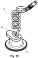
- the wire connection 12 has a curved/spiral shape and the support surface comprises a plurality of supporting structures (or simply supports) 21 that hold the electrode plate 11.
- the electrode device 1 (see the two different sections of Figs. 5A and 5B ) also has an encapsulating element 22 positioned on top of the electrode plate 11 that isolates the wire-plate connection for the electroconductive gel.
- a gap 24 between the encapsulating element 22 and the housing 10 allows the electroconductive gel to flow from the hollow space 19 between the electrode plate 11 and the skin to the second protruding part 17.
- a sealing element 23 is also included covering an upper part of the housing 10 and the first hole 15, such that drying of the gel is reduced. To replace the electroconductive gel, the sealing element 23 has to be lifted to release the first protruding part 16 to insert a blunt needle and to visually check the drain of the gel through the second protruding part 17.
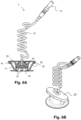
- Figs. 6A and 6B illustrate an embodiment of the proposed electrode device 1 according to the invention.
- the electrode device 1 of this embodiment is similar to the electrode device 1 of previous figures 5A-5C but in this case the housing 10 besides the two protruding parts 16, 17 described above further has a (third) protruding part 25, which is symmetric to the protruding part 16.
- the protruding part 25 also includes a conical-shaped hole 26.
- the third protruding part 25 allows an easier replacement of the electroconductive gel in case the viscosity of the gel is too low, the gel used dries fast or in case the gel only remains in the bottom surface of the electrode plate 11.
- a blunt needle can be inserted in the first 16 or third 25 protruding part and drained by the other one.
- the term "about” and/or “substantially”, when referring to a value or to feature, are meant to encompass variations of in some examples ⁇ 10%, in some examples ⁇ 5%, from the specified value or feature, as such variations are appropriate to perform the disclosed device.
Landscapes
- Life Sciences & Earth Sciences (AREA)
- Health & Medical Sciences (AREA)
- Medical Informatics (AREA)
- Animal Behavior & Ethology (AREA)
- Pathology (AREA)
- Engineering & Computer Science (AREA)
- Biomedical Technology (AREA)
- Heart & Thoracic Surgery (AREA)
- Physics & Mathematics (AREA)
- Molecular Biology (AREA)
- Surgery (AREA)
- Biophysics (AREA)
- General Health & Medical Sciences (AREA)
- Public Health (AREA)
- Veterinary Medicine (AREA)
- Electrotherapy Devices (AREA)
- Measurement And Recording Of Electrical Phenomena And Electrical Characteristics Of The Living Body (AREA)
- Electrodes Of Semiconductors (AREA)
- Semiconductor Integrated Circuits (AREA)
Claims (14)
- Elektrodenvorrichtung für eine amplitudenintegrierte Elektroenzephalographie (aEEG), die umfasst:ein Gehäuse (10), das an einem Haftelement (13A, 13B) angebracht ist, um die Elektrodenvorrichtung (1) an einer Hautoberfläche eines Patienten anzuhaften;eine Elektrodenplatte (11), die in dem Gehäuse (10) in einem gewissen Abstand zu einer Trägerfläche des Gehäuses (10) platziert ist, wobei ein Hohlraum (19) gebildet wird;eine Drahtverbindung (12) für die Elektrodenplatte (11), wobei die Drahtverbindung (12) eine bestimmte Länge aufweist und ein proximales Ende und ein distales Ende umfasst;das Gehäuse (10) einen ersten vorstehenden Teil (16) und einen zweiten vorstehenden Teil (17) umfasst, wobei der erste vorstehende Teil (16) ein erstes Loch (15) aufweist und der zweite vorstehende Teil (17) ein zweites Loch aufweist, durch das das proximale Ende der Drahtverbindung (12) eingeführt und an der Elektrodenplatte (11) befestigt wird, wobei der zweite vorstehende Teil (17) auf der Achse des Gehäuses (10) angeordnet ist,wobei:die Vorrichtung ferner einen dritten vorstehenden Teil (25) umfasst, der in Bezug auf den ersten vorstehenden Teil (16) symmetrisch angeordnet ist; undder erste vorstehende Teil (16) in dem Gehäuse (10) in einem Winkel zwischen 50 Grad und 80 Grad in Bezug auf eine Kontaktfläche der Elektrodenvorrichtung nach außen geneigt angeordnet ist, wobei das erste Loch (15) eine konisch geformte Geometrie aufweist und dazu ausgestaltet ist, ein elektrisch leitendes Gel in den Hohlraum (19) zu spritzen, und wobei der dritte vorstehende Teil (25) ein konisch geformtes Loch (26) aufweist, das dazu ausgestaltet ist, das elektrisch leitende Gel aus dem Hohlraum (19) zu entfernen.
- Elektrodenvorrichtung nach Anspruch 1, wobei der erste vorstehende Teil (16) in einem Winkel von 60 oder 65 Grad in Bezug auf die Kontaktfläche der Elektrodenvorrichtung angeordnet ist.
- Elektrodenvorrichtung nach einem der vorstehenden Ansprüche, wobei die Drahtverbindung (12) ferner ein Verbindungselement (14) an dem distalen Ende umfasst.
- Elektrodenvorrichtung nach einem der vorstehenden Ansprüche, wobei das Haftelement ein flexibles Haftpad (13A) ist, das eine auf einer Unterseite davon bereitgestellte Haftschicht umfasst.
- Elektrodenvorrichtung nach einem der vorstehenden Ansprüche 1 bis 3, wobei das Haftelement ein doppelseitiges Klebeband (13B) ist.
- Elektrodenvorrichtung nach einem der vorstehenden Ansprüche, wobei die Befestigung der Drahtverbindung (12) an der Elektrodenplatte (11) einen oder mehrere Schweißpunkte umfasst.
- Elektrodenvorrichtung nach einem der vorstehenden Ansprüche, wobei die Drahtverbindung (12) ferner eine Isolierschicht (18) umfasst.
- Elektrodenvorrichtung nach einem der vorstehenden Ansprüche 1 bis 7, wobei die Länge der Drahtverbindung (12) zwischen 0,05 Metern und 2 Metern beträgt.
- Elektrodenvorrichtung nach einem der vorstehenden Ansprüche, wobeidas Gehäuse (10) aus einem Polymer-, Keramik- oder metallischen Material hergestellt ist; unddie Elektrodenplatte (11) aus einer Beschichtung aus Silber (Ag), Gold (Au), Silber/Silberchlorid (Ag/AgCl), Zinn, Edelstahl, Platin, Kupfer, Blei, Nickelchrom oder einem leitenden nichtmagnetischen Polymer besteht oder dies umfasst.
- Elektrodenvorrichtung nach einem der vorstehenden Ansprüche 1 bis 7, wobei der erste vorstehende Teil (16) ferner einen Stopfen zum Verschließen davon umfasst.
- Elektrodenvorrichtung nach einem der vorstehenden Ansprüche, wobei die Elektrodenplatte (11) einen ersten Spalt umfasst, der dazu ausgelegt ist, das Hindurchfließen des elektrisch leitenden Gels zu ermöglichen, und einen zweiten Spalt umfasst, der dazu ausgelegt ist, eine Drehposition der Elektrodenplatte (11) in Bezug auf das Gehäuse (10) unter Verwendung eines Klemmelements zu fixieren.
- Elektrodenvorrichtung nach Anspruch 1, wobei das Gehäuse (10) aus einem transluzenten und flexiblen Material hergestellt ist.
- Elektrodenvorrichtung nach einem der vorstehenden Ansprüche, wobei die Drahtverbindung spiralförmig ist.
- Elektrodenvorrichtung nach einem der vorstehenden Ansprüche, wobei die Trägerfläche eine Mehrzahl von Trägerstrukturen (21) umfasst, die dazu ausgestaltet sind, die Elektrodenplatte (11) zu stützen, und wobei die Elektrodenvorrichtung (1) ferner ein Einbettungselement (22) umfasst, das oben auf der Elektrodenplatte (11) positioniert ist.
Applications Claiming Priority (2)
| Application Number | Priority Date | Filing Date | Title |
|---|---|---|---|
| EP20382317.4A EP3900624A1 (de) | 2020-04-20 | 2020-04-20 | Elektrodenvorrichtung für amplitudenintegrierte elektroenzephalographie |
| PCT/EP2021/060103 WO2021213985A1 (en) | 2020-04-20 | 2021-04-19 | An electrode device for amplitude-integrated electroencephalography |
Publications (3)
| Publication Number | Publication Date |
|---|---|
| EP4138666A1 EP4138666A1 (de) | 2023-03-01 |
| EP4138666B1 true EP4138666B1 (de) | 2024-12-04 |
| EP4138666C0 EP4138666C0 (de) | 2024-12-04 |
Family
ID=70391051
Family Applications (2)
| Application Number | Title | Priority Date | Filing Date |
|---|---|---|---|
| EP20382317.4A Withdrawn EP3900624A1 (de) | 2020-04-20 | 2020-04-20 | Elektrodenvorrichtung für amplitudenintegrierte elektroenzephalographie |
| EP21718605.5A Active EP4138666B1 (de) | 2020-04-20 | 2021-04-19 | Elektrodenvorrichtung für amplitudenintegrierte elektroenzephalographie |
Family Applications Before (1)
| Application Number | Title | Priority Date | Filing Date |
|---|---|---|---|
| EP20382317.4A Withdrawn EP3900624A1 (de) | 2020-04-20 | 2020-04-20 | Elektrodenvorrichtung für amplitudenintegrierte elektroenzephalographie |
Country Status (7)
| Country | Link |
|---|---|
| US (1) | US20230144282A1 (de) |
| EP (2) | EP3900624A1 (de) |
| JP (1) | JP2023532388A (de) |
| KR (1) | KR20230002765A (de) |
| ES (1) | ES3012540T3 (de) |
| IL (1) | IL297431A (de) |
| WO (1) | WO2021213985A1 (de) |
Families Citing this family (1)
| Publication number | Priority date | Publication date | Assignee | Title |
|---|---|---|---|---|
| US12529134B1 (en) | 2023-01-04 | 2026-01-20 | Rhythmlink International, Llc | Methods of making silver/silver chloride electrodes by vapor deposition techniques |
Family Cites Families (16)
| Publication number | Priority date | Publication date | Assignee | Title |
|---|---|---|---|---|
| US4029086A (en) | 1975-08-11 | 1977-06-14 | Consolidated Medical Equipment, Inc. | Electrode arrangement |
| US4166457A (en) * | 1976-08-16 | 1979-09-04 | University Of Utah Research Institute | Fluid self-sealing bioelectrode |
| DE2737665A1 (de) | 1977-08-20 | 1979-03-01 | Somatron Biofeedback Gmbh | Hautelektrode fuer elektromedizinische zwecke |
| US4250878A (en) * | 1978-11-22 | 1981-02-17 | Motion Control, Inc. | Non-invasive chemical species delivery apparatus and method |
| JPS5922109U (ja) * | 1982-07-31 | 1984-02-10 | 日本光電工業株式会社 | 生体用電極体 |
| US4657023A (en) | 1985-12-23 | 1987-04-14 | Lec Tec Corporation | Self-adhering electrode |
| US4928704A (en) * | 1989-01-31 | 1990-05-29 | Mindcenter Corporation | EEG biofeedback method and system for training voluntary control of human EEG activity |
| US4968297A (en) * | 1989-05-09 | 1990-11-06 | Iomec, Inc. | Iontophoretic electrode with solution containment system |
| US5087241A (en) * | 1990-07-24 | 1992-02-11 | Empi, Inc. | Iontophoresis electrode with reservoir and injection site |
| US5813404A (en) * | 1995-10-20 | 1998-09-29 | Aspect Medical Systems, Inc. | Electrode connector system |
| JP2002209864A (ja) * | 2001-01-18 | 2002-07-30 | Kazuyoshi Sugiyama | 心電図検査用電極装置 |
| TW200740410A (en) * | 2006-03-22 | 2007-11-01 | Emotiv Systems Pty Ltd | Electrode and electrode headset |
| EP2683291B1 (de) * | 2011-03-11 | 2019-07-31 | Proteus Digital Health, Inc. | Am körper tragbare persönliche vorrichtung mit verschiedenen physikalischen konfigurationen |
| JP6500042B2 (ja) * | 2014-07-03 | 2019-04-10 | コーニンクレッカ フィリップス エヌ ヴェKoninklijke Philips N.V. | 医療電極 |
| DK3573700T3 (da) * | 2017-01-25 | 2022-04-04 | Epi Minder Pty Ltd | Elektrodeanordning til overvågning og/eller stimulering af aktivitet hos en person |
| CN107788976A (zh) * | 2017-09-22 | 2018-03-13 | 复旦大学 | 基于振幅整合脑电图的睡眠监测系统 |
-
2020
- 2020-04-20 EP EP20382317.4A patent/EP3900624A1/de not_active Withdrawn
-
2021
- 2021-04-19 EP EP21718605.5A patent/EP4138666B1/de active Active
- 2021-04-19 IL IL297431A patent/IL297431A/en unknown
- 2021-04-19 JP JP2022564075A patent/JP2023532388A/ja active Pending
- 2021-04-19 WO PCT/EP2021/060103 patent/WO2021213985A1/en not_active Ceased
- 2021-04-19 KR KR1020227039933A patent/KR20230002765A/ko active Pending
- 2021-04-19 US US17/919,846 patent/US20230144282A1/en active Pending
- 2021-04-19 ES ES21718605T patent/ES3012540T3/es active Active
Also Published As
| Publication number | Publication date |
|---|---|
| WO2021213985A1 (en) | 2021-10-28 |
| US20230144282A1 (en) | 2023-05-11 |
| IL297431A (en) | 2022-12-01 |
| ES3012540T3 (en) | 2025-04-09 |
| EP4138666A1 (de) | 2023-03-01 |
| EP4138666C0 (de) | 2024-12-04 |
| EP3900624A1 (de) | 2021-10-27 |
| KR20230002765A (ko) | 2023-01-05 |
| JP2023532388A (ja) | 2023-07-28 |
Similar Documents
| Publication | Publication Date | Title |
|---|---|---|
| EP2916730B1 (de) | Anordnung zur durchführung von elektrodenmessungen | |
| Im et al. | A review of electrodes for the electrical brain signal recording | |
| US7366558B2 (en) | Electrode for obtaining a biopotential signal | |
| US8682409B1 (en) | MR conditional needle and surface electrodes | |
| EP4041569A1 (de) | Schnelle herstellung von absorbierenden substraten für weiche, anpassungsfähige sensoren und leiter | |
| US8112139B2 (en) | Skin screw electrode | |
| US20100059274A1 (en) | Electrode system and lead assembly for physiological monitoring | |
| CN104688223A (zh) | 一种生物电信号传感器及采集装置 | |
| US20220054820A1 (en) | Wearable devices | |
| CN111093493A (zh) | 脱脂棉刺激和记录电极组合件 | |
| CN104382594A (zh) | 脑电电极帽 | |
| CN111787973A (zh) | 神经监测和/或刺激电极组件 | |
| CN211911604U (zh) | 一种可植入式全脑皮层信号采集用柔性贴片电极 | |
| US7643861B2 (en) | Technique for design, and placement, of a subdermal Ag—Ag/Cl biopotential electrode | |
| EP4138666B1 (de) | Elektrodenvorrichtung für amplitudenintegrierte elektroenzephalographie | |
| KR20170104236A (ko) | 마이크로니들 전극 패치 및 이의 제조 방법 | |
| US20230255560A1 (en) | Skin screw electrodes | |
| Damalerio et al. | Development of dry EEG electrodes and dry EEG cap for neuromonitoring | |
| US20050177039A1 (en) | Chronically implantable an artifact-free biomedical electrode assemblies | |
| WO2017060560A1 (en) | Arrangement for carrying out electrode measurements | |
| EP4061474B1 (de) | Elektrode zur aufzeichnung von elektroencephalographischen signalen und/oder zur stimulation von patienten | |
| KR20190013226A (ko) | 생체에 삽입되어 자체고정이 가능한 생체 친화성 고분자 구조체 | |
| US20230309888A1 (en) | Apparatus and method for hybrid biosensors | |
| EP4537755A1 (de) | Biosignal-registrierungssystem | |
| Bronzino | Biopotential electrodes |
Legal Events
| Date | Code | Title | Description |
|---|---|---|---|
| STAA | Information on the status of an ep patent application or granted ep patent |
Free format text: STATUS: UNKNOWN |
|
| STAA | Information on the status of an ep patent application or granted ep patent |
Free format text: STATUS: THE INTERNATIONAL PUBLICATION HAS BEEN MADE |
|
| PUAI | Public reference made under article 153(3) epc to a published international application that has entered the european phase |
Free format text: ORIGINAL CODE: 0009012 |
|
| STAA | Information on the status of an ep patent application or granted ep patent |
Free format text: STATUS: REQUEST FOR EXAMINATION WAS MADE |
|
| 17P | Request for examination filed |
Effective date: 20221103 |
|
| AK | Designated contracting states |
Kind code of ref document: A1 Designated state(s): AL AT BE BG CH CY CZ DE DK EE ES FI FR GB GR HR HU IE IS IT LI LT LU LV MC MK MT NL NO PL PT RO RS SE SI SK SM TR |
|
| DAV | Request for validation of the european patent (deleted) | ||
| DAX | Request for extension of the european patent (deleted) | ||
| STAA | Information on the status of an ep patent application or granted ep patent |
Free format text: STATUS: EXAMINATION IS IN PROGRESS |
|
| 17Q | First examination report despatched |
Effective date: 20240216 |
|
| GRAP | Despatch of communication of intention to grant a patent |
Free format text: ORIGINAL CODE: EPIDOSNIGR1 |
|
| STAA | Information on the status of an ep patent application or granted ep patent |
Free format text: STATUS: GRANT OF PATENT IS INTENDED |
|
| INTG | Intention to grant announced |
Effective date: 20240715 |
|
| RAP3 | Party data changed (applicant data changed or rights of an application transferred) |
Owner name: INSTITUT D'INVESTIGACIO SANITARIA PERE VIRGILI Owner name: UNIVERSITAT ROVIRA I VIRGILI |
|
| GRAS | Grant fee paid |
Free format text: ORIGINAL CODE: EPIDOSNIGR3 |
|
| GRAA | (expected) grant |
Free format text: ORIGINAL CODE: 0009210 |
|
| STAA | Information on the status of an ep patent application or granted ep patent |
Free format text: STATUS: THE PATENT HAS BEEN GRANTED |
|
| AK | Designated contracting states |
Kind code of ref document: B1 Designated state(s): AL AT BE BG CH CY CZ DE DK EE ES FI FR GB GR HR HU IE IS IT LI LT LU LV MC MK MT NL NO PL PT RO RS SE SI SK SM TR |
|
| REG | Reference to a national code |
Ref country code: CH Ref legal event code: EP |
|
| REG | Reference to a national code |
Ref country code: DE Ref legal event code: R096 Ref document number: 602021022856 Country of ref document: DE |
|
| REG | Reference to a national code |
Ref country code: IE Ref legal event code: FG4D |
|
| U01 | Request for unitary effect filed |
Effective date: 20241230 |
|
| U07 | Unitary effect registered |
Designated state(s): AT BE BG DE DK EE FI FR IT LT LU LV MT NL PT RO SE SI Effective date: 20250114 |
|
| REG | Reference to a national code |
Ref country code: ES Ref legal event code: FG2A Ref document number: 3012540 Country of ref document: ES Kind code of ref document: T3 Effective date: 20250409 |
|
| PG25 | Lapsed in a contracting state [announced via postgrant information from national office to epo] |
Ref country code: HR Free format text: LAPSE BECAUSE OF FAILURE TO SUBMIT A TRANSLATION OF THE DESCRIPTION OR TO PAY THE FEE WITHIN THE PRESCRIBED TIME-LIMIT Effective date: 20241204 |
|
| PG25 | Lapsed in a contracting state [announced via postgrant information from national office to epo] |
Ref country code: NO Free format text: LAPSE BECAUSE OF FAILURE TO SUBMIT A TRANSLATION OF THE DESCRIPTION OR TO PAY THE FEE WITHIN THE PRESCRIBED TIME-LIMIT Effective date: 20250304 |
|
| PG25 | Lapsed in a contracting state [announced via postgrant information from national office to epo] |
Ref country code: GR Free format text: LAPSE BECAUSE OF FAILURE TO SUBMIT A TRANSLATION OF THE DESCRIPTION OR TO PAY THE FEE WITHIN THE PRESCRIBED TIME-LIMIT Effective date: 20250305 |
|
| PG25 | Lapsed in a contracting state [announced via postgrant information from national office to epo] |
Ref country code: RS Free format text: LAPSE BECAUSE OF FAILURE TO SUBMIT A TRANSLATION OF THE DESCRIPTION OR TO PAY THE FEE WITHIN THE PRESCRIBED TIME-LIMIT Effective date: 20250304 |
|
| U20 | Renewal fee for the european patent with unitary effect paid |
Year of fee payment: 5 Effective date: 20250414 |
|
| PG25 | Lapsed in a contracting state [announced via postgrant information from national office to epo] |
Ref country code: SM Free format text: LAPSE BECAUSE OF FAILURE TO SUBMIT A TRANSLATION OF THE DESCRIPTION OR TO PAY THE FEE WITHIN THE PRESCRIBED TIME-LIMIT Effective date: 20241204 |
|
| PG25 | Lapsed in a contracting state [announced via postgrant information from national office to epo] |
Ref country code: PL Free format text: LAPSE BECAUSE OF FAILURE TO SUBMIT A TRANSLATION OF THE DESCRIPTION OR TO PAY THE FEE WITHIN THE PRESCRIBED TIME-LIMIT Effective date: 20241204 |
|
| PGFP | Annual fee paid to national office [announced via postgrant information from national office to epo] |
Ref country code: ES Payment date: 20250505 Year of fee payment: 5 |
|
| PG25 | Lapsed in a contracting state [announced via postgrant information from national office to epo] |
Ref country code: IS Free format text: LAPSE BECAUSE OF FAILURE TO SUBMIT A TRANSLATION OF THE DESCRIPTION OR TO PAY THE FEE WITHIN THE PRESCRIBED TIME-LIMIT Effective date: 20250404 |
|
| PG25 | Lapsed in a contracting state [announced via postgrant information from national office to epo] |
Ref country code: SK Free format text: LAPSE BECAUSE OF FAILURE TO SUBMIT A TRANSLATION OF THE DESCRIPTION OR TO PAY THE FEE WITHIN THE PRESCRIBED TIME-LIMIT Effective date: 20241204 |
|
| PG25 | Lapsed in a contracting state [announced via postgrant information from national office to epo] |
Ref country code: CZ Free format text: LAPSE BECAUSE OF FAILURE TO SUBMIT A TRANSLATION OF THE DESCRIPTION OR TO PAY THE FEE WITHIN THE PRESCRIBED TIME-LIMIT Effective date: 20241204 |
|
| PLBE | No opposition filed within time limit |
Free format text: ORIGINAL CODE: 0009261 |
|
| STAA | Information on the status of an ep patent application or granted ep patent |
Free format text: STATUS: NO OPPOSITION FILED WITHIN TIME LIMIT |
|
| REG | Reference to a national code |
Ref country code: CH Ref legal event code: L10 Free format text: ST27 STATUS EVENT CODE: U-0-0-L10-L00 (AS PROVIDED BY THE NATIONAL OFFICE) Effective date: 20251015 |
|
| 26N | No opposition filed |
Effective date: 20250905 |
|
| REG | Reference to a national code |
Ref country code: CH Ref legal event code: H13 Free format text: ST27 STATUS EVENT CODE: U-0-0-H10-H13 (AS PROVIDED BY THE NATIONAL OFFICE) Effective date: 20251125 |
|
| PG25 | Lapsed in a contracting state [announced via postgrant information from national office to epo] |
Ref country code: MC Free format text: LAPSE BECAUSE OF FAILURE TO SUBMIT A TRANSLATION OF THE DESCRIPTION OR TO PAY THE FEE WITHIN THE PRESCRIBED TIME-LIMIT Effective date: 20241204 |
|
| GBPC | Gb: european patent ceased through non-payment of renewal fee |
Effective date: 20250419 |
|
| PG25 | Lapsed in a contracting state [announced via postgrant information from national office to epo] |
Ref country code: GB Free format text: LAPSE BECAUSE OF NON-PAYMENT OF DUE FEES Effective date: 20250419 |
|
| PG25 | Lapsed in a contracting state [announced via postgrant information from national office to epo] |
Ref country code: CH Free format text: LAPSE BECAUSE OF NON-PAYMENT OF DUE FEES Effective date: 20250430 |