EP4138526B1 - Elektronische vorrichtung mit drehbarer anzeige - Google Patents
Elektronische vorrichtung mit drehbarer anzeige Download PDFInfo
- Publication number
- EP4138526B1 EP4138526B1 EP22150351.9A EP22150351A EP4138526B1 EP 4138526 B1 EP4138526 B1 EP 4138526B1 EP 22150351 A EP22150351 A EP 22150351A EP 4138526 B1 EP4138526 B1 EP 4138526B1
- Authority
- EP
- European Patent Office
- Prior art keywords
- circular frame
- circular
- electronic device
- positioning structure
- circular opening
- Prior art date
- Legal status (The legal status is an assumption and is not a legal conclusion. Google has not performed a legal analysis and makes no representation as to the accuracy of the status listed.)
- Active
Links
Images


Classifications
-
- G—PHYSICS
- G06—COMPUTING OR CALCULATING; COUNTING
- G06F—ELECTRIC DIGITAL DATA PROCESSING
- G06F1/00—Details not covered by groups G06F3/00 - G06F13/00 and G06F21/00
- G06F1/16—Constructional details or arrangements
- G06F1/1613—Constructional details or arrangements for portable computers
- G06F1/1633—Constructional details or arrangements of portable computers not specific to the type of enclosures covered by groups G06F1/1615 - G06F1/1626
- G06F1/1637—Details related to the display arrangement, including those related to the mounting of the display in the housing
-
- H—ELECTRICITY
- H05—ELECTRIC TECHNIQUES NOT OTHERWISE PROVIDED FOR
- H05K—PRINTED CIRCUITS; CASINGS OR CONSTRUCTIONAL DETAILS OF ELECTRIC APPARATUS; MANUFACTURE OF ASSEMBLAGES OF ELECTRICAL COMPONENTS
- H05K5/00—Casings, cabinets or drawers for electric apparatus
- H05K5/0017—Casings, cabinets or drawers for electric apparatus with operator interface units
-
- G—PHYSICS
- G06—COMPUTING OR CALCULATING; COUNTING
- G06F—ELECTRIC DIGITAL DATA PROCESSING
- G06F1/00—Details not covered by groups G06F3/00 - G06F13/00 and G06F21/00
- G06F1/16—Constructional details or arrangements
- G06F1/1613—Constructional details or arrangements for portable computers
- G06F1/1633—Constructional details or arrangements of portable computers not specific to the type of enclosures covered by groups G06F1/1615 - G06F1/1626
- G06F1/1637—Details related to the display arrangement, including those related to the mounting of the display in the housing
- G06F1/1647—Details related to the display arrangement, including those related to the mounting of the display in the housing including at least an additional display
- G06F1/165—Details related to the display arrangement, including those related to the mounting of the display in the housing including at least an additional display the additional display being small, e.g. for presenting status information
-
- H—ELECTRICITY
- H05—ELECTRIC TECHNIQUES NOT OTHERWISE PROVIDED FOR
- H05K—PRINTED CIRCUITS; CASINGS OR CONSTRUCTIONAL DETAILS OF ELECTRIC APPARATUS; MANUFACTURE OF ASSEMBLAGES OF ELECTRICAL COMPONENTS
- H05K5/00—Casings, cabinets or drawers for electric apparatus
- H05K5/0017—Casings, cabinets or drawers for electric apparatus with operator interface units
- H05K5/0018—Casings, cabinets or drawers for electric apparatus with operator interface units having an electronic display
-
- H—ELECTRICITY
- H05—ELECTRIC TECHNIQUES NOT OTHERWISE PROVIDED FOR
- H05K—PRINTED CIRCUITS; CASINGS OR CONSTRUCTIONAL DETAILS OF ELECTRIC APPARATUS; MANUFACTURE OF ASSEMBLAGES OF ELECTRICAL COMPONENTS
- H05K5/00—Casings, cabinets or drawers for electric apparatus
- H05K5/02—Details
- H05K5/0217—Mechanical details of casings
- H05K5/0221—Locks; Latches
Definitions
- the disclosure is directed to an electronic device, in particular to an electronic device having a display which is rotatable corresponding to various placing positions of the electronic device.
- Most of related small or medium electronic devices such as uninterruptible power devices, power supplies, network routers, network access points, set-top boxes, barebone computers are of flat cuboid shape, and the electronic devices may be laid flat or kept up-right according to the installed space.
- Some small or medium electronic devices are provided with a display for displaying the status information of the electronic device, and the display may be disposed cooperatively with an operation interface for operating the electronic device.
- the display cannot be rotated corresponding to various directions of placements of the electronic device.
- a related electronic device is provided with a square display, and the display can be disposed in a direction corresponding to the placement of the electronic device when the electronic device is installed.
- US 2020/150158 A1 discloses a measurement device providing a graphical user interface (GUI) to a user on a remote terminal comprising at least one first processor; and at least one first memory including one or more first sequences of instructions to perform the steps of transmitting a GUI displaying a at least one of a first, a second, a third, and a fourth image in response to at least one of a voltage characteristic, a current characteristic, and a load characteristic obtained from the user through the GUI on the remote terminal. Then, the measurement device stores in a memory the at least one of the voltage characteristic, the current characteristic, and the load characteristic.
- GUI graphical user interface
- US 2020/253073 A1 discloses an electrical appliance device conting a knob which has a knob front assembly with a front cover assembly, a knob bracket, and a display module assembly disposed between the front cover assembly and the knob bracket, and a knob rear assembly including a circuit board and a hollow rotary encoder.
- the rotary encoder is mounted on the circuit board.
- the electrical appliance device further has a panel with an opening. The knob front assembly at least partially passes through the opening such as to be mounted to the knob rear assembly.
- JP 2016 187297 A discloses a state display device of an uninterruptible power supply, excellent in workability in product manufacturing, easy and excellent in workability in replacing or adding a storage battery part.
- a power converter unit and a display element for displaying an operational state of a storage battery unit are mounted at a disk-shaped plate face central position.
- two substantially circular arc-shaped guides 83 having a convex cross section are formed at a disk-shaped plate face.
- a rotary member 81 which is a disk-shaped plate face, on which a fixing claw 84 of an inverse L-shaped in cross-section is formed so as to be erected at the disk-shaped plate face between the guides 83, is included.
- a support member coupled to a power converter unit housing container 01, to which a circumference of the rotary member 81 is fitted, in which a circular hole 86 is formed so that the rotary member 81 can be rotated, four quarter arc-shaped guides 87 having a convex cross-section are formed on the same circumference along an edge part of the circular hole 86, two fixing claws 84 included in the rotary member 81 are fitted to four positioning parts existing between the quarter arc-shaped guides 87, for supporting the rotary member 81 so as to be capable of rotating by 90 degrees, is included.
- the casing has a panel arranged on a side of the casing and a plurality of side plates adjacent to a periphery of the panel, a circular opening is defined on the panel, and a first fixing structure is arranged on an internal edge of the circular opening.
- the circular frame is rotatably arranged on the circular opening and closes the circular opening, a second fixing structure is arranged on an external edge of the circular frame, the second fixing structure disposed on the periphery of the circular frame is slidable with the circular frame along a circumferential direction in the first fixing structure, and the circular frame is configured to be rotatable relative to the circular opening and the second fixing structure is limited by the first fixing structure.
- the display is embedded in the circular frame and exposed on the panel.
- the casing is configured to be placeable on any one of the plurality of side as bottom of the casing, and the circular frame is rotatable for adjusting a direction of the display according to the placing position of the casing on any one of the plurality of side plates as the bottom so as to display an information which can be squarely watched
- the first fixing structure comprises a sliding latch and the second fixing structure correspondingly comprises a curve slot arranged concentrically with the circular frame
- the second fixing structure comprises another sliding latch
- the first fixing structure correspondingly comprises another curve slot arranged concentrically with the circular opening
- the another sliding latch is extended of a curved
- the sliding latches respectively snap the curve slots to fix the circular frame on the casing
- the sliding latches are slidable in the curve slots respectively when the circular frame is rotated in the circular opening.
- any one of the side plates can be configured as a bottom of the casing.
- a placing position is defined corresponding to each of the side plates as the bottom, and the circular frame is rotatable to make a direction of the display be corresponding to the placing position so as to display an information which can be squarely watched.
- the circular frame protrudes from the panel.
- An operating interface is arranged on the circular frame.
- the casing is of a cuboid shape and the panel is of a rectangular shape.
- the first fixing structure may have a sliding latch
- the second fixing structure may have a curve slot arranged concentrically with the circular frame
- the sliding latch snaps the curve slot.
- the second fixing structure may have a sliding latch
- the first fixing structure may have a curve slot arranged concentrically with the circular opening
- the sliding latch snaps the curve slot.
- the first fixing structure may have a sliding latch and the second fixing structure may correspondingly have a curve slot arranged concentrically with the circular frame
- the second fixing structure may have another sliding latch and the first fixing structure may correspondingly have another curve slot arranged concentrically with the circular opening, and each sliding latches correspondingly snap each respective curve slot.
- a first positioning structure is arranged on the internal edge of the circular opening
- a second positioning structure is arranged on the external edge of the circular frame
- the circular frame is rotatable with respect to the circular opening to one of a plurality of predetermined positions corresponding to the placing position
- the first positioning structure and the second positioning structure block each other along a circumferential direction of the circular opening when the circular frame is located in any one of the predetermined positions.
- the first positioning structure and the second positioning structure are buckled with each other along the circumferential direction of the circular opening.
- the first positioning structure and the second positioning structure are buckled with each other along an axial direction of the circular opening.
- the first positioning structure may have a spherical tenon
- the second positioning structure may have a positioning hole buckled with the spherical tenon.
- the second positioning structure may have a spherical tenon
- the first positioning structure may have a positioning hole buckled with the spherical tenon.
- the circular frame is rotatable from any one of the predetermined positions to another predetermined position through an angle in multiples of 90 degrees.
- the first positioning structure and the second positioning structure respectively have a block, when the circular frame is located at one of the predetermined positions, two blocks abut against each other and block each other unidirectionally along a circumferential direction of the circular opening.
- the display is rotatably arranged in the circular opening of the casing via the circular frame. Accordingly, the display may be rotatable according to various placing positions of the casing to facilitate the usage for a user.
- an electronic device having a casing 100, a circular frame 200 and a display 310 is provided.
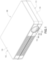
- the casing 100 is of a cuboid shape, a panel 110 is arranged on a side of the casing 100, and the panel 110 is of a rectangular shape.
- the casing 100 has a plurality of side plates adjacent to a periphery of the panel 110, the casing 100 may be placed in a manner of any one of a plurality of placing positions corresponding to one of the side plates 111, 112.
- the casing 100 according to this embodiment has two side plates 111, 112 as the bottom corresponding to two placing positions. Accordingly, the casing 100 may be placed in a manner of the first placing position, and the first side plate 111 is configured as the bottom. Moreover, the casing 100 may stand in a manner of the second placing position as shown in Fig. 6 , and the second side plate 112 is configured as the bottom.
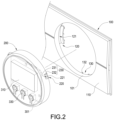
- a circular opening 101 is defined on the panel 110, and a first fixing structure 120 is arranged on an internal edge of the circular opening 101.
- the circular frame 200 may be a circular ring, a circular plate or a cylinder, an exterior profile of the circular frame 200 is matched with an interior profile of the circular opening 101, the circular frame 200 is rotatably arranged in the circular opening 101 to close the circular opening 101.
- the circular frame 200 may be protruded from the panel 110 to facilitate the usage for a user of rotating the circular frame 200, but this disclosure is not limited to this embodiment.
- the circular frame 200 may be disposed in a coplanar manner with the panel 110 or be recessed in the circular opening 101.
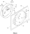
- a second fixing structure 220 is arranged at an external edge of the circular frame 200, the second fixing structure 220 is annularly arranged at a circular external edge of the circular frame 200 corresponding to the first fixing structure 120, and the second fixing structure 220 is slidable with the circular frame 200 and limited in the first fixing structure 120. Therefore, the circular frame 200 is limited at the circular opening 101 of the panel 110 of the casing 100. Furthermore, the second fixing structure 220 on the periphery of the circular frame 200 is slidable along a circumferential direction in the first fixing structure 120, and the circular frame 200 is rotatable relative to the circular opening 101. According to this embodiment, the second fixing structure 220 is annularly arranged on a circular profile defined by the circular external edge of the circular frame 200 corresponding to the first fixing structure 120, but this disclosure is not limited to this embodiment.
- the first fixing structure 120 has a curve slot 121
- the second fixing structure 220 has a sliding latch 221 arranged concentrically with the circular frame 200
- the sliding latch 221 is latched to the curve slot 121.
- the sliding latch 221 is slidable in the curve slot 121 to avoid the interference to a rotation of the circular frame 200.
- the display 310 is embedded in the circular frame 200 and exposed on the panel 110, the display 310 may be provided with an electric connector 320 for electrically connecting to a main board (not shown in figures) of an electronic device via a cable (not shown in figures) to display information related to status of the electronic device, and an operating interface 330 electrically connected with the main board is arranged on the circular frame 200 for an operation to the electronic device by the user.
- the display 310, the electric connector 320 and the operating interface 330 may be arranged on a sub circuit board 301.
- the type of the operating interface 330 is not limited in this disclosure.
- the operating interface 330 may be physical keys or a touch screen integrated with the interface display 310.
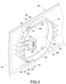
- a first positioning structure 130 is arranged on the internal edge of the circular opening 101
- a second positioning structure 230 is correspondingly arranged at the external edge of the circular frame 200.
- the circular frame 200 is rotatable relative to the circular opening 101 to one of the predetermined positions, and the circular frame 200 may be rotated from any one of the predetermined positions to another predetermined position through an angle in multiples of 90 degrees.
- the first positioning structure 130 and the second positioning structure 230 may block each other along a circumferential direction of the circular opening 101 to prevent the circular frame 200 from an unexpected displacement.
- the circular frame 200 is limited by the first positioning structure 130 and the second positioning structure 230 to be rotatable relative to the circular opening 101 between the first predetermined position shown in Fig. 1 to Fig. 4 and the second predetermined position shown in Fig. 5 to Fig. 6 .
- Fig. 1 when the casing 100 is placed at a flat status and the first side plate 111 is configured as the bottom, the circular frame 200 may be correspondingly rotated to the first predetermined position, so that an operator may squarely watch the display 310.
- Fig. 6 when the casing 100 is kept in an up-right status and the second side plate 112 is configured as the bottom, the circular frame 200 may be correspondingly rotated to the second predetermined position, so that the operator may squarely watch the display 310.
- the casing 100 is rotated through an angle in multiples of 90 degrees when being rotated to shift between the plurality of flat and up-right placing positions.
- the two side plates 111, 112 are arranged adjacently and perpendicularly to each other, and the circular frame 200 may be rotated between the two predetermined positions in an angle of 90 degrees correspondingly.
- the rotating angle is not limited in this disclosure.
- the casing 100 may have two side plates parallel with each other 111, 113(or 112, 114) used for the bottom, and the circular frame 200 may be rotated between the two predetermined positions in an angle of 180 degrees correspondingly.
- number of the predetermined positions is not limited in this disclosure either.
- the casing 100 may have three adjacent side plates 111, 112, 113 used for the bottom, the circular frame 200 may be rotated to three predetermined positions, and the rotating angles of 90 degrees are disposed between adjacent predetermined positions correspondingly.
- the first positioning structure 130 and the second positioning structure 230 may respectively have a block 132/232, when the circular frame 200 is located at a predetermined position which is at an end of a rotatable range, the pair of blocks 132/232 abut against each other and stop each other unidirectionally along the circumferential direction of the circular opening 101 so as to prevent the cable from a damage caused by over twisting when the circular frame 200 is rotated out of a predetermined range.
- the first positioning structure 130 may have a spherical tenon 131
- the second positioning structure 230 may have a positioning hole 231 for snapping the spherical tenon 131.
- the spherical tenon 131 snaps the positioning hole 231 along a direction parallel with a central axis of the circular opening 101, so that the circular frame 200 is positioned by the first positioning structure 130 and the second positioning structure 230 to be prevented from an unexpected rotation.
- the aforementioned spherical tenon 131 and the positioning hole 231 may be exchanged in position, namely the second positioning structure 230 may have a spherical tenon 131 and the first positioning structure 130 may have a positioning hole 231 for snapping the spherical tenon 131.
- Multiple spherical tenons 131 or multiple positioning holes 231 may be arranged according to an arrangement of the predetermined positions.
- a function of the spherical tenon 131 is that the spherical tenon 131 may slip out of the snapped positioning hole 231 to allow the rotation of the circular frame 200 when the user rotates the circular frame 200 with a sufficient torque.
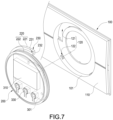
- an electronic device having a casing 100, a circular frame 200 and a display 310 is provided.
- the second embodiment is similar to the first embodiment shown in Fig. 1 .
- the casing 100 is of a cuboid shape, a panel 110 is arranged on a side of the casing 100, and the panel 110 is of a rectangular shape.
- a circular opening 101 is defined on the panel 110, and a first fixing structure 120 is arranged at an internal edge of the circular opening 101.
- the circular frame 200 may be a circular ring, a circular plate or a cylinder, an exterior profile of the circular frame 200 is matched with an interior profile of the circular opening 101, the circular frame 200 is rotatably arranged in the circular opening 101 to close the circular opening 101.
- the circular frame 200 may be protruded from the panel 110 to facilitate the usage for the user of rotating the circular frame 200, but this disclosure is not limited to this embodiment.
- the circular frame 200 may be disposed in a coplanar manner with the panel 110 or be recessed in the circular opening 101.
- a second fixing structure 220 is arranged at an external edge of the circular frame 200, the second fixing structure 220 snaps the first fixing structure 120 to fix the circular frame 200 on the casing 100.
- the first fixing structure 120 has a sliding latch 122
- the second fixing structure 220 correspondingly has a curve slot 222 arranged concentrically with the circular frame 200.
- the second fixing structure 220 further has a sliding latch 221, the sliding latch 221 is extended of a curved shape according to this embodiment.
- the first fixing structure 120 correspondingly has a curve slot 121 arranged concentrically with the circular opening 101.
- the sliding latches 122, 221 respectively snap each curve slot 222/121 to fix the circular frame 200 on the casing 100.
- each sliding latch 122/221 is slidable in each corresponding curve slot 222/121 to avoid the interference to a rotation of the circular frame 200.
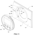
- the display 310 is embedded in the circular frame 200 and exposed on the panel 110, the display 310 may be provided with an electric connector 320 for electrically connecting to a main board (not shown in figures) of an electronic device via a cable (not shown in figures) to display information related to status of the electronic device, and an operating interface 330 electrically connected with the main board is arranged on the circular frame 200 for an operation to the electronic device by the user.
- the display 310, the electric connector 320 and the operating interface 330 may be arranged on a sub circuit board 301.
- the type of the operating interface 330 is not limited in this disclosure.
- the operating interface 330 may be physical keys or a touch screen integrated with the interface display 310.
- a first positioning structure 130 is arranged on the internal edge of the circular opening 101
- a second positioning structure 230 is correspondingly arranged at the external edge of the circular frame 200.
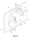
- the circular frame 200 may be correspondingly rotated to one of a plurality of predetermined positions relative to the circular opening 101, and the circular frame 200 may be rotated from one of the predetermined positions to another predetermined position through an angle in multiples of 90 degrees.
- one of the predetermined positions is shown in Fig. 7 to Fig. 9
- another predetermined position is shown in Fig. 10 .
- the first positioning structure 130 and the second positioning structure 230 may block each other along a circumferential direction of the circular opening 101 to prevent the circular frame 200 from an unexpected displacement.
- the first positioning structure 130 and the second positioning structure 230 may respectively have a block 132/232, when the circular frame 200 is located at a predetermined position which is at an end of a rotatable range, the pair of blocks 132/232 abut against each other and block each other unidirectionally along the circumferential direction of the circular opening 101 so as to prevent the cable from a damage caused by over twisting when the circular frame 200 is rotated out of a predetermined range.
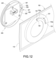
- the first positioning structure 130 may have a spherical tenon 131
- the second positioning structure 230 may have a positioning hole 231 for snapping the spherical tenon 131.
- the spherical tenon 131 snaps the positioning hole 231 along a direction parallel with a central axis of the circular opening 101, so that the circular frame 200 is positioned by the first positioning structure 130 and the second positioning structure 230 to be prevented from an unexpected rotation.
- the aforementioned spherical tenon 131 and the positioning hole 231 may be exchanged in position, namely the second positioning structure 230 may have a spherical tenon 131 and the first positioning structure 130 may have a positioning hole 231 for snapping the spherical tenon 131.
- Multiple spherical tenons 131 or multiple positioning holes 231 may be arranged according to an arrangement of the predetermined positions.
- a function of the spherical tenon 131 is that the spherical tenon 131 may slip out of the snapped positioning hole 231 to allow the rotation of the circular frame 200 when the user rotates the circular frame 200 with a sufficient torque.
- an electronic device having a casing 100, a circular frame 200 and a display 310 is provided.
- the third embodiment is similar to the first embodiment shown in Fig. 1 .
- the casing 100 is of a cuboid shape
- a panel 110 is arranged on a side of the casing 100
- the panel 110 is of a rectangular shape.
- a circular opening 101 is defined on the panel 110, and a first fixing structure 120 is arranged at an internal edge of the circular opening 101.
- the circular frame 200 may be a circular ring, a circular plate or a cylinder, an exterior profile of the circular frame 200 is matched with an interior profile of the circular opening 101, the circular frame 200 is rotatably arranged in the circular opening 101 to close the circular opening 101.
- the circular frame 200 may be protruded from the panel 110 to facilitate the usage for the user of rotating the circular frame 200, but this disclosure is not limited to this embodiment.
- the circular frame 200 may be disposed in a coplanar manner with the panel 110 or be recessed in the circular opening 101.
- a second fixing structure 220 is arranged at an external edge of the circular frame 200, the second fixing structure 220 snaps the first fixing structure 120 to fix the circular frame 200 on the casing 100.
- the second fixing structure 220 has a sliding latch 221
- the first fixing structure 120 has a curve slot 121 arranged concentrically with the circular opening 101
- the sliding latch 221 snaps the corresponding curve slot 121 so as to fix the circular frame 200 on the casing 100.
- the sliding latch 221 is slidable in each corresponding curve slot 121 to avoid the interference to a rotation of the circular frame 200.
- the display 310 is embedded in the circular frame 200 and exposed on the panel 110, the display 310 may be provided with an electric connector 320 for electrically connecting to a main board (not shown in figures) of an electronic device via a cable (not shown in figures) to display information related to status of the electronic device, and an operating interface 330 electrically connected with the main board is arranged on the circular frame 200 for an operation to the electronic device by the user.
- the display 310, the electric connector 320 and the operating interface 330 may be arranged on a sub circuit board 301.
- the type of the operating interface 330 is not limited in this disclosure.
- the operating interface 330 may be physical keys or a touch screen integrated with the interface display 310.
- a first positioning structure 130 is arranged on the internal edge of the circular opening 101
- a second positioning structure 230 is correspondingly arranged at the external edge of the circular frame 200
- the circular frame 200 may be correspondingly rotated to one of a plurality of predetermined positions relative to the circular opening 101
- the circular frame 200 may be rotated from any of the predetermined positions to another predetermined position through an angle in multiples of 90 degrees.
- the first positioning structure 130 and the second positioning structure 230 may block each other along a circumferential direction of the circular opening 101 to prevent the circular frame 200 from an unexpected displacement.
- two ends of a rotatable range of the circular frame 200 respectively have a predetermined position
- the first positioning structure 130 and the second positioning structure 230 may be buckled with each other along the circumferential direction of the circular opening 101 when the circular frame 200 is located at any one of the predetermined positions.
- the second fixing structure 220 and the second positioning structure 230 are disposed on the same rod extended from the circular frame 200 according to this embodiment
- the sliding latch 221 of the second fixing structure 220 is disposed on a tip of the rod
- the sliding latch 221 may be of a spherical shape to facilitate the buckling to the curve slot 121.
- the first positioning structure 130 has a latched notch 133
- the latched notch 133 has at least one neck opening 133a.
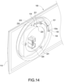
- two latched notches 133 are disposed corresponding to the two predetermined positions shown in Fig. 13 and Fig. 14
- the two latched notches 133 respectively communicate with two ends of the curve slot 121 through the neck openings 133a
- the second positioning structure 230 has a cylinder 233 inserted in the curve slot 121 for buckling the latched notch 133.
- the cylinder 233 is formed on a middle segment of the rod and is movable along the curve slot 121 with the rotation of the circular frame 200.
- the cylinder 233 may snap into the neck opening 133a of the latched notch 133 correspondingly so as to be fixed in the latched notch 133 to position the circular frame 200.
- the cylinder 233 has a curved surface so that the cylinder 233 may slip out of the snapped latched notch 133 to allow the rotation of the circular frame 200.
- a latched notch 133 may be additionally arranged at a middle segment of the curve slot 121, and an angle in multiples of 90 degrees is defined between the adjacent latched notches 133 relative to a center of the circular opening 101.
- the display 310 is rotatably arranged in the circular opening 101 on the casing 100 by the circular frame 200, so that the display 310 may be rotated according to various placing positions of the casing 100 to facilitate the usage for the user. According to the electronic device of this disclosure, the display 310 may be rotated without detaching the display 310, so that the user may be prevented from electric shock caused by touching exposed components. Further, the display 310 is not limited to be of a square shape.
Landscapes
- Engineering & Computer Science (AREA)
- Computer Hardware Design (AREA)
- Theoretical Computer Science (AREA)
- Microelectronics & Electronic Packaging (AREA)
- Human Computer Interaction (AREA)
- Physics & Mathematics (AREA)
- General Engineering & Computer Science (AREA)
- General Physics & Mathematics (AREA)
- Casings For Electric Apparatus (AREA)
- Devices For Indicating Variable Information By Combining Individual Elements (AREA)
- Pivots And Pivotal Connections (AREA)
Claims (11)
- Elektronische Vorrichtung, die Folgendes umfasst:ein Gehäuse (100), das eine Platte (110), die an einer Seite davon angeordnet ist, und eine Vielzahl von Seitenplatten (111, 112), die an einen Umfang der Platte (110) angrenzen, eine kreisförmige Öffnung (101), die in der Platte (110) definiert ist, und eine erste Befestigungsstruktur (120), die an einem Innenrand der kreisförmigen Öffnung (101) angeordnet ist, umfasst;einen kreisförmigen Rahmen (200), der drehbar in der kreisförmigen Öffnung (101) angeordnet ist und die kreisförmige Öffnung (101) verschließt, eine zweite Befestigungsstruktur (220), die an einem Außenrand des kreisförmigen Rahmens (200) angeordnet ist, wobei die zweite Befestigungsstruktur (220), die am Umfang des kreisförmigen Rahmens (200) angeordnet ist, mit dem kreisförmigen Rahmen (200) entlang einer Umfangsrichtung in der ersten Befestigungsstruktur (120) verschiebbar ist, und der kreisförmige Rahmen (200) so konfiguriert ist, dass er relativ zu der kreisförmigen Öffnung drehbar ist und die zweite Befestigungsstruktur (220) durch die erste Befestigungsstruktur (120) begrenzt ist; undein Display (300), das in den kreisförmigen Rahmen (200) eingebettet ist und auf der Platte (110) freiliegt,wobei das Gehäuse (100) so konfiguriert ist, dass es auf einer der mehreren Seitenplatten (111, 112) als ein Boden des Gehäuses (100) platziert werden kann, und der kreisförmige Rahmen (200) drehbar ist, um eine Richtung der Anzeige (310) gemäß der Platzierungsposition des Gehäuses einzustellen, um eine Information anzuzeigen, die genau beobachtet werden kann,wobei die erste Befestigungsstruktur (120) eine Schiebeklinke (122) und die zweite Befestigungsstruktur (220) entsprechend einen konzentrisch zum kreisförmigen Rahmen (200) angeordneten Kurvenschlitz (222) aufweist, die zweite Befestigungsstruktur (220) eine weitere Schiebeklinke (221) und die erste Befestigungsstruktur (120) entsprechend einen weiteren konzentrisch zur kreisförmigen Öffnung (101) angeordneten Kurvenschlitz (121) aufweist,wobei die andere Schiebeklinke (221) von einer gekrümmten verlängert wird, wobei die Schiebeklinken (122, 221) jeweils in die gekrümmten Schlitze (222, 121) einrasten, um den kreisförmigen Rahmen (200) an dem Gehäuse (100) zu befestigen; undwobei die verschiebbaren Riegel (122, 221) jeweils in den Kurvenschlitzen (222, 121) verschiebbar sind, wenn der kreisförmige Rahmen (200) in der kreisförmigen Öffnung (101) gedreht wird.
- Elektronische Vorrichtung nach Anspruch 1, wobei der kreisförmige Rahmen (200) aus der Platte (110) herausragt.
- Elektronische Vorrichtung nach Anspruch 1, wobei an dem kreisförmigen Rahmen (200) eine Bedienoberfläche (330) angebracht ist.
- Elektronische Vorrichtung nach Anspruch 1, wobei das Gehäuse (100) quaderförmig und die Platte (110) rechteckig ist.
- Elektronische Vorrichtung nach Anspruch 1, wobei eine erste Positionierungsstruktur (130) am Innenrand der kreisförmigen Öffnung (101) angeordnet ist, eine zweite Positionierungsstruktur (230) am Außenrand des kreisförmigen Rahmens (200) angeordnet ist, der kreisförmige Rahmen (200) in Bezug auf die kreisförmige Öffnung (101) in eine von mehreren vorbestimmten Positionen, die der Platzierungsposition entsprechen, drehbar ist, wobei die erste Positionierungsstruktur (130) und die zweite Positionierungsstruktur (230) einander entlang einer Umfangsrichtung der kreisförmigen Öffnung (101) blockieren, wenn sich der kreisförmige Rahmen (200) in irgendeiner der vorbestimmten Positionen befindet.
- Elektronische Vorrichtung nach Anspruch 5, wobei, wenn sich der kreisförmige Rahmen (200) in einer der vorbestimmten Positionen befindet, die erste Positionierungsstruktur (130) und die zweite Positionierungsstruktur (230) entlang der Umfangsrichtung der kreisförmigen Öffnung (101) miteinander verbogen werden.
- Elektronische Vorrichtung nach Anspruch 5, wobei, wenn sich der kreisförmige Rahmen (200) in einer der vorbestimmten Positionen befindet, die erste Positionierungsstruktur (130) und die zweite Positionierungsstruktur (230) entlang einer axialen Richtung der kreisförmigen Öffnung (101) miteinander verbogen sind.
- Elektronische Vorrichtung nach Anspruch 7, wobei die erste Positionierungsstruktur (130) einen kugelförmigen Zapfen (131) umfasst, und die zweite Positionierungsstruktur (230) ein Positionierungsloch (231) umfasst, das mit dem kugelförmigen Zapfen (131) verbogen ist.
- Elektronische Vorrichtung nach Anspruch 7, wobei die zweite Positionierungsstruktur (230) einen kugelförmigen Zapfen (131) umfasst, und die erste Positionierungsstruktur (230) ein Positionierungsloch (231) umfasst, das mit dem kugelförmigen Zapfen (131) verbogen ist.
- Elektronische Vorrichtung nach Anspruch 5, wobei der kreisförmige Rahmen (200) aus einer der vorbestimmten Positionen in eine andere vorbestimmte Position um einen Winkel in Vielfachen von 90 Grad drehbar ist.
- Elektronische Vorrichtung nach Anspruch 5, wobei die erste Positionierungsstruktur (130) und die zweite Positionierungsstruktur (230) jeweils einen Block (132/232) umfassen, wenn sich der kreisförmige Rahmen (200) in einer der vorbestimmten Positionen befindet, stoßen zwei Blöcke (132, 232) aneinander und blockieren sich gegenseitig unidirektional entlang der Umfangsrichtung der kreisförmigen Öffnung (101).
Applications Claiming Priority (1)
| Application Number | Priority Date | Filing Date | Title |
|---|---|---|---|
| CN202110943154.4A CN115705077A (zh) | 2021-08-17 | 2021-08-17 | 电子装置 |
Publications (3)
| Publication Number | Publication Date |
|---|---|
| EP4138526A1 EP4138526A1 (de) | 2023-02-22 |
| EP4138526B1 true EP4138526B1 (de) | 2025-06-11 |
| EP4138526C0 EP4138526C0 (de) | 2025-06-11 |
Family
ID=79288012
Family Applications (1)
| Application Number | Title | Priority Date | Filing Date |
|---|---|---|---|
| EP22150351.9A Active EP4138526B1 (de) | 2021-08-17 | 2022-01-05 | Elektronische vorrichtung mit drehbarer anzeige |
Country Status (4)
| Country | Link |
|---|---|
| US (1) | US11991840B2 (de) |
| EP (1) | EP4138526B1 (de) |
| JP (2) | JP7337969B2 (de) |
| CN (1) | CN115705077A (de) |
Families Citing this family (1)
| Publication number | Priority date | Publication date | Assignee | Title |
|---|---|---|---|---|
| JP1706449S (ja) * | 2021-03-23 | 2022-02-01 | ライブストリーミング装置 |
Citations (1)
| Publication number | Priority date | Publication date | Assignee | Title |
|---|---|---|---|---|
| JP2016187297A (ja) * | 2013-05-21 | 2016-10-27 | 東芝三菱電機産業システム株式会社 | 無停電電源装置、無停電電源装置の状態表示装置 |
Family Cites Families (22)
| Publication number | Priority date | Publication date | Assignee | Title |
|---|---|---|---|---|
| TW342511B (en) * | 1996-05-10 | 1998-10-11 | Matsushita Electric Works Ltd | Time switch |
| JP2002074921A (ja) | 2000-08-29 | 2002-03-15 | Sharp Corp | 据え置き型電子機器 |
| TW519330U (en) * | 2001-09-04 | 2003-01-21 | Delta Electronics Inc | Rotating plug |
| JP2003262913A (ja) | 2002-03-11 | 2003-09-19 | Matsushita Electric Ind Co Ltd | カメラ付き携帯端末装置 |
| TWI255978B (en) * | 2003-03-28 | 2006-06-01 | Quanta Comp Inc | Electronic device and its combination structure with rotation buckle and signal transmission |
| JP2004318302A (ja) * | 2003-04-14 | 2004-11-11 | Sony Corp | 電子機器 |
| US7457120B2 (en) * | 2004-04-29 | 2008-11-25 | Samsung Sdi Co., Ltd. | Plasma display apparatus |
| US7377603B2 (en) | 2004-10-14 | 2008-05-27 | Hewlett-Packard Development Company, L.P. | Computing device mounting systems |
| JP2008192344A (ja) | 2007-02-01 | 2008-08-21 | Funai Electric Co Ltd | 表示ユニット及びこの表示ユニットを備えた光ディスク装置 |
| JP5043803B2 (ja) | 2008-11-04 | 2012-10-10 | 三菱電機株式会社 | 通電情報表示装置 |
| US8717755B2 (en) * | 2009-09-29 | 2014-05-06 | Hewlett-Packard Development Company, L.P. | Docking device mounting systems and methods |
| US8496488B2 (en) * | 2011-03-24 | 2013-07-30 | Cisco Technology, Inc. | Power input terminal block housing and cover |
| TWI540606B (zh) * | 2013-12-31 | 2016-07-01 | jin-xiong Chu | Knob code switch |
| US20150351267A1 (en) * | 2014-06-02 | 2015-12-03 | Emerson Network Power, Energy Systems, North America, Inc. | Latching assemblies for enclosures |
| CN105578815B (zh) * | 2016-01-05 | 2018-08-28 | 英业达科技有限公司 | 电子装置的掀盖式结构 |
| EP3291248A1 (de) * | 2016-09-02 | 2018-03-07 | MAD Technics GmbH | Steuerbarer drehknopf |
| CN206755256U (zh) * | 2017-04-12 | 2017-12-15 | 上海纯米电子科技有限公司 | 具有防水结构的电磁炉 |
| US11567111B2 (en) * | 2018-11-10 | 2023-01-31 | Setra Systems, Inc. | Measurement device and method of its operation |
| CN209215975U (zh) * | 2019-02-02 | 2019-08-06 | 迪尔阿扣基金两合公司 | 包括旋钮装置的电器设备 |
| US11981477B2 (en) * | 2019-10-23 | 2024-05-14 | Charles R. Driscoll | Storage container with attachable timer disc |
| US12016136B2 (en) * | 2020-06-01 | 2024-06-18 | The Toro Company | Irrigation controller having a rotatable and non-detachable user interface module |
| CN213576957U (zh) * | 2020-09-15 | 2021-06-29 | 深圳磊迈照明科技有限公司 | 一种线形灯具的卯榫结构 |
-
2021
- 2021-08-17 CN CN202110943154.4A patent/CN115705077A/zh active Pending
-
2022
- 2022-01-03 US US17/567,601 patent/US11991840B2/en active Active
- 2022-01-05 EP EP22150351.9A patent/EP4138526B1/de active Active
- 2022-01-05 JP JP2022000681A patent/JP7337969B2/ja active Active
-
2023
- 2023-08-23 JP JP2023135484A patent/JP7526329B2/ja active Active
Patent Citations (1)
| Publication number | Priority date | Publication date | Assignee | Title |
|---|---|---|---|---|
| JP2016187297A (ja) * | 2013-05-21 | 2016-10-27 | 東芝三菱電機産業システム株式会社 | 無停電電源装置、無停電電源装置の状態表示装置 |
Also Published As
| Publication number | Publication date |
|---|---|
| JP2023157983A (ja) | 2023-10-26 |
| JP2023027737A (ja) | 2023-03-02 |
| EP4138526A1 (de) | 2023-02-22 |
| JP7337969B2 (ja) | 2023-09-04 |
| CN115705077A (zh) | 2023-02-17 |
| EP4138526C0 (de) | 2025-06-11 |
| US11991840B2 (en) | 2024-05-21 |
| US20230058284A1 (en) | 2023-02-23 |
| JP7526329B2 (ja) | 2024-07-31 |
Similar Documents
| Publication | Publication Date | Title |
|---|---|---|
| EP2669759B1 (de) | Scharniervorrichtung und Rechenvorrichtung damit | |
| US6821134B2 (en) | Rotatable plug applied in power supply apparatus | |
| US8430679B1 (en) | Rotatable power strip | |
| EP3065153A1 (de) | Schaltvorrichtung mit klemmenabdeckung und verfahren | |
| JP2020504874A (ja) | フレキシブル電子装置 | |
| EP4138526B1 (de) | Elektronische vorrichtung mit drehbarer anzeige | |
| JP2020506458A (ja) | フレキシブル電子装置 | |
| JP2020504869A (ja) | フレキシブル電子装置 | |
| US8050025B2 (en) | Cover mechanism and electronic device using same | |
| WO2020077618A1 (en) | Battery packs containing configurable terminal holder | |
| US8345416B2 (en) | Portable electronic device with interface protector | |
| JP4391306B2 (ja) | 多方向押圧型スイッチ | |
| CN101738520A (zh) | 通电信息显示装置 | |
| US20160062416A1 (en) | Hinge apparatus and electronic device | |
| CN113223887B (zh) | 按钮开关 | |
| CN109994877A (zh) | 多功能数据线 | |
| JP5395687B2 (ja) | 回転コネクタ | |
| CN213304461U (zh) | 防护盒和电气组件 | |
| CN220693340U (zh) | 助听器 | |
| CN112511673B (zh) | 电子设备 | |
| CN215413769U (zh) | 仪表及其显示模块旋转组件 | |
| CN215379476U (zh) | 输入面板组件及充电面板组件 | |
| EP4589619A1 (de) | Schlüsselschalteranordnung und verfahren zu derer verwendung | |
| EP4509844A1 (de) | Drehmechanismus für eine messvorrichtung | |
| JP2003315363A (ja) | 表示装置 |
Legal Events
| Date | Code | Title | Description |
|---|---|---|---|
| PUAI | Public reference made under article 153(3) epc to a published international application that has entered the european phase |
Free format text: ORIGINAL CODE: 0009012 |
|
| STAA | Information on the status of an ep patent application or granted ep patent |
Free format text: STATUS: REQUEST FOR EXAMINATION WAS MADE |
|
| 17P | Request for examination filed |
Effective date: 20220913 |
|
| AK | Designated contracting states |
Kind code of ref document: A1 Designated state(s): AL AT BE BG CH CY CZ DE DK EE ES FI FR GB GR HR HU IE IS IT LI LT LU LV MC MK MT NL NO PL PT RO RS SE SI SK SM TR |
|
| STAA | Information on the status of an ep patent application or granted ep patent |
Free format text: STATUS: EXAMINATION IS IN PROGRESS |
|
| 17Q | First examination report despatched |
Effective date: 20241007 |
|
| GRAP | Despatch of communication of intention to grant a patent |
Free format text: ORIGINAL CODE: EPIDOSNIGR1 |
|
| STAA | Information on the status of an ep patent application or granted ep patent |
Free format text: STATUS: GRANT OF PATENT IS INTENDED |
|
| INTG | Intention to grant announced |
Effective date: 20250122 |
|
| GRAS | Grant fee paid |
Free format text: ORIGINAL CODE: EPIDOSNIGR3 |
|
| GRAA | (expected) grant |
Free format text: ORIGINAL CODE: 0009210 |
|
| STAA | Information on the status of an ep patent application or granted ep patent |
Free format text: STATUS: THE PATENT HAS BEEN GRANTED |
|
| AK | Designated contracting states |
Kind code of ref document: B1 Designated state(s): AL AT BE BG CH CY CZ DE DK EE ES FI FR GB GR HR HU IE IS IT LI LT LU LV MC MK MT NL NO PL PT RO RS SE SI SK SM TR |
|
| REG | Reference to a national code |
Ref country code: GB Ref legal event code: FG4D |
|
| REG | Reference to a national code |
Ref country code: CH Ref legal event code: EP |
|
| REG | Reference to a national code |
Ref country code: DE Ref legal event code: R096 Ref document number: 602022015683 Country of ref document: DE |
|
| REG | Reference to a national code |
Ref country code: IE Ref legal event code: FG4D |
|
| U01 | Request for unitary effect filed |
Effective date: 20250625 |
|
| U07 | Unitary effect registered |
Designated state(s): AT BE BG DE DK EE FI FR IT LT LU LV MT NL PT RO SE SI Effective date: 20250702 |
|
| PG25 | Lapsed in a contracting state [announced via postgrant information from national office to epo] |
Ref country code: ES Free format text: LAPSE BECAUSE OF FAILURE TO SUBMIT A TRANSLATION OF THE DESCRIPTION OR TO PAY THE FEE WITHIN THE PRESCRIBED TIME-LIMIT Effective date: 20250611 |
|
| PG25 | Lapsed in a contracting state [announced via postgrant information from national office to epo] |
Ref country code: GR Free format text: LAPSE BECAUSE OF FAILURE TO SUBMIT A TRANSLATION OF THE DESCRIPTION OR TO PAY THE FEE WITHIN THE PRESCRIBED TIME-LIMIT Effective date: 20250912 Ref country code: NO Free format text: LAPSE BECAUSE OF FAILURE TO SUBMIT A TRANSLATION OF THE DESCRIPTION OR TO PAY THE FEE WITHIN THE PRESCRIBED TIME-LIMIT Effective date: 20250911 |
|
| PG25 | Lapsed in a contracting state [announced via postgrant information from national office to epo] |
Ref country code: HR Free format text: LAPSE BECAUSE OF FAILURE TO SUBMIT A TRANSLATION OF THE DESCRIPTION OR TO PAY THE FEE WITHIN THE PRESCRIBED TIME-LIMIT Effective date: 20250611 |
|
| PG25 | Lapsed in a contracting state [announced via postgrant information from national office to epo] |
Ref country code: RS Free format text: LAPSE BECAUSE OF FAILURE TO SUBMIT A TRANSLATION OF THE DESCRIPTION OR TO PAY THE FEE WITHIN THE PRESCRIBED TIME-LIMIT Effective date: 20250911 |
|
| PG25 | Lapsed in a contracting state [announced via postgrant information from national office to epo] |
Ref country code: IS Free format text: LAPSE BECAUSE OF FAILURE TO SUBMIT A TRANSLATION OF THE DESCRIPTION OR TO PAY THE FEE WITHIN THE PRESCRIBED TIME-LIMIT Effective date: 20251011 |
|
| PGFP | Annual fee paid to national office [announced via postgrant information from national office to epo] |
Ref country code: GB Payment date: 20251113 Year of fee payment: 5 |
|
| PG25 | Lapsed in a contracting state [announced via postgrant information from national office to epo] |
Ref country code: SM Free format text: LAPSE BECAUSE OF FAILURE TO SUBMIT A TRANSLATION OF THE DESCRIPTION OR TO PAY THE FEE WITHIN THE PRESCRIBED TIME-LIMIT Effective date: 20250611 |
|
| U20 | Renewal fee for the european patent with unitary effect paid |
Year of fee payment: 5 Effective date: 20251205 |
|
| PG25 | Lapsed in a contracting state [announced via postgrant information from national office to epo] |
Ref country code: CZ Free format text: LAPSE BECAUSE OF FAILURE TO SUBMIT A TRANSLATION OF THE DESCRIPTION OR TO PAY THE FEE WITHIN THE PRESCRIBED TIME-LIMIT Effective date: 20250611 |
|
| PG25 | Lapsed in a contracting state [announced via postgrant information from national office to epo] |
Ref country code: PL Free format text: LAPSE BECAUSE OF FAILURE TO SUBMIT A TRANSLATION OF THE DESCRIPTION OR TO PAY THE FEE WITHIN THE PRESCRIBED TIME-LIMIT Effective date: 20250611 |
|
| PG25 | Lapsed in a contracting state [announced via postgrant information from national office to epo] |
Ref country code: SK Free format text: LAPSE BECAUSE OF FAILURE TO SUBMIT A TRANSLATION OF THE DESCRIPTION OR TO PAY THE FEE WITHIN THE PRESCRIBED TIME-LIMIT Effective date: 20250611 |