EP4138162A1 - Electrochemical cell device - Google Patents
Electrochemical cell device Download PDFInfo
- Publication number
- EP4138162A1 EP4138162A1 EP21787933.7A EP21787933A EP4138162A1 EP 4138162 A1 EP4138162 A1 EP 4138162A1 EP 21787933 A EP21787933 A EP 21787933A EP 4138162 A1 EP4138162 A1 EP 4138162A1
- Authority
- EP
- European Patent Office
- Prior art keywords
- porous body
- metal porous
- body sheet
- main surface
- current collector
- Prior art date
- Legal status (The legal status is an assumption and is not a legal conclusion. Google has not performed a legal analysis and makes no representation as to the accuracy of the status listed.)
- Pending
Links
- 229910052751 metal Inorganic materials 0.000 claims abstract description 254
- 239000002184 metal Substances 0.000 claims abstract description 254
- PXHVJJICTQNCMI-UHFFFAOYSA-N Nickel Chemical compound [Ni] PXHVJJICTQNCMI-UHFFFAOYSA-N 0.000 claims description 20
- 239000011248 coating agent Substances 0.000 claims description 10
- 238000000576 coating method Methods 0.000 claims description 10
- 229910052759 nickel Inorganic materials 0.000 claims description 9
- 239000007787 solid Substances 0.000 claims description 8
- 239000000446 fuel Substances 0.000 claims description 7
- 229910017052 cobalt Inorganic materials 0.000 claims description 5
- 239000010941 cobalt Substances 0.000 claims description 5
- GUTLYIVDDKVIGB-UHFFFAOYSA-N cobalt atom Chemical compound [Co] GUTLYIVDDKVIGB-UHFFFAOYSA-N 0.000 claims description 5
- 238000005868 electrolysis reaction Methods 0.000 claims description 4
- 230000002093 peripheral effect Effects 0.000 claims description 2
- 239000007784 solid electrolyte Substances 0.000 description 11
- 230000003247 decreasing effect Effects 0.000 description 6
- 230000000694 effects Effects 0.000 description 5
- 238000010248 power generation Methods 0.000 description 3
- 238000003487 electrochemical reaction Methods 0.000 description 2
- 229910052684 Cerium Inorganic materials 0.000 description 1
- 229910052688 Gadolinium Inorganic materials 0.000 description 1
- GWXLDORMOJMVQZ-UHFFFAOYSA-N cerium Chemical compound [Ce] GWXLDORMOJMVQZ-UHFFFAOYSA-N 0.000 description 1
- 239000004020 conductor Substances 0.000 description 1
- 230000000994 depressogenic effect Effects 0.000 description 1
- UIWYJDYFSGRHKR-UHFFFAOYSA-N gadolinium atom Chemical compound [Gd] UIWYJDYFSGRHKR-UHFFFAOYSA-N 0.000 description 1
- 229910052746 lanthanum Inorganic materials 0.000 description 1
- FZLIPJUXYLNCLC-UHFFFAOYSA-N lanthanum atom Chemical compound [La] FZLIPJUXYLNCLC-UHFFFAOYSA-N 0.000 description 1
- 238000000034 method Methods 0.000 description 1
- 239000000203 mixture Substances 0.000 description 1
- 238000012986 modification Methods 0.000 description 1
- 230000004048 modification Effects 0.000 description 1
- VSZWPYCFIRKVQL-UHFFFAOYSA-N selanylidenegallium;selenium Chemical compound [Se].[Se]=[Ga].[Se]=[Ga] VSZWPYCFIRKVQL-UHFFFAOYSA-N 0.000 description 1
- 229910052712 strontium Inorganic materials 0.000 description 1
- CIOAGBVUUVVLOB-UHFFFAOYSA-N strontium atom Chemical compound [Sr] CIOAGBVUUVVLOB-UHFFFAOYSA-N 0.000 description 1
- 229910052727 yttrium Inorganic materials 0.000 description 1
- VWQVUPCCIRVNHF-UHFFFAOYSA-N yttrium atom Chemical compound [Y] VWQVUPCCIRVNHF-UHFFFAOYSA-N 0.000 description 1
Images


Classifications
-
- H—ELECTRICITY
- H01—ELECTRIC ELEMENTS
- H01M—PROCESSES OR MEANS, e.g. BATTERIES, FOR THE DIRECT CONVERSION OF CHEMICAL ENERGY INTO ELECTRICAL ENERGY
- H01M8/00—Fuel cells; Manufacture thereof
- H01M8/02—Details
- H01M8/0202—Collectors; Separators, e.g. bipolar separators; Interconnectors
- H01M8/0247—Collectors; Separators, e.g. bipolar separators; Interconnectors characterised by the form
-
- H—ELECTRICITY
- H01—ELECTRIC ELEMENTS
- H01M—PROCESSES OR MEANS, e.g. BATTERIES, FOR THE DIRECT CONVERSION OF CHEMICAL ENERGY INTO ELECTRICAL ENERGY
- H01M4/00—Electrodes
- H01M4/86—Inert electrodes with catalytic activity, e.g. for fuel cells
- H01M4/8605—Porous electrodes
- H01M4/8621—Porous electrodes containing only metallic or ceramic material, e.g. made by sintering or sputtering
-
- C—CHEMISTRY; METALLURGY
- C25—ELECTROLYTIC OR ELECTROPHORETIC PROCESSES; APPARATUS THEREFOR
- C25B—ELECTROLYTIC OR ELECTROPHORETIC PROCESSES FOR THE PRODUCTION OF COMPOUNDS OR NON-METALS; APPARATUS THEREFOR
- C25B1/00—Electrolytic production of inorganic compounds or non-metals
- C25B1/01—Products
- C25B1/02—Hydrogen or oxygen
- C25B1/04—Hydrogen or oxygen by electrolysis of water
- C25B1/042—Hydrogen or oxygen by electrolysis of water by electrolysis of steam
-
- C—CHEMISTRY; METALLURGY
- C25—ELECTROLYTIC OR ELECTROPHORETIC PROCESSES; APPARATUS THEREFOR
- C25B—ELECTROLYTIC OR ELECTROPHORETIC PROCESSES FOR THE PRODUCTION OF COMPOUNDS OR NON-METALS; APPARATUS THEREFOR
- C25B9/00—Cells or assemblies of cells; Constructional parts of cells; Assemblies of constructional parts, e.g. electrode-diaphragm assemblies; Process-related cell features
- C25B9/01—Electrolytic cells characterised by shape or form
-
- C—CHEMISTRY; METALLURGY
- C25—ELECTROLYTIC OR ELECTROPHORETIC PROCESSES; APPARATUS THEREFOR
- C25B—ELECTROLYTIC OR ELECTROPHORETIC PROCESSES FOR THE PRODUCTION OF COMPOUNDS OR NON-METALS; APPARATUS THEREFOR
- C25B9/00—Cells or assemblies of cells; Constructional parts of cells; Assemblies of constructional parts, e.g. electrode-diaphragm assemblies; Process-related cell features
- C25B9/60—Constructional parts of cells
- C25B9/65—Means for supplying current; Electrode connections; Electric inter-cell connections
-
- C—CHEMISTRY; METALLURGY
- C25—ELECTROLYTIC OR ELECTROPHORETIC PROCESSES; APPARATUS THEREFOR
- C25B—ELECTROLYTIC OR ELECTROPHORETIC PROCESSES FOR THE PRODUCTION OF COMPOUNDS OR NON-METALS; APPARATUS THEREFOR
- C25B9/00—Cells or assemblies of cells; Constructional parts of cells; Assemblies of constructional parts, e.g. electrode-diaphragm assemblies; Process-related cell features
- C25B9/70—Assemblies comprising two or more cells
- C25B9/73—Assemblies comprising two or more cells of the filter-press type
- C25B9/77—Assemblies comprising two or more cells of the filter-press type having diaphragms
-
- H—ELECTRICITY
- H01—ELECTRIC ELEMENTS
- H01M—PROCESSES OR MEANS, e.g. BATTERIES, FOR THE DIRECT CONVERSION OF CHEMICAL ENERGY INTO ELECTRICAL ENERGY
- H01M8/00—Fuel cells; Manufacture thereof
- H01M8/02—Details
- H01M8/0202—Collectors; Separators, e.g. bipolar separators; Interconnectors
- H01M8/023—Porous and characterised by the material
- H01M8/0232—Metals or alloys
-
- H—ELECTRICITY
- H01—ELECTRIC ELEMENTS
- H01M—PROCESSES OR MEANS, e.g. BATTERIES, FOR THE DIRECT CONVERSION OF CHEMICAL ENERGY INTO ELECTRICAL ENERGY
- H01M8/00—Fuel cells; Manufacture thereof
- H01M8/02—Details
- H01M8/0202—Collectors; Separators, e.g. bipolar separators; Interconnectors
- H01M8/023—Porous and characterised by the material
- H01M8/0241—Composites
- H01M8/0245—Composites in the form of layered or coated products
-
- H—ELECTRICITY
- H01—ELECTRIC ELEMENTS
- H01M—PROCESSES OR MEANS, e.g. BATTERIES, FOR THE DIRECT CONVERSION OF CHEMICAL ENERGY INTO ELECTRICAL ENERGY
- H01M8/00—Fuel cells; Manufacture thereof
- H01M8/10—Fuel cells with solid electrolytes
- H01M8/12—Fuel cells with solid electrolytes operating at high temperature, e.g. with stabilised ZrO2 electrolyte
- H01M2008/1293—Fuel cells with solid oxide electrolytes
-
- Y—GENERAL TAGGING OF NEW TECHNOLOGICAL DEVELOPMENTS; GENERAL TAGGING OF CROSS-SECTIONAL TECHNOLOGIES SPANNING OVER SEVERAL SECTIONS OF THE IPC; TECHNICAL SUBJECTS COVERED BY FORMER USPC CROSS-REFERENCE ART COLLECTIONS [XRACs] AND DIGESTS
- Y02—TECHNOLOGIES OR APPLICATIONS FOR MITIGATION OR ADAPTATION AGAINST CLIMATE CHANGE
- Y02E—REDUCTION OF GREENHOUSE GAS [GHG] EMISSIONS, RELATED TO ENERGY GENERATION, TRANSMISSION OR DISTRIBUTION
- Y02E60/00—Enabling technologies; Technologies with a potential or indirect contribution to GHG emissions mitigation
- Y02E60/10—Energy storage using batteries
-
- Y—GENERAL TAGGING OF NEW TECHNOLOGICAL DEVELOPMENTS; GENERAL TAGGING OF CROSS-SECTIONAL TECHNOLOGIES SPANNING OVER SEVERAL SECTIONS OF THE IPC; TECHNICAL SUBJECTS COVERED BY FORMER USPC CROSS-REFERENCE ART COLLECTIONS [XRACs] AND DIGESTS
- Y02—TECHNOLOGIES OR APPLICATIONS FOR MITIGATION OR ADAPTATION AGAINST CLIMATE CHANGE
- Y02E—REDUCTION OF GREENHOUSE GAS [GHG] EMISSIONS, RELATED TO ENERGY GENERATION, TRANSMISSION OR DISTRIBUTION
- Y02E60/00—Enabling technologies; Technologies with a potential or indirect contribution to GHG emissions mitigation
- Y02E60/30—Hydrogen technology
- Y02E60/50—Fuel cells
Definitions
- the present disclosure relates to an electrochemical cell device.
- the present application claims a priority based on Japanese Patent Application No. 2020-072919 filed on April 15, 2020 , the entire content of which is incorporated herein by reference.
- PTL 1 ( WO 2019/244480 ) describes a fuel cell.
- the fuel cell described in PTL 1 includes a solid electrolyte layer, an anode, a cathode, an anode side current collector, and a cathode side current collector.
- the anode and the cathode sandwich the solid electrolyte layer (hereinafter, the solid electrolyte layer sandwiched between the anode and the cathode will be referred to as "cell").
- the anode side current collector and the cathode side current collector sandwich the cell.
- Each of the anode side current collector and the cathode side current collector is constituted of a metal porous body sheet composed of a metal porous body having a framework with a three-dimensional network structure.
- An electrochemical cell device includes: a cell having a first main surface and a second main surface opposite to the first main surface; a first current collector having a third main surface facing the first main surface; and a second current collector having a fourth main surface facing the second main surface.
- the cell is warped to protrude from the second main surface toward the first main surface.
- the third main surface is provided with a recess at a position facing a central portion of the first main surface.
- the fourth main surface includes a protrusion at a position facing a central portion of the second main surface.
- Each of the first current collector and the second current collector is constituted of one or more metal porous body sheets each composed of a metal porous body having a framework with a three-dimensional network structure.
- the central portion of the first main surface includes a portion of the first main surface with a longest distance from a flat reference surface when the cell is placed on the reference surface such that the second main surface faces the reference surface.
- the central portion of the second main surface includes a portion of the second main surface with a longest distance from the reference surface when the cell is disposed on the reference surface such that the second main surface faces the reference surface.
- a cell may be warped.
- spaces are formed between the cell and the anode side current collector and between the cell and the cathode side current collector (contact between the cell and each current collector is deteriorated).
- the present disclosure provides an electrochemical cell device to reduce a space between a cell and a current collector.
- the space between the cell and the current collector can be reduced.
- Electrochemical cell device 100 is a solid oxide fuel cell (SOFC). Although electrochemical cell device 100 may be a solid oxide electrolysis cell (SOEC), the SOFC will be described below as an exemplary electrochemical cell device 100.
- SOFC solid oxide fuel cell
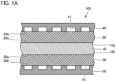
- Fig. 1A is a cross sectional view of electrochemical cell device 100.
- Fig. 1A shows a structure of a single-cell included in electrochemical cell device 100.
- Electrochemical cell device 100 is formed by stacking a plurality of single-cell structures. Further, Fig. 1A does not illustrate warpage of a cell 10, a recess 20c, and a protrusion 30c, which will be described later.
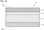
- Fig. 1B is an enlarged cross sectional view of cell 10. As shown in Figs. 1A and 1B , electrochemical cell device 100 includes cell 10, a current collector 20, a current collector 30, an interconnector 40, and an interconnector 50.
- Cell 10 has a main surface 10a and a main surface 10b.
- Main surface 10b is a surface opposite to main surface 10a.
- Cell 10 includes a solid electrolyte layer 11, a cathode 12, an anode 13, and an intermediate layer 14.
- Solid electrolyte layer 11 is a layer composed of a solid electrolyte.
- solid electrolyte layer 11 is composed of an oxide (YSZ) of zirconium (Zr) doped with yttrium (Y).
- Cathode 12 is composed of, for example, LSC (oxide of lanthanum (La) strontium (Sr) cobalt (Co)).
- Anode 13 is composed of, for example, a mixture of YSZ and an oxide of nickel (Ni 2 O).
- Intermediate layer 14 is composed of, for example, an oxide (GDC) of cerium (Ce) doped with gadolinium (Gd).
- Cathode 12 constitutes a main surface 10a of cell 10.
- Anode 13 constitutes a main surface 10b of cell 10.
- Solid electrolyte layer 11 is disposed between cathode 12 and anode 13.
- Intermediate layer 14 is disposed between solid electrolyte layer 11 and cathode 12. Solid electrolyte layer 11 and anode 13 are in contact with each other.
- Fig. 2 is a plan view of cell 10. As shown in Fig. 2 , cell 10 has a circular shape when viewed in a plan view. However, the planar shape of cell 10 is not limited thereto. Cell 10 may have a quadrangular shape when viewed in a plan view.
- Fig. 3 is a schematic cross sectional view showing a shape of warpage of cell 10.
- cell 10 is warped.
- cell 10 is warped to protrude from the main surface 10b side toward the main surface 10a side.
- a warpage amount of cell 10 (hereinafter, referred to as "warpage amount WA") is, for example, 100 ⁇ m or more.
- Warpage amount WA may be 1000 ⁇ m or more.
- Warpage amount WA is measured by the following method.
- Apex P is located at the central portion of cell 10 (the central portion of main surface 10a) when viewed in a plan view.
- Third, the thickness of cell 10 (hereinafter, referred to as "thickness T”) is subtracted from distance L. In this way, warpage amount WA is measured.
- the maximum width of cell 10 when viewed in a plan view is defined as a width W max (see Fig. 2 ).
- a value obtained by dividing warpage amount WA by width W max is, for example, 1/1000 or more.
- the value obtained by dividing warpage amount WA by width W max may be 1/100 or more.
- width W max is equal to the diameter of the circular shape.
- width W max is equal to the length of the diagonal of the quadrangular shape.
- current collector 20 is disposed on main surface 10a, and current collector 30 is disposed on main surface 10b. From another viewpoint, it can be said that cell 10 is sandwiched between current collector 20 and current collector 30.
- Current collector 20 is a cathode side current collector, and current collector 30 is an anode side current collector.
- Current collector 20 has a main surface 20a and a main surface 20b.
- Main surface 20a faces main surface 10a.
- Main surface 20b is a surface opposite to main surface 20a.
- Fig. 4 is a plan view of current collector 20.
- Fig. 5 is a cross sectional view at V-V of Fig. 4 .
- main surface 20a is provided with recess 20c.
- Main surface 20a is depressed toward the main surface 20b side in recess 20c.
- Recess 20c is disposed at a position facing the central portion of main surface 10a.
- Current collector 20 is constituted of a metal porous body sheet 21 and a metal porous body sheet 22.
- Each of metal porous body sheet 21 and metal porous body sheet 22 is composed of a metal porous body having a framework with a three-dimensional network structure.
- the framework of the metal porous body of each of metal porous body sheet 21 and metal porous body sheet 22 contains, for example, nickel (Ni) and cobalt.
- the coating weight of each of metal porous body sheet 21 and metal porous body sheet 22 is preferably 900 g/m 2 or less.
- the coating weight of metal porous body sheet 21 (metal porous body sheet 22) is a value obtained by dividing the weight of metal porous body sheet 21 (metal porous body sheet 22) by the area of the main surface of metal porous body sheet 21 (metal porous body sheet 22).
- Current collector 20 has a circular shape when viewed in a plan view.
- Metal porous body sheet 21 has a circular shape when viewed in a plan view.
- Metal porous body sheet 22 has an annular shape when viewed in a plan view. That is, a through hole 22a is formed in metal porous body sheet 22 so as to extend through metal porous body sheet 22 in the thickness direction of metal porous body sheet 22. Through hole 22a is formed at a position corresponding to recess 20c.
- the thickness (hereinafter, referred to as "thickness T2") of metal porous body sheet 22 is larger than the thickness (hereinafter, referred to as “thickness T1 ”) of metal porous body sheet 21.
- Metal porous body sheet 21 and metal porous body sheet 22 are disposed side by side (disposed not to be stacked on each other) in a plane orthogonal to the thickness direction of current collector 20.
- Metal porous body sheet 21 is disposed in through hole 22a. Therefore, metal porous body sheet 21 and through hole 22a constitute recess 20c.
- Current collector 30 has a main surface 30a and a main surface 30b.
- Main surface 30a faces main surface 10b.
- Main surface 30b is a surface opposite to main surface 30a.
- Fig. 6 is a plan view of current collector 30.
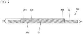
- Fig. 7 is a cross sectional view at VII-VII of Fig. 6 .
- main surface 30a has a protrusion 30c.
- protrusion 30c main surface 30a protrudes opposite to main surface 30b.
- Protrusion 30c is disposed at a position facing the central portion of main surface 10b.
- Current collector 30 is constituted of a metal porous body sheet 31 and a metal porous body sheet 32.
- Each of metal porous body sheet 31 and metal porous body sheet 32 is constituted of a metal porous body having a framework with a three-dimensional network structure.
- the framework of the metal porous body of each of metal porous body sheet 31 and metal porous body sheet 32 contains, for example, nickel.
- the coating weight of each of metal porous body sheet 31 and metal porous body sheet 32 is preferably 1000 g/m 2 or less.
- the coating weight of metal porous body sheet 31 (metal porous body sheet 32) is a value obtained by dividing the weight of metal porous body sheet 31 (metal porous body sheet 32) by the area of the main surface of metal porous body sheet 31 (metal porous body sheet 32).
- Current collector 30 has a circular shape when viewed in a plan view.
- Metal porous body sheet 31 has a circular shape when viewed in a plan view.
- Metal porous body sheet 32 has an annular shape when viewed in a plan view. That is, a through hole 32a is formed in metal porous body sheet 32 so as to extend through metal porous body sheet 32 in the thickness direction of metal porous body sheet 32. Through hole 32a is formed at a position corresponding to protrusion 30c.
- the thickness (hereinafter, referred to as "thickness T3") of metal porous body sheet 31 is larger than the thickness (hereinafter, referred to as "thickness T4") of metal porous body sheet 32.
- Metal porous body sheet 31 and metal porous body sheet 32 are disposed side by side (disposed not to be stacked on each other) in a plane orthogonal to the thickness direction of current collector 30.
- Metal porous body sheet 31 is disposed in through hole 32a. Therefore, metal porous body sheet 31 constitutes protrusion 30c.
- a value obtained by subtracting thickness T1 from thickness T2 is preferably equal to warpage amount WA.
- a value obtained by subtracting thickness T4 from thickness T3 is preferably equal to warpage amount WA. It should be noted that a case where the value obtained by subtracting thickness T1 from thickness T2 falls within a range of 0.95 time or more and 1.05 times or less as large as warpage amount WA is included in the case where "the value obtained by subtracting thickness T1 from thickness T2 is equal to warpage amount WA", and a case where the value obtained by subtracting thickness T4 from thickness T3 falls within a range of 0.95 time or more and 1.05 times or less as large as warpage amount WA is included in the case where "the value obtained by subtracting thickness T4 from thickness T3 is equal to warpage amount WA".
- Metal porous body sheet 22 may be concentrically divided into a plurality of metal porous body sheets. In this case, a metal porous body sheet disposed on an outer side is thicker.
- Metal porous body sheet 32 may be concentrically divided into a plurality of metal porous body sheets. In this case, a metal porous body sheet disposed on an outer side is thinner.
- interconnector 40 is disposed on main surface 20b and interconnector 50 is disposed on main surface 30b. From another viewpoint, it can be said that cell 10, current collector 20, and current collector 30 are sandwiched between interconnector 40 and interconnector 50.
- a groove 41 is formed in the main surface of interconnector 40 on the current collector 20 side, and a groove 51 is formed in the main surface of interconnector 50 on the current collector 30 side.
- Each of interconnector 40 and interconnector 50 is composed of an electrically conductive material.
- electrochemical cell device 100 since cell 10 is warped to protrude from main surface 10b toward main surface 10a, spaces are formed between main surface 10a and main surface 20a and between main surface 10b and main surface 30a when main surface 20a and main surface 30a are flat. This results in an increased contact electrical resistance value between cell 10 and current collector 20, an increased contact electrical resistance value between cell 10 and current collector 30, and a decreased output voltage from electrochemical cell device 100.
- main surface 20a is provided with recess 20c and main surface 30a has protrusion 30c, main surface 20a is facilitated to conform to the shape of main surface 10a and main surface 30a is facilitated to conform to the shape of main surface 10b, thereby reducing the spaces between main surface 10a and main surface 20a and between main surface 10b and main surface 30a.
- the contact electrical resistance value between cell 10 and current collector 20 and the contact electrical resistance value between cell 10 and current collector 30 can be decreased, and the output voltage from electrochemical cell device 100 can be improved.
- electrochemical cell device 100 is an SOEC
- the contact electrical resistance value between cell 10 and current collector 20 and the contact electrical resistance value between cell 10 and current collector 30 are decreased, with the result that the electrolytic voltage in electrochemical cell device 100 can be lowered.
- each of metal porous body sheet 21 and metal porous body sheet 22 contains nickel and cobalt and the coating weight of the metal porous body of each of metal porous body sheet 21 and metal porous body sheet 22 is 900 g/m 2 or less, deformability of each of metal porous body sheet 21 and metal porous body sheet 22 can be ensured, so that main surface 20a is more facilitated to conform to the shape of main surface 10a.
- each of metal porous body sheet 31 and metal porous body sheet 32 contains nickel and the coating weight of the metal porous body of each of metal porous body sheet 31 and metal porous body sheet 32 is 900 g/m 2 or less, deformability of each of metal porous body sheet 31 and metal porous body sheet 32 can be ensured, so that main surface 30a is more facilitated to conform to the shape of main surface 10b.
- Electrochemical cells of samples 1 to 6 were provided for a power generation test.
- the shapes of cell 10, current collector 20, and current collector 30 were as shown in Table 1. It should be noted that although not shown in Table 1, in each of samples 1 to 6, the thickness and diameter of cell 10 were 0.4 mm and 100 mm, respectively.
- warpage amount WA was 100 ⁇ m.
- warpage amount WA was 300 ⁇ m.
- warpage amount WA was 1000 ⁇ m.
- warpage amount WA was 2000 ⁇ m.
- a metal porous body sheet 21 having a thickness of 400 ⁇ m and a metal porous body sheet 22 having a thickness of 500 ⁇ m were used as current collector 20
- a metal porous body sheet 31 having a thickness of 500 ⁇ m and a metal porous body sheet 32 having a thickness of 400 ⁇ m were used as current collector 30.
- a metal porous body sheet 21 having a thickness of 200 ⁇ m and a metal porous body sheet 22 having a thickness of 500 ⁇ m were used as current collector 20
- a metal porous body sheet 31 having a thickness of 500 ⁇ m and a metal porous body sheet 32 having a thickness of 200 ⁇ m were used as current collector 30.
- a metal porous body sheet 21 having a thickness of 100 ⁇ m and a metal porous body sheet 22 having a thickness of 1100 ⁇ m were used as current collector 20
- a metal porous body sheet 31 having a thickness of 1100 ⁇ m and a metal porous body sheet 32 having a thickness of 100 ⁇ m were used as current collector 30.
- a metal porous body sheet 21 having a thickness of 100 ⁇ m and a metal porous body sheet 22 having a thickness of 2100 ⁇ m were used as current collector 20
- a metal porous body sheet 31 having a thickness of 2100 ⁇ m and a metal porous body sheet 32 having a thickness of 100 ⁇ m were used as current collector 30.
- one metal porous body sheet having a thickness of 500 ⁇ m was used as current collector 20
- one metal porous body sheet having a thickness of 500 ⁇ m was used as current collector 30.
- one metal porous body sheet having a thickness of 1100 ⁇ m was used as current collector 20
- one metal porous body sheet having a thickness of 1100 ⁇ m was used as current collector 30.
- Table 2 shows an initial value of an output voltage between the anode and the cathode when a current of 0.5 A/cm 2 flows between the anode and the cathode at 750°C.
- Output Voltage Sample 1 0.85 V Sample 2 0.86 V Sample 3 0.89 V Sample 4 0.90 V Sample 5 0.78 V Sample 6 0.70 V
- the output voltage of sample 1 was more than the output voltage of sample 5.
- the output voltage of sample 3 was more than the output voltage of sample 6.
- warpage amount WA As warpage amount WA is larger, the spaces are more likely to be formed between cell 10 and current collector 20 and between cell 10 and current collector 30, but a surface area of cell 10 contributing to an electrochemical reaction is increased.
- the output voltage of sample 6 was less than the output voltage of sample 5. This is presumably due to the following reason: since warpage amount WA of sample 6 was more than warpage amount WA of sample 5, the space between cell 10 and current collector 20 and the space between cell 10 and current collector 30 were increased, thereby increasing the contact electrical resistance between cell 10 and current collector 20 and the contact electrical resistance between cell 10 and current collector 30.
- electrochemical cell device 200 an electrochemical cell device according to a second embodiment
- Electrochemical cell device 200 includes a cell 10, a current collector 20, a current collector 30, an interconnector 40, and an interconnector 50.
- Cell 10 is warped to protrude from main surface 10b toward main surface 10a.
- Main surface 20a is provided with a recess 20c, and main surface 30a has a protrusion 30c.
- the configuration of electrochemical cell device 200 is the same as the configuration of electrochemical cell device 100.
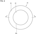
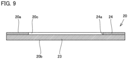
- Fig. 8 is a plan view of current collector 20 of electrochemical cell device 200.
- Fig. 9 is a cross sectional view at IX-IX of Fig. 8 .
- current collector 20 has a metal porous body sheet 23 and a metal porous body sheet 24.
- Metal porous body sheet 23 has a circular shape when viewed in a plan view, for example.
- Metal porous body sheet 24 has an annular shape when viewed in a plan view, for example.
- a through hole 24a is formed in metal porous body sheet 24 so as to extend through metal porous body sheet 24 in the thickness direction of metal porous body sheet 24.
- Through hole 24a is disposed at a position corresponding to recess 20c.
- Metal porous body sheet 23 and metal porous body sheet 24 are disposed to be stacked on each other in the thickness direction of current collector 20.
- Metal porous body sheet 24 is disposed on the main surface 20a side. As a result, through hole 24a and metal porous body sheet 23 constitute recess 20c.
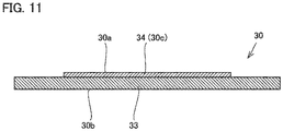
- Fig. 10 is a plan view of current collector 30 of electrochemical cell device 200.
- Fig. 11 is a cross sectional view at XI-XI of Fig. 10 .
- current collector 30 has a metal porous body sheet 33 and a metal porous body sheet 34.
- Each of metal porous body sheet 33 and metal porous body sheet 34 has a circular shape when viewed in a plan view, for example.
- the diameter of metal porous body sheet 33 is larger than the diameter of metal porous body sheet 34.
- Metal porous body sheet 33 and metal porous body sheet 34 are stacked on each other in the thickness direction of current collector 30.
- Metal porous body sheet 34 is disposed on the main surface 30a side so as to correspond to the position of protrusion 30c. As a result, metal porous body sheet 34 constitutes protrusion 30c.
- main surface 20a is provided with recess 20c and main surface 30a has protrusion 30c in electrochemical cell device 200
- main surface 20a is facilitated to conform to the shape of main surface 10a
- main surface 30a is facilitated to conform to the shape of main surface 10b, thereby reducing the spaces between main surface 10a and main surface 20a and between main surface 10b and main surface 30a.
- the contact electrical resistance value between cell 10 and current collector 20 and the contact electrical resistance value between cell 10 and current collector 30 can be decreased, and the output voltage from electrochemical cell device 100 can be improved.
- electrochemical cell device 300 a configuration of an electrochemical cell device (hereinafter, referred to as "electrochemical cell device 300") according to a third embodiment will be described.
- electrochemical cell device 300 a configuration of an electrochemical cell device (hereinafter, referred to as "electrochemical cell device 300") according to a third embodiment will be described.
- electrochemical cell device 300 a configuration of an electrochemical cell device (hereinafter, referred to as "electrochemical cell device 300") according to a third embodiment.
- electrochemical cell device 300 a configuration of an electrochemical cell device (hereinafter, referred to as "electrochemical cell device 300”) according to a third embodiment will be described.
- electrochemical cell device 300 mainly describes differences from the configuration of electrochemical cell device 100, and the same explanation will not be described repeatedly.
- Electrochemical cell device 300 includes a cell 10, a current collector 20, a current collector 30, an interconnector 40, and an interconnector 50.
- Cell 10 is warped to protrude from main surface 10b toward main surface 10a.
- Main surface 20a is provided with a recess 20c, and main surface 30a has a protrusion 30c.
- the configuration of electrochemical cell device 300 is the same as the configuration of electrochemical cell device 100.
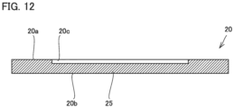
- Fig. 12 is a cross sectional view of current collector 20 of electrochemical cell device 300.
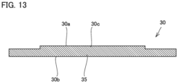
- Fig. 13 is a cross sectional view of current collector 30 of electrochemical cell device 300.
- each of current collector 20 and current collector 30 is constituted of one metal porous body sheet (metal porous body sheet 25 and metal porous body sheet 35).
- each of recess 20c of current collector 20 (metal porous body sheet 25) and protrusion 30c of current collector 30 (metal porous body sheet 35) can be formed by, for example, press working.
- main surface 20a is provided with recess 20c and main surface 30a has protrusion 30c in electrochemical cell device 300
- main surface 20a is facilitated to conform to the shape of main surface 10a
- main surface 30a is facilitated to conform to the shape of main surface 10b, thereby reducing the spaces between main surface 10a and main surface 20a and between main surface 10b and main surface 30a.
- the contact electrical resistance value between cell 10 and current collector 20 and the contact electrical resistance value between cell 10 and current collector 30 are decreased, and the output voltage from electrochemical cell device 100 can be improved.
Landscapes
- Chemical & Material Sciences (AREA)
- Engineering & Computer Science (AREA)
- Chemical Kinetics & Catalysis (AREA)
- Electrochemistry (AREA)
- General Chemical & Material Sciences (AREA)
- Materials Engineering (AREA)
- Metallurgy (AREA)
- Organic Chemistry (AREA)
- Life Sciences & Earth Sciences (AREA)
- Manufacturing & Machinery (AREA)
- Sustainable Development (AREA)
- Sustainable Energy (AREA)
- Ceramic Engineering (AREA)
- Composite Materials (AREA)
- Inorganic Chemistry (AREA)
- Cell Electrode Carriers And Collectors (AREA)
- Fuel Cell (AREA)
Abstract
A electrochemical cell device includes: a cell having a first main surface and a second main surface opposite to the first main surface; a first current collector having a third main surface facing the first main surface; and a second current collector having a fourth main surface facing the second main surface. The cell is warped to protrude from the second main surface toward the first main surface. The third main surface is provided with a recess at a position facing a central portion of the first main surface. The fourth main surface includes a protrusion at a position facing a central portion of the second main surface. Each of the first current collector and the second current collector is constituted of one or more metal porous body sheets each composed of a metal porous body having a framework with a three-dimensional network structure. The central portion of the first main surface includes a portion of the first main surface with a longest distance from a flat reference surface when the cell is placed on the reference surface such that the second main surface faces the reference surface. The central portion of the second main surface includes a portion of the second main surface with a longest distance from the reference surface when the cell is disposed on the reference surface such that the second main surface faces the reference surface.
Description
- The present disclosure relates to an electrochemical cell device. The present application claims a priority based on
Japanese Patent Application No. 2020-072919 filed on April 15, 2020 - PTL 1 (
WO 2019/244480 ) describes a fuel cell. The fuel cell described in PTL 1 includes a solid electrolyte layer, an anode, a cathode, an anode side current collector, and a cathode side current collector. - The anode and the cathode sandwich the solid electrolyte layer (hereinafter, the solid electrolyte layer sandwiched between the anode and the cathode will be referred to as "cell"). The anode side current collector and the cathode side current collector sandwich the cell. Each of the anode side current collector and the cathode side current collector is constituted of a metal porous body sheet composed of a metal porous body having a framework with a three-dimensional network structure.
- PTL 1:
WO 2019/244480 - An electrochemical cell device according to the present disclosure includes: a cell having a first main surface and a second main surface opposite to the first main surface; a first current collector having a third main surface facing the first main surface; and a second current collector having a fourth main surface facing the second main surface. The cell is warped to protrude from the second main surface toward the first main surface. The third main surface is provided with a recess at a position facing a central portion of the first main surface. The fourth main surface includes a protrusion at a position facing a central portion of the second main surface. Each of the first current collector and the second current collector is constituted of one or more metal porous body sheets each composed of a metal porous body having a framework with a three-dimensional network structure. The central portion of the first main surface includes a portion of the first main surface with a longest distance from a flat reference surface when the cell is placed on the reference surface such that the second main surface faces the reference surface. The central portion of the second main surface includes a portion of the second main surface with a longest distance from the reference surface when the cell is disposed on the reference surface such that the second main surface faces the reference surface.
-
-
Fig. 1A is a cross sectional view of anelectrochemical cell device 100. -
Fig. 1B is an enlarged cross sectional view of acell 10. -
Fig. 2 is a plan view ofcell 10. -
Fig. 3 is a schematic cross sectional view showing a shape of warpage ofcell 10. -
Fig. 4 is a plan view of acurrent collector 20. -
Fig. 5 is a cross sectional view at V-V ofFig. 4 . -
Fig. 6 is a plan view of acurrent collector 30. -
Fig. 7 is a cross sectional view at VII-VII ofFig. 6 . -
Fig. 8 is a plan view of acurrent collector 20 of an electrochemical cell device 200. -
Fig. 9 is a cross sectional view at IX-IX ofFig. 8 . -
Fig. 10 is a plan view of acurrent collector 30 of electrochemical cell device 200. -
Fig. 11 is a cross sectional view at XI-XI ofFig. 10 . -
Fig. 12 is a cross sectional view of acurrent collector 20 of an electrochemical cell device 300. -
Fig. 13 is a cross sectional view of acurrent collector 30 of electrochemical cell device 300. - In the fuel cell according to PTL 1, a cell may be warped. When the cell is warped, spaces are formed between the cell and the anode side current collector and between the cell and the cathode side current collector (contact between the cell and each current collector is deteriorated).
- The present disclosure provides an electrochemical cell device to reduce a space between a cell and a current collector.
- According to the electrochemical cell device of the present disclosure, the space between the cell and the current collector can be reduced.
- First, embodiments of the present disclosure are listed and described.
- (1) An electrochemical cell device according to one embodiment includes: a cell having a first main surface and a second main surface opposite to the first main surface; a first current collector having a third main surface facing the first main surface; and a second current collector having a fourth main surface facing the second main surface. The cell is warped to protrude from the second main surface toward the first main surface. The third main surface is provided with a recess at a position facing a central portion of the first main surface. The fourth main surface includes a protrusion at a position facing a central portion of the second main surface. Each of the first current collector and the second current collector is constituted of one or more metal porous body sheets each composed of a metal porous body having a framework with a three-dimensional network structure. The central portion of the first main surface includes a portion of the first main surface with a longest distance from a flat reference surface when the cell is placed on the reference surface such that the second main surface faces the reference surface. The central portion of the second main surface includes a portion of the second main surface with a longest distance from the reference surface when the cell is disposed on the reference surface such that the second main surface faces the reference surface.
According to the electrochemical cell device of (1), a space between the cell and each current collector can be reduced. - (2) In the electrochemical cell device of (1), the one or more metal porous body sheets of the first current collector may be a first metal porous body sheet and a second metal porous body sheet. The first metal porous body sheet and the second metal porous body sheet may be disposed side by side in a plane orthogonal to a thickness direction of the first current collector. A first through hole may be formed in the second metal porous body sheet at a position corresponding to the recess so as to extend through the second metal porous body sheet in a thickness direction of the second metal porous body sheet. The first metal porous body sheet may be disposed in the first through hole. A thickness of the second metal porous body sheet may be more than a thickness of the first metal porous body sheet. The recess may be defined by an inner peripheral surface of the first through hole and a main surface of the first metal porous body sheet.
According to the electrochemical cell device of (2), the space between the cell and the current collector can be reduced. - (3) In the electrochemical cell device of (2), a value obtained by subtracting the thickness of the first metal porous body sheet from the thickness of the second metal porous body sheet may be equal to a warpage amount of the cell.
According to the electrochemical cell device of (3), the space between the cell and the current collector can be further reduced. - (4) In the electrochemical cell device of (1), the one or more metal porous body sheets of the first current collector may be a first metal porous body sheet and a second metal porous body sheet. The first metal porous body sheet and the second metal porous body sheet may be disposed to be stacked on each other such that the second metal porous body sheet is located on the third main surface side in a thickness direction of the first current collector. A first through hole may be formed in the second metal porous body sheet at a position corresponding to the recess so as to extend through the second metal porous body sheet in a thickness direction of the second metal porous body sheet.
- (5) In the electrochemical cell device of any one of (1) to (4), the one or more metal porous body sheets of the second current collector may be a third metal porous body sheet and a fourth metal porous body sheet. The third metal porous body sheet and the fourth metal porous body sheet may be disposed side by side in a plane orthogonal to a thickness direction of the second current collector. A second through hole may be formed in the fourth metal porous body sheet at a position corresponding to the protrusion so as to extend through the fourth metal porous body sheet in a thickness direction of the fourth metal porous body sheet. The third metal porous body sheet may be disposed in the second through hole. A thickness of the third metal porous body sheet may be more than a thickness of the fourth metal porous body sheet.
According to the electrochemical cell device of (5), the space between the cell and the current collector can be reduced. - (6) In the electrochemical cell device of (1) to (4), a value obtained by subtracting the thickness of the fourth metal porous body sheet from the thickness of the third metal porous body sheet may be equal to a warpage amount of the cell.
According to the electrochemical cell device of (6), the space between the cell and the current collector can be further reduced. - (7) In the electrochemical cell device of any one of (1) to (4), the one or more metal porous body sheets of the second current collector may be a third metal porous body sheet and a fourth metal porous body sheet. The third metal porous body sheet and the fourth metal porous body sheet may be disposed to be stacked on each other such that the fourth metal porous body sheet is located on the fourth main surface side in a thickness direction of the second current collector. The fourth metal porous body sheet may constitute the protrusion.
According to the electrochemical cell device of (7), the space between the cell and the current collector can be reduced. - (8) In the electrochemical cell device of (1) to (7), the first current collector may be a cathode side current collector, and the second current collector may be an anode side current collector.
According to the electrochemical cell device of (8), the space between the cell and the current collector can be reduced. - (9) In the electrochemical cell device of (8), the framework of each of the one or more metal porous body sheets of the first current collector may contain nickel and cobalt. A coating weight of each of the one or more metal porous body sheets of the first current collector may be 900 g/m2 or less.
According to the electrochemical cell device of (9), the space between the cell and the current collector can be reduced. - (10) In the electrochemical cell device of (8), the framework of each of the one or more metal porous body sheets of the second current collector may contain nickel. A coating weight of each of the one or more metal porous body sheets of the second current collector may be 1000 g/m2 or less.
- (11) In the electrochemical cell device according to (1) to (10), a value obtained by dividing a warpage amount of the cell by a maximum width of the cell when viewed in a plan view may be 1/1000 or more.
According to the electrochemical cell device of (11), even when the warpage of the cell is large, the space between the cell and the current collector can be reduced. - (12) The electrochemical cell device of (1) to (11) may be a solid oxide fuel cell.
According to the electrochemical cell device of (12), contact between the cell and the current collector can be improved, thus resulting in increased output voltage in the solid oxide fuel cell. - (13) The electrochemical cell device of (1) to (11) may be a solid oxide electrolysis cell.
According to the electrochemical cell device of (13), contact between the cell and the current collector can be improved, thus resulting in lowered electrolytic voltage in the solid oxide electrolysis cell. - Next, embodiments of the present disclosure will be described with reference to figures. Here, the same or corresponding portions are denoted by the same reference characters, and the same explanation will not be described repeatedly.
- Hereinafter, a configuration of an electrochemical cell device (hereinafter, referred to as "
electrochemical cell device 100") according to a first embodiment will be described. -
Electrochemical cell device 100 is a solid oxide fuel cell (SOFC). Althoughelectrochemical cell device 100 may be a solid oxide electrolysis cell (SOEC), the SOFC will be described below as an exemplaryelectrochemical cell device 100. -
Fig. 1A is a cross sectional view ofelectrochemical cell device 100.Fig. 1A shows a structure of a single-cell included inelectrochemical cell device 100.Electrochemical cell device 100 is formed by stacking a plurality of single-cell structures. Further,Fig. 1A does not illustrate warpage of acell 10, arecess 20c, and aprotrusion 30c, which will be described later.Fig. 1B is an enlarged cross sectional view ofcell 10. As shown inFigs. 1A and1B ,electrochemical cell device 100 includescell 10, acurrent collector 20, acurrent collector 30, aninterconnector 40, and aninterconnector 50. -
Cell 10 has amain surface 10a and amain surface 10b.Main surface 10b is a surface opposite tomain surface 10a.Cell 10 includes asolid electrolyte layer 11, acathode 12, ananode 13, and anintermediate layer 14. -
Solid electrolyte layer 11 is a layer composed of a solid electrolyte. For example,solid electrolyte layer 11 is composed of an oxide (YSZ) of zirconium (Zr) doped with yttrium (Y).Cathode 12 is composed of, for example, LSC (oxide of lanthanum (La) strontium (Sr) cobalt (Co)).Anode 13 is composed of, for example, a mixture of YSZ and an oxide of nickel (Ni2O).Intermediate layer 14 is composed of, for example, an oxide (GDC) of cerium (Ce) doped with gadolinium (Gd). -
Cathode 12 constitutes amain surface 10a ofcell 10.Anode 13 constitutes amain surface 10b ofcell 10.Solid electrolyte layer 11 is disposed betweencathode 12 andanode 13.Intermediate layer 14 is disposed betweensolid electrolyte layer 11 andcathode 12.Solid electrolyte layer 11 andanode 13 are in contact with each other. -
Fig. 2 is a plan view ofcell 10. As shown inFig. 2 ,cell 10 has a circular shape when viewed in a plan view. However, the planar shape ofcell 10 is not limited thereto.Cell 10 may have a quadrangular shape when viewed in a plan view. -
Fig. 3 is a schematic cross sectional view showing a shape of warpage ofcell 10. As shown inFig. 3 ,cell 10 is warped. For example,cell 10 is warped to protrude from themain surface 10b side toward themain surface 10a side. A warpage amount of cell 10 (hereinafter, referred to as "warpage amount WA") is, for example, 100 µm or more. Warpage amount WA may be 1000 µm or more. - Warpage amount WA is measured by the following method. First,
cell 10 is placed on a flat reference surface. Second, LK-G35 provided by Keyence is used to measure a distance (hereinafter, referred to as "distance L") between the reference surface and a position (hereinafter, referred to as "apex P") onmain surface 10a with the longest distance from the reference surface. Apex P is located at the central portion of cell 10 (the central portion ofmain surface 10a) when viewed in a plan view. Third, the thickness of cell 10 (hereinafter, referred to as "thickness T") is subtracted from distance L. In this way, warpage amount WA is measured. - The maximum width of
cell 10 when viewed in a plan view is defined as a width Wmax (seeFig. 2 ). A value obtained by dividing warpage amount WA by width Wmax is, for example, 1/1000 or more. The value obtained by dividing warpage amount WA by width Wmax may be 1/100 or more. When the planar shape ofcell 10 is a circular shape, width Wmax is equal to the diameter of the circular shape. When the planar shape of the cell is a quadrangular shape, width Wmax is equal to the length of the diagonal of the quadrangular shape. - As shown in
Fig. 1A ,current collector 20 is disposed onmain surface 10a, andcurrent collector 30 is disposed onmain surface 10b. From another viewpoint, it can be said thatcell 10 is sandwiched betweencurrent collector 20 andcurrent collector 30.Current collector 20 is a cathode side current collector, andcurrent collector 30 is an anode side current collector. -
Current collector 20 has amain surface 20a and amain surface 20b.Main surface 20a facesmain surface 10a.Main surface 20b is a surface opposite tomain surface 20a.Fig. 4 is a plan view ofcurrent collector 20.Fig. 5 is a cross sectional view at V-V ofFig. 4 . As shown inFigs. 4 and5 ,main surface 20a is provided withrecess 20c.Main surface 20a is depressed toward themain surface 20b side inrecess 20c.Recess 20c is disposed at a position facing the central portion ofmain surface 10a. -
Current collector 20 is constituted of a metalporous body sheet 21 and a metalporous body sheet 22. Each of metalporous body sheet 21 and metalporous body sheet 22 is composed of a metal porous body having a framework with a three-dimensional network structure. - The framework of the metal porous body of each of metal
porous body sheet 21 and metalporous body sheet 22 contains, for example, nickel (Ni) and cobalt. The coating weight of each of metalporous body sheet 21 and metalporous body sheet 22 is preferably 900 g/m2 or less. The coating weight of metal porous body sheet 21 (metal porous body sheet 22) is a value obtained by dividing the weight of metal porous body sheet 21 (metal porous body sheet 22) by the area of the main surface of metal porous body sheet 21 (metal porous body sheet 22). -
Current collector 20 has a circular shape when viewed in a plan view. Metalporous body sheet 21 has a circular shape when viewed in a plan view. Metalporous body sheet 22 has an annular shape when viewed in a plan view. That is, a throughhole 22a is formed in metalporous body sheet 22 so as to extend through metalporous body sheet 22 in the thickness direction of metalporous body sheet 22. Throughhole 22a is formed at a position corresponding to recess 20c. - The thickness (hereinafter, referred to as "thickness T2") of metal
porous body sheet 22 is larger than the thickness (hereinafter, referred to as "thickness T1 ") of metalporous body sheet 21. Metalporous body sheet 21 and metalporous body sheet 22 are disposed side by side (disposed not to be stacked on each other) in a plane orthogonal to the thickness direction ofcurrent collector 20. Metalporous body sheet 21 is disposed in throughhole 22a. Therefore, metalporous body sheet 21 and throughhole 22a constituterecess 20c. -
Current collector 30 has amain surface 30a and amain surface 30b.Main surface 30a facesmain surface 10b.Main surface 30b is a surface opposite tomain surface 30a.Fig. 6 is a plan view ofcurrent collector 30.Fig. 7 is a cross sectional view at VII-VII ofFig. 6 . As shown inFigs. 6 and7 ,main surface 30a has aprotrusion 30c. Atprotrusion 30c,main surface 30a protrudes opposite tomain surface 30b.Protrusion 30c is disposed at a position facing the central portion ofmain surface 10b. -
Current collector 30 is constituted of a metalporous body sheet 31 and a metalporous body sheet 32. Each of metalporous body sheet 31 and metalporous body sheet 32 is constituted of a metal porous body having a framework with a three-dimensional network structure. - The framework of the metal porous body of each of metal
porous body sheet 31 and metalporous body sheet 32 contains, for example, nickel. The coating weight of each of metalporous body sheet 31 and metalporous body sheet 32 is preferably 1000 g/m2 or less. The coating weight of metal porous body sheet 31 (metal porous body sheet 32) is a value obtained by dividing the weight of metal porous body sheet 31 (metal porous body sheet 32) by the area of the main surface of metal porous body sheet 31 (metal porous body sheet 32). -
Current collector 30 has a circular shape when viewed in a plan view. Metalporous body sheet 31 has a circular shape when viewed in a plan view. Metalporous body sheet 32 has an annular shape when viewed in a plan view. That is, a throughhole 32a is formed in metalporous body sheet 32 so as to extend through metalporous body sheet 32 in the thickness direction of metalporous body sheet 32. Throughhole 32a is formed at a position corresponding toprotrusion 30c. - The thickness (hereinafter, referred to as "thickness T3") of metal
porous body sheet 31 is larger than the thickness (hereinafter, referred to as "thickness T4") of metalporous body sheet 32. Metalporous body sheet 31 and metalporous body sheet 32 are disposed side by side (disposed not to be stacked on each other) in a plane orthogonal to the thickness direction ofcurrent collector 30. Metalporous body sheet 31 is disposed in throughhole 32a. Therefore, metalporous body sheet 31 constitutesprotrusion 30c. - A value obtained by subtracting thickness T1 from thickness T2 is preferably equal to warpage amount WA. A value obtained by subtracting thickness T4 from thickness T3 is preferably equal to warpage amount WA. It should be noted that a case where the value obtained by subtracting thickness T1 from thickness T2 falls within a range of 0.95 time or more and 1.05 times or less as large as warpage amount WA is included in the case where "the value obtained by subtracting thickness T1 from thickness T2 is equal to warpage amount WA", and a case where the value obtained by subtracting thickness T4 from thickness T3 falls within a range of 0.95 time or more and 1.05 times or less as large as warpage amount WA is included in the case where "the value obtained by subtracting thickness T4 from thickness T3 is equal to warpage amount WA".
- Metal
porous body sheet 22 may be concentrically divided into a plurality of metal porous body sheets. In this case, a metal porous body sheet disposed on an outer side is thicker. Metalporous body sheet 32 may be concentrically divided into a plurality of metal porous body sheets. In this case, a metal porous body sheet disposed on an outer side is thinner. - As shown in
Fig. 1A ,interconnector 40 is disposed onmain surface 20b andinterconnector 50 is disposed onmain surface 30b. From another viewpoint, it can be said thatcell 10,current collector 20, andcurrent collector 30 are sandwiched betweeninterconnector 40 andinterconnector 50. Agroove 41 is formed in the main surface ofinterconnector 40 on thecurrent collector 20 side, and agroove 51 is formed in the main surface ofinterconnector 50 on thecurrent collector 30 side. Each ofinterconnector 40 andinterconnector 50 is composed of an electrically conductive material. - Hereinafter, effects of
electrochemical cell device 100 will be described. - In
electrochemical cell device 100, sincecell 10 is warped to protrude frommain surface 10b towardmain surface 10a, spaces are formed betweenmain surface 10a andmain surface 20a and betweenmain surface 10b andmain surface 30a whenmain surface 20a andmain surface 30a are flat. This results in an increased contact electrical resistance value betweencell 10 andcurrent collector 20, an increased contact electrical resistance value betweencell 10 andcurrent collector 30, and a decreased output voltage fromelectrochemical cell device 100. - However, in
electrochemical cell device 100, sincemain surface 20a is provided withrecess 20c andmain surface 30a hasprotrusion 30c,main surface 20a is facilitated to conform to the shape ofmain surface 10a andmain surface 30a is facilitated to conform to the shape ofmain surface 10b, thereby reducing the spaces betweenmain surface 10a andmain surface 20a and betweenmain surface 10b andmain surface 30a. - Therefore, according to
electrochemical cell device 100, the contact electrical resistance value betweencell 10 andcurrent collector 20 and the contact electrical resistance value betweencell 10 andcurrent collector 30 can be decreased, and the output voltage fromelectrochemical cell device 100 can be improved. - It should be noted that when
electrochemical cell device 100 is an SOEC, the contact electrical resistance value betweencell 10 andcurrent collector 20 and the contact electrical resistance value betweencell 10 andcurrent collector 30 are decreased, with the result that the electrolytic voltage inelectrochemical cell device 100 can be lowered. - When the framework of the metal porous body of each of metal
porous body sheet 21 and metalporous body sheet 22 contains nickel and cobalt and the coating weight of the metal porous body of each of metalporous body sheet 21 and metalporous body sheet 22 is 900 g/m2 or less, deformability of each of metalporous body sheet 21 and metalporous body sheet 22 can be ensured, so thatmain surface 20a is more facilitated to conform to the shape ofmain surface 10a. - When the framework of the metal porous body of each of metal
porous body sheet 31 and metalporous body sheet 32 contains nickel and the coating weight of the metal porous body of each of metalporous body sheet 31 and metalporous body sheet 32 is 900 g/m2 or less, deformability of each of metalporous body sheet 31 and metalporous body sheet 32 can be ensured, so thatmain surface 30a is more facilitated to conform to the shape ofmain surface 10b. - Hereinafter, a power generation test performed to confirm the effects of
electrochemical cell device 100 will be described. - Electrochemical cells of samples 1 to 6 were provided for a power generation test. In each of samples 1 to 6, the shapes of
cell 10,current collector 20, andcurrent collector 30 were as shown in Table 1. It should be noted that although not shown in Table 1, in each of samples 1 to 6, the thickness and diameter ofcell 10 were 0.4 mm and 100 mm, respectively.[Table 1] Warpage Amount WA Current Collector 20 Current Collector 30 Sample 1 100 µm Metal Porous Body Sheet 21 (Thickness T1 = 400 µm) + Metal Porous Body Sheet 22 (Thickness T2 = 500 µm) Metal Porous Body Sheet 31 (Thickness T3 = 500 µm) + Metal Porous Body Sheet 32 (Thickness T4 = 400 µm) Sample 2 300 µm Metal Porous Body Sheet 21 (Thickness T1 = 200 µm) + Metal Porous Body Sheet 22 (Thickness T2 = 500 µm) Metal Porous Body Sheet 31 (Thickness T3 = 500 µm) + Metal Porous Body Sheet 32 (Thickness T4 = 200 µm) Sample 3 1000 µm Metal Porous Body Sheet 21 (Thickness T1 = 100 µm) + Metal Porous Body Sheet 22 (Thickness T2 = 1100 µm) Metal Porous Body Sheet 31 (Thickness T3 = 1100 µm) + Metal Porous Body Sheet 32 (Thickness T4 = 100 µm) Sample 4 2000 µm Metal Porous Body Sheet 21 (Thickness T1 = 100 µm) + Metal Porous Body Sheet 22 (Thickness T2 = 2100 µm) Metal Porous Body Sheet 31 (Thickness T3 = 2100 µm) + Metal Porous Body Sheet 32 (Thickness T4 = 100 µm) Sample 5 100 µm One Metal Porous Body Sheet Having Thickness of 500 µm One Metal Porous Body Sheet Having Thickness of 500 µm Sample 6 1000 µm One Metal Porous Body Sheet Having Thickness of 1100 µm One Metal Porous Body Sheet Having Thickness of 1100 µm - As shown in Table 1, in each of samples 1 and 5, warpage amount WA was 100 µm. In sample 2, warpage amount WA was 300 µm. In each of samples 3 and 6, warpage amount WA was 1000 µm. In sample 4, warpage amount WA was 2000 µm.
- In sample 1, a metal
porous body sheet 21 having a thickness of 400 µm and a metalporous body sheet 22 having a thickness of 500 µm were used ascurrent collector 20, and a metalporous body sheet 31 having a thickness of 500 µm and a metalporous body sheet 32 having a thickness of 400 µm were used ascurrent collector 30. - In sample 2, a metal
porous body sheet 21 having a thickness of 200 µm and a metalporous body sheet 22 having a thickness of 500 µm were used ascurrent collector 20, and a metalporous body sheet 31 having a thickness of 500 µm and a metalporous body sheet 32 having a thickness of 200 µm were used ascurrent collector 30. - In sample 3, a metal
porous body sheet 21 having a thickness of 100 µm and a metalporous body sheet 22 having a thickness of 1100 µm were used ascurrent collector 20, and a metalporous body sheet 31 having a thickness of 1100 µm and a metalporous body sheet 32 having a thickness of 100 µm were used ascurrent collector 30. - In sample 4, a metal
porous body sheet 21 having a thickness of 100 µm and a metalporous body sheet 22 having a thickness of 2100 µm were used ascurrent collector 20, and a metalporous body sheet 31 having a thickness of 2100 µm and a metalporous body sheet 32 having a thickness of 100 µm were used ascurrent collector 30. - In sample 5, one metal porous body sheet having a thickness of 500 µm was used as
current collector 20, and one metal porous body sheet having a thickness of 500 µm was used ascurrent collector 30. - In sample 6, one metal porous body sheet having a thickness of 1100 µm was used as
current collector 20, and one metal porous body sheet having a thickness of 1100 µm was used ascurrent collector 30. - Table 2 shows an initial value of an output voltage between the anode and the cathode when a current of 0.5 A/cm2 flows between the anode and the cathode at 750°C.
[Table 2] Output Voltage Sample 1 0.85 V Sample 2 0.86 V Sample 3 0.89 V Sample 4 0.90 V Sample 5 0.78 V Sample 6 0.70 V - As shown in Table 2, the output voltage of sample 1 was more than the output voltage of sample 5. The output voltage of sample 3 was more than the output voltage of sample 6.
- In view of these comparisons, it was also experimentally revealed that since
main surface 20a ofcurrent collector 20 is provided withrecess 20c andmain surface 30a ofcurrent collector 30 hasprotrusion 30c, the space betweencell 10 andcurrent collector 20 and the space betweencell 10 andcurrent collector 30 can be decreased and the output voltage fromelectrochemical cell device 100 can be increased. - As warpage amount WA is larger, the spaces are more likely to be formed between
cell 10 andcurrent collector 20 and betweencell 10 andcurrent collector 30, but a surface area ofcell 10 contributing to an electrochemical reaction is increased. - The output voltage of sample 6 was less than the output voltage of sample 5. This is presumably due to the following reason: since warpage amount WA of sample 6 was more than warpage amount WA of sample 5, the space between
cell 10 andcurrent collector 20 and the space betweencell 10 andcurrent collector 30 were increased, thereby increasing the contact electrical resistance betweencell 10 andcurrent collector 20 and the contact electrical resistance betweencell 10 andcurrent collector 30. - On the other hand, in each of samples 1 to 4, as warpage amount WA was larger, the output voltage was increased. In each of samples 1 to 4, each of the value obtained by subtracting thickness T1 from thickness T2 and the value obtained by subtracting thickness T4 from thickness T3 coincided with warpage amount WA.
- In view of this, it was experimentally revealed that by increasing warpage amount WA while each of the value obtained by subtracting thickness T1 from thickness T2 and the value obtained by subtracting thickness T4 from thickness T3 coincides with warpage amount WA, the surface area of
cell 10 contributing to the electrochemical reaction can be increased, in other words, the output voltage fromelectrochemical cell device 100 can be further increased, while reducing the space betweencell 10 andcurrent collector 20 and the space betweencell 10 andcurrent collector 30. - Hereinafter, a configuration of an electrochemical cell device (hereinafter, referred to as "electrochemical cell device 200") according to a second embodiment will be described. Here, the following mainly describes differences from the configuration of
electrochemical cell device 100, and the same explanation will not be described repeatedly. - Electrochemical cell device 200 includes a
cell 10, acurrent collector 20, acurrent collector 30, aninterconnector 40, and aninterconnector 50.Cell 10 is warped to protrude frommain surface 10b towardmain surface 10a.Main surface 20a is provided with arecess 20c, andmain surface 30a has aprotrusion 30c. Regarding these points, the configuration of electrochemical cell device 200 is the same as the configuration ofelectrochemical cell device 100. -
Fig. 8 is a plan view ofcurrent collector 20 of electrochemical cell device 200.Fig. 9 is a cross sectional view at IX-IX ofFig. 8 . As shown inFigs. 8 and9 , in electrochemical cell device 200,current collector 20 has a metalporous body sheet 23 and a metalporous body sheet 24. Metalporous body sheet 23 has a circular shape when viewed in a plan view, for example. Metalporous body sheet 24 has an annular shape when viewed in a plan view, for example. - A through
hole 24a is formed in metalporous body sheet 24 so as to extend through metalporous body sheet 24 in the thickness direction of metalporous body sheet 24. Throughhole 24a is disposed at a position corresponding to recess 20c. Metalporous body sheet 23 and metalporous body sheet 24 are disposed to be stacked on each other in the thickness direction ofcurrent collector 20. Metalporous body sheet 24 is disposed on themain surface 20a side. As a result, throughhole 24a and metalporous body sheet 23 constituterecess 20c. -
Fig. 10 is a plan view ofcurrent collector 30 of electrochemical cell device 200.Fig. 11 is a cross sectional view at XI-XI ofFig. 10 . As shown inFigs. 10 and11 ,current collector 30 has a metalporous body sheet 33 and a metalporous body sheet 34. Each of metalporous body sheet 33 and metalporous body sheet 34 has a circular shape when viewed in a plan view, for example. The diameter of metalporous body sheet 33 is larger than the diameter of metalporous body sheet 34. - Metal
porous body sheet 33 and metalporous body sheet 34 are stacked on each other in the thickness direction ofcurrent collector 30. Metalporous body sheet 34 is disposed on themain surface 30a side so as to correspond to the position ofprotrusion 30c. As a result, metalporous body sheet 34 constitutesprotrusion 30c. - Hereinafter, effects of electrochemical cell device 200 will be described.
- As with
electrochemical cell device 100, sincemain surface 20a is provided withrecess 20c andmain surface 30a hasprotrusion 30c in electrochemical cell device 200,main surface 20a is facilitated to conform to the shape ofmain surface 10a andmain surface 30a is facilitated to conform to the shape ofmain surface 10b, thereby reducing the spaces betweenmain surface 10a andmain surface 20a and betweenmain surface 10b andmain surface 30a. As a result, according to electrochemical cell device 200, the contact electrical resistance value betweencell 10 andcurrent collector 20 and the contact electrical resistance value betweencell 10 andcurrent collector 30 can be decreased, and the output voltage fromelectrochemical cell device 100 can be improved. - Hereinafter, a configuration of an electrochemical cell device (hereinafter, referred to as "electrochemical cell device 300") according to a third embodiment will be described. Here, the following mainly describes differences from the configuration of
electrochemical cell device 100, and the same explanation will not be described repeatedly. - Electrochemical cell device 300 includes a
cell 10, acurrent collector 20, acurrent collector 30, aninterconnector 40, and aninterconnector 50.Cell 10 is warped to protrude frommain surface 10b towardmain surface 10a.Main surface 20a is provided with arecess 20c, andmain surface 30a has aprotrusion 30c. Regarding these points, the configuration of electrochemical cell device 300 is the same as the configuration ofelectrochemical cell device 100. -
Fig. 12 is a cross sectional view ofcurrent collector 20 of electrochemical cell device 300.Fig. 13 is a cross sectional view ofcurrent collector 30 of electrochemical cell device 300. As shown inFigs. 12 and13 , each ofcurrent collector 20 andcurrent collector 30 is constituted of one metal porous body sheet (metalporous body sheet 25 and metal porous body sheet 35). - It should be noted that each of
recess 20c of current collector 20 (metal porous body sheet 25) andprotrusion 30c of current collector 30 (metal porous body sheet 35) can be formed by, for example, press working. - Hereinafter, effects of electrochemical cell device 300 will be described.
- As with
electrochemical cell device 100, sincemain surface 20a is provided withrecess 20c andmain surface 30a hasprotrusion 30c in electrochemical cell device 300,main surface 20a is facilitated to conform to the shape ofmain surface 10a andmain surface 30a is facilitated to conform to the shape ofmain surface 10b, thereby reducing the spaces betweenmain surface 10a andmain surface 20a and betweenmain surface 10b andmain surface 30a. As a result, according to electrochemical cell device 300, the contact electrical resistance value betweencell 10 andcurrent collector 20 and the contact electrical resistance value betweencell 10 andcurrent collector 30 are decreased, and the output voltage fromelectrochemical cell device 100 can be improved. - The embodiments disclosed herein are illustrative and non-restrictive in any respect. The scope of the present invention is defined by the terms of the claims, rather than the embodiments described above, and is intended to include any modifications within the scope and meaning equivalent to the terms of the claims.
- 10: cell; 10a, 10b: main surface; 11: solid electrolyte layer; 12: cathode; 13: anode; 14: intermediate layer; 20: current collector; 20a, 20b: main surface; 20c: recess; 21: metal porous body sheet; 22: metal porous body sheet; 22a: through hole; 23: metal porous body sheet; 24: metal porous body sheet; 24a: through hole; 25: metal porous body sheet; 30: current collector; 30a: main surface; 30b: main surface; 30c: protrusion; 31: metal porous body sheet; 32: metal porous body sheet; 32a: through hole; 33, 34, 35: metal porous body sheet; 40: interconnector; 41: groove; 50: interconnector; 51: groove; 100, 200, 300: electrochemical cell device; L: distance; P: apex; T, T1, T2, T3, T4: thickness; WA: warpage amount; Wmax: width.
Claims (13)
- A electrochemical cell device comprising:a cell having a first main surface and a second main surface opposite to the first main surface;a first current collector having a third main surface facing the first main surface; anda second current collector having a fourth main surface facing the second main surface, whereinthe cell is warped to protrude from the second main surface toward the first main surface,the third main surface is provided with a recess at a position facing a central portion of the first main surface,the fourth main surface includes a protrusion at a position facing a central portion of the second main surface,each of the first current collector and the second current collector is constituted of one or more metal porous body sheets each composed of a metal porous body having a framework with a three-dimensional network structure,the central portion of the first main surface includes a portion of the first main surface with a longest distance from a flat reference surface when the cell is placed on the reference surface such that the second main surface faces the reference surface, andthe central portion of the second main surface includes a portion of the second main surface with a longest distance from the reference surface when the cell is disposed on the reference surface such that the second main surface faces the reference surface.
- The electrochemical cell device according to claim 1, whereinthe one or more metal porous body sheets of the first current collector are a first metal porous body sheet and a second metal porous body sheet,the first metal porous body sheet and the second metal porous body sheet are disposed side by side in a plane orthogonal to a thickness direction of the first current collector,a first through hole is formed in the second metal porous body sheet at a position corresponding to the recess so as to extend through the second metal porous body sheet in a thickness direction of the second metal porous body sheet,the first metal porous body sheet is disposed in the first through hole,a thickness of the second metal porous body sheet is more than a thickness of the first metal porous body sheet, andthe recess is defined by an inner peripheral surface of the first through hole and a main surface of the first metal porous body sheet.
- The electrochemical cell device according to claim 2, wherein a value obtained by subtracting the thickness of the first metal porous body sheet from the thickness of the second metal porous body sheet is equal to a warpage amount of the cell.
- The electrochemical cell device according to claim 1, whereinthe one or more metal porous body sheets of the first current collector are a first metal porous body sheet and a second metal porous body sheet,the first metal porous body sheet and the second metal porous body sheet are disposed to be stacked on each other such that the second metal porous body sheet is located on the third main surface side in a thickness direction of the first current collector, anda first through hole is formed in the second metal porous body sheet at a position corresponding to the recess so as to extend through the second metal porous body sheet in a thickness direction of the second metal porous body sheet.
- The electrochemical cell device according to any one of claims 1 to 4, whereinthe one or more metal porous body sheets of the second current collector are a third metal porous body sheet and a fourth metal porous body sheet,the third metal porous body sheet and the fourth metal porous body sheet are disposed side by side in a plane orthogonal to a thickness direction of the second current collector,a second through hole is formed in the fourth metal porous body sheet at a position corresponding to the protrusion so as to extend through the fourth metal porous body sheet in a thickness direction of the fourth metal porous body sheet,the third metal porous body sheet is disposed in the second through hole, anda thickness of the third metal porous body sheet is more than a thickness of the fourth metal porous body sheet.
- The electrochemical cell device according to claim 5, wherein a value obtained by subtracting the thickness of the fourth metal porous body sheet from the thickness of the third metal porous body sheet is equal to a warpage amount of the cell.
- The electrochemical cell device according to any one of claims 1 to 4, whereinthe one or more metal porous body sheets of the second current collector are a third metal porous body sheet and a fourth metal porous body sheet,the third metal porous body sheet and the fourth metal porous body sheet are disposed to be stacked on each other such that the fourth metal porous body sheet is located on the fourth main surface side in a thickness direction of the second current collector, andthe fourth metal porous body sheet constitutes the protrusion.
- The electrochemical cell device according to any one of claims 1 to 7, whereinthe first current collector is a cathode side current collector, andthe second current collector is an anode side current collector.
- The electrochemical cell device according to claim 8, whereinthe framework of each of the one or more metal porous body sheets of the first current collector contains nickel and cobalt, anda coating weight of each of the one or more metal porous body sheets of the first current collector is 900 g/m2 or less.
- The electrochemical cell device according to claim 8 or 9, wherein the framework of each of the one or more metal porous body sheets of the second current collector contains nickel, and
a coating weight of each of the one or more metal porous body sheets of the second current collector is 1000 g/m2 or less. - The electrochemical cell device according to any one of claims 1 to 10, wherein a value obtained by dividing a warpage amount of the cell by a maximum width of the cell when viewed in a plan view is 1/1000 or more.
- The electrochemical cell device according to any one of claims 1 to 11, wherein the electrochemical cell device is a solid oxide fuel cell.
- The electrochemical cell device according to any one of claims 1 to 11, wherein the electrochemical cell device is a solid oxide electrolysis cell.
Applications Claiming Priority (2)
| Application Number | Priority Date | Filing Date | Title |
|---|---|---|---|
| JP2020072919 | 2020-04-15 | ||
| PCT/JP2021/001578 WO2021210231A1 (en) | 2020-04-15 | 2021-01-19 | Electrochemical cell device |
Publications (1)
| Publication Number | Publication Date |
|---|---|
| EP4138162A1 true EP4138162A1 (en) | 2023-02-22 |
Family
ID=78084196
Family Applications (1)
| Application Number | Title | Priority Date | Filing Date |
|---|---|---|---|
| EP21787933.7A Pending EP4138162A1 (en) | 2020-04-15 | 2021-01-19 | Electrochemical cell device |
Country Status (5)
| Country | Link |
|---|---|
| US (1) | US20230135982A1 (en) |
| EP (1) | EP4138162A1 (en) |
| JP (1) | JPWO2021210231A1 (en) |
| CN (1) | CN115336052A (en) |
| WO (1) | WO2021210231A1 (en) |
Family Cites Families (6)
| Publication number | Priority date | Publication date | Assignee | Title |
|---|---|---|---|---|
| JP2005317241A (en) * | 2004-04-27 | 2005-11-10 | Tokyo Gas Co Ltd | Supporting film type solid oxide fuel cell stack, and manufacturing method of the same |
| JP2006260994A (en) * | 2005-03-17 | 2006-09-28 | Toyota Motor Corp | Fuel cell |
| JP2010015977A (en) * | 2008-06-03 | 2010-01-21 | Honda Motor Co Ltd | Fuel cell and method of producing the fuel cell |
| JP2013069521A (en) * | 2011-09-22 | 2013-04-18 | Nissan Motor Co Ltd | Fuel cell, fuel cell stack, and manufacturing method for fuel cell or fuel cell stack |
| CN110856447B (en) | 2018-06-21 | 2021-08-27 | 住友电气工业株式会社 | Porous body, current collector including the same, and fuel cell |
| JP2020072919A (en) | 2019-11-08 | 2020-05-14 | 株式会社ユニバーサルエンターテインメント | Game machine |
-
2021
- 2021-01-19 WO PCT/JP2021/001578 patent/WO2021210231A1/en unknown
- 2021-01-19 CN CN202180025442.XA patent/CN115336052A/en active Pending
- 2021-01-19 EP EP21787933.7A patent/EP4138162A1/en active Pending
- 2021-01-19 US US17/914,801 patent/US20230135982A1/en active Pending
- 2021-01-19 JP JP2022515207A patent/JPWO2021210231A1/ja active Pending
Also Published As
| Publication number | Publication date |
|---|---|
| WO2021210231A1 (en) | 2021-10-21 |
| JPWO2021210231A1 (en) | 2021-10-21 |
| US20230135982A1 (en) | 2023-05-04 |
| CN115336052A (en) | 2022-11-11 |
Similar Documents
| Publication | Publication Date | Title |
|---|---|---|
| US10665870B2 (en) | Electrochemical reaction unit and fuel cell stack | |
| MX2007001511A (en) | Resistive-varying electrode structure. | |
| US10361440B2 (en) | Electrochemical reaction unit having a single cell including a current collector having a protrusion coated with an electrically conductive coat in contact with a cathode via a bonding layer and fuel cell stack | |
| US20140017597A1 (en) | Fuel cell | |
| US8580453B2 (en) | Electrode-supported ceramic fuel cell containing laminar composite electrode including porous support electrode, patterned structure layer and electrolyte | |
| KR102239403B1 (en) | Electrochemical reaction single cell and electrochemical reaction cell stack | |
| KR102169225B1 (en) | Electrochemical reaction single cell and electrochemical reaction cell stack | |
| EP2693545B1 (en) | Fuel cell | |
| EP4138162A1 (en) | Electrochemical cell device | |
| KR102241562B1 (en) | Electrochemical reaction single cell and electrochemical reaction cell stack | |
| US20140017598A1 (en) | Fuel cell | |
| JP7349846B2 (en) | Electrochemical cell, electrochemical reaction cell stack | |
| EP3499616B1 (en) | Electrochemical reaction single cell and electrochemical reaction cell stack | |
| JP7349847B2 (en) | Electrochemical cell, electrochemical reaction cell stack | |
| JP2948441B2 (en) | Flat solid electrolyte fuel cell | |
| JP2018206693A (en) | Conductive member, electrochemical reaction unit and electrochemical reaction cell stack | |
| JP2010267515A (en) | Half cell for solid-oxide fuel cell, solid-oxide fuel cell, and method for manufacturing half cell for solid-oxide fuel cell | |
| JP6734707B2 (en) | Current collecting member-electrochemical reaction single cell composite and electrochemical reaction cell stack | |
| JP2017224524A (en) | Collector member-electrochemical reaction single cell composite body, and electrochemical reaction cell stack | |
| JP2018174041A (en) | Electrochemical reaction unit and electrochemical reaction cell stack |
Legal Events
| Date | Code | Title | Description |
|---|---|---|---|
| STAA | Information on the status of an ep patent application or granted ep patent |
Free format text: STATUS: THE INTERNATIONAL PUBLICATION HAS BEEN MADE |
|
| PUAI | Public reference made under article 153(3) epc to a published international application that has entered the european phase |
Free format text: ORIGINAL CODE: 0009012 |
|
| STAA | Information on the status of an ep patent application or granted ep patent |
Free format text: STATUS: REQUEST FOR EXAMINATION WAS MADE |
|
| 17P | Request for examination filed |
Effective date: 20221007 |
|
| AK | Designated contracting states |
Kind code of ref document: A1 Designated state(s): AL AT BE BG CH CY CZ DE DK EE ES FI FR GB GR HR HU IE IS IT LI LT LU LV MC MK MT NL NO PL PT RO RS SE SI SK SM TR |
|
| DAV | Request for validation of the european patent (deleted) | ||
| DAX | Request for extension of the european patent (deleted) |