EP4137774A1 - Heat exchanger - Google Patents
Heat exchanger Download PDFInfo
- Publication number
- EP4137774A1 EP4137774A1 EP21787545.9A EP21787545A EP4137774A1 EP 4137774 A1 EP4137774 A1 EP 4137774A1 EP 21787545 A EP21787545 A EP 21787545A EP 4137774 A1 EP4137774 A1 EP 4137774A1
- Authority
- EP
- European Patent Office
- Prior art keywords
- tank
- slit
- header tank
- core
- tubes
- Prior art date
- Legal status (The legal status is an assumption and is not a legal conclusion. Google has not performed a legal analysis and makes no representation as to the accuracy of the status listed.)
- Granted
Links
Images








Classifications
-
- F—MECHANICAL ENGINEERING; LIGHTING; HEATING; WEAPONS; BLASTING
- F28—HEAT EXCHANGE IN GENERAL
- F28F—DETAILS OF HEAT-EXCHANGE AND HEAT-TRANSFER APPARATUS, OF GENERAL APPLICATION
- F28F9/00—Casings; Header boxes; Auxiliary supports for elements; Auxiliary members within casings
- F28F9/02—Header boxes; End plates
- F28F9/0219—Arrangements for sealing end plates into casing or header box; Header box sub-elements
- F28F9/0221—Header boxes or end plates formed by stacked elements
-
- F—MECHANICAL ENGINEERING; LIGHTING; HEATING; WEAPONS; BLASTING
- F25—REFRIGERATION OR COOLING; COMBINED HEATING AND REFRIGERATION SYSTEMS; HEAT PUMP SYSTEMS; MANUFACTURE OR STORAGE OF ICE; LIQUEFACTION SOLIDIFICATION OF GASES
- F25B—REFRIGERATION MACHINES, PLANTS OR SYSTEMS; COMBINED HEATING AND REFRIGERATION SYSTEMS; HEAT PUMP SYSTEMS
- F25B39/00—Evaporators; Condensers
- F25B39/04—Condensers
-
- F—MECHANICAL ENGINEERING; LIGHTING; HEATING; WEAPONS; BLASTING
- F28—HEAT EXCHANGE IN GENERAL
- F28D—HEAT-EXCHANGE APPARATUS, NOT PROVIDED FOR IN ANOTHER SUBCLASS, IN WHICH THE HEAT-EXCHANGE MEDIA DO NOT COME INTO DIRECT CONTACT
- F28D1/00—Heat-exchange apparatus having stationary conduit assemblies for one heat-exchange medium only, the media being in contact with different sides of the conduit wall, in which the other heat-exchange medium is a large body of fluid, e.g. domestic or motor car radiators
- F28D1/02—Heat-exchange apparatus having stationary conduit assemblies for one heat-exchange medium only, the media being in contact with different sides of the conduit wall, in which the other heat-exchange medium is a large body of fluid, e.g. domestic or motor car radiators with heat-exchange conduits immersed in the body of fluid
- F28D1/04—Heat-exchange apparatus having stationary conduit assemblies for one heat-exchange medium only, the media being in contact with different sides of the conduit wall, in which the other heat-exchange medium is a large body of fluid, e.g. domestic or motor car radiators with heat-exchange conduits immersed in the body of fluid with tubular conduits
- F28D1/0408—Multi-circuit heat exchangers, e.g. integrating different heat exchange sections in the same unit or heat exchangers for more than two fluids
- F28D1/0426—Multi-circuit heat exchangers, e.g. integrating different heat exchange sections in the same unit or heat exchangers for more than two fluids with units having particular arrangement relative to the large body of fluid, e.g. with interleaved units or with adjacent heat exchange units in common air flow or with units extending at an angle to each other or with units arranged around a central element
- F28D1/0435—Combination of units extending one behind the other
-
- F—MECHANICAL ENGINEERING; LIGHTING; HEATING; WEAPONS; BLASTING
- F28—HEAT EXCHANGE IN GENERAL
- F28D—HEAT-EXCHANGE APPARATUS, NOT PROVIDED FOR IN ANOTHER SUBCLASS, IN WHICH THE HEAT-EXCHANGE MEDIA DO NOT COME INTO DIRECT CONTACT
- F28D1/00—Heat-exchange apparatus having stationary conduit assemblies for one heat-exchange medium only, the media being in contact with different sides of the conduit wall, in which the other heat-exchange medium is a large body of fluid, e.g. domestic or motor car radiators
- F28D1/02—Heat-exchange apparatus having stationary conduit assemblies for one heat-exchange medium only, the media being in contact with different sides of the conduit wall, in which the other heat-exchange medium is a large body of fluid, e.g. domestic or motor car radiators with heat-exchange conduits immersed in the body of fluid
- F28D1/04—Heat-exchange apparatus having stationary conduit assemblies for one heat-exchange medium only, the media being in contact with different sides of the conduit wall, in which the other heat-exchange medium is a large body of fluid, e.g. domestic or motor car radiators with heat-exchange conduits immersed in the body of fluid with tubular conduits
- F28D1/053—Heat-exchange apparatus having stationary conduit assemblies for one heat-exchange medium only, the media being in contact with different sides of the conduit wall, in which the other heat-exchange medium is a large body of fluid, e.g. domestic or motor car radiators with heat-exchange conduits immersed in the body of fluid with tubular conduits the conduits being straight
- F28D1/0535—Heat-exchange apparatus having stationary conduit assemblies for one heat-exchange medium only, the media being in contact with different sides of the conduit wall, in which the other heat-exchange medium is a large body of fluid, e.g. domestic or motor car radiators with heat-exchange conduits immersed in the body of fluid with tubular conduits the conduits being straight the conduits having a non-circular cross-section
- F28D1/05366—Assemblies of conduits connected to common headers, e.g. core type radiators
- F28D1/05391—Assemblies of conduits connected to common headers, e.g. core type radiators with multiple rows of conduits or with multi-channel conduits combined with a particular flow pattern, e.g. multi-row multi-stage radiators
-
- F—MECHANICAL ENGINEERING; LIGHTING; HEATING; WEAPONS; BLASTING
- F28—HEAT EXCHANGE IN GENERAL
- F28D—HEAT-EXCHANGE APPARATUS, NOT PROVIDED FOR IN ANOTHER SUBCLASS, IN WHICH THE HEAT-EXCHANGE MEDIA DO NOT COME INTO DIRECT CONTACT
- F28D21/00—Heat-exchange apparatus not covered by any of the groups F28D1/00 - F28D20/00
-
- F—MECHANICAL ENGINEERING; LIGHTING; HEATING; WEAPONS; BLASTING
- F28—HEAT EXCHANGE IN GENERAL
- F28D—HEAT-EXCHANGE APPARATUS, NOT PROVIDED FOR IN ANOTHER SUBCLASS, IN WHICH THE HEAT-EXCHANGE MEDIA DO NOT COME INTO DIRECT CONTACT
- F28D21/00—Heat-exchange apparatus not covered by any of the groups F28D1/00 - F28D20/00
- F28D2021/0019—Other heat exchangers for particular applications; Heat exchange systems not otherwise provided for
- F28D2021/008—Other heat exchangers for particular applications; Heat exchange systems not otherwise provided for for vehicles
- F28D2021/0084—Condensers
-
- F—MECHANICAL ENGINEERING; LIGHTING; HEATING; WEAPONS; BLASTING
- F28—HEAT EXCHANGE IN GENERAL
- F28F—DETAILS OF HEAT-EXCHANGE AND HEAT-TRANSFER APPARATUS, OF GENERAL APPLICATION
- F28F1/00—Tubular elements; Assemblies of tubular elements
- F28F1/10—Tubular elements and assemblies thereof with means for increasing heat-transfer area, e.g. with fins, with projections, with recesses
- F28F1/12—Tubular elements and assemblies thereof with means for increasing heat-transfer area, e.g. with fins, with projections, with recesses the means being only outside the tubular element
- F28F1/126—Tubular elements and assemblies thereof with means for increasing heat-transfer area, e.g. with fins, with projections, with recesses the means being only outside the tubular element consisting of zig-zag shaped fins
- F28F1/128—Fins with openings, e.g. louvered fins
-
- F—MECHANICAL ENGINEERING; LIGHTING; HEATING; WEAPONS; BLASTING
- F28—HEAT EXCHANGE IN GENERAL
- F28F—DETAILS OF HEAT-EXCHANGE AND HEAT-TRANSFER APPARATUS, OF GENERAL APPLICATION
- F28F2265/00—Safety or protection arrangements; Arrangements for preventing malfunction
- F28F2265/26—Safety or protection arrangements; Arrangements for preventing malfunction for allowing differential expansion between elements
Definitions
- the present disclosure relates to a heat exchanger.
- the heat exchanger described in Patent Literature 1 exchanges heat between a refrigerant flowing inside it and air flowing outside it.
- This heat exchanger includes a first heat-exchange portion and a second heat-exchange portion which are arranged in series in an air flow direction.
- Each of the first heat-exchange portion and the second heat-exchange portion has a core formed by stacking tubes through which the refrigerant flows, and a header tank connected to ends of the tubes.
- the header tank of each heat-exchange portion has a tube joint portion to which the tubes are joined, and a tank main body which forms an internal space of the tank together with the tube joint portion.
- the tube joint portions of the heat-exchange portions are integrally formed. Therefore, in the heat exchanger described in Patent Literature 1, the header tanks of the heat-exchange portions are connected to each other.
- Patent Literature 1 JP 2019-002609 A
- Patent Literature 1 When the heat exchanger described in Patent Literature 1 is used, for example, as a condenser in a heat pump cycle, a high-temperature and gas-phase heat medium flows into the header tank of the first heat-exchange portion.
- the gas-phase heat medium that has flowed into the header tank of the first heat-exchange portion exchanges heat with the air when flowing through the core of the first heat-exchange portion and the core of the second heat-exchange portion.
- the heat of the heat medium is absorbed by the air and the air is heated.
- the heated air is blown into, for example, a vehicle compartment, thereby heating the vehicle compartment.
- the gas-phase heat medium gradually lowers in temperature due to heat exchange with the air, and transitions to a liquid-phase heat medium.
- the low-temperature and liquid-phase heat medium is collected in the header tank of the second heat-exchange portion and then discharged to an outside.
- the header tank of the first heat-exchange portion through which the high-temperature and gas-phase heat medium flows is thermally deformed in an expanding direction
- the header tank of the second heat-exchange portion through which the low-temperature and liquid-phase heat medium flows is thermally deformed in an shrinking direction.
- an entirety of the first header tank and the second header tank may be thermally deformed into an arch shape.
- An object of the present disclosure is to provide a heat exchanger which is capable of reducing stress concentration in tubes caused by deformation of a header tank due to thermal strain.
- a heat exchanger is a heat exchanger for heat exchange between heat medium flowing inside the heat exchanger and air flowing outside the heat exchanger.
- the heat exchanger includes a first heat-exchange portion and a second heat-exchange portion that are arranged facing each other in an air flow direction, and are connected to allow the heat medium to flow between the first heat-exchange portion and the second heat-exchange portion.
- the first heat-exchange portion includes a first core having a stacked structure of tubes through which the heat medium flows, and a first header tank connected to ends of the tubes of the first core and having an inflow portion through which the heat medium flows into the first heat-exchange portion.
- the second heat-exchange portion includes a second core having a stacked structure of tubes through which the heat medium flows, and a second header tank connected to ends of the tubes of the second core and having an outflow portion through which the heat medium flows out of the second heat-exchange portion.
- the first header tank allows a gas-phase heat medium to flow through the first header tank.
- the second header tank allows a liquid-phase heat medium to flow through the second header tank.
- the liquid-phase heat medium is lower in temperature than the gas-phase heat medium flowing through the first header tank.
- the first header tank and the second header tank are connected to each other via a connecting portion.
- the connecting portion has a slit passing through the connecting portion.
- the heat medium flowing into the first header tank from the inflow portion exchanges heat with the air in the first core and the second core, and then flows into the second header tank.
- temperatures of the heat medium flowing through the first and second header tanks are different. Therefore, the above-described thermal strain occurs in the first header tank and the second header tank.
- the slit of the connecting portion is capable of absorbing a difference in amount of deformation between the header tanks in the air flow direction.
- the slit is provided in the connecting portion, deformation of the header tanks in the longitudinal direction of the tubes is allowed. As a result, the tubes are less likely to be restrained by the header tanks in the longitudinal direction of the tubes.
- the difference in amount of deformation between the header tanks is absorbed by the slit of the connecting portions, and the tubes are less likely to be restrained by the header tanks.
- a stress is less likely to occur in the tubes. Therefore, stress concentration in the tubes can be reduced.
- the heat exchanger 1 shown in FIG. 1 can be used, for example, as an indoor condenser which is one of components of a heat pump cycle of an air conditioner mounted on a vehicle.
- the air conditioner is a device that heats or cools an air flowing through an air conditioning duct and blows the air into a vehicle compartment, thereby heating or cooling the vehicle compartment.
- the heat pump cycle includes an expansion valve, an indoor evaporator, an outdoor heat exchanger, and a compressor in addition to the indoor condenser.
- the heat exchanger 1 as the indoor condenser is arranged in the air conditioning duct, and performs heat exchange between a heat medium flowing through the heat exchanger 1 and the air flowing through the air conditioning duct. As a result, the heat exchanger 1 is used as a part that heats the air by absorbing heat from the heat medium into the air.
- the heat exchanger 1 includes a leeward heat-exchange portion 10 and a windward heat-exchange portion 20.
- the heat exchanger 1 is made of a material such as an aluminum alloy.
- the leeward heat-exchange portion 10 and the windward heat-exchange portion 20 are arranged facing each other in an air flow direction Y
- the leeward heat-exchange portion 10 is arranged downstream in the air flow direction Y from the windward heat-exchange portion 20.
- the leeward heat-exchange portion 10 corresponds to a first heat-exchange portion
- the windward heat-exchange portion 20 corresponds to a second heat-exchange portion.
- a Z-axis direction orthogonal to the air flow direction Y shown in FIG. 1 is a vertical direction Z.
- an upward direction in the vertical direction Z is referred to as an "upward vertical direction Z1”
- a downward direction in the vertical direction Z is referred to as a “downward vertical direction Z2”.
- a direction orthogonal to both the air flow direction Y and the vertical direction Z is referred to as an X-axis direction.
- the leeward heat-exchange portion 10 includes a leeward first tank 11, a leeward core 12 and a leeward second tank 13.
- the leeward first tank 11, the leeward core 12, and the leeward second tank 13 are arranged in this order in the downward vertical direction Z2.
- the leeward core 12 has a stacking structure in which tubes 120 and fins 121 are alternately arranged.
- the leeward core 12 corresponds to a first core.
- Each tube 120 is a member having a flat shape in a cross-section perpendicular to the vertical direction Z.
- the tubes 120 are stacked with each other in the X-axis direction at predetermined intervals.
- Each tube 120 extends in the vertical direction Z.
- An internal space of each tube 120 constitutes a flow path through which the heat medium flows. Air flows through gaps defined between the adjacent ones 120, 120 of the tubes 120 in a direction indicated by an arrow Y
- the fins 121 are arranged in the gaps defined between adjacent ones 120, 120 of the tubes 120.
- Each fin 121 is a so-called corrugated fin formed by bending a thin metal plate into a wavy shape. Peaks of a bent portion of the fin 121 are joined to an outer wall of a tube 120 by brazing. The fins 121 increase a heat transfer area exposed to air flowing outside the tubes 120.
- the leeward first tank 11 is provided at an upper end of the leeward core 12.
- the leeward first tank 11 has a cylindrical shape centered at an axis m1.
- the axis m1 is parallel to the X-axis direction.
- the leeward first tank 11 extends in the X-axis direction.
- the leeward first tank 11 is connected to an upper end of each of the tubes 120 of the leeward core 12.
- An inflow portion 110 is attached to one end of the leeward first tank 11 in the X-axis direction.
- the inflow portion 110 functions as a connector to which a pipe can be connected, and allows the heat medium supplied through the pipe to flow into the leeward first tank 11.
- the leeward first tank 11 corresponds to a first header tank.
- the leeward second tank 13 is provided at a lower end of the leeward core 12.
- the leeward second tank 13 has a cylindrical shape similar to the leeward first tank 11.
- the leeward second tank 13 is connected to a lower end of each of the tubes 120 of the leeward core 12.
- the windward heat-exchange portion 20 includes a windward first tank 21, a windward core 22 and a windward second tank 23.
- the windward first tank 21, the windward core 22, and the windward second tank 23 are arranged in this order in the downward vertical direction Z2.
- the windward core 22 includes tubes 220 and fins 221.
- the windward core 22 corresponds to a second core.
- an outflow portion 210 instead of the inflow portion 110, is attached to one end of the windward first tank 21 in the X-axis direction.
- the outflow portion 210 functions as a connector to which a pipe can be connected, and allows the heat medium collected inside the windward first tank 21 to flow out of the windward first tank 21 through the pipe.
- the windward first tank 21 corresponds to a second header tank.
- a reference sign m2 shown in FIG. 3 indicates a central axis of the windward first tank 21.
- An internal space of the leeward second tank 13 and an internal space of the windward second tank 23 communicate with each other directly or indirectly via a pipe, another tank, or the like. Therefore, the heat medium flowing through the internal space of the leeward second tank 13 is capable of flowing through the internal space of the windward second tank 23.
- the leeward heat-exchange portion 10 and the windward heat-exchange portion 20 are connected so that the heat medium is capable of flowing therebetween.
- the central axis m1 of the leeward first tank 11 and the central axis m2 of the windward first tank 21 are parallel to each other.
- the X-axis direction parallel to both of the central axes m1, m2 are referred to as a "tank longitudinal direction X".
- the leeward first tank 11 and the windward first tank 21 are connected to each other via a connecting portion 30. More specifically, as shown in FIG. 5 , the leeward first tank 11 and the windward first tank 21 are formed of a first plate 41 and a second plate 42.
- the first plate 41 has a flat shape, and is made of an aluminum alloy.
- the first plate 41 has first insertion holes 411 and second insertion holes 412 spaced apart from the first insertion holes 411 in a Y-axis direction.
- the first insertion holes 411 and the second insertion holes 412 are passing through the first plate 41 in a thickness direction of the first plate 41.
- the first insertion holes 411 are arranged at predetermined intervals in the tank longitudinal direction X.
- the upper ends of the tubes 120 of the leeward core 12 are inserted into and joined to the first insertion holes 411.
- the second insertion holes 412 are arranged at predetermined intervals in the tank longitudinal direction X.
- the upper ends of the tubes 220 of the windward core 22 are inserted into and joined to the second insertion holes 412.
- the second plate 42 is made of a flat-shaped aluminum alloy.
- the second plate 42 has been bent to have two peaks 420, 421.
- the two peaks 420, 421 protrude in the upward vertical direction Z1 and are elongated in the tank longitudinal direction X parallel to each other.
- the first plate 41 is joined to a bottom surface of the second plate 42 by brazing.
- the first plate 41 has claws 410.
- the claws 410 are crimped to hold both edges of the second plate 42 in the air flow direction. In FIG. 4 , the claws 410 are omitted.
- the leeward first tank 11 is formed of the first plate 41 and a peak 420 of the second plate 42 shown in FIG. 5 .
- the windward first tank 21 is formed of the first plate 41 and a peak 421 of the second plate 42.
- the leeward first tank 11 and the windward first tank 21 are connected to each other via a joint 30.
- the joint 30 is a part that joints the first plate 41 and the second plate 42, and is arranged between the leeward first tank 11 and the windward first tank 21.
- the joint 30 corresponds to a connecting portion that connects the leeward first tank 11 and the windward first tank 21, and therefore the joint 30 is hereinafter referred to as a "connecting portion 30".
- the leeward first tank 11, the windward first tank 21, and the connecting portion 30 are provided upward of the leeward core 12 and the windward core 22 in the upward vertical direction Z1.
- the connecting portion 30 has slits 31.
- Each slit 31 is passing through the connecting portion 30 in the vertical direction Z.
- Each slit 31 is a rectangular through-hole, and a longitudinal direction of the slit 31 is parallel to the tank longitudinal direction X.
- the slits 31 are arranged at a predetermined slit interval W1 in the tank longitudinal direction X.
- Each slit 31 is arranged at a position overlapping with the tubes 120 of the leeward core 12 and the tubes 220 of the windward core 22 in the air flow direction Y
- a length W2 of each slit 31 in the tank longitudinal direction X is longer than the slit interval W1.
- a tank end surface 111 is defined as an end surface of the leeward first tank 11 opposite to a portion of the leeward first tank 11 connected to the connecting portion 30 in the air flow direction Y
- the tubes 120 of the leeward core 12 is shifted from the connecting portion 30 toward the tank end surface 111 in the air flow direction Y
- a shortest distance H12 is defined as a shortest distance from the tank end surface 111 of the leeward first tank 11 to an outline of each tube 120 in the air flow direction Y
- a shortest distance H11 is defined as a shortest distance from the slits 31 to the outline of the tube 120 in the air flow direction Y
- the shortest distance H12 is longer than the shortest distance H11.
- a shortest distance H22 is defined as a shortest distance from a tank end surface 211 of the windward first tank 21 to an outline of each tube 220 in the air flow direction Y
- a shortest distance H21 is defined as a shortest distance from the slits 31 to the outline of the tube 220 in the air flow direction Y
- the shortest distance H22 is longer than the shortest distance H21.
- the heat medium flows as indicated by arrows in FIG. 1 . That is, in the heat exchanger 1, when the heat medium flows into an internal space of the leeward first tank 11 from the inflow portion 110, the heat medium is distributed from the leeward first tank 11 to the tubes 120 of the leeward core 12. The heat medium flowing through each of the tubes 120 of the leeward core 12 is collected in the internal space of the leeward second tank 13 and then flows into the internal space of the windward second tank 23. The heat medium that has flowed into the internal space of the windward second tank 23 is distributed to the tubes 220 of the windward core 22, and then, collected in the windward first tank 21. The heat medium collected in the windward first tank 21 flows out from the outflow portion 210 to an outside.
- a high-temperature gas-phase heat medium or a high-temperature two-phase heat medium in which a gas-phase heat medium and a liquid-phase heat medium are mixed flows into the leeward first tank 11 through the inflow portion 110.
- the high-temperature heat medium that has flowed into the inflow portion 110 exchanges heat with an air when flowing through the tubes 120 of the leeward core 12 and the tubes 220 of the windward core 22, thereby releasing the heat to the air. As a result, the air is heated .
- the high-temperature gas-phase heat medium is cooled and transitions to a liquid-phase heat medium.
- the heat medium flowing through the leeward first tank 11 is largely different in temperature from the heat medium flowing through the windward first tank 21, and the leeward first tank 11 and the windward first tank 21 are connected to each other.
- the tubes 120, 220 may be deformed.
- the leeward first tank 11, in which the high-temperature heat medium flows is thermally deformed such that the leeward first tank 11 expands in the tank longitudinal direction X
- the windward first tank 21, in which the low-temperature heat medium flows is thermally deformed such that the windward first tank 21 shrinks in the tank longitudinal direction X.
- the leeward first tank 11 and the windward first tank 21 are deformed into an arch shape. It has been confirmed by the inventors' simulation analysis that the deformation of the tanks 11, 21 causes the stress concentration particularly on an inner regions A1, A2 of the tubes 120, 220 shown in FIG. 4 .
- the tubes 120, 220 may be deformed due to the stress concentration in this inner regions A1, A2.
- the slits 31 of the connecting portion 30 is capable of absorbing the difference in amount of deformation between the tanks 11, 21 in the air flow direction Y Moreover, since the slits 31 are provided in the connecting portion 30, deformations of the tanks 11, 21 in the vertical direction Z, i.e., a longitudinal direction of the tubes 120, 220 are allowed, so that the tubes 120, 220 are less likely to be restrained by the tanks 11, 21 in the longitudinal direction of the tubes 120, 220.
- the difference in amount of deformation between the tanks 11, 21 is absorbed by the slits 31 in the connecting portion 30, and the tubes 120, 220 are less likely to be restrained by the tanks 11, 21.
- a stress is less likely to occur in the tubes 120, 220. Therefore, the stress concentration in the tubes 120, 220 can be reduced.
- an end slit 31a and a central slit 31b have different lengths. More specifically, the end slit 31a is one of slits 31 and is provided at an end of a connecting portion 30 in a tank longitudinal direction X.
- the central slit 31b is one of the slits 31 and is provided between a center of the connecting portion 30 and the end slit 31a in the tank longitudinal direction X.
- a length of the end slit 31a in the tank longitudinal direction X is longer than a length of the central slit 31b in the tank longitudinal direction X.
- widths of opposite ends 310a, 310b of an end slit 31a in the tank longitudinal direction X are different. More specifically, the slit 31 has one end 310a and another end 310b that is opposite to the one end 310a in the tank longitudinal direction X. The one end 310a of the end slit 31a is located between an end of the connecting portion 30 and the other end 310b of the end slit 31a. The other end 310b of the end slit 31a in the tank longitudinal direction X is located between a center of the connecting portion 30 and the one end 310a of the end slit 31a. A width of the one end 310a in the air flow direction Y is longer than a width of the other end 310b in the air flow direction Y
- each slit 31 has an elliptical shape, and the slit 31 is arranged between two adjacent tubes 120a, 120b of a leeward core 12 in a tank longitudinal direction X.
- a tube 120a is one of the two adjacent tubes 120a, 120b, and is arranged between an end 11a of a leeward first tank 11 in the tank longitudinal direction X and another of the two adjacent tubes 120a, 120b.
- a tube 120b is the other of the two adjacent tubes 120a, 120b, and is arranged between a center of the leeward first tank 11 in the tank longitudinal direction X and the one of the two adjacent tubes 120a, 120b.
- a shortest distance B11 between the tube 120a and the slit 31 is longer than a shortest distance B12 between the tube 120b and the slit 31.
- the slit 31 is arranged between two adjacent tubes 220a, 220b of the windward core 22 in the tank longitudinal direction X.
- a tube 220a is one of the two adjacent tubes 120a, 220b, and is arranged between an end 21a of a windward first tank 21 in the tank longitudinal direction X and another of the two adjacent tubes 220a, 220b.
- a tube 220b is the other of the two adjacent tubes 220a, 220b, and is arranged between a center of the windward first tank 21 in the tank longitudinal direction X and the one of the two adjacent tubes 220a, 220b.
- a shortest distance B21 between the tube 220a and the slit 31 is longer than a shortest distance B22 between the tube 220b and the slit 31.
- the tube 120a, 220a corresponds to a first tube
- the tube 120b, 220b corresponds to a second tube
- An inside of a tube 120 near to the connecting portion 30 has a portion P11 and a portion P22 inside of the tube 120 as shown in FIG. 9 .
- An amount of deformation in the portion P11 is greater than an amount of deformation in the portion P12 when the tanks 11, 21 are deformed into an arch shape due to thermal strain.
- the portion P11 is arranged between the end 11a of the leeward first tank 11 and the portion P22 in the inside of the tube 120.
- the portion P12 is arranged between the center of the leeward first tank 11 and the portion P11 in the inside portion of the tube 120.
- the shortest distance B11 between the tube 120a and the slit 31 is longer than the shortest distance B12 between the tube 120b and the slit 31.
- the slit 31 is arranged near to a portion of the tube 120 where the amount of deformation is more likely to increase. Therefore, the stress concentration in the tubes 120 can be further reduced.
- the similar operational effects can be obtained in the tubes 220.
- the inflow portion 110 of the leeward first tank 11 and the outflow portion 210 of the windward first tank 21 may be integrally formed.
- a temperature difference is the largest between the inflow portion 110 through which the high-temperature heat medium flows in and the outflow portion 210 through which the low-temperature heat medium flows out. Therefore, when the inflow portion 110 and the outflow portion 210 are arranged adjacent to each other, the thermal strain generated in them may be the largest.
- a rigidity thereof can be increased.
- the flow of the heat medium may be changed as appropriate.
- the leeward first tank 11 and the windward first tank 21 may have partition walls 14, 24, respectively, and the flow path of the heat medium may be a U-shape in the leeward heat-exchange portion 10 and the windward heat-exchange portion 20.
- the high-temperature heat medium flows from the inflow portion 110 into one internal space S11 among two internal spaces S11, S12 partitioned by a partition wall 14 in the leeward first tank 11.
- the low-temperature heat medium flows out from the outflow portion 210 through one internal space S21 among two internal spaces S21, S22 partitioned by a partition wall 24 in the windward first tank 21.
- the thermal strain is particularly likely to be generated between the internal space S11 of the leeward first tank 11 is and the internal space S21 of the windward first tank 21. Therefore, as shown in FIG. 12 , a slit 31 may be provided only in a portion of the connecting portion 30 interposed between the internal space S11 of the leeward first tank 11 and the internal space S21 of the windward first tank 21.
- each tank 11, 21 of each embodiment is not limited to the structure shown in FIG. 5 , and can be appropriately changed.
- the leeward first tank 11 and the windward first tank 21 may be formed of different members, and the connecting portion 30 made of another member different from them may be joined to the tanks 11, 21 by brazing.
- the leeward first tank 11 and the windward first tank 21 may be directly joined by brazing, and then the communication portion 30 may be made of the brazed joint.
- a heat exchanger in which the tanks 11, 21 are connected to each other via the connecting portion 30 can be realized.
- the tubes 120 of the leeward core 12, the tubes 220 of the windward core 22, or both the tubes 120 of the leeward core 12 and the tubes 220 of the windward core 22 include a tube positioned without overlapping the slits 31 in the air flow direction Y
- the leeward heat-exchange portion 10 and the windward heat-exchange portion 20 of each embodiment can be appropriately changed.
- the leeward heat-exchange portion 10 may have tanks 11, 13 at opposite ends of the leeward core 12 in the X-axis direction.
- the windward heat-exchange portion 20 may have tanks 21, 23 at opposite ends of the windward core 22 in the X-axis direction.
- the tubes 220 of the windward core 22 and the tubes 120 of the leeward core 12 may be connected to each other via fins 40. Further, as shown in FIG. 15(A) , a slit 41 may be formed in the fins 40. According to this configuration, the fins 40 are capable of restraining expansion and shrink of the tubes 120, 220. As a result, the thermal strain of the tanks 11, 21 can be reduced.
Landscapes
- Engineering & Computer Science (AREA)
- Physics & Mathematics (AREA)
- Thermal Sciences (AREA)
- Mechanical Engineering (AREA)
- General Engineering & Computer Science (AREA)
- Heat-Exchange Devices With Radiators And Conduit Assemblies (AREA)
Abstract
Description
- This application is based on and claims the benefits of priority of
Japanese Patent Application No. 2020-074064 filed on April 17, 2020 - The present disclosure relates to a heat exchanger.
- Conventionally, there is a heat exchanger described in
Patent Literature 1 shown below. The heat exchanger described inPatent Literature 1 exchanges heat between a refrigerant flowing inside it and air flowing outside it. This heat exchanger includes a first heat-exchange portion and a second heat-exchange portion which are arranged in series in an air flow direction. Each of the first heat-exchange portion and the second heat-exchange portion has a core formed by stacking tubes through which the refrigerant flows, and a header tank connected to ends of the tubes. The header tank of each heat-exchange portion has a tube joint portion to which the tubes are joined, and a tank main body which forms an internal space of the tank together with the tube joint portion. The tube joint portions of the heat-exchange portions are integrally formed. Therefore, in the heat exchanger described inPatent Literature 1, the header tanks of the heat-exchange portions are connected to each other. - Patent Literature 1:
JP 2019-002609 A - When the heat exchanger described in
Patent Literature 1 is used, for example, as a condenser in a heat pump cycle, a high-temperature and gas-phase heat medium flows into the header tank of the first heat-exchange portion. The gas-phase heat medium that has flowed into the header tank of the first heat-exchange portion exchanges heat with the air when flowing through the core of the first heat-exchange portion and the core of the second heat-exchange portion. As a result, the heat of the heat medium is absorbed by the air and the air is heated. In the heat pump cycle, the heated air is blown into, for example, a vehicle compartment, thereby heating the vehicle compartment. The gas-phase heat medium gradually lowers in temperature due to heat exchange with the air, and transitions to a liquid-phase heat medium. The low-temperature and liquid-phase heat medium is collected in the header tank of the second heat-exchange portion and then discharged to an outside. - Thus, when the heat exchanger described in
Patent Literature 1 is used as a condenser, the header tank of the first heat-exchange portion through which the high-temperature and gas-phase heat medium flows is thermally deformed in an expanding direction, while the header tank of the second heat-exchange portion through which the low-temperature and liquid-phase heat medium flows is thermally deformed in an shrinking direction. As a result, an entirety of the first header tank and the second header tank may be thermally deformed into an arch shape. When the first and second header tanks deform due to thermal strain in this manner, a stress is generated in the tubes connected to the header tanks. It has been confirmed by the present inventors' simulation analysis that such stress tends to be concentrated particularly at the ends of the tubes located inside the header tank. Concentration of stress at the ends of the tubes may deform the tubes or, in a worse case, lead to breakage of the tubes. - An object of the present disclosure is to provide a heat exchanger which is capable of reducing stress concentration in tubes caused by deformation of a header tank due to thermal strain.
- A heat exchanger according to the present disclosure is a heat exchanger for heat exchange between heat medium flowing inside the heat exchanger and air flowing outside the heat exchanger. The heat exchanger includes a first heat-exchange portion and a second heat-exchange portion that are arranged facing each other in an air flow direction, and are connected to allow the heat medium to flow between the first heat-exchange portion and the second heat-exchange portion. The first heat-exchange portion includes a first core having a stacked structure of tubes through which the heat medium flows, and a first header tank connected to ends of the tubes of the first core and having an inflow portion through which the heat medium flows into the first heat-exchange portion. The second heat-exchange portion includes a second core having a stacked structure of tubes through which the heat medium flows, and a second header tank connected to ends of the tubes of the second core and having an outflow portion through which the heat medium flows out of the second heat-exchange portion. The first header tank allows a gas-phase heat medium to flow through the first header tank. The second header tank allows a liquid-phase heat medium to flow through the second header tank. The liquid-phase heat medium is lower in temperature than the gas-phase heat medium flowing through the first header tank. The first header tank and the second header tank are connected to each other via a connecting portion. The connecting portion has a slit passing through the connecting portion.
- According to this configuration, the heat medium flowing into the first header tank from the inflow portion exchanges heat with the air in the first core and the second core, and then flows into the second header tank. Thus, temperatures of the heat medium flowing through the first and second header tanks are different. Therefore, the above-described thermal strain occurs in the first header tank and the second header tank. At this time, in the above configuration, when the header tanks are deformed due to the thermal strain, the slit of the connecting portion is capable of absorbing a difference in amount of deformation between the header tanks in the air flow direction. Moreover, since the slit is provided in the connecting portion, deformation of the header tanks in the longitudinal direction of the tubes is allowed. As a result, the tubes are less likely to be restrained by the header tanks in the longitudinal direction of the tubes. In this way, the difference in amount of deformation between the header tanks is absorbed by the slit of the connecting portions, and the tubes are less likely to be restrained by the header tanks. As a result, even when the header tanks are deformed due to thermal strain, a stress is less likely to occur in the tubes. Therefore, stress concentration in the tubes can be reduced.
-
-
FIG. 1 is a diagram schematically illustrating a configuration of a heat exchanger according to a first embodiment. -
FIG. 2 is a front view illustrating a front structure of the heat exchanger of the first embodiment. -
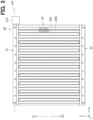
FIG. 3 is a back view illustrating a back structure of the heat exchanger of the first embodiment. -
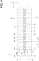
FIG. 4 is a top view illustrating a top structure of the heat exchanger of the first embodiment. -
FIG. 5 is a cross-sectional view illustrating a cross-sectional structure of a leeward first tank and a windward first tank of the heat exchanger of the first embodiment. -
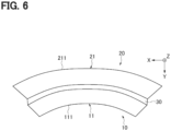
FIG. 6 is a top view schematically illustrating a deformation due to thermal strain of the top structure of the heat exchanger of the first embodiment. -
FIG. 7 is a top view illustrating a top structure of a heat exchanger of a second embodiment. -
FIG. 8 is a top view illustrating a top structure of a heat exchanger of a third embodiment. -
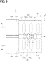
FIG. 9 is a top view illustrating a top structure of a heat exchanger of a fourth embodiment. -
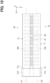
FIG. 10 is a top view illustrating a top structure of a heat exchanger of another embodiment. -
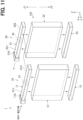
FIG. 11 is a diagram schematically illustrating a configuration of a heat exchanger according to another embodiment. -
FIG. 12 is a top view illustrating a top structure of a heat exchanger of another embodiment. -
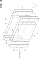
FIG. 13 is a diagram schematically illustrating a configuration of a heat exchanger according to another embodiment. -
FIG. 14 is a diagram schematically illustrating a configuration of a heat exchanger according to another embodiment. -
FIG. 15 is (A) a cross-sectional view illustrating a cross-sectional structure of a heat exchanger of another embodiment, and (B) a cross-sectional view illustrating a cross-sectional structure of a heat exchanger of another embodiment. - Hereinafter, an embodiment of a heat exchanger will be described with reference to the drawings. To facilitate understanding, identical constituent elements are assigned identical numerals in the drawings, and the duplicate descriptions will be omitted.
- First, a
heat exchanger 1 according to a first embodiment shown inFIG. 1 will be described. - The
heat exchanger 1 shown inFIG. 1 can be used, for example, as an indoor condenser which is one of components of a heat pump cycle of an air conditioner mounted on a vehicle. The air conditioner is a device that heats or cools an air flowing through an air conditioning duct and blows the air into a vehicle compartment, thereby heating or cooling the vehicle compartment. The heat pump cycle includes an expansion valve, an indoor evaporator, an outdoor heat exchanger, and a compressor in addition to the indoor condenser. Theheat exchanger 1 as the indoor condenser is arranged in the air conditioning duct, and performs heat exchange between a heat medium flowing through theheat exchanger 1 and the air flowing through the air conditioning duct. As a result, theheat exchanger 1 is used as a part that heats the air by absorbing heat from the heat medium into the air. - Next, a specific configuration of the
heat exchanger 1 will be described. - As shown in
FIG. 1 , theheat exchanger 1 includes a leeward heat-exchange portion 10 and a windward heat-exchange portion 20. Theheat exchanger 1 is made of a material such as an aluminum alloy. The leeward heat-exchange portion 10 and the windward heat-exchange portion 20 are arranged facing each other in an air flow direction Y The leeward heat-exchange portion 10 is arranged downstream in the air flow direction Y from the windward heat-exchange portion 20. In the present embodiment, the leeward heat-exchange portion 10 corresponds to a first heat-exchange portion, and the windward heat-exchange portion 20 corresponds to a second heat-exchange portion. - A Z-axis direction orthogonal to the air flow direction Y shown in
FIG. 1 is a vertical direction Z. Hereinafter, an upward direction in the vertical direction Z is referred to as an "upward vertical direction Z1", and a downward direction in the vertical direction Z is referred to as a "downward vertical direction Z2". Further, a direction orthogonal to both the air flow direction Y and the vertical direction Z is referred to as an X-axis direction. - The leeward heat-
exchange portion 10 includes a leewardfirst tank 11, aleeward core 12 and a leewardsecond tank 13. The leewardfirst tank 11, theleeward core 12, and the leewardsecond tank 13 are arranged in this order in the downward vertical direction Z2. - As shown in
FIG. 2 , theleeward core 12 has a stacking structure in whichtubes 120 andfins 121 are alternately arranged. In the present embodiment, theleeward core 12 corresponds to a first core. - Each
tube 120 is a member having a flat shape in a cross-section perpendicular to the vertical direction Z. Thetubes 120 are stacked with each other in the X-axis direction at predetermined intervals. Eachtube 120 extends in the vertical direction Z. An internal space of eachtube 120 constitutes a flow path through which the heat medium flows. Air flows through gaps defined between theadjacent ones tubes 120 in a direction indicated by an arrow Y - The
fins 121 are arranged in the gaps defined betweenadjacent ones tubes 120. Eachfin 121 is a so-called corrugated fin formed by bending a thin metal plate into a wavy shape. Peaks of a bent portion of thefin 121 are joined to an outer wall of atube 120 by brazing. Thefins 121 increase a heat transfer area exposed to air flowing outside thetubes 120. - The leeward
first tank 11 is provided at an upper end of theleeward core 12. The leewardfirst tank 11 has a cylindrical shape centered at an axis m1. The axis m1 is parallel to the X-axis direction. The leewardfirst tank 11 extends in the X-axis direction. The leewardfirst tank 11 is connected to an upper end of each of thetubes 120 of theleeward core 12. Aninflow portion 110 is attached to one end of the leewardfirst tank 11 in the X-axis direction. Theinflow portion 110 functions as a connector to which a pipe can be connected, and allows the heat medium supplied through the pipe to flow into the leewardfirst tank 11. In the present embodiment, the leewardfirst tank 11 corresponds to a first header tank. - The leeward
second tank 13 is provided at a lower end of theleeward core 12. The leewardsecond tank 13 has a cylindrical shape similar to the leewardfirst tank 11. The leewardsecond tank 13 is connected to a lower end of each of thetubes 120 of theleeward core 12. - As shown
FIG. 1 , the windward heat-exchange portion 20 includes a windwardfirst tank 21, awindward core 22 and a windwardsecond tank 23. The windwardfirst tank 21, thewindward core 22, and the windwardsecond tank 23 are arranged in this order in the downward vertical direction Z2. As shown inFIG. 3 , thewindward core 22 includestubes 220 andfins 221. In the present embodiment, thewindward core 22 corresponds to a second core. - Since a structure of each element constituting the windward heat-
exchange portion 20 is basically the same as a structure of a corresponding element of the leewardsecond tank 13, detailed descriptions thereof will be omitted. However, anoutflow portion 210, instead of theinflow portion 110, is attached to one end of the windwardfirst tank 21 in the X-axis direction. Theoutflow portion 210 functions as a connector to which a pipe can be connected, and allows the heat medium collected inside the windwardfirst tank 21 to flow out of the windwardfirst tank 21 through the pipe. In the present embodiment, the windwardfirst tank 21 corresponds to a second header tank. A reference sign m2 shown inFIG. 3 indicates a central axis of the windwardfirst tank 21. - An internal space of the leeward
second tank 13 and an internal space of the windwardsecond tank 23 communicate with each other directly or indirectly via a pipe, another tank, or the like. Therefore, the heat medium flowing through the internal space of the leewardsecond tank 13 is capable of flowing through the internal space of the windwardsecond tank 23. Thus, in theheat exchanger 1 of the present embodiment, the leeward heat-exchange portion 10 and the windward heat-exchange portion 20 are connected so that the heat medium is capable of flowing therebetween. - As shown in
FIG. 4 , the central axis m1 of the leewardfirst tank 11 and the central axis m2 of the windwardfirst tank 21 are parallel to each other. Hereinafter, the X-axis direction parallel to both of the central axes m1, m2 are referred to as a "tank longitudinal direction X". - As shown in
FIG. 4 , the leewardfirst tank 11 and the windwardfirst tank 21 are connected to each other via a connectingportion 30. More specifically, as shown inFIG. 5 , the leewardfirst tank 11 and the windwardfirst tank 21 are formed of afirst plate 41 and asecond plate 42. - The
first plate 41 has a flat shape, and is made of an aluminum alloy. Thefirst plate 41 has first insertion holes 411 and second insertion holes 412 spaced apart from the first insertion holes 411 in a Y-axis direction. The first insertion holes 411 and the second insertion holes 412 are passing through thefirst plate 41 in a thickness direction of thefirst plate 41. The first insertion holes 411 are arranged at predetermined intervals in the tank longitudinal direction X. The upper ends of thetubes 120 of theleeward core 12 are inserted into and joined to the first insertion holes 411. Similarly, the second insertion holes 412 are arranged at predetermined intervals in the tank longitudinal direction X. The upper ends of thetubes 220 of thewindward core 22 are inserted into and joined to the second insertion holes 412. - The
second plate 42 is made of a flat-shaped aluminum alloy. Thesecond plate 42 has been bent to have twopeaks peaks - The
first plate 41 is joined to a bottom surface of thesecond plate 42 by brazing. Thefirst plate 41 hasclaws 410. Theclaws 410 are crimped to hold both edges of thesecond plate 42 in the air flow direction. InFIG. 4 , theclaws 410 are omitted. - In the
heat exchanger 1 of the present embodiment, the leewardfirst tank 11 is formed of thefirst plate 41 and apeak 420 of thesecond plate 42 shown inFIG. 5 . The windwardfirst tank 21 is formed of thefirst plate 41 and apeak 421 of thesecond plate 42. The leewardfirst tank 11 and the windwardfirst tank 21 are connected to each other via a joint 30. The joint 30 is a part that joints thefirst plate 41 and thesecond plate 42, and is arranged between the leewardfirst tank 11 and the windwardfirst tank 21. In the present embodiment, the joint 30 corresponds to a connecting portion that connects the leewardfirst tank 11 and the windwardfirst tank 21, and therefore the joint 30 is hereinafter referred to as a "connectingportion 30". The leewardfirst tank 11, the windwardfirst tank 21, and the connectingportion 30 are provided upward of theleeward core 12 and thewindward core 22 in the upward vertical direction Z1. - As shown in
FIG. 4 , the connectingportion 30 hasslits 31. Each slit 31 is passing through the connectingportion 30 in the vertical direction Z. Each slit 31 is a rectangular through-hole, and a longitudinal direction of theslit 31 is parallel to the tank longitudinal direction X. Theslits 31 are arranged at a predetermined slit interval W1 in the tank longitudinal direction X. Each slit 31 is arranged at a position overlapping with thetubes 120 of theleeward core 12 and thetubes 220 of thewindward core 22 in the air flow direction Y A length W2 of each slit 31 in the tank longitudinal direction X is longer than the slit interval W1. - A
tank end surface 111 is defined as an end surface of the leewardfirst tank 11 opposite to a portion of the leewardfirst tank 11 connected to the connectingportion 30 in the air flow direction Y Thetubes 120 of theleeward core 12 is shifted from the connectingportion 30 toward thetank end surface 111 in the air flow direction Y A shortest distance H12 is defined as a shortest distance from thetank end surface 111 of the leewardfirst tank 11 to an outline of eachtube 120 in the air flow direction Y, and a shortest distance H11 is defined as a shortest distance from theslits 31 to the outline of thetube 120 in the air flow direction Y The shortest distance H12 is longer than the shortest distance H11. A shortest distance H22 is defined as a shortest distance from atank end surface 211 of the windwardfirst tank 21 to an outline of eachtube 220 in the air flow direction Y, and a shortest distance H21 is defined as a shortest distance from theslits 31 to the outline of thetube 220 in the air flow direction Y The shortest distance H22 is longer than the shortest distance H21. - Next, an exemplary operation of the
heat exchanger 1 of the present embodiment will be described. - In the
heat exchanger 1 of the present embodiment, the heat medium flows as indicated by arrows inFIG. 1 . That is, in theheat exchanger 1, when the heat medium flows into an internal space of the leewardfirst tank 11 from theinflow portion 110, the heat medium is distributed from the leewardfirst tank 11 to thetubes 120 of theleeward core 12. The heat medium flowing through each of thetubes 120 of theleeward core 12 is collected in the internal space of the leewardsecond tank 13 and then flows into the internal space of the windwardsecond tank 23. The heat medium that has flowed into the internal space of the windwardsecond tank 23 is distributed to thetubes 220 of thewindward core 22, and then, collected in the windwardfirst tank 21. The heat medium collected in the windwardfirst tank 21 flows out from theoutflow portion 210 to an outside. - In this
heat exchanger 1, a high-temperature gas-phase heat medium or a high-temperature two-phase heat medium in which a gas-phase heat medium and a liquid-phase heat medium are mixed flows into the leewardfirst tank 11 through theinflow portion 110. The high-temperature heat medium that has flowed into theinflow portion 110 exchanges heat with an air when flowing through thetubes 120 of theleeward core 12 and thetubes 220 of thewindward core 22, thereby releasing the heat to the air. As a result, the air is heated . On the other hand, the high-temperature gas-phase heat medium is cooled and transitions to a liquid-phase heat medium. Therefore, a proportion of the gas-phase heat medium to the liquid-phase heat medium increases in a downstream direction from the leewardfirst tank 11 toward the windwardfirst tank 21. Most of the heat medium flowing through an internal space of the windwardfirst tank 21 is in a low-temperature liquid phase. - Thus, in the
heat exchanger 1, the heat medium flowing through the leewardfirst tank 11 is largely different in temperature from the heat medium flowing through the windwardfirst tank 21, and the leewardfirst tank 11 and the windwardfirst tank 21 are connected to each other. In this structure, since thermal strains occur in thetanks tubes - In detail, the leeward
first tank 11, in which the high-temperature heat medium flows, is thermally deformed such that the leewardfirst tank 11 expands in the tank longitudinal direction X, while the windwardfirst tank 21, in which the low-temperature heat medium flows, is thermally deformed such that the windwardfirst tank 21 shrinks in the tank longitudinal direction X. Thereby, as shown inFIG. 6 , the leewardfirst tank 11 and the windwardfirst tank 21 are deformed into an arch shape. It has been confirmed by the inventors' simulation analysis that the deformation of thetanks tubes FIG. 4 . Thetubes - Contrary to this, as shown in
FIGS. 4 ,5 , in theheat exchanger 1 of the present embodiment, since theslits 31 are formed in the connectingportion 30, when thetanks slits 31 of the connectingportion 30 is capable of absorbing the difference in amount of deformation between thetanks slits 31 are provided in the connectingportion 30, deformations of thetanks tubes tubes tanks tubes tanks slits 31 in the connectingportion 30, and thetubes tanks tanks tubes tubes - According to the
heat exchanger 1 of the present embodiment described above, actions and effects described in the following items (1) to (5) can be obtained. - (1) Each slit 31 is formed in the connecting
portion 30 that connects the leewardfirst tank 11 and the windwardfirst tank 21 to each other. Theslit 31 is passing through the connectingportion 30. According to this configuration, theslit 31 is capable of absorbing a difference in amount of deformation between thetanks tubes - (2) As shown in
FIG. 4 , the length W2 of theslit 31 in the tank longitudinal direction X is longer than the slit interval W1 in the tank longitudinal direction X. According to this configuration, compared to a case where the length W2 of theslit 31 is shorter than the slit interval W1, theslit 31 is capable of absorbing more easily the difference in amount of deformation between thetanks tubes - (3) As shown in
FIG. 6 , when thetanks first tank 11, an amount of deformation at a position near thetank end surface 111 is greater than an amount of deformation at a position near the connectingportion 30. Similarly, in the windwardfirst tank 21 as well, an amount of deformation at a position near thetank end surface 211 is greater than an amount of deformation of at a position near the connectingportion 30. Regarding this, in theheat exchanger 1 of the present embodiment, as shown inFIG. 4 , the shortest distance H12 from thetank end surface 111 of the leewardfirst tank 11 to an outline of eachtube 120 in the air flow direction Y is longer than the shortest distance H11 from theslits 31 to the outline of thetube 120 in the air flow direction Y The shortest distance H22 from thetank end surface 111 of the windwardfirst tank 21 to an outline of eachtube 220 in the air flow direction Y is longer than the shortest distance H21 from theslits 31 to the outline of thetube 220 in the air flow direction Y According to this configuration, when thetanks tubes tubes - (4) Each slit 31 is arranged at a position overlapping with the
tubes 120 of theleeward core 12 and thetubes 220 of thewindward core 22 in the air flow direction Y According to this configuration, since theslits 31 are arranged near thetubes slits 31 can further reduce the stress concentration on thetubes - (5) The leeward
first tank 11 and the windwardfirst tank 21 are formed of thefirst plate 41 connected to thetubes 120 of theleeward core 12 and thetubes 220 of thewindward core 22, and thesecond plate 42 fixed to thefirst plate 41. Thefirst plate 41 and thesecond plate 42 define the internal space of the leewardfirst tank 11 and the internal space of the windwardfirst tank 21. Thefirst plate 41 and thesecond plate 42 form the connectingportion 30 between the internal space of the leewardfirst tank 11 and the internal space of the windwardfirst tank 21. According to this configuration, since the connectingportion 30 connects the leewardfirst tank 11 and windwardfirst tank 21, a connected structure can be easily realized. - Next, a
heat exchanger 1 of a second embodiment will be described. Hereinafter, differences from theheat exchanger 1 of the first embodiment will be mainly described. - As shown in
FIG. 7 , in theheat exchanger 1 of the present embodiment, anend slit 31a and acentral slit 31b have different lengths. More specifically, theend slit 31a is one ofslits 31 and is provided at an end of a connectingportion 30 in a tank longitudinal direction X. Thecentral slit 31b is one of theslits 31 and is provided between a center of the connectingportion 30 and the end slit 31a in the tank longitudinal direction X. A length of the end slit 31a in the tank longitudinal direction X is longer than a length of thecentral slit 31b in the tank longitudinal direction X. - According to the
heat exchanger 1 of the present embodiment described above, actions and effects described in the following item (6) can be further obtained.
(6) When thetanks tank 11 21 is greater than an amount of deformation at a center of thetank heat exchanger 1 of the present embodiment, the length of the end slit 31a in the tank longitudinal direction X is longer than the length of thecentral slit 31b in the tank longitudinal direction X. In other words, thelonger end slit 31a is arranged at a position where the amount of deformation is likely to increase at the time of thetanks end slit 31a is capable of absorbing a difference in the amount of deformation of thetanks tubes - Next, a
heat exchanger 1 of a third embodiment will be described. Hereinafter, differences from theheat exchanger 1 of the second embodiment will be mainly described. - As shown in
FIG. 8 , in theheat exchanger 1 of the present embodiment, widths ofopposite ends end slit 31a in the tank longitudinal direction X are different. More specifically, theslit 31 has oneend 310a and anotherend 310b that is opposite to the oneend 310a in the tank longitudinal direction X. The oneend 310a of theend slit 31a is located between an end of the connectingportion 30 and theother end 310b of theend slit 31a. Theother end 310b of the end slit 31a in the tank longitudinal direction X is located between a center of the connectingportion 30 and the oneend 310a of theend slit 31a. A width of the oneend 310a in the air flow direction Y is longer than a width of theother end 310b in the air flow direction Y - According to the
heat exchanger 1 of the present embodiment described above, actions and effects described in the following item (7) can be further obtained.
(7) When thetanks tanks 11 21 is greater than an amount of deformation at a center of thetanks heat exchanger 1 of the present embodiment, the width of the oneend 310a of theend slit 31a is longer than the width of theother end 310b of the end slit 31a In other words, the longer oneend 310a of theend slit 31a is arranged at a position where the amount of deformation is likely to increase at the time of thetanks end slit 31a is capable of absorbing a difference in amount of deformation between thetanks tubes - Next, a
heat exchanger 1 of a fourth embodiment will be described. Hereinafter, differences from theheat exchanger 1 of the first embodiment will be mainly described. - As shown in
FIG. 9 , in theheat exchanger 1 of the present embodiment, each slit 31 has an elliptical shape, and theslit 31 is arranged between twoadjacent tubes leeward core 12 in a tank longitudinal direction X. Atube 120a is one of the twoadjacent tubes end 11a of a leewardfirst tank 11 in the tank longitudinal direction X and another of the twoadjacent tubes tube 120b is the other of the twoadjacent tubes first tank 11 in the tank longitudinal direction X and the one of the twoadjacent tubes tube 120a and theslit 31 is longer than a shortest distance B12 between thetube 120b and theslit 31. - The
slit 31 is arranged between twoadjacent tubes windward core 22 in the tank longitudinal direction X. Atube 220a is one of the twoadjacent tubes end 21a of a windwardfirst tank 21 in the tank longitudinal direction X and another of the twoadjacent tubes tube 220b is the other of the twoadjacent tubes first tank 21 in the tank longitudinal direction X and the one of the twoadjacent tubes tube 220a and theslit 31 is longer than a shortest distance B22 between thetube 220b and theslit 31. - In the present embodiment, the
tube tube - According to the
heat exchanger 1 of the present embodiment described above, actions and effects described in the following item (8) can be further obtained. - (8) An inside of a
tube 120 near to the connectingportion 30 has a portion P11 and a portion P22 inside of thetube 120 as shown inFIG. 9 . An amount of deformation in the portion P11 is greater than an amount of deformation in the portion P12 when thetanks end 11a of the leewardfirst tank 11 and the portion P22 in the inside of thetube 120. The portion P12 is arranged between the center of the leewardfirst tank 11 and the portion P11 in the inside portion of thetube 120. In theheat exchanger 1 of the present embodiment, the shortest distance B11 between thetube 120a and theslit 31 is longer than the shortest distance B12 between thetube 120b and theslit 31. In other words, theslit 31 is arranged near to a portion of thetube 120 where the amount of deformation is more likely to increase. Therefore, the stress concentration in thetubes 120 can be further reduced. In addition, the similar operational effects can be obtained in thetubes 220. - The preceding embodiments may be practiced in the following embodiments.
- As shown in
FIG. 10 , theinflow portion 110 of the leewardfirst tank 11 and theoutflow portion 210 of the windwardfirst tank 21 may be integrally formed. In theheat exchanger 1, a temperature difference is the largest between theinflow portion 110 through which the high-temperature heat medium flows in and theoutflow portion 210 through which the low-temperature heat medium flows out. Therefore, when theinflow portion 110 and theoutflow portion 210 are arranged adjacent to each other, the thermal strain generated in them may be the largest. Regarding this, as shown inFIG. 10 , since theinflow portion 110 and theoutflow portion 210 are integrally formed, a rigidity thereof can be increased. As a result, deformations of theinflow portion 110 and theoutflow portion 210 due to the thermal strain can be reduced. As a result, deformations of thetanks tubes 120 can be further reduced. - In the
heat exchanger 1 of each embodiment, the flow of the heat medium may be changed as appropriate. For example, in aheat exchanger 1 shown inFIG. 11 , the leewardfirst tank 11 and the windwardfirst tank 21 may havepartition walls exchange portion 10 and the windward heat-exchange portion 20. In theheat exchanger 1, the high-temperature heat medium flows from theinflow portion 110 into one internal space S11 among two internal spaces S11, S12 partitioned by apartition wall 14 in the leewardfirst tank 11. Further, the low-temperature heat medium flows out from theoutflow portion 210 through one internal space S21 among two internal spaces S21, S22 partitioned by apartition wall 24 in the windwardfirst tank 21. In this configuration, the thermal strain is particularly likely to be generated between the internal space S11 of the leewardfirst tank 11 is and the internal space S21 of the windwardfirst tank 21. Therefore, as shown inFIG. 12 , aslit 31 may be provided only in a portion of the connectingportion 30 interposed between the internal space S11 of the leewardfirst tank 11 and the internal space S21 of the windwardfirst tank 21. - The structure of each
tank FIG. 5 , and can be appropriately changed. For example, the leewardfirst tank 11 and the windwardfirst tank 21 may be formed of different members, and the connectingportion 30 made of another member different from them may be joined to thetanks first tank 11 and the windwardfirst tank 21 may be directly joined by brazing, and then thecommunication portion 30 may be made of the brazed joint. In either structure, a heat exchanger in which thetanks portion 30 can be realized. - The
tubes 120 of theleeward core 12, thetubes 220 of thewindward core 22, or both thetubes 120 of theleeward core 12 and thetubes 220 of thewindward core 22 include a tube positioned without overlapping theslits 31 in the air flow direction Y - The structures of the leeward heat-
exchange portion 10 and the windward heat-exchange portion 20 of each embodiment can be appropriately changed. For example, as shown inFIGS. 13 and14 , the leeward heat-exchange portion 10 may havetanks leeward core 12 in the X-axis direction. Also, the windward heat-exchange portion 20 may havetanks windward core 22 in the X-axis direction. - As shown in
FIGS. 15(A) and 15(B) , thetubes 220 of thewindward core 22 and thetubes 120 of theleeward core 12 may be connected to each other viafins 40. Further, as shown inFIG. 15(A) , aslit 41 may be formed in thefins 40. According to this configuration, thefins 40 are capable of restraining expansion and shrink of thetubes tanks - The present disclosure is not limited to the specific examples described above. Those skilled in the art may appropriately modify the above described specific examples, and these modifications are also included in the scope of the present disclosure as long as they have the features of the present disclosure. Each element included in each of the specific examples described above, and the placement, condition, shape, and the like of the element are not limited to those illustrated, and can be modified as appropriate. The elements included in each of the specific examples described above can be appropriately combined as long as there is no technical contradiction.
Claims (15)
- A heat exchanger for heat exchange between heat medium flowing inside the heat exchanger and air flowing outside the heat exchanger, the heat exchanger comprisinga first heat-exchange portion (10) and a second heat-exchange portion (20) that are arranged facing each other in an air flow direction, and are connected to allow the heat medium to flow between the first heat-exchange portion and the second heat-exchange portion, whereinthe first heat-exchange portion includes a first core (12) having a stacked structure of tubes through which the heat medium flows, and a first header tank (11) connected to ends of the tubes of the first core and having an inflow portion (110) through which the heat medium flows into the first heat-exchange portion,the second heat-exchange portion includes a second core (22) having a stacked structure of tubes through which the heat medium flows, and a second header tank (21) connected to ends of the tubes of the second core and having an outflow portion (210) through which the heat medium flows out of the second heat-exchange portion,the first header tank allows a gas-phase heat medium to flow through the first header tank,the second header tank allows a liquid-phase heat medium to flow through the second header tank,the liquid-phase heat medium is lower in temperature than the gas-phase heat medium flowing through the first header tank,the first header tank and the second header tank are connected to each other via a connecting portion (30), andthe connecting portion has a slit (31) passing through the connecting portion.
- The heat exchanger according to claim 1, whereina tank longitudinal direction is defined as a direction parallel to both a central axis of the first header tank and a central axis of the second header tank,the slit is one of slits arranged side by side in the connecting portion at a predetermined slit interval in the tank longitudinal direction, anda length of each of the slits in the tank longitudinal direction is longer than a length of the slit interval in the tank longitudinal direction.
- The heat exchanger according to claim 1 or 2, whereinthe first header tank and the second header tank each have more than two parts connected by the connecting portion, andthe more than two parts are located at positions where an internal space of the first header tank through which the gas-phase heat medium flows and an internal space of the second header tank through which the liquid-phase heat medium flows overlap each other in the air flow direction.
- The heat exchanger according to any one of claims 1 to 3, further comprising a fin (40) connecting the first core and the second core.
- The heat exchanger according to any one of claims 1 to 4, whereina tank end surface is defined as an end surface of the first header tank opposite to a portion of the first header tank connected to the connecting portion in the air flow direction, anda shortest distance from the tank end surface to an outline of each tube of the first core in the air flow direction is longer than a shortest distance from the slit to the outline of the tube of the first core in the air flow direction.
- The heat exchanger according to any one of claims 1 to 5, wherein
the slit is arranged at a position overlapping in the air flow direction with the tubes of the first core and the tubes of the second core. - The heat exchanger according to claim 6, wherein
the tubes of the first core, the tubes of the second core, or both the tubes of the first core and the tubes of the second core include a tube positioned without overlapping the slit in the air flow direction. - The heat exchanger according to any one of claims 1 to 4, whereina tank end surface is defined as an end surface of the second header tank opposite to a portion of the second header tank connected to the connecting portion in the air flow direction, anda shortest distance from the tank end surface to an outline of each tube of the second core in the air flow direction is longer than a shortest distance from the slit to the outline of the tube of the second core in the air flow direction.
- The heat exchanger according to any one of claims 1 to 8, whereina tank longitudinal direction is defined as a direction parallel to both a central axis of the first header tank and a central axis of the second header tank,the slit has one end and another end that is opposite to the one end in the tank longitudinal direction,the one end of the slit is located between an end of the connecting portion and the other end of the slit,the other end of the slit is located between a center of the connecting portion and the one end of the slit, anda width of the one end of the slit in the air flow direction is longer than a width of the other end of the slit in the air flow direction.
- The heat exchanger according to any one of claims 1 to 8, whereina tank longitudinal direction is defined as a direction parallel to both a central axis of the first header tank and a central axis of the second header tank,the slit is one of slits arranged side by side in the connecting portion in the tank longitudinal direction,the slits include:an end slit (31a) provided at an end of the connecting portion in the tank longitudinal direction; anda central slit (31b) provided between a center of the connecting portion and the end slit in the tank longitudinal direction, anda length of the end slit in the tank longitudinal direction is longer than a length of the central slit in the tank longitudinal direction.
- The heat exchanger according to claim 1, whereina tank longitudinal direction is defined as a direction parallel to both a central axis of the first header tank and a central axis of the second header tank,the slit is one of slits arranged between two adjacent tubes of the first core in the tank longitudinal direction,one of the two adjacent tubes which is arranged between an end of the first header tank in the tank longitudinal direction and another of the two adjacent tubes is defined as a first tube (120a),the other of the two adjacent tubes which is arranged between a center of the first header tank in the longitudinal direction and the one of the two adjacent tubes is defined as a second tube (120b), anda shortest distance between the first tube and the slit is longer than a shortest distance between the second tube and the slit.
- The heat exchanger according to claim 1, whereina tank longitudinal direction is defined as a direction parallel to both a central axis of the first header tank and a central axis of the second header tank,the slit is one of slits arranged between two adjacent tubes of the second core in the tank longitudinal direction,one of the two adjacent tubes which is arranged between an end of the second header tank in the tank longitudinal direction and another of the two adjacent tubes is defined as a first tube (220a),the other of the two adjacent tubes which is arranged between a center of the second header tank in the longitudinal direction and the one of the two adjacent tubes is defined as a second tube (220b), anda shortest distance between the first tube and the slit is longer than a shortest distance between the second tube and the slit.
- The heat exchanger according to any one of claims 1 to 12, wherein
the first header tank, the second header tank, and the connecting portion are provided upward of the first core and the second core in a vertical direction. - The heat exchanger according to any one of claims 1 to 13, further comprisinga first plate (41) and a second plate (42) which form the first header tank and the second header tank, whereinthe first plate is connected to the tubes of the first core and the tubes of the second core,the second plate is fixed to the first plate,the first plate and the second plate define an internal space of the first header tank and an internal space of the second header tank, andthe first plate and the second plate form the connecting portion between the internal space of the first header tank and the internal space of the second header tank.
- The heat exchanger according to any one of claims 1 to 14, wherein
the inflow portion and the outflow portion are integrally formed.
Applications Claiming Priority (2)
| Application Number | Priority Date | Filing Date | Title |
|---|---|---|---|
| JP2020074064A JP2021169907A (en) | 2020-04-17 | 2020-04-17 | Heat exchanger |
| PCT/JP2021/014338 WO2021210428A1 (en) | 2020-04-17 | 2021-04-02 | Heat exchanger |
Publications (3)
| Publication Number | Publication Date |
|---|---|
| EP4137774A1 true EP4137774A1 (en) | 2023-02-22 |
| EP4137774A4 EP4137774A4 (en) | 2023-09-27 |
| EP4137774B1 EP4137774B1 (en) | 2024-07-03 |
Family
ID=78084940
Family Applications (1)
| Application Number | Title | Priority Date | Filing Date |
|---|---|---|---|
| EP21787545.9A Active EP4137774B1 (en) | 2020-04-17 | 2021-04-02 | Heat exchanger |
Country Status (5)
| Country | Link |
|---|---|
| US (1) | US12169103B2 (en) |
| EP (1) | EP4137774B1 (en) |
| JP (1) | JP2021169907A (en) |
| CN (1) | CN115413315B (en) |
| WO (1) | WO2021210428A1 (en) |
Families Citing this family (1)
| Publication number | Priority date | Publication date | Assignee | Title |
|---|---|---|---|---|
| CN117824149B (en) * | 2023-12-25 | 2024-06-07 | 山东三土能源股份有限公司 | Air source heat pump water heat exchanger |
Family Cites Families (9)
| Publication number | Priority date | Publication date | Assignee | Title |
|---|---|---|---|---|
| JP3674129B2 (en) * | 1996-02-07 | 2005-07-20 | 株式会社デンソー | Heterogeneous core integrated heat exchanger |
| DE19961199B4 (en) * | 1999-12-18 | 2007-10-04 | Modine Manufacturing Co., Racine | The heat exchanger |
| KR20050044325A (en) * | 2001-11-15 | 2005-05-12 | 쇼와 덴코 가부시키가이샤 | Heat exchanger, heat exchanger header tank and manufacturing method thereof |
| JP2005172357A (en) * | 2003-12-11 | 2005-06-30 | Calsonic Kansei Corp | Juxtaposed integrated heat exchanger |
| JP4931481B2 (en) * | 2006-06-06 | 2012-05-16 | 昭和電工株式会社 | Heat exchanger and manufacturing method thereof |
| JP2008020098A (en) * | 2006-07-11 | 2008-01-31 | Showa Denko Kk | Heat exchanger |
| JP2010169289A (en) * | 2009-01-21 | 2010-08-05 | Nikkei Nekko Kk | Bent heat exchanger and method of manufacturing the same |
| JP2013072607A (en) * | 2011-09-28 | 2013-04-22 | Keihin Thermal Technology Corp | Method of manufacturing heat exchanger |
| JP6711317B2 (en) * | 2017-06-13 | 2020-06-17 | 株式会社デンソー | Heat exchanger |
-
2020
- 2020-04-17 JP JP2020074064A patent/JP2021169907A/en active Pending
-
2021
- 2021-04-02 WO PCT/JP2021/014338 patent/WO2021210428A1/en not_active Ceased
- 2021-04-02 EP EP21787545.9A patent/EP4137774B1/en active Active
- 2021-04-02 CN CN202180028360.0A patent/CN115413315B/en active Active
-
2022
- 2022-10-13 US US17/965,095 patent/US12169103B2/en active Active
Also Published As
| Publication number | Publication date |
|---|---|
| US12169103B2 (en) | 2024-12-17 |
| CN115413315A (en) | 2022-11-29 |
| EP4137774A4 (en) | 2023-09-27 |
| WO2021210428A1 (en) | 2021-10-21 |
| JP2021169907A (en) | 2021-10-28 |
| EP4137774B1 (en) | 2024-07-03 |
| CN115413315B (en) | 2026-03-17 |
| US20230029816A1 (en) | 2023-02-02 |
Similar Documents
| Publication | Publication Date | Title |
|---|---|---|
| EP3060868B1 (en) | Heat exchanger and side plate | |
| US11493283B2 (en) | B-tube reform for improved thermal cycle performance | |
| EP3867587B1 (en) | Heat exchanger | |
| EP3194872B1 (en) | Multiport extruded heat exchanger | |
| JP3653909B2 (en) | Heat exchanger | |
| EP4137774B1 (en) | Heat exchanger | |
| WO2019111849A1 (en) | Heat exchanger | |
| JP5741470B2 (en) | Heat exchanger and method for manufacturing the same | |
| JP2004183960A (en) | Heat exchanger | |
| US10801781B2 (en) | Compliant b-tube for radiator applications | |
| JP2004069258A (en) | Flat tube, and method of manufacturing heat exchanger using flat tube | |
| JP2015121344A (en) | Heat exchanger | |
| US12546538B2 (en) | Microchannel heat exchanger tube supported bracket | |
| KR102158387B1 (en) | heat exchanger enhancing coherence of header tank | |
| KR100606332B1 (en) | Flat Tubes for Heat Exchangers in Air Conditioning Equipment | |
| KR20140015976A (en) | Tube for heat exchanger and manufacturing method of the same | |
| JPH06213534A (en) | Refrigerant condenser | |
| WO2022172638A1 (en) | Heat exchanger | |
| JP2004150643A (en) | Heat exchanger | |
| EP1726906A1 (en) | Heat exchanger |
Legal Events
| Date | Code | Title | Description |
|---|---|---|---|
| STAA | Information on the status of an ep patent application or granted ep patent |
Free format text: STATUS: THE INTERNATIONAL PUBLICATION HAS BEEN MADE |
|
| PUAI | Public reference made under article 153(3) epc to a published international application that has entered the european phase |
Free format text: ORIGINAL CODE: 0009012 |
|
| STAA | Information on the status of an ep patent application or granted ep patent |
Free format text: STATUS: REQUEST FOR EXAMINATION WAS MADE |
|
| 17P | Request for examination filed |
Effective date: 20221021 |
|
| AK | Designated contracting states |
Kind code of ref document: A1 Designated state(s): AL AT BE BG CH CY CZ DE DK EE ES FI FR GB GR HR HU IE IS IT LI LT LU LV MC MK MT NL NO PL PT RO RS SE SI SK SM TR |
|
| DAV | Request for validation of the european patent (deleted) | ||
| DAX | Request for extension of the european patent (deleted) | ||
| STAA | Information on the status of an ep patent application or granted ep patent |
Free format text: STATUS: EXAMINATION IS IN PROGRESS |
|
| A4 | Supplementary search report drawn up and despatched |
Effective date: 20230825 |
|
| RIC1 | Information provided on ipc code assigned before grant |
Ipc: F28D 1/04 20060101ALI20230821BHEP Ipc: F25B 39/04 20060101ALI20230821BHEP Ipc: F28F 9/02 20060101AFI20230821BHEP |
|
| 17Q | First examination report despatched |
Effective date: 20230906 |
|
| GRAP | Despatch of communication of intention to grant a patent |
Free format text: ORIGINAL CODE: EPIDOSNIGR1 |
|
| STAA | Information on the status of an ep patent application or granted ep patent |
Free format text: STATUS: GRANT OF PATENT IS INTENDED |
|
| RIC1 | Information provided on ipc code assigned before grant |
Ipc: F28D 1/04 20060101ALI20240118BHEP Ipc: F25B 39/04 20060101ALI20240118BHEP Ipc: F28F 9/02 20060101AFI20240118BHEP |
|
| INTG | Intention to grant announced |
Effective date: 20240208 |
|
| GRAS | Grant fee paid |
Free format text: ORIGINAL CODE: EPIDOSNIGR3 |
|
| GRAA | (expected) grant |
Free format text: ORIGINAL CODE: 0009210 |
|
| STAA | Information on the status of an ep patent application or granted ep patent |
Free format text: STATUS: THE PATENT HAS BEEN GRANTED |
|
| AK | Designated contracting states |
Kind code of ref document: B1 Designated state(s): AL AT BE BG CH CY CZ DE DK EE ES FI FR GB GR HR HU IE IS IT LI LT LU LV MC MK MT NL NO PL PT RO RS SE SI SK SM TR |
|
| REG | Reference to a national code |
Ref country code: CH Ref legal event code: EP |
|
| REG | Reference to a national code |
Ref country code: DE Ref legal event code: R096 Ref document number: 602021015274 Country of ref document: DE |
|
| REG | Reference to a national code |
Ref country code: LT Ref legal event code: MG9D |
|
| REG | Reference to a national code |
Ref country code: NL Ref legal event code: MP Effective date: 20240703 |
|
| PG25 | Lapsed in a contracting state [announced via postgrant information from national office to epo] |
Ref country code: PT Free format text: LAPSE BECAUSE OF FAILURE TO SUBMIT A TRANSLATION OF THE DESCRIPTION OR TO PAY THE FEE WITHIN THE PRESCRIBED TIME-LIMIT Effective date: 20241104 |
|
| REG | Reference to a national code |
Ref country code: AT Ref legal event code: MK05 Ref document number: 1700209 Country of ref document: AT Kind code of ref document: T Effective date: 20240703 |
|
| PG25 | Lapsed in a contracting state [announced via postgrant information from national office to epo] |
Ref country code: NL Free format text: LAPSE BECAUSE OF FAILURE TO SUBMIT A TRANSLATION OF THE DESCRIPTION OR TO PAY THE FEE WITHIN THE PRESCRIBED TIME-LIMIT Effective date: 20240703 |
|
| PG25 | Lapsed in a contracting state [announced via postgrant information from national office to epo] |
Ref country code: PT Free format text: LAPSE BECAUSE OF FAILURE TO SUBMIT A TRANSLATION OF THE DESCRIPTION OR TO PAY THE FEE WITHIN THE PRESCRIBED TIME-LIMIT Effective date: 20241104 Ref country code: NL Free format text: LAPSE BECAUSE OF FAILURE TO SUBMIT A TRANSLATION OF THE DESCRIPTION OR TO PAY THE FEE WITHIN THE PRESCRIBED TIME-LIMIT Effective date: 20240703 |
|
| PG25 | Lapsed in a contracting state [announced via postgrant information from national office to epo] |
Ref country code: NO Free format text: LAPSE BECAUSE OF FAILURE TO SUBMIT A TRANSLATION OF THE DESCRIPTION OR TO PAY THE FEE WITHIN THE PRESCRIBED TIME-LIMIT Effective date: 20241003 |
|
| PG25 | Lapsed in a contracting state [announced via postgrant information from national office to epo] |
Ref country code: FI Free format text: LAPSE BECAUSE OF FAILURE TO SUBMIT A TRANSLATION OF THE DESCRIPTION OR TO PAY THE FEE WITHIN THE PRESCRIBED TIME-LIMIT Effective date: 20240703 Ref country code: GR Free format text: LAPSE BECAUSE OF FAILURE TO SUBMIT A TRANSLATION OF THE DESCRIPTION OR TO PAY THE FEE WITHIN THE PRESCRIBED TIME-LIMIT Effective date: 20241004 Ref country code: PL Free format text: LAPSE BECAUSE OF FAILURE TO SUBMIT A TRANSLATION OF THE DESCRIPTION OR TO PAY THE FEE WITHIN THE PRESCRIBED TIME-LIMIT Effective date: 20240703 |
|
| PG25 | Lapsed in a contracting state [announced via postgrant information from national office to epo] |
Ref country code: BG Free format text: LAPSE BECAUSE OF FAILURE TO SUBMIT A TRANSLATION OF THE DESCRIPTION OR TO PAY THE FEE WITHIN THE PRESCRIBED TIME-LIMIT Effective date: 20240703 |
|
| PG25 | Lapsed in a contracting state [announced via postgrant information from national office to epo] |
Ref country code: LV Free format text: LAPSE BECAUSE OF FAILURE TO SUBMIT A TRANSLATION OF THE DESCRIPTION OR TO PAY THE FEE WITHIN THE PRESCRIBED TIME-LIMIT Effective date: 20240703 |
|
| PG25 | Lapsed in a contracting state [announced via postgrant information from national office to epo] |
Ref country code: AT Free format text: LAPSE BECAUSE OF FAILURE TO SUBMIT A TRANSLATION OF THE DESCRIPTION OR TO PAY THE FEE WITHIN THE PRESCRIBED TIME-LIMIT Effective date: 20240703 Ref country code: IS Free format text: LAPSE BECAUSE OF FAILURE TO SUBMIT A TRANSLATION OF THE DESCRIPTION OR TO PAY THE FEE WITHIN THE PRESCRIBED TIME-LIMIT Effective date: 20241103 |
|
| PG25 | Lapsed in a contracting state [announced via postgrant information from national office to epo] |
Ref country code: HR Free format text: LAPSE BECAUSE OF FAILURE TO SUBMIT A TRANSLATION OF THE DESCRIPTION OR TO PAY THE FEE WITHIN THE PRESCRIBED TIME-LIMIT Effective date: 20240703 Ref country code: CZ Free format text: LAPSE BECAUSE OF FAILURE TO SUBMIT A TRANSLATION OF THE DESCRIPTION OR TO PAY THE FEE WITHIN THE PRESCRIBED TIME-LIMIT Effective date: 20240703 |
|
| PG25 | Lapsed in a contracting state [announced via postgrant information from national office to epo] |
Ref country code: ES Free format text: LAPSE BECAUSE OF FAILURE TO SUBMIT A TRANSLATION OF THE DESCRIPTION OR TO PAY THE FEE WITHIN THE PRESCRIBED TIME-LIMIT Effective date: 20240703 Ref country code: RS Free format text: LAPSE BECAUSE OF FAILURE TO SUBMIT A TRANSLATION OF THE DESCRIPTION OR TO PAY THE FEE WITHIN THE PRESCRIBED TIME-LIMIT Effective date: 20241003 |
|
| PG25 | Lapsed in a contracting state [announced via postgrant information from national office to epo] |
Ref country code: RS Free format text: LAPSE BECAUSE OF FAILURE TO SUBMIT A TRANSLATION OF THE DESCRIPTION OR TO PAY THE FEE WITHIN THE PRESCRIBED TIME-LIMIT Effective date: 20241003 Ref country code: PL Free format text: LAPSE BECAUSE OF FAILURE TO SUBMIT A TRANSLATION OF THE DESCRIPTION OR TO PAY THE FEE WITHIN THE PRESCRIBED TIME-LIMIT Effective date: 20240703 Ref country code: NO Free format text: LAPSE BECAUSE OF FAILURE TO SUBMIT A TRANSLATION OF THE DESCRIPTION OR TO PAY THE FEE WITHIN THE PRESCRIBED TIME-LIMIT Effective date: 20241003 Ref country code: LV Free format text: LAPSE BECAUSE OF FAILURE TO SUBMIT A TRANSLATION OF THE DESCRIPTION OR TO PAY THE FEE WITHIN THE PRESCRIBED TIME-LIMIT Effective date: 20240703 Ref country code: IS Free format text: LAPSE BECAUSE OF FAILURE TO SUBMIT A TRANSLATION OF THE DESCRIPTION OR TO PAY THE FEE WITHIN THE PRESCRIBED TIME-LIMIT Effective date: 20241103 Ref country code: HR Free format text: LAPSE BECAUSE OF FAILURE TO SUBMIT A TRANSLATION OF THE DESCRIPTION OR TO PAY THE FEE WITHIN THE PRESCRIBED TIME-LIMIT Effective date: 20240703 Ref country code: GR Free format text: LAPSE BECAUSE OF FAILURE TO SUBMIT A TRANSLATION OF THE DESCRIPTION OR TO PAY THE FEE WITHIN THE PRESCRIBED TIME-LIMIT Effective date: 20241004 Ref country code: FI Free format text: LAPSE BECAUSE OF FAILURE TO SUBMIT A TRANSLATION OF THE DESCRIPTION OR TO PAY THE FEE WITHIN THE PRESCRIBED TIME-LIMIT Effective date: 20240703 Ref country code: ES Free format text: LAPSE BECAUSE OF FAILURE TO SUBMIT A TRANSLATION OF THE DESCRIPTION OR TO PAY THE FEE WITHIN THE PRESCRIBED TIME-LIMIT Effective date: 20240703 Ref country code: CZ Free format text: LAPSE BECAUSE OF FAILURE TO SUBMIT A TRANSLATION OF THE DESCRIPTION OR TO PAY THE FEE WITHIN THE PRESCRIBED TIME-LIMIT Effective date: 20240703 Ref country code: BG Free format text: LAPSE BECAUSE OF FAILURE TO SUBMIT A TRANSLATION OF THE DESCRIPTION OR TO PAY THE FEE WITHIN THE PRESCRIBED TIME-LIMIT Effective date: 20240703 Ref country code: AT Free format text: LAPSE BECAUSE OF FAILURE TO SUBMIT A TRANSLATION OF THE DESCRIPTION OR TO PAY THE FEE WITHIN THE PRESCRIBED TIME-LIMIT Effective date: 20240703 |
|
| REG | Reference to a national code |
Ref country code: DE Ref legal event code: R097 Ref document number: 602021015274 Country of ref document: DE |
|
| PG25 | Lapsed in a contracting state [announced via postgrant information from national office to epo] |
Ref country code: SM Free format text: LAPSE BECAUSE OF FAILURE TO SUBMIT A TRANSLATION OF THE DESCRIPTION OR TO PAY THE FEE WITHIN THE PRESCRIBED TIME-LIMIT Effective date: 20240703 Ref country code: DK Free format text: LAPSE BECAUSE OF FAILURE TO SUBMIT A TRANSLATION OF THE DESCRIPTION OR TO PAY THE FEE WITHIN THE PRESCRIBED TIME-LIMIT Effective date: 20240703 Ref country code: RO Free format text: LAPSE BECAUSE OF FAILURE TO SUBMIT A TRANSLATION OF THE DESCRIPTION OR TO PAY THE FEE WITHIN THE PRESCRIBED TIME-LIMIT Effective date: 20240703 |
|
| PG25 | Lapsed in a contracting state [announced via postgrant information from national office to epo] |
Ref country code: EE Free format text: LAPSE BECAUSE OF FAILURE TO SUBMIT A TRANSLATION OF THE DESCRIPTION OR TO PAY THE FEE WITHIN THE PRESCRIBED TIME-LIMIT Effective date: 20240703 |
|
| PG25 | Lapsed in a contracting state [announced via postgrant information from national office to epo] |
Ref country code: SK Free format text: LAPSE BECAUSE OF FAILURE TO SUBMIT A TRANSLATION OF THE DESCRIPTION OR TO PAY THE FEE WITHIN THE PRESCRIBED TIME-LIMIT Effective date: 20240703 |
|
| PLBE | No opposition filed within time limit |
Free format text: ORIGINAL CODE: 0009261 |
|
| STAA | Information on the status of an ep patent application or granted ep patent |
Free format text: STATUS: NO OPPOSITION FILED WITHIN TIME LIMIT |
|
| 26N | No opposition filed |
Effective date: 20250404 |
|
| PGFP | Annual fee paid to national office [announced via postgrant information from national office to epo] |
Ref country code: DE Payment date: 20250422 Year of fee payment: 5 |
|
| PGFP | Annual fee paid to national office [announced via postgrant information from national office to epo] |
Ref country code: IT Payment date: 20250424 Year of fee payment: 5 |
|
| PGFP | Annual fee paid to national office [announced via postgrant information from national office to epo] |
Ref country code: FR Payment date: 20250425 Year of fee payment: 5 |
|
| PG25 | Lapsed in a contracting state [announced via postgrant information from national office to epo] |
Ref country code: SE Free format text: LAPSE BECAUSE OF FAILURE TO SUBMIT A TRANSLATION OF THE DESCRIPTION OR TO PAY THE FEE WITHIN THE PRESCRIBED TIME-LIMIT Effective date: 20240703 |
|
| REG | Reference to a national code |
Ref country code: CH Ref legal event code: H13 Free format text: ST27 STATUS EVENT CODE: U-0-0-H10-H13 (AS PROVIDED BY THE NATIONAL OFFICE) Effective date: 20251125 |
|
| PG25 | Lapsed in a contracting state [announced via postgrant information from national office to epo] |
Ref country code: LU Free format text: LAPSE BECAUSE OF NON-PAYMENT OF DUE FEES Effective date: 20250402 |
|
| PG25 | Lapsed in a contracting state [announced via postgrant information from national office to epo] |
Ref country code: MC Free format text: LAPSE BECAUSE OF FAILURE TO SUBMIT A TRANSLATION OF THE DESCRIPTION OR TO PAY THE FEE WITHIN THE PRESCRIBED TIME-LIMIT Effective date: 20240703 |
|
| GBPC | Gb: european patent ceased through non-payment of renewal fee |
Effective date: 20250402 |
|
| REG | Reference to a national code |
Ref country code: BE Ref legal event code: MM Effective date: 20250430 |
|
| PG25 | Lapsed in a contracting state [announced via postgrant information from national office to epo] |
Ref country code: GB Free format text: LAPSE BECAUSE OF NON-PAYMENT OF DUE FEES Effective date: 20250402 |
|
| PG25 | Lapsed in a contracting state [announced via postgrant information from national office to epo] |
Ref country code: BE Free format text: LAPSE BECAUSE OF NON-PAYMENT OF DUE FEES Effective date: 20250430 |
|
| PG25 | Lapsed in a contracting state [announced via postgrant information from national office to epo] |
Ref country code: CH Free format text: LAPSE BECAUSE OF NON-PAYMENT OF DUE FEES Effective date: 20250430 |
|
| PG25 | Lapsed in a contracting state [announced via postgrant information from national office to epo] |
Ref country code: IE Free format text: LAPSE BECAUSE OF NON-PAYMENT OF DUE FEES Effective date: 20250402 |