JP6711317B2 - Heat exchanger - Google Patents
Heat exchanger Download PDFInfo
- Publication number
- JP6711317B2 JP6711317B2 JP2017116053A JP2017116053A JP6711317B2 JP 6711317 B2 JP6711317 B2 JP 6711317B2 JP 2017116053 A JP2017116053 A JP 2017116053A JP 2017116053 A JP2017116053 A JP 2017116053A JP 6711317 B2 JP6711317 B2 JP 6711317B2
- Authority
- JP
- Japan
- Prior art keywords
- tank
- windward
- heat exchange
- leeward
- claw
- Prior art date
- Legal status (The legal status is an assumption and is not a legal conclusion. Google has not performed a legal analysis and makes no representation as to the accuracy of the status listed.)
- Expired - Fee Related
Links
- 210000000078 claw Anatomy 0.000 claims description 111
- 239000012530 fluid Substances 0.000 claims description 33
- 238000006116 polymerization reaction Methods 0.000 claims description 6
- 239000003507 refrigerant Substances 0.000 description 95
- 238000004891 communication Methods 0.000 description 16
- 238000011144 upstream manufacturing Methods 0.000 description 16
- 238000005192 partition Methods 0.000 description 9
- 238000005057 refrigeration Methods 0.000 description 8
- 238000001816 cooling Methods 0.000 description 7
- 238000003780 insertion Methods 0.000 description 7
- 230000037431 insertion Effects 0.000 description 7
- 238000009826 distribution Methods 0.000 description 6
- 238000005304 joining Methods 0.000 description 6
- 238000005452 bending Methods 0.000 description 5
- 239000000463 material Substances 0.000 description 5
- 238000005219 brazing Methods 0.000 description 4
- 238000007689 inspection Methods 0.000 description 4
- 238000004378 air conditioning Methods 0.000 description 3
- 238000006073 displacement reaction Methods 0.000 description 3
- 238000012546 transfer Methods 0.000 description 3
- 229910000838 Al alloy Inorganic materials 0.000 description 2
- 238000013459 approach Methods 0.000 description 2
- 230000000052 comparative effect Effects 0.000 description 2
- 239000002826 coolant Substances 0.000 description 2
- 238000001514 detection method Methods 0.000 description 2
- 230000000694 effects Effects 0.000 description 2
- 239000010721 machine oil Substances 0.000 description 2
- 229910052751 metal Inorganic materials 0.000 description 2
- 239000002184 metal Substances 0.000 description 2
- 238000000034 method Methods 0.000 description 2
- 239000012808 vapor phase Substances 0.000 description 2
- 239000000498 cooling water Substances 0.000 description 1
- 238000010586 diagram Methods 0.000 description 1
- NBVXSUQYWXRMNV-UHFFFAOYSA-N fluoromethane Chemical compound FC NBVXSUQYWXRMNV-UHFFFAOYSA-N 0.000 description 1
- 238000010030 laminating Methods 0.000 description 1
- 238000003475 lamination Methods 0.000 description 1
- 230000001050 lubricating effect Effects 0.000 description 1
- 230000000379 polymerizing effect Effects 0.000 description 1
Images


Classifications
-
- F—MECHANICAL ENGINEERING; LIGHTING; HEATING; WEAPONS; BLASTING
- F28—HEAT EXCHANGE IN GENERAL
- F28D—HEAT-EXCHANGE APPARATUS, NOT PROVIDED FOR IN ANOTHER SUBCLASS, IN WHICH THE HEAT-EXCHANGE MEDIA DO NOT COME INTO DIRECT CONTACT
- F28D1/00—Heat-exchange apparatus having stationary conduit assemblies for one heat-exchange medium only, the media being in contact with different sides of the conduit wall, in which the other heat-exchange medium is a large body of fluid, e.g. domestic or motor car radiators
- F28D1/02—Heat-exchange apparatus having stationary conduit assemblies for one heat-exchange medium only, the media being in contact with different sides of the conduit wall, in which the other heat-exchange medium is a large body of fluid, e.g. domestic or motor car radiators with heat-exchange conduits immersed in the body of fluid
- F28D1/04—Heat-exchange apparatus having stationary conduit assemblies for one heat-exchange medium only, the media being in contact with different sides of the conduit wall, in which the other heat-exchange medium is a large body of fluid, e.g. domestic or motor car radiators with heat-exchange conduits immersed in the body of fluid with tubular conduits
- F28D1/053—Heat-exchange apparatus having stationary conduit assemblies for one heat-exchange medium only, the media being in contact with different sides of the conduit wall, in which the other heat-exchange medium is a large body of fluid, e.g. domestic or motor car radiators with heat-exchange conduits immersed in the body of fluid with tubular conduits the conduits being straight
- F28D1/0535—Heat-exchange apparatus having stationary conduit assemblies for one heat-exchange medium only, the media being in contact with different sides of the conduit wall, in which the other heat-exchange medium is a large body of fluid, e.g. domestic or motor car radiators with heat-exchange conduits immersed in the body of fluid with tubular conduits the conduits being straight the conduits having a non-circular cross-section
- F28D1/05366—Assemblies of conduits connected to common headers, e.g. core type radiators
- F28D1/05391—Assemblies of conduits connected to common headers, e.g. core type radiators with multiple rows of conduits or with multi-channel conduits combined with a particular flow pattern, e.g. multi-row multi-stage radiators
-
- F—MECHANICAL ENGINEERING; LIGHTING; HEATING; WEAPONS; BLASTING
- F28—HEAT EXCHANGE IN GENERAL
- F28D—HEAT-EXCHANGE APPARATUS, NOT PROVIDED FOR IN ANOTHER SUBCLASS, IN WHICH THE HEAT-EXCHANGE MEDIA DO NOT COME INTO DIRECT CONTACT
- F28D1/00—Heat-exchange apparatus having stationary conduit assemblies for one heat-exchange medium only, the media being in contact with different sides of the conduit wall, in which the other heat-exchange medium is a large body of fluid, e.g. domestic or motor car radiators
- F28D1/02—Heat-exchange apparatus having stationary conduit assemblies for one heat-exchange medium only, the media being in contact with different sides of the conduit wall, in which the other heat-exchange medium is a large body of fluid, e.g. domestic or motor car radiators with heat-exchange conduits immersed in the body of fluid
- F28D1/04—Heat-exchange apparatus having stationary conduit assemblies for one heat-exchange medium only, the media being in contact with different sides of the conduit wall, in which the other heat-exchange medium is a large body of fluid, e.g. domestic or motor car radiators with heat-exchange conduits immersed in the body of fluid with tubular conduits
- F28D1/0408—Multi-circuit heat exchangers, e.g. integrating different heat exchange sections in the same unit or heat exchangers for more than two fluids
- F28D1/0426—Multi-circuit heat exchangers, e.g. integrating different heat exchange sections in the same unit or heat exchangers for more than two fluids with units having particular arrangement relative to the large body of fluid, e.g. with interleaved units or with adjacent heat exchange units in common air flow or with units extending at an angle to each other or with units arranged around a central element
- F28D1/0435—Combination of units extending one behind the other
-
- F—MECHANICAL ENGINEERING; LIGHTING; HEATING; WEAPONS; BLASTING
- F28—HEAT EXCHANGE IN GENERAL
- F28F—DETAILS OF HEAT-EXCHANGE AND HEAT-TRANSFER APPARATUS, OF GENERAL APPLICATION
- F28F9/00—Casings; Header boxes; Auxiliary supports for elements; Auxiliary members within casings
- F28F9/02—Header boxes; End plates
- F28F9/0202—Header boxes having their inner space divided by partitions
- F28F9/0204—Header boxes having their inner space divided by partitions for elongated header box, e.g. with transversal and longitudinal partitions
- F28F9/0209—Header boxes having their inner space divided by partitions for elongated header box, e.g. with transversal and longitudinal partitions having only transversal partitions
- F28F9/0212—Header boxes having their inner space divided by partitions for elongated header box, e.g. with transversal and longitudinal partitions having only transversal partitions the partitions being separate elements attached to header boxes
-
- F—MECHANICAL ENGINEERING; LIGHTING; HEATING; WEAPONS; BLASTING
- F28—HEAT EXCHANGE IN GENERAL
- F28F—DETAILS OF HEAT-EXCHANGE AND HEAT-TRANSFER APPARATUS, OF GENERAL APPLICATION
- F28F9/00—Casings; Header boxes; Auxiliary supports for elements; Auxiliary members within casings
- F28F9/02—Header boxes; End plates
- F28F9/0219—Arrangements for sealing end plates into casing or header box; Header box sub-elements
- F28F9/0224—Header boxes formed by sealing end plates into covers
-
- B—PERFORMING OPERATIONS; TRANSPORTING
- B23—MACHINE TOOLS; METAL-WORKING NOT OTHERWISE PROVIDED FOR
- B23K—SOLDERING OR UNSOLDERING; WELDING; CLADDING OR PLATING BY SOLDERING OR WELDING; CUTTING BY APPLYING HEAT LOCALLY, e.g. FLAME CUTTING; WORKING BY LASER BEAM
- B23K1/00—Soldering, e.g. brazing, or unsoldering
- B23K1/0008—Soldering, e.g. brazing, or unsoldering specially adapted for particular articles or work
- B23K1/0012—Brazing heat exchangers
-
- B—PERFORMING OPERATIONS; TRANSPORTING
- B23—MACHINE TOOLS; METAL-WORKING NOT OTHERWISE PROVIDED FOR
- B23K—SOLDERING OR UNSOLDERING; WELDING; CLADDING OR PLATING BY SOLDERING OR WELDING; CUTTING BY APPLYING HEAT LOCALLY, e.g. FLAME CUTTING; WORKING BY LASER BEAM
- B23K2101/00—Articles made by soldering, welding or cutting
- B23K2101/04—Tubular or hollow articles
- B23K2101/14—Heat exchangers
-
- F—MECHANICAL ENGINEERING; LIGHTING; HEATING; WEAPONS; BLASTING
- F25—REFRIGERATION OR COOLING; COMBINED HEATING AND REFRIGERATION SYSTEMS; HEAT PUMP SYSTEMS; MANUFACTURE OR STORAGE OF ICE; LIQUEFACTION SOLIDIFICATION OF GASES
- F25B—REFRIGERATION MACHINES, PLANTS OR SYSTEMS; COMBINED HEATING AND REFRIGERATION SYSTEMS; HEAT PUMP SYSTEMS
- F25B39/00—Evaporators; Condensers
- F25B39/04—Condensers
-
- F—MECHANICAL ENGINEERING; LIGHTING; HEATING; WEAPONS; BLASTING
- F28—HEAT EXCHANGE IN GENERAL
- F28D—HEAT-EXCHANGE APPARATUS, NOT PROVIDED FOR IN ANOTHER SUBCLASS, IN WHICH THE HEAT-EXCHANGE MEDIA DO NOT COME INTO DIRECT CONTACT
- F28D21/00—Heat-exchange apparatus not covered by any of the groups F28D1/00 - F28D20/00
- F28D2021/0019—Other heat exchangers for particular applications; Heat exchange systems not otherwise provided for
- F28D2021/008—Other heat exchangers for particular applications; Heat exchange systems not otherwise provided for for vehicles
- F28D2021/0084—Condensers
-
- F—MECHANICAL ENGINEERING; LIGHTING; HEATING; WEAPONS; BLASTING
- F28—HEAT EXCHANGE IN GENERAL
- F28D—HEAT-EXCHANGE APPARATUS, NOT PROVIDED FOR IN ANOTHER SUBCLASS, IN WHICH THE HEAT-EXCHANGE MEDIA DO NOT COME INTO DIRECT CONTACT
- F28D21/00—Heat-exchange apparatus not covered by any of the groups F28D1/00 - F28D20/00
- F28D2021/0019—Other heat exchangers for particular applications; Heat exchange systems not otherwise provided for
- F28D2021/008—Other heat exchangers for particular applications; Heat exchange systems not otherwise provided for for vehicles
- F28D2021/0085—Evaporators
-
- F—MECHANICAL ENGINEERING; LIGHTING; HEATING; WEAPONS; BLASTING
- F28—HEAT EXCHANGE IN GENERAL
- F28F—DETAILS OF HEAT-EXCHANGE AND HEAT-TRANSFER APPARATUS, OF GENERAL APPLICATION
- F28F2275/00—Fastening; Joining
- F28F2275/04—Fastening; Joining by brazing
-
- F—MECHANICAL ENGINEERING; LIGHTING; HEATING; WEAPONS; BLASTING
- F28—HEAT EXCHANGE IN GENERAL
- F28F—DETAILS OF HEAT-EXCHANGE AND HEAT-TRANSFER APPARATUS, OF GENERAL APPLICATION
- F28F2275/00—Fastening; Joining
- F28F2275/08—Fastening; Joining by clamping or clipping
-
- F—MECHANICAL ENGINEERING; LIGHTING; HEATING; WEAPONS; BLASTING
- F28—HEAT EXCHANGE IN GENERAL
- F28F—DETAILS OF HEAT-EXCHANGE AND HEAT-TRANSFER APPARATUS, OF GENERAL APPLICATION
- F28F9/00—Casings; Header boxes; Auxiliary supports for elements; Auxiliary members within casings
- F28F9/02—Header boxes; End plates
- F28F9/04—Arrangements for sealing elements into header boxes or end plates
- F28F9/16—Arrangements for sealing elements into header boxes or end plates by permanent joints, e.g. by rolling
- F28F9/18—Arrangements for sealing elements into header boxes or end plates by permanent joints, e.g. by rolling by welding
Description
本発明は、熱交換器に関するものである。 The present invention relates to heat exchangers.
従来、複数のチューブを積層して構成されたコア部を、外部流体である空気の流れ方向に対して2つ直列に配置するとともに、各コア部におけるチューブの端部に、コア部毎に独立したヘッダタンクを設けた熱交換器が、特許文献1に開示されている。
Conventionally, two core portions, which are configured by stacking a plurality of tubes, are arranged in series in the flow direction of air that is an external fluid, and at the end portions of the tubes in each core portion, each core portion is independent.
この特許文献1の熱交換器では、各ヘッダタンクは、チューブの端部が挿入されるチューブ挿入穴が形成されたコアプレートと、コアプレートとともにタンク内空間を構成するタンク本体部とを備えている。コアプレートは、チューブ挿入穴が形成されたチューブ接合面と、チューブ接合面の両端部からコア部と反対側に向けて延びる2つの壁部を有している。そして、タンク本体部とコアプレートとの組み付け時に、コアプレートの2つの壁部の内面とタンク本体部の外面とを互いに接触させることで、タンク本体部とコアプレートとが位置決めされる。
In the heat exchanger of
さらに、特許文献1の熱交換器では、空気流れ上流側および下流側のコアプレートの対向面に突起部がそれぞれ設けられている。そして、両コアプレートの組み付け時に、両コアプレートの突起部の先端面を互いに接触させることで両コアプレートが位置決めされる。これにより、チューブを組み付け位置で保持することができる。
Further, in the heat exchanger of
しかしながら、上記特許文献1に記載の熱交換器では、両コアプレート間に突起部が設けられているため、熱交換器の大型化を招くおそれがある。
However, in the heat exchanger described in
本発明は上記点に鑑みて、外部流体の流れ方向に対して直列に配置された複数のコア部を備える熱交換器において、小型化を図ることを目的とする。 In view of the above points, the present invention has an object to reduce the size of a heat exchanger including a plurality of core portions arranged in series with respect to the flow direction of an external fluid.
上記目的を達成するため、請求項1に記載の発明では、第1流体と第2流体との間で熱交換を行う熱交換器において、第1流体の流れ方向に対して直列に配置された複数の熱交換部(17、18)を備え、複数の熱交換部は、それぞれ、第2流体が流れる複数のチューブ(171、181)を積層して構成されたコア部(17a、18a)と、複数のチューブの端部に接続されるとともに、複数のチューブに対して冷媒の分配または集合を行うヘッダタンク(31、32)と、を有しており、ヘッダタンクは、複数のチューブが挿入した状態で接合されるチューブ接合部(31a、32a)と、チューブ接合部とともにタンク内空間を構成するタンク本体部(31b、32b)と、を有しており、複数の熱交換部のチューブ接合部は、1つのコアプレート(40)により一体に構成されており、複数の熱交換部のうち少なくとも1つは、それぞれ、コア部側に向けて突出した爪部(31c、32c)を有しており、コアプレートには、爪部と嵌合する孔部(42)が設けられており、爪部が孔部に嵌合された状態で、タンク本体部がコアプレートに対して固定されており、第1流体の流れ方向に隣り合うタンク本体部のうち、一方のタンク本体部における他方のタンク本体部側の爪部と、他方のタンク本体部における一方のタンク本体部側の爪部とは、第1流体の流れ方向から見たときに非重合となる位置に配置されている。
In order to achieve the above object, in the invention according to
これによれば、タンク本体部(31b、32b)の爪部(31c、32c)がコアプレート(40)の孔部(42)に嵌合された状態で、タンク本体部(31b、32b)をコアプレート(40)に対して固定することで、タンク本体部(31b、32b)をコアプレート(40)の所望の位置に正確に位置決めすることができる。このとき、コアプレート(40)にタンク本体部(31b、32b)を位置決めする構造を別途設ける必要がないため、熱交換器(12)の小型化を図ることができる。
また、請求項2に記載の発明では、第1流体と第2流体との間で熱交換を行う熱交換器において、第1流体の流れ方向に対して直列に配置された複数の熱交換部(17、18)を備え、複数の熱交換部は、それぞれ、第2流体が流れる複数のチューブ(171、181)を積層して構成されたコア部(17a、18a)と、複数のチューブの端部に接続されるとともに、複数のチューブに対して第2流体の分配または集合を行うヘッダタンク(31、32)と、を有しており、ヘッダタンクは、複数のチューブが挿入した状態で接合されるチューブ接合部(31a、32a)と、チューブ接合部とともにタンク内空間を構成するタンク本体部(31b、32b)と、を有しており、複数の熱交換部のチューブ接合部は、1つのコアプレート(40)により一体に構成されており、複数の熱交換部のうち少なくとも1つは、タンク本体部からコア部側に向けて突出した爪部(31c、32c)を有しており、コアプレートには、爪部と嵌合する孔部(42)が設けられており、爪部が孔部に嵌合された状態で、タンク本体部がコアプレートに対して固定されており、コアプレートのうち、複数の熱交換部におけるチューブ接合部同士の間を、境界部(43)としたとき、孔部のうち、境界部に設けられる孔部は、爪部が接合される接合面(420)を有する接合部(42a)と、接合面を有しない非接合部(42b)とを備えており、非接合部は、接合部に対して、境界部における第1流体の流れ方向の中央側に配置されており、非接合部の接合部側の端部におけるチューブの積層方向の長さは、爪部の非接合部側の端部におけるチューブの積層方向の長さよりも短い。
According to this, with the claw portions (31c, 32c) of the tank body (31b, 32b) fitted in the hole (42) of the core plate (40), the tank body (31b, 32b) is removed. By fixing to the core plate (40), the tank main body (31b, 32b) can be accurately positioned at a desired position on the core plate (40). At this time, since it is not necessary to separately provide a structure for positioning the tank body portions (31b, 32b) on the core plate (40), the heat exchanger (12) can be downsized.
Further, in the invention according to claim 2, in the heat exchanger for exchanging heat between the first fluid and the second fluid, a plurality of heat exchange parts arranged in series with respect to the flow direction of the first fluid. (17, 18), each of the plurality of heat exchange sections includes a core section (17a, 18a) formed by stacking a plurality of tubes (171, 181) through which the second fluid flows, and a plurality of tubes. A header tank (31, 32) that is connected to the end and distributes or collects the second fluid to a plurality of tubes, and the header tank is in a state in which the plurality of tubes are inserted. It has a tube joint part (31a, 32a) to be joined and a tank main body part (31b, 32b) that constitutes a tank inner space together with the tube joint part, and the tube joint parts of the plurality of heat exchange parts are It is integrally configured by one core plate (40), and at least one of the plurality of heat exchange parts has a claw part (31c, 32c) protruding from the tank main body part toward the core part side. The core plate is provided with a hole (42) for fitting with the claw, and the tank body is fixed to the core plate with the claw fitted in the hole. When the boundary portions (43) are defined between the tube joint portions of the plurality of heat exchange portions of the core plate, the hole portions provided at the boundary portions of the hole portions are joint portions to which the claw portions are joined. A joint portion (42a) having a surface (420) and a non-joint portion (42b) having no joint surface are provided, and the non-joint portion has a flow direction of the first fluid at a boundary portion with respect to the joint portion. The length of the tube in the stacking direction at the end of the non-bonding part on the side of the bonding part is shorter than the length of the tube at the end of the claw part on the side of the non-bonding part in the stacking direction.
なお、この欄および特許請求の範囲で記載した各手段の括弧内の符号は、後述する実施形態に記載の具体的手段との対応関係を示すものである。 Note that the reference numerals in parentheses for each means described in this column and in the claims indicate the correspondence with the specific means described in the embodiments described later.
以下、本発明の実施形態について図に基づいて説明する。なお、以下の各実施形態相互において、互いに同一もしくは均等である部分には、図中、同一符号を付してある。 Embodiments of the present invention will be described below with reference to the drawings. In the following respective embodiments, the same or equivalent portions are designated by the same reference numerals in the drawings.
(第1実施形態)
図1に示す冷凍サイクル装置10は、車両用空調装置に適用されており、冷却対象空間である車室内へ送風される空気を冷却する機能を果たす。車室内へ送風される空気は、冷凍サイクル装置10の冷却対象流体である。
(First embodiment)
The
冷凍サイクル装置10では、冷媒としてフルオロカーボン系冷媒(具体的にはR1234yf)を採用しており、高圧側冷媒圧力が冷媒の臨界圧力を超えない亜臨界冷凍サイクルを構成している。さらに、冷媒には圧縮機11を潤滑するための冷凍機油が混入されている。冷凍機油の一部は冷媒とともにサイクルを循環している。
The
冷凍サイクル装置10の構成機器のうち、圧縮機11は、冷媒を吸入して高圧冷媒となるまで圧縮して吐出するものである。より具体的には、本実施形態の圧縮機11は、プーリ、ベルト等を介して車両走行用エンジンから伝達される回転駆動力によって駆動されるエンジン駆動式の圧縮機である。エンジン駆動式の圧縮機としては、吐出容量の変化により冷媒吐出能力を調整可能な可変容量型圧縮機、あるいは電磁クラッチの断続により圧縮機の稼働率を変化させて冷媒吐出能力を調整可能な固定容量型圧縮機を採用することができる。
Of the components of the
圧縮機11の吐出口には、放熱器12の冷媒入口側が接続されている。放熱器12は、圧縮機11から吐出された高圧側冷媒と冷却ファン13から送風された車室外空気(すなわち外気)を熱交換させることによって、高圧冷媒を放熱させて冷却する放熱用熱交換器である。
The refrigerant inlet side of the
放熱器12は、圧縮機11から吐出された高圧気相冷媒と冷却ファン13から送風された外気とを熱交換させ、高圧気相冷媒を放熱させて凝縮させる凝縮器である。なお、本実施形態の外気が本発明の第1流体に相当し、本実施形態の冷媒が本発明の第2流体に相当している。
The
冷却ファン13は、空調制御装置から出力される制御電圧によって回転数(すなわち送風空気量)が制御される電動送風機である。
The cooling
放熱器12の冷媒出口には、温度式膨張弁14の入口側が接続されている。温度式膨張弁14は、放熱器12から流出した冷媒を減圧させるとともに、サイクルを循環する冷媒の循環冷媒流量を調整する冷媒流量調整機構である。本実施形態の温度式膨張弁14は、蒸発器15出口側冷媒の過熱度が予め定めた基準過熱度に近づくように循環冷媒流量を調整する。
The refrigerant outlet of the
このような温度式膨張弁14としては、蒸発器15から流出した冷媒の温度と圧力とに応じて変位する変位部材(すなわちダイヤフラム)を有する感温部を備え、この変位部材の変位に応じて蒸発器15出口側冷媒の過熱度が基準過熱度に近づくように弁開度を調整する機械的機構を採用することができる。
Such a
温度式膨張弁14の出口には、蒸発器15が接続されている。蒸発器15は、送風ファン16から車室内へ向けて送風された空気と温度式膨張弁14から流出した低圧冷媒とを熱交換させ、低圧冷媒を蒸発させて吸熱作用を発揮させることによって空気を冷却する吸熱用熱交換器である。
An
送風ファン16は、空調制御装置から出力される制御電圧によって回転数(すなわち送風空気量)が制御される電動送風機である。蒸発器15の冷媒出口には、圧縮機11の吸入口側が接続されている。
The
蒸発器15および送風ファン16は、車両用空調装置の図示しない室内空調ユニットケース内に配置されている。
The
図2に示すように、放熱器12は、複数の熱交換部としての風上側放熱器17および風下側放熱器18を有している。風上側放熱器17および風下側放熱器18は、いわゆるタンクアンドチューブ型の熱交換器で構成されている。風上側放熱器17および風下側放熱器18の基本構成は互いに同等である。
As shown in FIG. 2, the
風上側放熱器17は、複数本の風上側チューブ171、風上側上部タンク172および風上側下部タンク173を有している。図2では、図示の都合上、風上側チューブ171、風上側上部タンク172および風上側下部タンク173については、風下側放熱器18の風下側チューブ181、風下側上部タンク182および風下側下部タンク183に括弧付きの符号を付して示している。
The
複数本の風上側チューブ171は、冷媒を流通させる管状部材である。風上側上部タンク172は、複数本の風上側チューブ171の一端部に接続されている。風上側上部タンク172は、複数本の風上側チューブ171に対して冷媒の分配および集合を行うヘッダタンクである。
The plurality of
風上側下部タンク173は、複数本の風上側チューブ171の他端部に接続されている。風上側下部タンク173は、複数本の風上側チューブ171に対して冷媒の分配および集合を行うヘッダタンクである。
The windward
風上側チューブ171は、伝熱性に優れる金属(例えばアルミニウム合金)で形成されている。風上側チューブ171は、その長手方向に垂直な断面形状が扁平形状に形成された扁平チューブで構成されている。
The
本実施形態の風上側チューブ171は、1枚の平板を折り曲げることにより形成されている。この平板は、伝熱性に優れる金属(例えばアルミニウム合金)で形成されている。また、風上側チューブ171の内部には、図16に示すようなインナーフィン190が設けられている。インナーフィン190は、風上側チューブ171と同じ材質の薄板材を波状に曲げ成形することによって形成されたコルゲートフィンである。インナーフィン190は、その頂部が風上側チューブ171の平坦面の内側にろう付け接合されている。
The
風上側放熱器17の各風上側チューブ171は、外表面の平坦面(すなわち扁平面)同士が互いに平行となるように、一定の間隔を開けて積層配置されている。これにより、隣り合う風上側チューブ171同士の間に、送風空気が流通する空気通路が形成される。つまり、風上側放熱器17では、複数本の風上側チューブ171が積層配置されることによって、冷媒と送風空気とを熱交換させる熱交換部が形成されている。
The
隣り合う風上側チューブ171同士の間に形成される空気通路には、フィン19が配置されている。フィン19は、冷媒と送風空気との熱交換を促進する熱交換促進部材である。
The
図3に示すように、フィン19は、風上側チューブ171と同じ材質の薄板材を波状に曲げ成形することによって形成されたコルゲートフィンである。フィン19は、その頂部が風上側チューブ171の平坦面の外側にろう付け接合されている。
As shown in FIG. 3, the
図2では、フィン19を風下側放熱器18の一部にのみ図示しているが、フィン19は、風上側放熱器17においては隣り合う風上側チューブ171間の略全域に渡って配置されている。さらに、フィン19は、風下側放熱器18においては隣り合う風下側チューブ181間の略全域に渡って配置されている。風上側チューブ171およびフィン19は、風上側コア部17aを構成している。
In FIG. 2, the
風上側放熱器17の風上側上部タンク172および風上側下部タンク173は、風上側チューブ171と同じ材質にて、筒状に形成されている。風上側上部タンク172および風上側下部タンク173は、風上側チューブ171の積層方向に延びる形状に形成されている。
The windward
風上側上部タンク172および風上側下部タンク173の内部には、各風上側チューブ171に対して冷媒を分配するための分配空間、および各風上側チューブ171から流出した冷媒を集合させるための集合空間が形成されている。
Inside the windward-side
風下側放熱器18は、風上側放熱器17と同様に、冷媒を流通させる複数本の風下側チューブ181、風下側上部タンク182および風下側下部タンク183を有している。
The
風下側チューブ181は、風上側チューブ171と同じ扁平チューブが採用されている。隣り合う風下側チューブ181同士の間に形成される空気通路には、フィン19が配置されている。
The
風下側チューブ181およびフィン19は、風下側コア部18aを構成している。風下側コア部18aは、風上側コア部17aを通過した空気と冷媒とを熱交換させる。
The
風下側上部タンク182は、複数本の風下側チューブ181に対して冷媒の分配を行うヘッダタンクである。風下側下部タンク183は、複数本の風下側チューブ181に対して冷媒の集合を行うヘッダタンクである。
The leeward side
図2および図4に示すように、放熱器12は第1ジョイント211および第2ジョイント212を有している。
As shown in FIGS. 2 and 4, the
第1ジョイント211は、冷媒流入口21aが設けられた接続用部材である。冷媒流入口21aは、圧縮機11の吐出口側に接続されている。第1ジョイント211は、風下側上部タンク182の一端側の側面にろう付け接合されている。第1ジョイント211の内部には、図示しない冷媒流入通路が形成されている。冷媒流入通路は、冷媒流入口21aから風下側上部タンク182の内部空間へ冷媒を導く冷媒通路である。
The first joint 211 is a connecting member provided with the
第2ジョイント212は、冷媒流出口21bが設けられた接続用部材である。冷媒流出口21bは、温度式膨張弁14の入口側に接続されている。第2ジョイント212は、風上側下部タンク173の一端側の側面にろう付け接合されている。第2ジョイント212の内部には、図示しない冷媒流出通路が形成されている。冷媒流出通路は、風上側下部タンク173から冷媒流出口21bへ冷媒を導く冷媒通路である。
The second joint 212 is a connecting member provided with the
図5および図6に示すように、風上側下部タンク173の内部には仕切部材174が配置されている。仕切部材174は、風上側下部タンク173の内部のうち、風上側チューブ171の積層方向における略中央部に配置されている。
As shown in FIGS. 5 and 6, a
仕切部材174は、風上側下部タンク173を、風上側チューブ171の積層方向(図5および図6では左右方向)に2つに仕切る仕切部である。仕切部材174により、風上側下部タンク173は、分配タンク部173aと集合タンク部173bとに仕切られている。
The
分配タンク部173aは、複数本の風上側チューブ171のうち風上側第1チューブ群171Aに冷媒を分配する。集合タンク部173bは、複数本の風上側チューブ171のうち風上側第2チューブ群171Bから冷媒を集合させる。集合タンク部173bの内部空間は、第2ジョイント212の冷媒流出口21bと連通している。
The
図6に示すように、風上側上部タンク172は、風上側第1チューブ群171Aで熱交換された冷媒を風上側第2チューブ群171Bに流入させる。
As shown in FIG. 6, the windward-side
図5、図6および図7に示すように、風上側下部タンク173と風下側下部タンク183との間には、内部に冷媒流路が形成された連通部材20が設けられている。連通部材20は、風上側下部タンク173の分配タンク部173aと風下側下部タンク183とを連通させる連通路である。
As shown in FIGS. 5, 6 and 7, a
風下側下部タンク183には、風下側連通孔183dが形成されている。風下側連通孔183dは、連通部材20の一端部と連通している。これにより、風下側下部タンク183内の冷媒は、風下側連通孔183dを介して連通部材20に流入する。
A
風上側下部タンク173には、風上側連通孔173dが形成されている。風上側連通孔173dは、連通部材20の他端部と連通している。これにより、連通部材20内の冷媒は、風上側連通孔173dを介して風上側下部タンク173に流入する。
A
風上側チューブ171、風上側上部タンク172、風上側下部タンク173、仕切部材174、風下側チューブ181、風下側上部タンク182、風下側下部タンク183、フィン19、連通部材20、第1ジョイント211および第2ジョイント212等をろう付け接合することによって、風上側放熱器17および風下側放熱器18が一体化されている。
ここで、放熱器12内に形成される冷媒流路を、図6を用いて説明する。第1ジョイント211の冷媒流入口21aから流入した冷媒は、図6の矢印R1に示すように、風下側上部タンク182へ流入する。
Here, the refrigerant channel formed in the
風下側上部タンク182の内部空間へ流入した冷媒は、矢印R2に示すように、風下側コア部18aの風下側チューブ181を上方側から下方側へ流れて風下側下部タンク183へ流入する。風下側下部タンク183へ流入した冷媒は、矢印R3に示すように、連通部材20を流れ、風上側下部タンク173の分配タンク部173aへ流入する。
The refrigerant flowing into the internal space of the leeward side
風上側下部タンク173の分配タンク部173aへ流入した冷媒は、矢印R4に示すように、風上側第1チューブ群171Aを下方側から上方側へ流れて風上側上部タンク172へ流入する。風上側上部タンク172へ流入した冷媒は、矢印R5に示すように、風上側上部タンク172の長手方向一端側から他端側へ流れ、風上側第2チューブ群171B
へ流入する。
The refrigerant flowing into the
Flow into.
風上側第2チューブ群171Bへ流入した冷媒は、矢印R6に示すように、風上側第2チューブ群171Bを上方側から下方側へ流れて風上側下部タンク173の集合タンク部173bへ流入する。集合タンク部173bへ流入した冷媒は、矢印R7に示すように、冷媒流出口21bから流出する。
The refrigerant that has flowed into the windward
続いて、本実施形態の風上側上部タンク172、風上側下部タンク173、風下側上部タンク182および風下側下部タンク183の詳細な構成について説明する。
Next, the detailed configurations of the windward-side
風上側上部タンク172および風上側下部タンク173は同様の構成であるため、以下の説明では、風上側上部タンク172および風上側下部タンク173をあわせて風上側タンク31と称する。また、風下側上部タンク182および風下側下部タンク183は同様の構成であるため、以下の説明では、風下側上部タンク182および風下側下部タンク183をあわせて風下側タンク32と称する。
Since the windward
図8に示すように、風上側タンク31は、複数の風上側チューブ171が挿入した状態で接合される風上側チューブ接合部31aと、風上側チューブ接合部31aとともにタンク内空間を構成する風上側タンク本体部31bと、を有している。風下側タンク32は、複数の風下側チューブ181が挿入した状態で接合される風下側チューブ接合部32aと、風下側チューブ接合部32aとともにタンク内空間を構成する風下側タンク本体部32bと、を有している。
As shown in FIG. 8, the
風上側チューブ接合部31aおよび風下側チューブ接合部32aは、1つのコアプレート40により一体に構成されている。すなわち、コアプレート40は、風上側チューブ接合部31aと、風下側チューブ接合部32aとを有している。
The windward side tube
風上側タンク本体部31bおよび風下側タンク本体部32bは、それぞれ、チューブ171、181の積層方向から見た断面が略U字状に形成されている。
The leeward side tank
図8および図9に示すように、風上側タンク本体部31bは、コアプレート40側(すなわち風上側コア部17a側)に向けて突出した風上側爪部31cを有している。風下側タンク本体部32bは、コアプレート40側(すなわち風下側コア部18a側)に向けて突出した風下側爪部32cを有している。
As shown in FIGS. 8 and 9, the windward side tank
なお、図9および後述する図10では、図示の都合上、風下側タンク本体部32bの風下側爪部32c等の構成部品については、風上側タンク本体部31bの風上側爪部31c等の構成部品に括弧付きの符号を付して示している。
Note that, in FIG. 9 and FIG. 10 described later, for convenience of illustration, components such as the leeward
ここで、風上側タンク本体部31bおよび風下側タンク本体部32bにおけるコアプレート40側の端面、すなわちコアプレート40と接触する端面を、先端面31d、31e、32e、32dという。また、先端面31d、31e、32e、32dのうち、チューブ171、181に対して空気流れ上流側の先端面を上流側先端面31d、32dといい、チューブ171、181に対して空気流れ下流側の面を下流側先端面31e、32eという。
Here, the end faces of the windward tank
続いて、本実施形態における爪部(すなわち風上側爪部31cおよび風下側爪部32c)の詳細な構成について説明する。なお、風下側爪部32cは風上側爪部31cと同様の構成であるため、風下側爪部32c等に関する説明は省略する。
Subsequently, a detailed configuration of the claw portions (that is, the windward
風上側爪部31cは、風上側タンク本体部31bの上流側先端面31dおよび下流側先端面31eにそれぞれ複数設けられている。上流側先端面31dおよび下流側先端面31eにおいて、複数の風上側爪部31cは、互いに間隔を空けて配置されている。
A plurality of windward
また、風上側タンク本体部31bにおいて、上流側先端面31dに形成される風上側爪部31cと、下流側先端面31eに形成される風上側爪部31cとは、空気流れ方向A1から見たときに非重合となる位置に配置されている。つまり、上流側先端面31dに形成される風上側爪部31cと、下流側先端面31eに形成される風上側爪部31cとは、空気流れ方向A1から見たときにずれて配置されている。
Further, in the windward
図10に示すように、風上側爪部31cにおけるコアプレート40側の先端部には、コアプレート40と反対側に向けて窪んだ溝部31fが形成されている。溝部31fは、風上側爪部31cにおけるコアプレート40側の先端部のうち、風上側チューブ171の積層方向の中央部に設けられている。この溝部31fにより、風上側爪部31cにおけるコアプレート40側の先端部は、2つの先端爪部31gに分割されている。
As shown in FIG. 10, a
本実施形態の先端爪部31gは、それぞれ、側面にテーパ面を有する四角錐台形状に形成されている。すなわち、本実施形態の先端爪部31gは、それぞれ、先端面31d、31e側からコアプレート40側に向けて先細りとなる四角錐台形状に形成されている。
The
なお、風上側爪部31cにおける先端爪部31gを除く部位(以下、根本部という)の外形は、長方形状に形成されている。すなわち、風上側爪部31cの根本部は、風上側チューブ171の長手方向から見た断面が長方形状に形成されている。
In addition, the outer shape of a portion (hereinafter, referred to as a root portion) of the windward
図11に示すように、風上側タンク本体部31bにおける下流側先端面31eに設けられた風上側爪部31cと、風下側タンク本体部32bにおける上流側先端面32dに設けられた風下側爪部32cとは、空気流れ方向A1から見た時に非重合となる位置に配置されている。つまり、風上側タンク本体部31bにおける風下側タンク本体部32b側の風上側爪部31cと、風下側タンク本体部32bにおける風上側タンク本体部31b側の風下側爪部32cとは、空気流れ方向A1から見た時に非重合となる位置に配置されている。すなわち、空気流れ方向A1に隣り合うタンク本体部31b、32bのうち、一方のタンク本体部31bにおける他方のタンク本体部32b側の爪部31cと、他方のタンク本体部32bにおける一方のタンク本体部31b側の爪部32cとは、空気流れ方向A1から見たときに非重合となる位置に配置されている。
As shown in FIG. 11, the windward
図12に示すように、コアプレート40において、風下側チューブ接合部32aと、風上側チューブ接合部31aとは、空気流れ方向A1に直列に配置されている。風下側チューブ接合部32aおよび風上側チューブ接合部31aには、それぞれ、チューブ171、181の長手方向端部が挿入されるチューブ挿入穴41が複数形成されている。
As shown in FIG. 12, in the
コアプレート40には、風上側爪部31cおよび風下側爪部32cのそれぞれと嵌合する孔部42が設けられている。そして、風上側爪部31cおよび風下側爪部32cのそれぞれが孔部42に嵌合された状態で、風上側タンク本体部31bおよび風下側タンク本体部32bがコアプレート40に対して固定されている。
The
より詳細には、風上側爪部31cおよび風下側爪部32cを孔部42に嵌合した後、風上側爪部31cおよび風下側爪部32cをコア部17a、18a側から割ることにより、風上側爪部31cおよび風下側爪部32cはコアプレート40に対してかしめ固定されている。これによれば、タンク本体部31b、32bとコアプレート40との密着性を増加させて、タンク本体部31b、32bとコアプレート40との間の未ろう付けを抑制できる。
More specifically, after the windward
ところで、孔部42は、コアプレート40において、風上側チューブ接合部31aよりも空気流れ上流側の部位、風下側チューブ接合部32aよりも空気流れ下流側の部位、および風上側チューブ接合部31aと風下側チューブ接合部32aとの間の部位に配置されている。以下、コアプレート40における風上側チューブ接合部31aと風下側チューブ接合部32aとの間の部位を、境界部43という。
By the way, in the
境界部43には、コアプレート40の表裏を貫通するスリット44が形成されている。スリット44は、境界部43における孔部42を除く部位に複数設けられている。スリット44は、チューブ171、181の積層方向に延びるように形成されている。
A
図12および図13に示すように、境界部43に設けられる孔部42は、接合部42aおよび非接合部42bを有している。
As shown in FIGS. 12 and 13, the
接合部42aは、爪部31c、32cが接合される接合面420を有している。具体的には、接合部42aは、爪部31c、32cの根本部の外形に応じた長方形状に形成されている。接合部42aの長方形状のうち、後述する3辺に爪部31c、32cが接合されている。すなわち、接合部42aの長方形状のうち、3辺が接合面420を形成している。
The
ここで、上述した3辺とは、接合部42aの長方形状において、空気流れ方向A1に延びる2つの辺と、チューブ171、181の積層方向に延びる2辺のうち境界部43における空気流れ方向A1の外側の1辺ある。したがって、接合部42aの長方形状において、チューブ171、181の積層方向に延びる2辺のうち境界部43における空気流れ方向A1の内側の1辺には、爪部31c、32cは接合されていない。
Here, the above-mentioned three sides are, in the rectangular shape of the
非接合部42bは、接合面420を有していない。すなわち、非接合部42bには、爪部31c、32cが接合されていない。
The
非接合部42bは、接合部42aに対して、境界部43における空気流れ方向A1の内側に配置されている。つまり、非接合部42bは、接合部42aに対して、境界部43における空気流れ方向A1の中央側に配置されている。換言すると、非接合部42bは、接合部42aに対して、コアプレート40における空気流れ方向A1の中央側(すなわち内側)に配置されている。
The
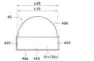
非接合部42bは、接合部42aから遠ざかるにつれて、チューブ171、181の積層方向の長さが短くなるような形状に形成されている。本実施形態では、非接合部42bは、半円状に形成されている。
The
また、非接合部42bの接合部42a側の端部におけるチューブ171、181の積層方向の長さL10は、爪部31c、32cの非接合部42b側の端部におけるチューブ171、181の積層方向の長さL20よりも短い。これにより、爪部31c、32cを孔部42に挿入した際に、爪部31c、32cが接合部42aから非接合部42b側にずれることを抑制している。
The length L10 in the stacking direction of the
ここで、図14に示すように、コアプレート40において、孔部42とスリット44との間の最短距離をL1、L2といい、孔部42とチューブ挿入穴41との間の最短距離をL3という。本実施形態では、孔部42、スリット44およびチューブ挿入穴41は、L1<L3かつL2<L3の関係を満たすように配置されている。
Here, as shown in FIG. 14, in the
以上説明したように、本実施形態では、タンク本体部31b、32bの爪部31c、32cをコアプレート40の孔部42に嵌合させることにより、タンク本体部31b、32bをコアプレート40に対して固定している。これにより、タンク本体部31b、32bをコアプレート40の所望の位置に正確に位置決めすることができる。このとき、コアプレート40にタンク本体部31b、32bを位置決めするための構造を別途設ける必要がないため、放熱器12の小型化を図ることができる。
As described above, in the present embodiment, the
ここで、比較例として、図15に示すように、本実施形態の放熱器12に対して、爪部31c、32cおよび孔部42が設けられていない構成が考えられる。このような構成では、タンク本体部31b、32bをコアプレート40に対して位置決めするために、コアプレート40の境界部43に、コア部17a、18aと反対側に向けて突出した凸部49が設けられている。このため、凸部49の空気流れ方向A1の長さ分だけ、放熱器が大型化してしまう。
Here, as a comparative example, as shown in FIG. 15, a configuration in which the
これに対し、本実施形態では、上述したように、爪部31c、32cを孔部42に嵌合させた状態で、タンク本体部31b、32bをコアプレート40に対して固定しているので、凸部49を廃止することができる。このため、放熱器12を小型化することが可能となる。
On the other hand, in the present embodiment, as described above, since the
また、本実施形態では、風上側チューブ接合部31aおよび風下側チューブ接合部32aを1つのコアプレート40により一体に構成している。このため、放熱器12の組み付け時に、風上側チューブ171および風下側チューブ181の全てを所定の間隔で配置した後、コアプレート40をこれらのチューブ171、181に容易に組み付けることができる。
Further, in the present embodiment, the windward side tube
また、本実施形態では、風上側タンク本体部31bと風下側タンク本体部32bとを別体として構成している。これにより、風上側タンク31と風下側タンク32との間の熱移動を抑制できる。このため、風上側タンク31内の冷媒および風下側タンク32内の冷媒のうち、一方の高温冷媒の熱により他方の低温冷媒が加熱されるという熱害が発生することを抑制できる。
Further, in this embodiment, the leeward tank
また、本実施形態では、風上側タンク本体部31bにおける下流側先端面31eに設けられた風上側爪部31cと、風下側タンク本体部32bにおける上流側先端面32dに設けられた風下側爪部32cとを、空気流れ方向A1から見た時に非重合となる位置に配置している。これによれば、コアプレート40における境界部43の空気流れ方向A1の長さを短くすることができる。このため、放熱器12をより小型化することが可能となる。
In addition, in the present embodiment, the windward
また、本実施形態では、コアプレート40の境界部43にスリット44を設けている。これによれば、風上側タンク31と風下側タンク32との間の熱移動を抑制できるので、上述した熱害が発生することを抑制できる。
Further, in this embodiment, the
また、本実施形態では、境界部43に設けられる孔部42に、接合部42aおよび非接合部42bを設けている。これによれば、接合部42aにおいて、孔部42と爪部31c、32cとを接合することができるので、風上側タンク31および風下側タンク32のシール性を確保できる。さらに、非接合部42bを設けることで、境界部43の板面積を低減できる。これにより、風上側タンク31と風下側タンク32との間の熱移動を抑制できるので、上述した熱害が発生することをより抑制できる。
Further, in the present embodiment, the
また、本実施形態では、爪部31c、32cにおけるコアプレート40側の先端部に溝部31f、32fを設けている。これによれば、風上側爪部31cおよび風下側爪部32cをコアプレート40に対してかしめ固定する際に、風上側爪部31cおよび風下側爪部32cを割りやすくすることができる。
Further, in the present embodiment, the
また、本実施形態では、爪部31c、32cの先端爪部31g、32gを四角錐台形状に形成している。これによれば、爪部31c、32cの孔部42に対する挿入性を良好にできる。
In addition, in the present embodiment, the
また、本実施形態では、図14に示すように、孔部42、スリット44およびチューブ挿入穴41は、L1<L3かつL2<L3の関係を満たすように配置されている。これによれば、爪部31c、32cをコアプレート40にかしめ固定した際に、L1部(すなわち、孔部42とスリット44との間が最短距離となる部分)が優先的に変形することで、チューブ挿入穴41が変形することを抑制できる。このため、ろう付け性を向上させることができる。
Further, in the present embodiment, as shown in FIG. 14, the
ところで、本実施形態のチューブ171、181は、1枚の平板を折り曲げることにより形成されている。このように形成されたチューブ171、181の接合検査方法として、図16に示すように、チューブ171、181、インナーフィン190およびコアプレート40等を一体ろう付けにより接合した後、チューブ171、181の未ろう付け部を膨らませ、膨らんだ部位を視覚的に検査する方法がある。
By the way, the
このような検査を行う際に、風上側チューブ接合部31aおよび風下側チューブ接合部32aが異なる部材により構成されている場合、風上側チューブ171と風下側チューブ181との間で位置ずれが生じ、未ろう付け部の誤検出が起こるおそれがある。
When performing such an inspection, when the windward-side tube
これに対し、本実施形態では、風上側チューブ接合部31aおよび風下側チューブ接合部32aが1つのコアプレート40により一体に構成されているので、風上側チューブ171および風下側チューブ181の位置ずれを抑制できる。これにより、チューブ171、181の接合検査において、未ろう付け部の誤検出を抑制できる。
On the other hand, in the present embodiment, since the windward side tube
(第2実施形態)
次に、本発明の第2実施形態について図17に基づいて説明する。本実施形態は、上記第1実施形態と比較して、風上側タンク31および風下側タンク32の構成が異なるものである。
(Second embodiment)
Next, a second embodiment of the present invention will be described based on FIG. The present embodiment is different from the first embodiment in the configurations of the
図17に示すように、風上側タンク本体部31bの風上側爪部31cは、上流側先端面31dおよび下流側先端面31eのうち、下流側先端面31eに設けられている。すなわち、風上側爪部31cは、風上側タンク本体部31bの上流側先端面31dには設けられていない。
As shown in FIG. 17, the windward
同様に、風下側タンク本体部32bの風下側爪部32cは、上流側先端面32dおよび下流側先端面32eのうち、下流側先端面32eに設けられている。すなわち、風下側爪部32cは、風下側タンク本体部32bの上流側先端面32dには設けられていない。
Similarly, the leeward
本実施形態によれば、コアプレート40の境界部43に、風下側爪部32cが嵌合する孔部42を設ける必要はなく、風上側爪部31cが嵌合する孔部42を設けるだけでよい。このため、境界部43の空気流れ方向A1の長さを短くすることができるので、放熱器12を確実に小型化することができる。
According to the present embodiment, the
(第3実施形態)
次に、本発明の第3実施形態について図18に基づいて説明する。本実施形態は、上記第1実施形態と比較して、風上側タンク31および風下側タンク32の構成が異なるものである。
(Third Embodiment)
Next, a third embodiment of the present invention will be described based on FIG. The present embodiment is different from the first embodiment in the configurations of the
図18に示すように、風上側タンク31および風下側タンク32は、1枚の板状部材である1つのコアプレート40により一体に形成されている。すなわち、風上側チューブ接合部31a、風上側タンク本体部31b、風下側チューブ接合部32aおよび風下側タンク本体部32bは、1つのコアプレート40により一体に構成されている。
As shown in FIG. 18, the
具体的には、コアプレート40における空気流れ方向A1の上流側端部45には、風上側爪部31cが形成されている。コアプレート40における空気流れ方向A1の下流側端部46には、風下側爪部32cが形成されている。コアプレート40における空気流れ方向A1の略中央側(すなわち境界部43)には、風上側爪部31cまたは風下側爪部32cと嵌合する孔部42が形成されている。
Specifically, the
そして、コアプレート40が空気流れ方向A1の両端部45、46から内側に向けて折り曲げられて、風上側爪部31cおよび風下側爪部32cが孔部42に嵌合されることにより、風上側タンク31および風下側タンク32が形成されている。このとき、本実施形態では、風上側チューブ接合部31aおよび風下側チューブ接合部32aは、略平板状に形成されている。また、風上側タンク本体部31bおよび風下側タンク本体部32bは、チューブ171、181の積層方向から見た断面がコア部17a、18aと反対側に向けて突出する円弧状に形成されている。
Then, the
その他の放熱器12の構成は、第1実施形態と同様である。本実施形態によれば、板状部材であるコアプレート40の両端部の爪部31c、32cが孔部42に嵌合されるように1つのコアプレート40を折り曲げることで、風上側タンク31および風下側タンク32を形成することができる。このとき、風上側タンク31および風下側タンク32を位置決めする構造を別途設ける必要がないため、放熱器12の小型化を図ることができる。
Other configurations of the
さらに、本実施形態では、風上側チューブ接合部31a、風上側タンク本体部31b、風下側チューブ接合部32aおよび風下側タンク本体部32bを、1つの部品であるコアプレート40により形成しているので、部品点数を削減することが可能となる。
Further, in the present embodiment, the windward side tube
(第4実施形態)
次に、本発明の第4実施形態について図19に基づいて説明する。本実施形態は、上記第3実施形態と比較して、風上側タンク31および風下側タンク32の構成が異なるものである。
(Fourth Embodiment)
Next, a fourth embodiment of the present invention will be described based on FIG. The present embodiment is different from the third embodiment in the configurations of the
図19に示すように、本実施形態では、風上側チューブ接合部31aおよび風下側チューブ接合部32aは、チューブ171、181の積層方向から見た断面がコア部17a、18a側に向けて突出する円弧状に形成されている。また、風上側タンク本体部31bおよび風下側タンク本体部32bは、略平板状に形成されている。
As shown in FIG. 19, in the present embodiment, the windward-side tube
その他の放熱器12の構成は、第3実施形態と同様である。したがって、本実施形態の放熱器12においても第3実施形態と同様の効果を得ることができる。
Other configurations of the
(第5実施形態)
次に、本発明の第5実施形態について図20および図21に基づいて説明する。本実施形態は、上記第1実施形態と比較して、放熱器12内の冷媒の流れ方が異なるものである。なお、図20では、図示の都合上、風上側チューブ171、風上側上部タンク172、風上側下部タンク173および風上側コア部17aについては、風下側放熱器18の風下側チューブ181、風下側上部タンク182、風下側下部タンク183および風下側コア部18aに括弧付きの符号を付して示している。
(Fifth Embodiment)
Next, a fifth embodiment of the present invention will be described based on FIGS. 20 and 21. The present embodiment is different from the first embodiment in the way in which the refrigerant flows in the
図20に示すように、本実施形態の放熱器12は、ジョイント213を有している。ジョイント213は、冷媒流入口21aおよび冷媒流出口21bが設けられた接続用部材である。ジョイント213は、風下側上部タンク182および風上側上部タンク172の一端側の側面にろう付け接合されている。
As shown in FIG. 20, the
ジョイント213の内部には、図示しない冷媒流入通路および冷媒流出通路が形成されている。冷媒流入通路は、冷媒流入口21aから風下側上部タンク182の内部空間へ冷媒を導く冷媒通路である。冷媒流出通路は、風上側上部タンク172から冷媒流出口21bへ冷媒を導く冷媒通路である。
Inside the joint 213, a refrigerant inflow passage and a refrigerant outflow passage (not shown) are formed. The refrigerant inflow passage is a refrigerant passage that guides the refrigerant from the
図21に示すように、本実施形態における風上側下部タンク173の内部には、仕切部材は設けられていない。また、本実施形態の連通部材20は、風上側下部タンク173と風下側下部タンク183とを連通させる。
As shown in FIG. 21, no partition member is provided inside the windward
続いて、本実施形態の放熱器12内に形成される冷媒流路を、図20を用いて説明する。風下側下部タンク183へ流入した冷媒は、図20の矢印R30に示すように、連通部材20を流れ、風上側下部タンク173へ流入する。
Next, the refrigerant flow path formed in the
風上側下部タンク173のへ流入した冷媒は、矢印R40に示すように、風上側コア部17aの風上側チューブ171を下方側から上方側へ流れて風上側上部タンク172へ流入する。風上側上部タンク172へ流入した冷媒は、矢印R50に示すように、冷媒流出口21bから流出する。
The refrigerant flowing into the windward-side
その他の放熱器12の構成は、第1実施形態と同様である。したがって、本実施形態の放熱器12においても第1実施形態と同様の効果を得ることができる。
Other configurations of the
(他の実施形態)
本発明は上述の実施形態に限定されることなく、本発明の趣旨を逸脱しない範囲内で、例えば以下のように種々変形可能である。また、上記各実施形態に開示された手段は、実施可能な範囲で適宜組み合わせてもよい。
(Other embodiments)
The present invention is not limited to the above-described embodiments, but can be variously modified as follows, for example, within the scope not departing from the gist of the present invention. Further, the means disclosed in each of the above embodiments may be appropriately combined within a practicable range.
(1)上記実施形態では、風上側爪部31cにおけるコアプレート40側の先端部に、コアプレート40と反対側に向けて窪んだ溝部31fを設けた例について説明したが、風上側爪部31cの形状はこれに限定されない。例えば、図22に示すように、風上側爪部31cに溝部31fを設けなくてもよい。この場合、風上側爪部31cにおけるコアプレート40側の先端部31hは、側面にテーパ面を有する四角錐台形状に形成されていてもよい。なお、風下側爪部32cについても同様である。
(1) In the above-described embodiment, an example in which the
(2)上記実施形態では、コアプレート40の境界部43に設けられる孔部42における非接合部42bを、半円状に形成した例について説明したが、非接合部42bの形状はこれに限定されない。例えば、図23に示すように、非接合部42bを、接合部42aよりも面積の小さい長方形状に形成してもよい。すなわち、非接合部42bを、爪部31c、32cの根本部におけるチューブ171、181の長手方向から見た断面の断面積より小さい長方形状に形成してもよい。
(2) In the above-described embodiment, the example in which the
また、例えば、図24に示すように、非接合部42bを四角形状に形成するとともに、非接合部42bにおける接合部42a側の端部に、非接合部42の内方側(すなわちチューブ171、181の積層方向の内側)に向けて突出する突起部42cを設けてもよい。この場合、突起部42cは、コアプレート40と一体に形成されていてもよい。
Further, for example, as shown in FIG. 24, the
(3)上記実施形態では、本発明に係る熱交換器を冷凍サイクル装置10の放熱器12に適用した例について説明したが、熱交換器の適用はこれに限定されない。例えば、本発明の熱交換器を、冷凍サイクル装置10の蒸発器15に適用してもよいし、外気によってエンジン冷却水を冷却するラジエータに適用してもよい。
(3) In the above embodiment, an example in which the heat exchanger according to the present invention is applied to the
31、32 タンク(ヘッダタンク)
31a、32a チューブ接合部
31b、32b タンク本体部
31c、32c 爪部
40 コアプレート
42 孔部
171、181 チューブ
31, 32 tank (header tank)
31a, 32a
Claims (7)
前記第1流体の流れ方向に対して直列に配置された複数の熱交換部(17、18)を備え、
前記複数の熱交換部は、それぞれ、
前記第2流体が流れる複数のチューブ(171、181)を積層して構成されたコア部(17a、18a)と、
前記複数のチューブの端部に接続されるとともに、前記複数のチューブに対して前記第2流体の分配または集合を行うヘッダタンク(31、32)と、を有しており、
前記ヘッダタンクは、
前記複数のチューブが挿入した状態で接合されるチューブ接合部(31a、32a)と、
前記チューブ接合部とともにタンク内空間を構成するタンク本体部(31b、32b)と、を有しており、
前記複数の熱交換部の前記チューブ接合部は、1つのコアプレート(40)により一体に構成されており、
前記複数の熱交換部のうち少なくとも1つは、前記タンク本体部から前記コア部側に向けて突出した爪部(31c、32c)を有しており、
前記コアプレートには、前記爪部と嵌合する孔部(42)が設けられており、
前記爪部が前記孔部に嵌合された状態で、前記タンク本体部が前記コアプレートに対して固定されており、
前記第1流体の流れ方向に隣り合う前記タンク本体部のうち、一方の前記タンク本体部における他方の前記タンク本体部側の前記爪部と、前記他方のタンク本体部における前記一方のタンク本体部側の前記爪部とは、前記第1流体の流れ方向から見たときに非重合となる位置に配置されている熱交換器。 A heat exchanger for exchanging heat between a first fluid and a second fluid, comprising:
A plurality of heat exchange parts (17, 18) arranged in series with respect to the flow direction of the first fluid,
Each of the plurality of heat exchange units,
A core portion (17a, 18a) configured by stacking a plurality of tubes (171, 181) through which the second fluid flows;
A header tank (31, 32) connected to the ends of the plurality of tubes and distributing or collecting the second fluid to the plurality of tubes;
The header tank is
A tube joint portion (31a, 32a) joined in a state in which the plurality of tubes are inserted;
And a tank main body (31b, 32b) that forms an internal space of the tank together with the tube joint,
The tube joint portions of the plurality of heat exchange portions are integrally configured by one core plate (40),
At least one of the plurality of heat exchange parts has a claw part (31c, 32c) protruding from the tank body part toward the core part side,
The core plate is provided with a hole (42) that fits with the claw,
The tank body is fixed to the core plate in a state where the claw portion is fitted in the hole portion ,
Of the tank main body portions that are adjacent to each other in the flow direction of the first fluid, the claw portion on the other tank main body portion side of the one tank main body portion and the one tank main body portion of the other tank main body portion The claw portion on the side is a heat exchanger arranged at a position where non-polymerization occurs when viewed in the flow direction of the first fluid .
前記第1流体の流れ方向に対して直列に配置された複数の熱交換部(17、18)を備え、A plurality of heat exchange parts (17, 18) arranged in series with respect to the flow direction of the first fluid,
前記複数の熱交換部は、それぞれ、Each of the plurality of heat exchange units,
前記第2流体が流れる複数のチューブ(171、181)を積層して構成されたコア部(17a、18a)と、A core portion (17a, 18a) configured by stacking a plurality of tubes (171, 181) through which the second fluid flows;
前記複数のチューブの端部に接続されるとともに、前記複数のチューブに対して前記第2流体の分配または集合を行うヘッダタンク(31、32)と、を有しており、A header tank (31, 32) connected to the ends of the plurality of tubes and distributing or collecting the second fluid to the plurality of tubes;
前記ヘッダタンクは、The header tank is
前記複数のチューブが挿入した状態で接合されるチューブ接合部(31a、32a)と、A tube joint portion (31a, 32a) joined in a state in which the plurality of tubes are inserted;
前記チューブ接合部とともにタンク内空間を構成するタンク本体部(31b、32b)と、を有しており、And a tank main body (31b, 32b) that forms an internal space of the tank together with the tube joint,
前記複数の熱交換部の前記チューブ接合部は、1つのコアプレート(40)により一体に構成されており、The tube joint portions of the plurality of heat exchange portions are integrally configured by one core plate (40),
前記複数の熱交換部のうち少なくとも1つは、前記タンク本体部から前記コア部側に向けて突出した爪部(31c、32c)を有しており、At least one of the plurality of heat exchange parts has a claw part (31c, 32c) protruding from the tank body part toward the core part side,
前記コアプレートには、前記爪部と嵌合する孔部(42)が設けられており、The core plate is provided with a hole (42) that fits with the claw,
前記爪部が前記孔部に嵌合された状態で、前記タンク本体部が前記コアプレートに対して固定されており、The tank body is fixed to the core plate in a state where the claw portion is fitted in the hole portion,
前記コアプレートのうち、前記複数の熱交換部における前記チューブ接合部同士の間を、境界部(43)としたとき、When a boundary portion (43) is defined between the tube joint portions of the plurality of heat exchange portions of the core plate,
前記孔部のうち、前記境界部に設けられる孔部は、Of the holes, the holes provided at the boundary are:
前記爪部が接合される接合面(420)を有する接合部(42a)と、A joint portion (42a) having a joint surface (420) to which the claw portion is joined,
前記接合面を有しない非接合部(42b)とを備えており、And a non-bonding portion (42b) having no bonding surface,
前記非接合部は、前記接合部に対して、前記境界部における前記第1流体の流れ方向の中央側に配置されており、The non-joint portion is arranged on the center side in the flow direction of the first fluid in the boundary portion with respect to the joint portion,
前記非接合部の前記接合部側の端部における前記チューブの積層方向の長さは、前記爪部の前記非接合部側の端部における前記チューブの積層方向の長さよりも短い熱交換器。The length of the tube in the stacking direction at the end of the non-bonding part on the side of the bonding part is shorter than the length in the stacking direction of the tube at the end of the claw part on the side of the non-bonding part.
前記孔部のうち、前記境界部に設けられる孔部は、
前記爪部が接合される接合面(420)を有する接合部(42a)と、
前記接合面を有しない非接合部(42b)とを備えており、
前記非接合部は、前記接合部に対して、前記境界部における前記第1流体の流れ方向の中央側に配置されており、
前記非接合部の前記接合部側の端部における前記チューブの積層方向の長さは、前記爪部の前記非接合部側の端部における前記チューブの積層方向の長さよりも短い請求項1に記載の熱交換器。 In the core plate, when the tube joint portions of the plurality of heat exchange portions are defined as a boundary portion (43),
Of the holes, the holes provided at the boundary are:
A joint portion (42a) having a joint surface (420) to which the claw portion is joined,
And a non-bonding portion (42b) having no bonding surface,
The non-joint portion is arranged on the center side in the flow direction of the first fluid in the boundary portion with respect to the joint portion,
The length of the stacking direction of the tube at the end of the joint portion of the non-junction to claim 1 shorter than the length in the stacking direction of the tube at the end of the non-bonding portion side of the pawl portion The heat exchanger described.
前記スリットは、前記チューブの積層方向において、前記複数の熱交換部のうち隣り合う2つの熱交換部の一方の爪部が篏合する孔部と、前記複数の熱交換部のうち隣り合う2つの熱交換部の他方の爪部が篏合する孔部との間に位置している請求項1ないし6のいずれか1つに記載の熱交換器。In the stacking direction of the tubes, the slit has a hole portion in which one claw portion of two adjacent heat exchange portions of the plurality of heat exchange portions fit together, and an adjacent portion of the plurality of heat exchange portions. The heat exchanger according to any one of claims 1 to 6, wherein the other claw portion of one heat exchange portion is located between the hole portion and the hole portion.
Priority Applications (5)
| Application Number | Priority Date | Filing Date | Title |
|---|---|---|---|
| JP2017116053A JP6711317B2 (en) | 2017-06-13 | 2017-06-13 | Heat exchanger |
| DE112018002987.5T DE112018002987T5 (en) | 2017-06-13 | 2018-06-12 | heat exchangers |
| PCT/JP2018/022313 WO2018230529A1 (en) | 2017-06-13 | 2018-06-12 | Heat exchanger |
| CN201880038730.7A CN110741220B (en) | 2017-06-13 | 2018-06-12 | Heat exchanger |
| US16/708,168 US11384988B2 (en) | 2017-06-13 | 2019-12-09 | Heat exchanger |
Applications Claiming Priority (1)
| Application Number | Priority Date | Filing Date | Title |
|---|---|---|---|
| JP2017116053A JP6711317B2 (en) | 2017-06-13 | 2017-06-13 | Heat exchanger |
Publications (3)
| Publication Number | Publication Date |
|---|---|
| JP2019002609A JP2019002609A (en) | 2019-01-10 |
| JP2019002609A5 JP2019002609A5 (en) | 2019-06-20 |
| JP6711317B2 true JP6711317B2 (en) | 2020-06-17 |
Family
ID=64659773
Family Applications (1)
| Application Number | Title | Priority Date | Filing Date |
|---|---|---|---|
| JP2017116053A Expired - Fee Related JP6711317B2 (en) | 2017-06-13 | 2017-06-13 | Heat exchanger |
Country Status (5)
| Country | Link |
|---|---|
| US (1) | US11384988B2 (en) |
| JP (1) | JP6711317B2 (en) |
| CN (1) | CN110741220B (en) |
| DE (1) | DE112018002987T5 (en) |
| WO (1) | WO2018230529A1 (en) |
Families Citing this family (3)
| Publication number | Priority date | Publication date | Assignee | Title |
|---|---|---|---|---|
| WO2017183358A1 (en) * | 2016-04-20 | 2017-10-26 | 株式会社デンソー | Heat exchanger and manufacturing method thereof |
| JP2021169907A (en) * | 2020-04-17 | 2021-10-28 | 株式会社デンソー | Heat exchanger |
| IT202100000914A1 (en) * | 2021-01-20 | 2022-07-20 | Denso Thermal Systems Spa | HEAT EXCHANGER, IN PARTICULAR INTERNAL CONDENSER FOR HVAC SYSTEMS WITH HEAT PUMP |
Family Cites Families (24)
| Publication number | Priority date | Publication date | Assignee | Title |
|---|---|---|---|---|
| JPH0579790A (en) * | 1991-09-18 | 1993-03-30 | Zexel Corp | Heat exchanger |
| US5190101A (en) * | 1991-12-16 | 1993-03-02 | Ford Motor Company | Heat exchanger manifold |
| JPH09296996A (en) * | 1996-05-02 | 1997-11-18 | Furukawa Electric Co Ltd:The | Heat exchanger made of aluminum alloy |
| JP3808573B2 (en) * | 1997-01-06 | 2006-08-16 | カルソニックカンセイ株式会社 | Core structure of heat exchanger |
| JP2001050686A (en) * | 1999-08-05 | 2001-02-23 | Denso Corp | Evaporator |
| DE10056074B4 (en) * | 2000-11-07 | 2017-03-23 | Mahle International Gmbh | Heat exchanger |
| TW552382B (en) * | 2001-06-18 | 2003-09-11 | Showa Dendo Kk | Evaporator, manufacturing method of the same, header for evaporator and refrigeration system |
| WO2004005827A1 (en) * | 2002-07-05 | 2004-01-15 | Behr Gmbh & Co. Kg | Heat exchanger in particular an evaporator for a vehicle air-conditioning unit |
| JP2004271143A (en) | 2003-03-12 | 2004-09-30 | Japan Climate Systems Corp | Heat exchanger |
| JP2008020098A (en) * | 2006-07-11 | 2008-01-31 | Showa Denko Kk | Heat exchanger |
| US8371366B2 (en) * | 2006-10-03 | 2013-02-12 | Showa Denko K.K. | Heat exchanger |
| JP2008116079A (en) * | 2006-11-01 | 2008-05-22 | Denso Corp | Heat exchanger |
| JP2008298391A (en) * | 2007-06-01 | 2008-12-11 | Denso Corp | Heat exchanger core, heat exchanger and evaporator for refrigeration cycle device |
| US20090095458A1 (en) * | 2007-10-15 | 2009-04-16 | Halla Climate Control | Structure of header-tank for a heat exchanger |
| JP5167930B2 (en) | 2008-04-25 | 2013-03-21 | 株式会社デンソー | Heat exchanger |
| JP2011230655A (en) | 2010-04-28 | 2011-11-17 | Sanden Corp | Vehicle interior heat exchanger |
| US20120222848A1 (en) * | 2011-03-01 | 2012-09-06 | Visteon Global Technologies, Inc. | Integrated counter cross flow condenser |
| JP2013072607A (en) * | 2011-09-28 | 2013-04-22 | Keihin Thermal Technology Corp | Method of manufacturing heat exchanger |
| JP5809931B2 (en) * | 2011-11-02 | 2015-11-11 | 株式会社ケーヒン・サーマル・テクノロジー | Heat exchanger |
| KR101919412B1 (en) * | 2012-03-20 | 2019-02-08 | 한온시스템 주식회사 | Heat exchanger |
| JP5861549B2 (en) | 2012-04-04 | 2016-02-16 | 株式会社デンソー | Tube and heat exchanger provided with the tube |
| JP2014055735A (en) | 2012-09-13 | 2014-03-27 | Denso Corp | Refrigerant radiator |
| JP2016176676A (en) * | 2015-03-23 | 2016-10-06 | 株式会社日本クライメイトシステムズ | Cold storage heat exchanger |
| CN205300364U (en) * | 2015-12-10 | 2016-06-08 | 丹佛斯微通道换热器(嘉兴)有限公司 | A pressure manifold and heat exchanger for heat exchanger |
-
2017
- 2017-06-13 JP JP2017116053A patent/JP6711317B2/en not_active Expired - Fee Related
-
2018
- 2018-06-12 WO PCT/JP2018/022313 patent/WO2018230529A1/en active Application Filing
- 2018-06-12 CN CN201880038730.7A patent/CN110741220B/en active Active
- 2018-06-12 DE DE112018002987.5T patent/DE112018002987T5/en not_active Withdrawn
-
2019
- 2019-12-09 US US16/708,168 patent/US11384988B2/en active Active
Also Published As
| Publication number | Publication date |
|---|---|
| WO2018230529A1 (en) | 2018-12-20 |
| JP2019002609A (en) | 2019-01-10 |
| CN110741220B (en) | 2022-05-31 |
| DE112018002987T5 (en) | 2020-02-27 |
| US11384988B2 (en) | 2022-07-12 |
| US20200116431A1 (en) | 2020-04-16 |
| CN110741220A (en) | 2020-01-31 |
Similar Documents
| Publication | Publication Date | Title |
|---|---|---|
| US9322602B2 (en) | Heat exchanger having a plurality of plate-like fins and a plurality of flat-shaped heat transfer pipes orthogonal to the plate-like fins | |
| US10359238B2 (en) | Heat exchanger and side plate | |
| CN101443621A (en) | Parallel flow heat exchanger with crimped channel entrance | |
| JP5794022B2 (en) | Heat exchanger | |
| JP6711317B2 (en) | Heat exchanger | |
| JP7047361B2 (en) | Heat exchanger | |
| EP3578913B1 (en) | Heat exchanger and refrigeration cycle apparatus | |
| CN112567192A (en) | Heat exchanger, heat exchanger unit, and refrigeration cycle device | |
| JP5540816B2 (en) | Evaporator unit | |
| US20050274504A1 (en) | Heat exchanger having projecting fluid passage | |
| JP2007315619A (en) | Heat exchanger | |
| JP2013134016A (en) | Heat exchanger | |
| JP2004183960A (en) | Heat exchanger | |
| JP3805665B2 (en) | Heat exchanger | |
| WO2019058514A1 (en) | Heat exchanger, refrigeration cycle device, and method for manufacturing heat exchanger | |
| JP5903795B2 (en) | Refrigeration unit | |
| US20230029816A1 (en) | Heat exchanger | |
| JP4048629B2 (en) | Heat exchanger | |
| JP2017106661A (en) | Heat exchanger | |
| JP6683146B2 (en) | Heat exchanger | |
| WO2021070312A1 (en) | Heat exchanger, heat exchanger unit, refrigeration cycle apparatus, and heat exchange member manufacturing method | |
| US20220373264A1 (en) | Heat exchanger, heat exchanger unit, and refrigeration cycle apparatus | |
| WO2019208041A1 (en) | Heat exchanger | |
| JP2019027634A (en) | Heat exchanger | |
| JP2017048994A (en) | Heat exchanger |
Legal Events
| Date | Code | Title | Description |
|---|---|---|---|
| A521 | Request for written amendment filed |
Free format text: JAPANESE INTERMEDIATE CODE: A523 Effective date: 20190515 |
|
| A621 | Written request for application examination |
Free format text: JAPANESE INTERMEDIATE CODE: A621 Effective date: 20190711 |
|
| TRDD | Decision of grant or rejection written | ||
| A01 | Written decision to grant a patent or to grant a registration (utility model) |
Free format text: JAPANESE INTERMEDIATE CODE: A01 Effective date: 20200428 |
|
| A61 | First payment of annual fees (during grant procedure) |
Free format text: JAPANESE INTERMEDIATE CODE: A61 Effective date: 20200511 |
|
| R151 | Written notification of patent or utility model registration |
Ref document number: 6711317 Country of ref document: JP Free format text: JAPANESE INTERMEDIATE CODE: R151 |
|
| LAPS | Cancellation because of no payment of annual fees |