EP4137733B1 - Dispositif de commutation de gaz - Google Patents
Dispositif de commutation de gaz Download PDFInfo
- Publication number
- EP4137733B1 EP4137733B1 EP22183311.4A EP22183311A EP4137733B1 EP 4137733 B1 EP4137733 B1 EP 4137733B1 EP 22183311 A EP22183311 A EP 22183311A EP 4137733 B1 EP4137733 B1 EP 4137733B1
- Authority
- EP
- European Patent Office
- Prior art keywords
- section
- plug member
- gas
- hole
- blocking
- Prior art date
- Legal status (The legal status is an assumption and is not a legal conclusion. Google has not performed a legal analysis and makes no representation as to the accuracy of the status listed.)
- Active
Links
Images


Classifications
-
- F—MECHANICAL ENGINEERING; LIGHTING; HEATING; WEAPONS; BLASTING
- F16—ENGINEERING ELEMENTS AND UNITS; GENERAL MEASURES FOR PRODUCING AND MAINTAINING EFFECTIVE FUNCTIONING OF MACHINES OR INSTALLATIONS; THERMAL INSULATION IN GENERAL
- F16L—PIPES; JOINTS OR FITTINGS FOR PIPES; SUPPORTS FOR PIPES, CABLES OR PROTECTIVE TUBING; MEANS FOR THERMAL INSULATION IN GENERAL
- F16L37/00—Couplings of the quick-acting type
- F16L37/28—Couplings of the quick-acting type with fluid cut-off means
- F16L37/38—Couplings of the quick-acting type with fluid cut-off means with fluid cut-off means in only one of two pipe-end fittings
- F16L37/47—Couplings of the quick-acting type with fluid cut-off means with fluid cut-off means in only one of two pipe-end fittings with a tap or cock
Definitions
- the present invention relates generally to a gas switching device that could remove a gas pipe.
- a gas switch is disposed on a gas pipeline connected to the gas appliance for opening/blocking the gas supplied to the gas appliance.
- the gas switch should be turned off to avoid gas leakage and causing disasters when sleeping at night, going out, or not using gas for a short period time.
- a conventional gas switch has an inlet connector and an outlet connector, wherein the inlet connector is usually locked on a gas pipeline to communicate with a gas source.
- the outlet connector is fixed to a gas hose and is connected to the gas appliance via the gas hose. Turn a handle of a gas switch device to drive a ball valve inside the gas switch device to open or close the gas supplied to the gas appliance.
- the gas hose is fastened to the outlet connector by a tube bundle.
- the handle When a user is about to remove the gas hose, the handle should be turned first to close the gas, and then release the tube bundle to remove the gas hose from the outlet connector, which is inconvenient. Additionally, after removing the gas hose, it may cause the gas to leak from the outlet connector if the handle is accidentally touched, which is dangerous.
- the conventional gas switch device still has room for improvement.
- GB 347 397 A discloses a gas cock plug which is associated with a usual hand-operated plug cock on the gas supply, and which is actuated by the act of coupling and uncoupling of a flexible piping.
- the plug is formed on its outer end with a reverse taper to nest tightly with a complementary taper formed within the end of a coupling sleeve.
- the plug lies wholly within the cock body and the extended mouth is formed with a bayonet slot to receive projections on the coupling sleeve.
- Recesses in the outer end of the plug are also engaged by internal projections in the sleeve whereby the plug is operated.
- the flexible or other pipe is connected to the sleeve by means of a screw.
- DE 21 35 819 A1 discloses a safety hose connection tap with a valve body to increase a security.
- US 3 100 619 A discloses a gas connection tap with a hose connection part.
- US 3 826 464 A discloses a disengageable safety coupling for conduits.
- the primary objective of the present invention is to provide a gas switching device, which could easily use the gas and enhance a safety of use.
- the plug member could be turned by the manipulating member, and the gas could be transmitted to the gas pipe via the gas passage inside the manipulating member, which is more convenient to use the gas, wherein after use, the manipulating member could be removed together with the gas pipe.
- the plug member since the plug member is inside the valve body, the plug member would not be touched by mistake to lead to a problem that the output gas leaks from the outlet port, enhancing a safety of use.
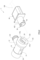
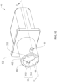
- a gas switching device 1 according to an embodiment of the present invention is illustrated in FIG. 1 to FIG. 13 and includes a valve body 10, a switching assembly 28, and a manipulating member 46 with the essential features of the gas switching device 1 according to the present invention being set forth in appended claim 1.
- the valve body 10 has an inlet portion 12 and an outlet portion 14, wherein the inlet portion 12 is tubular and has an external threaded section 122 for engaging with a gas supplying tube (not shown).
- the inlet portion 12 has an inlet passage 124 for injecting gas and extends in a first axial direction X.
- the outlet portion 14 is tubular and is connected to the inlet portion 12, wherein the outlet portion 14 extends in a second axial direction Y which intersects the first axial direction X.
- the second axial direction Y is substantially perpendicular to the first axial direction X.
- the outlet portion 14 has an outlet port 142 for connecting the manipulating member 46.
- the outlet portion 14 has a receiving hole 16, wherein the receiving hole 16 has a first section 18, a second section 20, and a third section 22 connected in sequence along an axial direction thereof.
- the outlet port 142 is located at the first section 18.
- the first section 18 has a connecting passage 182.
- the second section 20 is located between the first section 18 and the third section 22 and forms a receiving chamber, wherein a hole wall of the second section 20 is tapered in shape. More specifically, a diameter of the second section 20 gradually decreases in a direction from the first section 18 to the third section 22.
- the hole wall of the second section 20 (i.e., a wall of the receiving chamber) has a side opening 202 communicating with the inlet passage 124.
- a junction between the third section 22 and the second section 20 has a shoulder portion 222.
- An inner wall of the connecting passage 182 i.e., a hole wall of the first section 18
- An end portion of the outlet port 142 has at least one recess 142a.
- a number of the at least one recess 142a is two, and the two recesses 142a communicate with the annular groove 182a.
- the annular groove 182a has a groove wall 182b facing the second section 20.
- the outlet portion 14 has a restricting groove 24 located at a radial periphery of the third section 22 and communicating with the third section 22. Two end walls of the restricting groove 24 respectively form a first blocking portion 242 and a second blocking portion 244 (as shown in FIG. 6 ).
- the outlet portion 14 has an open end 14a at an outer side of the third section 22, and a rear cover 26 is engaged around a radial periphery of the third section 22 in a threaded way to close the open end 14a.
- the switching assembly 28 includes a plug member 30, wherein the plug member 30 has a first end 302 and a second end 304 opposite to the first end 302 in an axial direction thereof. At least a part of the plug member 30 is located in the second section 20 of the receiving hole 16.
- the plug member 30 has an axial hole 32 and a through hole 34 located in a radial direction of the plug member 30, wherein the axial hole 32 communicates with the through hole 34 and the outlet port 142.
- the plug member 30 includes a driving section 36, a tapered section 38, and an extending section 40, wherein the driving section 36 has the first end 302, and the tapered section 38 is located between the driving section 36 and the extending section 40, and the driving section 36 is located at the first section 18.
- the tapered section 38 is located at the second section 20, wherein an outer peripheral surface of the tapered section 38 matches with the hole wall of the second section 20.
- the extending section 40 is located at the third section 22 and has the second end 304.
- the axial hole 32 has an open side 322 and a close side 324, wherein the open side 322 is formed at the first end 302, and the close side 324 is located at the tapered section 38 and is located between the first end 302 and the second end 304.
- the through hole 34 is located on the tapered section 38.
- the first end 302 has at least one notch 302a.
- a number of the at least one notch 302a is two, wherein the two notches 302a are located at two opposite sides of a radial periphery of the axial hole 32.
- the annular groove 182a of the outlet port 142 surrounds a radial periphery of the two notches 302a.
- the switching assembly 28 further includes an elastic member 42, wherein an end of the elastic member 42 abuts against the shoulder portion 222, while another end of the elastic member 42 exerts a force on the extending section 40 in a direction away from the shoulder portion 222, so that the outer peripheral surface of the tapered section 38 could tightly abut against the hole wall of the second section 20.
- the switching assembly 28 includes a blocking member which is a blocking rod 44 as an example, wherein the blocking rod 44 is disposed at the extending section 40 of the plug member 30 and extends in a radial periphery of the extending section 40. Another end of the elastic member 42 abuts against the blocking rod 44.
- the elastic member 42 includes a spring 424 and two blocking plates 422 fitting around the extending section 40, wherein the spring 424 is located between the two blocking plates 422.
- One of the blocking plates 422 forms an end of the elastic member 42 and abuts against the shoulder portion 222, while the other blocking plate 422 forms another end of the elastic member 42 and abuts against the blocking rod 44.
- An end of the blocking rod 44 extends into the restricting groove 24 and is located between the first blocking portion 242 and the second blocking portion 244 for restricting a rotation angle of the plug member 30.
- the plug member 30 is manipulable to turn in the axial direction of the plug member 30 between a first position P1 and a second position P2.
- the plug member 44 when the plug member 44 is at the first position P1, the outer peripheral surface of the tapered section 38 of the plug member 30 closes the side opening 202 to block the output gas, and the notches 302a on the first end 302 of the plug member 30 and the recess 142a of the outlet port 142 are located at the same reference plane (as shown in FIG. 5 ), and the blocking rod 44 abuts against the first blocking portion 242.
- the manipulating member 46 has a connecting end 462 and has a gas passage 48 therein.
- An end of the gas passage 48 forms an inlet 482 at the connecting end 462, while another end of the gas passage 48 is adapted to communicate with a gas pipe 100, wherein the gas pipe 100 could be a hose and be connected to a gas apparatus.
- the manipulating member 46 is detachably connected to the outlet port 142 via the connecting end 462, and the connecting end 462 is connected to the plug member 30, and the gas passage 48 communicates with the axial hole 32.
- the manipulating member 46 drives the plug member 30 to turn between the first position P1 and the second position P2.
- the connecting end 462 of the manipulating member 46 is configured with at least one positioning member 50.
- a number of the at least one positioning member 50 is two.
- the positioning members 50 are disposed in a radial direction of the connecting end 462, wherein each of the positioning members 50 has an outer end 502 protruding out of a radial periphery of the connecting end 462 and an inner end 504 located in the gas passage 48.
- a sealing member 52 is disposed in the gas passage 48 and has a through hole 522 communicating with the gas passage 48.
- the plug member 30 When the plug member 30 is located at the first position P1 and the connecting end 462 is connected to the plug member 30, the outer end 502 of each of the positioning members 50 enters the annular groove 182a via one of the recesses 142a, and the inner end 504 of each of the positioning members 50 enters one of the notches 302a.
- the first end 302 of the plug member 30 is located in the gas passage 48 and abuts against the sealing member 52.
- the open side 322 of the axial hole 32 communicates with the through hole 522 and the gas passage 48.
- each of the positioning members 50 When the user turns the manipulating member 46, the inner end 504 of each of the positioning members 50 abuts against a wall of each of the notches 302a to drive the plug member 30 to turn to the second position P2 in the axial direction thereof.
- the groove wall 182b of the annular groove 182a restricts the outer end 502 of each positioning member 50 to the annular groove 182a (as shown at the dotted line in FIG. 12 ).
- the annular groove 182a restricts the manipulating member 46 from disengaging, and the first end 302 of the plug member 30 stably abuts against the sealing member 52, thereby the output gas outputted from the axial hole 32 of the plug member 30 could enter the gas passage 48 of the manipulating member 46 to be transmitted to the gas pipe 100.
- the manipulating member 46 When the user does not use gas, the manipulating member 46 could be turned in a reverse direction, and the plug member 30 could be turned back to the first position P1, so that the plug member 30 could block the gas, and the manipulating member 46 could be removed from the outlet port 142 of the valve body 10.
- the manipulating member 46 it is more convenient to use the output gas by using the manipulating member 46 to turn the plug member 30 to allow the output gas to be transmitted to the gas pipe 100 via the gas passage 48 in the manipulating member 46. After use, the manipulating member 46 could be removed together with the gas pipe 100. Additionally, since the plug member 30 is in the valve body 10, the plug member 30 would not be touched by mistake to lead to a problem that the output gas leaks from the outlet port 142, which enhances a safety of use.
Landscapes
- Engineering & Computer Science (AREA)
- General Engineering & Computer Science (AREA)
- Mechanical Engineering (AREA)
- Multiple-Way Valves (AREA)
- Glass Compositions (AREA)
- Crystals, And After-Treatments Of Crystals (AREA)
- Taps Or Cocks (AREA)
- Valve Housings (AREA)
Claims (7)
- Dispositif de commutation de gaz (1), comprenant :un corps de vanne (10) comportant une partie d'entrée (12) et une partie de sortie (14), dans lequel la partie d'entrée (12) comporte un passage d'entrée (124) pour l'injection de gaz ; la partie de sortie (14) comporte un orifice de sortie (142) et une chambre de réception ; une paroi de la chambre de réception comporte une ouverture latérale (202) communiquant avec le passage d'entrée (124) ;un ensemble de commutation (28) comprenant un élément bouchon (30) situé dans la chambre de réception, dans lequel l'élément bouchon (30) présente un trou traversant (34) situé dans une direction radiale de l'élément bouchon (30) et un trou axial (32) communiquant avec le trou traversant (34) et l'orifice de sortie (142) ; l'élément bouchon (30) peut être tourné entre une première position (P1) et une deuxième position (P2) dans une direction axiale de l'élément bouchon (30) ; lorsque l'élément bouchon (30) est dans la première position (P1), une surface périphérique extérieure de l'élément bouchon (30) ferme l'ouverture latérale (202) ; lorsque l'élément bouchon (30) est dans la deuxième position (P2), le trou traversant (34) communique avec l'ouverture latérale (202) ; etun élément de manipulation (46) ayant une extrémité de connexion (462) et comportant un passage de gaz (48) à son intérieur, dans lequel une extrémité du passage de gaz (48) forme une entrée (482) à l'extrémité de connexion (462), et une autre extrémité du passage de gaz (48) est adaptée pour communiquer avec un tuyau de gaz (100) ; l'élément de manipulation (46) est relié de manière amovible à l'orifice de sortie (142) par l'intermédiaire de l'extrémité de connexion (462) ; l'extrémité de connexion (462) est reliée à l'élément bouchon (30), et le passage de gaz (48) communique avec le trou axial (32) ; l'élément de manipulation (46) entraîne l'élément bouchon (30) à tourner entre la première position (P1) et la deuxième position (P2) ;dans lequel au moins un élément de positionnement (50) est disposé sur l'extrémité de connexion (462) de l'élément de manipulation (46) ; l'orifice de sortie (142) du corps de vanne (10) comporte un passage de connexion (182) ; une paroi interne du passage de connexion (182) comporte une rainure annulaire (182a) ; une partie d'extrémité de l'orifice de sortie (142) présente au moins un renfoncement (142a) communiquant avec la rainure annulaire (182a) ; ledit au moins un élément de positionnement (50) entre dans la rainure annulaire (182a) par l'intermédiaire de l'au moins un renfoncement (142a) ;dans lequel l'élément bouchon (30) présente une première extrémité (302) et une deuxième extrémité (304) opposée à la première extrémité (302) dans une direction axiale de l'élément bouchon (30) ; le trou axial (32) présente un côté ouvert (322) formé à la première extrémité (302) et un côté fermé (324) situé entre la première extrémité (302) et la deuxième extrémité (304) ; la première extrémité (302) présente au moins une encoche (302a) ; la rainure annulaire (182a) entoure une périphérie radiale de ladite au moins une encoche (302a) ; lorsque l'élément bouchon (30) est situé dans la première position (P1), ledit au moins un élément de positionnement (50) entre dans ladite au moins une encoche (302a) par l'intermédiaire dudit au moins un renfoncement (142a) et est adapté pour entraîner l'élément bouchon (30) à tourner vers la deuxième position (P2) le long de la direction axiale de l'élément bouchon (30) ;dans lequel ledit au moins un élément de positionnement (50) est disposé dans une direction radiale de l'extrémité de connexion (462) et présente une extrémité extérieure (502) faisant saillie hors d'une périphérie radiale de l'extrémité de connexion (462) et une extrémité intérieure (504) située dans le passage de gaz (48) ; lorsque l'extrémité de connexion (462) est connectée à l'élément bouchon (30), la première extrémité (302) de l'élément bouchon (30) est située dans le passage de gaz (48), et l'extrémité intérieure (504) dudit au moins un élément de positionnement (50) entre dans ladite au moins une encoche (302a), et l'extrémité extérieure (502) dudit au moins un élément de positionnement (50) entre dans la rainure annulaire (182a).
- Dispositif de commutation de gaz (1) selon la revendication 1, dans lequel un élément d'étanchéité (52) est disposé dans le passage de gaz (48) et présente un trou traversant (522) communiquant avec le passage de gaz (48) ; lorsque l'extrémité de connexion (462) est connectée à l'élément bouchon (30), la première extrémité (302) de l'élément bouchon (30) vient en butée contre l'élément d'étanchéité (52), et le côté ouvert (322) du trou axial (32) communique avec le trou traversant (522).
- Dispositif de commutation de gaz (1) selon la revendication 1, dans lequel, lorsque ledit au moins un élément de positionnement (50) entraîne l'élément bouchon (30) pour tourner vers la deuxième position (P2) le long de la direction axiale de l'élément bouchon (30), une paroi de rainure (182b) de la rainure annulaire (182a) restreint ledit au moins un élément de positionnement (50) dans la rainure annulaire (182a).
- Dispositif de commutation de gaz (1) selon la revendication 1, dans lequel la partie de sortie (14) comporte un trou de réception (16) ; le trou de réception (16) comporte une première section (18), une deuxième section (20) et une troisième section (22) ; la première section (18) comporte le passage de connexion (182) ; la deuxième section (20) est située entre la première section (18) et la troisième section (22) ; une paroi de trou de la deuxième section (20) est de forme conique et forme la chambre de réception, et un diamètre de la deuxième section (20) diminue progressivement dans une direction allant de la première section (18) à la troisième section (22) ; une jonction entre la troisième section (22) et la deuxième section (20) présente une partie d'épaulement (222) ; l'élément bouchon (30) comprend une section conique (38) et une section d'extension (40) ; une surface périphérique extérieure de la section conique (38) correspond à la paroi de trou de la deuxième section (20) ; le trou traversant (34) est situé sur la section conique (38) ; la section d'extension (40) est reliée à la section conique (38) et est située au niveau de la troisième section (22) du trou de réception (16) ; l'ensemble de commutation (28) comprend un élément élastique (42) ; une extrémité de l'élément élastique (42) vient en butée contre la partie d'épaulement (222), tandis qu'une autre extrémité de l'élément élastique (42) exerce une force sur la section d'extension (40) dans une direction s'écartant de la partie d'épaulement (222), de sorte que la surface périphérique extérieure de la section conique (38) vient en butée contre la paroi de trou de la deuxième section (20).
- Dispositif de commutation de gaz (1) selon la revendication 4, dans lequel l'ensemble de commutation (28) comprend un élément de blocage disposé au niveau de la section d'extension (40) de l'élément bouchon (30) ; l'autre extrémité de l'élément élastique (42) vient en butée contre l'élément de blocage.
- Dispositif de commutation de gaz (1) selon la revendication 5, dans lequel l'élément élastique (42) comprend deux plaques de blocage (422) et un ressort (424) ; les deux plaques de blocage (422) s'adaptent autour de la section d'extension (40), et l'une des plaques de blocage (422) vient en butée contre la partie d'épaulement (222), tandis que l'autre plaque de blocage (422) vient en butée contre l'élément de blocage ; le ressort (424) s'adapte autour de la section d'extension (40) et est situé entre les deux plaques de blocage (422).
- Dispositif de commutation de gaz (1) selon la revendication 5, dans lequel la partie de sortie (14) du corps de vanne (10) présente une rainure de restriction (24) communiquant avec la troisième section (22) du trou de réception (16) ; la rainure de restriction (24) présente une première partie de blocage (242) et une deuxième partie de blocage (244) ; l'élément de blocage entre dans la rainure de restriction (24) ; lorsque l'élément bouchon (30) est tourné vers la première position (P1), l'élément de blocage vient en butée contre la première partie de blocage (242) ; lorsque l'élément bouchon (30) est tourné vers la deuxième position (P2), l'élément de blocage vient en butée contre la deuxième partie de blocage (244).
Applications Claiming Priority (1)
| Application Number | Priority Date | Filing Date | Title |
|---|---|---|---|
| TW110130064A TWI784666B (zh) | 2021-08-16 | 2021-08-16 | 瓦斯開關裝置 |
Publications (3)
| Publication Number | Publication Date |
|---|---|
| EP4137733A1 EP4137733A1 (fr) | 2023-02-22 |
| EP4137733B1 true EP4137733B1 (fr) | 2024-11-27 |
| EP4137733C0 EP4137733C0 (fr) | 2024-11-27 |
Family
ID=82399382
Family Applications (1)
| Application Number | Title | Priority Date | Filing Date |
|---|---|---|---|
| EP22183311.4A Active EP4137733B1 (fr) | 2021-08-16 | 2022-07-06 | Dispositif de commutation de gaz |
Country Status (2)
| Country | Link |
|---|---|
| EP (1) | EP4137733B1 (fr) |
| TW (1) | TWI784666B (fr) |
Family Cites Families (8)
| Publication number | Priority date | Publication date | Assignee | Title |
|---|---|---|---|---|
| GB347397A (en) * | 1930-03-07 | 1931-04-30 | George Richard Morris | Improvements relating to plug cocks for gas and other fluids |
| US3100619A (en) * | 1957-04-29 | 1963-08-13 | Berghofer Hans | Gas connection tap with hose connection part |
| DE2135819B2 (de) * | 1971-07-17 | 1973-08-23 | Sicherheits-schlauchanschlusshahn | |
| US3826464A (en) * | 1973-04-09 | 1974-07-30 | H Berghofer | Disengageable safety coupling for conduits |
| JP3660164B2 (ja) * | 1999-07-14 | 2005-06-15 | リンナイ株式会社 | ガスコック |
| WO2014058716A1 (fr) * | 2012-10-10 | 2014-04-17 | Illinois Tool Works Inc. | Système de soupape pour gazinière à commutateur d'allumage intégré |
| TWI576544B (zh) * | 2014-09-02 | 2017-04-01 | Grand Mate Co Ltd | The switchgear of the gas furnace |
| TWI623710B (zh) * | 2017-04-21 | 2018-05-11 | Grand Mate Co Ltd | 瓦斯開關裝置 |
-
2021
- 2021-08-16 TW TW110130064A patent/TWI784666B/zh active
-
2022
- 2022-07-06 EP EP22183311.4A patent/EP4137733B1/fr active Active
Also Published As
| Publication number | Publication date |
|---|---|
| EP4137733A1 (fr) | 2023-02-22 |
| TWI784666B (zh) | 2022-11-21 |
| EP4137733C0 (fr) | 2024-11-27 |
| TW202309448A (zh) | 2023-03-01 |
Similar Documents
| Publication | Publication Date | Title |
|---|---|---|
| CN111750134B (zh) | 一种阀门及淋浴装置 | |
| JP5581525B2 (ja) | 管継手 | |
| WO2009002417A4 (fr) | Soupapes destinées à être utilisées avec un chauffe-eau sans réservoir | |
| US5553638A (en) | Pressure-loaded cylinder valve insert | |
| ES2667206T3 (es) | Acoplamiento de manguera | |
| US20120266993A1 (en) | Wall-Mounted Faucet that is Available for Water Supply Lines of Different Specifications and Sizes | |
| ES2322856T3 (es) | Union para tubos encajable y bloqueable. | |
| EP4137733B1 (fr) | Dispositif de commutation de gaz | |
| TWI397648B (zh) | 氣體裝置 | |
| JP6249993B2 (ja) | 高圧流体を扱うのに適した雌型継手部材及びそれを備える管継手 | |
| US5020563A (en) | Connector set | |
| US11572955B1 (en) | Gas switching device | |
| JP2001200943A (ja) | ガス栓 | |
| KR20150088463A (ko) | 앵글밸브 | |
| CN213397538U (zh) | 一种内窥镜电气接口密封测漏器 | |
| JP4639181B2 (ja) | ガスソケット | |
| US6453489B1 (en) | Faucet coupling device for coupling to various members | |
| CN115569749A (zh) | 一种花洒 | |
| CN204756236U (zh) | 联接器 | |
| US7124453B2 (en) | Connecting device for connecting a shower head assembly to a wall-mount water supplying pipe | |
| JP2005245668A (ja) | 内視鏡の送水管路洗浄用コネクタ | |
| JP2002081590A (ja) | 給水栓 | |
| JP2003185097A (ja) | 液化石油ガス容器用バルブ | |
| US20090060628A1 (en) | Flow-Through Type Washing Device | |
| CN210978633U (zh) | 带接管的分流式角阀组件 |
Legal Events
| Date | Code | Title | Description |
|---|---|---|---|
| PUAI | Public reference made under article 153(3) epc to a published international application that has entered the european phase |
Free format text: ORIGINAL CODE: 0009012 |
|
| STAA | Information on the status of an ep patent application or granted ep patent |
Free format text: STATUS: THE APPLICATION HAS BEEN PUBLISHED |
|
| AK | Designated contracting states |
Kind code of ref document: A1 Designated state(s): AL AT BE BG CH CY CZ DE DK EE ES FI FR GB GR HR HU IE IS IT LI LT LU LV MC MK MT NL NO PL PT RO RS SE SI SK SM TR |
|
| P01 | Opt-out of the competence of the unified patent court (upc) registered |
Effective date: 20230630 |
|
| STAA | Information on the status of an ep patent application or granted ep patent |
Free format text: STATUS: REQUEST FOR EXAMINATION WAS MADE |
|
| 17P | Request for examination filed |
Effective date: 20230817 |
|
| RBV | Designated contracting states (corrected) |
Designated state(s): AL AT BE BG CH CY CZ DE DK EE ES FI FR GB GR HR HU IE IS IT LI LT LU LV MC MK MT NL NO PL PT RO RS SE SI SK SM TR |
|
| GRAP | Despatch of communication of intention to grant a patent |
Free format text: ORIGINAL CODE: EPIDOSNIGR1 |
|
| STAA | Information on the status of an ep patent application or granted ep patent |
Free format text: STATUS: GRANT OF PATENT IS INTENDED |
|
| INTG | Intention to grant announced |
Effective date: 20240619 |
|
| GRAS | Grant fee paid |
Free format text: ORIGINAL CODE: EPIDOSNIGR3 |
|
| GRAA | (expected) grant |
Free format text: ORIGINAL CODE: 0009210 |
|
| STAA | Information on the status of an ep patent application or granted ep patent |
Free format text: STATUS: THE PATENT HAS BEEN GRANTED |
|
| AK | Designated contracting states |
Kind code of ref document: B1 Designated state(s): AL AT BE BG CH CY CZ DE DK EE ES FI FR GB GR HR HU IE IS IT LI LT LU LV MC MK MT NL NO PL PT RO RS SE SI SK SM TR |
|
| REG | Reference to a national code |
Ref country code: GB Ref legal event code: FG4D |
|
| REG | Reference to a national code |
Ref country code: CH Ref legal event code: EP |
|
| REG | Reference to a national code |
Ref country code: DE Ref legal event code: R096 Ref document number: 602022008101 Country of ref document: DE |
|
| REG | Reference to a national code |
Ref country code: IE Ref legal event code: FG4D |
|
| U01 | Request for unitary effect filed |
Effective date: 20241213 |
|
| U07 | Unitary effect registered |
Designated state(s): AT BE BG DE DK EE FI FR IT LT LU LV MT NL PT RO SE SI Effective date: 20250102 |
|
| P04 | Withdrawal of opt-out of the competence of the unified patent court (upc) registered |
Free format text: CASE NUMBER: APP_67424/2024 Effective date: 20241220 |
|
| PG25 | Lapsed in a contracting state [announced via postgrant information from national office to epo] |
Ref country code: IS Free format text: LAPSE BECAUSE OF FAILURE TO SUBMIT A TRANSLATION OF THE DESCRIPTION OR TO PAY THE FEE WITHIN THE PRESCRIBED TIME-LIMIT Effective date: 20250327 Ref country code: HR Free format text: LAPSE BECAUSE OF FAILURE TO SUBMIT A TRANSLATION OF THE DESCRIPTION OR TO PAY THE FEE WITHIN THE PRESCRIBED TIME-LIMIT Effective date: 20241127 |
|
| PG25 | Lapsed in a contracting state [announced via postgrant information from national office to epo] |
Ref country code: ES Free format text: LAPSE BECAUSE OF FAILURE TO SUBMIT A TRANSLATION OF THE DESCRIPTION OR TO PAY THE FEE WITHIN THE PRESCRIBED TIME-LIMIT Effective date: 20241127 |
|
| PG25 | Lapsed in a contracting state [announced via postgrant information from national office to epo] |
Ref country code: NO Free format text: LAPSE BECAUSE OF FAILURE TO SUBMIT A TRANSLATION OF THE DESCRIPTION OR TO PAY THE FEE WITHIN THE PRESCRIBED TIME-LIMIT Effective date: 20250227 |
|
| PG25 | Lapsed in a contracting state [announced via postgrant information from national office to epo] |
Ref country code: GR Free format text: LAPSE BECAUSE OF FAILURE TO SUBMIT A TRANSLATION OF THE DESCRIPTION OR TO PAY THE FEE WITHIN THE PRESCRIBED TIME-LIMIT Effective date: 20250228 |
|
| PG25 | Lapsed in a contracting state [announced via postgrant information from national office to epo] |
Ref country code: PL Free format text: LAPSE BECAUSE OF FAILURE TO SUBMIT A TRANSLATION OF THE DESCRIPTION OR TO PAY THE FEE WITHIN THE PRESCRIBED TIME-LIMIT Effective date: 20241127 |
|
| PG25 | Lapsed in a contracting state [announced via postgrant information from national office to epo] |
Ref country code: RS Free format text: LAPSE BECAUSE OF FAILURE TO SUBMIT A TRANSLATION OF THE DESCRIPTION OR TO PAY THE FEE WITHIN THE PRESCRIBED TIME-LIMIT Effective date: 20250227 |
|
| PG25 | Lapsed in a contracting state [announced via postgrant information from national office to epo] |
Ref country code: SM Free format text: LAPSE BECAUSE OF FAILURE TO SUBMIT A TRANSLATION OF THE DESCRIPTION OR TO PAY THE FEE WITHIN THE PRESCRIBED TIME-LIMIT Effective date: 20241127 |
|
| PG25 | Lapsed in a contracting state [announced via postgrant information from national office to epo] |
Ref country code: SK Free format text: LAPSE BECAUSE OF FAILURE TO SUBMIT A TRANSLATION OF THE DESCRIPTION OR TO PAY THE FEE WITHIN THE PRESCRIBED TIME-LIMIT Effective date: 20241127 |
|
| PG25 | Lapsed in a contracting state [announced via postgrant information from national office to epo] |
Ref country code: CZ Free format text: LAPSE BECAUSE OF FAILURE TO SUBMIT A TRANSLATION OF THE DESCRIPTION OR TO PAY THE FEE WITHIN THE PRESCRIBED TIME-LIMIT Effective date: 20241127 |
|
| U20 | Renewal fee for the european patent with unitary effect paid |
Year of fee payment: 4 Effective date: 20250624 |
|
| PLBE | No opposition filed within time limit |
Free format text: ORIGINAL CODE: 0009261 |
|
| STAA | Information on the status of an ep patent application or granted ep patent |
Free format text: STATUS: NO OPPOSITION FILED WITHIN TIME LIMIT |
|
| REG | Reference to a national code |
Ref country code: CH Ref legal event code: L10 Free format text: ST27 STATUS EVENT CODE: U-0-0-L10-L00 (AS PROVIDED BY THE NATIONAL OFFICE) Effective date: 20251008 |
|
| 26N | No opposition filed |
Effective date: 20250828 |
|
| REG | Reference to a national code |
Ref country code: CH Ref legal event code: H13 Free format text: ST27 STATUS EVENT CODE: U-0-0-H10-H13 (AS PROVIDED BY THE NATIONAL OFFICE) Effective date: 20260224 |