EP4137589B1 - Gerbtrommel mit einer struktur mit voneinander beabstandeten hydrophilen und hydrophoben oberflächen - Google Patents
Gerbtrommel mit einer struktur mit voneinander beabstandeten hydrophilen und hydrophoben oberflächen Download PDFInfo
- Publication number
- EP4137589B1 EP4137589B1 EP22768604.5A EP22768604A EP4137589B1 EP 4137589 B1 EP4137589 B1 EP 4137589B1 EP 22768604 A EP22768604 A EP 22768604A EP 4137589 B1 EP4137589 B1 EP 4137589B1
- Authority
- EP
- European Patent Office
- Prior art keywords
- hydrophilic
- hydrophobic
- drum body
- wall
- leather
- Prior art date
- Legal status (The legal status is an assumption and is not a legal conclusion. Google has not performed a legal analysis and makes no representation as to the accuracy of the status listed.)
- Active
Links
Images









Classifications
-
- C—CHEMISTRY; METALLURGY
- C14—SKINS; HIDES; PELTS; LEATHER
- C14C—CHEMICAL TREATMENT OF HIDES, SKINS OR LEATHER, e.g. TANNING, IMPREGNATING, FINISHING; APPARATUS THEREFOR; COMPOSITIONS FOR TANNING
- C14C15/00—Apparatus for chemical treatment or washing of hides, skins, or leather
-
- B—PERFORMING OPERATIONS; TRANSPORTING
- B01—PHYSICAL OR CHEMICAL PROCESSES OR APPARATUS IN GENERAL
- B01F—MIXING, e.g. DISSOLVING, EMULSIFYING OR DISPERSING
- B01F29/00—Mixers with rotating receptacles
- B01F29/40—Parts or components, e.g. receptacles, feeding or discharging means
- B01F29/401—Receptacles, e.g. provided with liners
- B01F29/40231—Surface characteristics, e.g. coated, rough
-
- B—PERFORMING OPERATIONS; TRANSPORTING
- B01—PHYSICAL OR CHEMICAL PROCESSES OR APPARATUS IN GENERAL
- B01F—MIXING, e.g. DISSOLVING, EMULSIFYING OR DISPERSING
- B01F29/00—Mixers with rotating receptacles
- B01F29/60—Mixers with rotating receptacles rotating about a horizontal or inclined axis, e.g. drum mixers
- B01F29/63—Mixers with rotating receptacles rotating about a horizontal or inclined axis, e.g. drum mixers with fixed bars, i.e. stationary, or fixed on the receptacle
Definitions
- the present invention relates to the technical field of leather manufacturing industry, in particular to a leather-manufacturing rotary drum having an alternate hydrophilic and hydrophobic surface structure.
- the invention is set out in the appended set of claims.
- Leather manufacturing is a process of tanning hides and skins into leather, in which hair and non-collagenous fibers, etc. are removed to moderately loosen, fix and strengthen collagen fibers in dermis, and then a series of chemical (including biochemical) and mechanical treatments such as finishing (trimming) are carried out.
- a leather manufacturing process is generally divided into four stages, that is, preparation, tanning, post-tanning and dry finishing. Since soaking, liming, dehairing, bating, pickling, tanning, dyeing, fatliquoring, and other procedures are required to be completed in a rotary drum, the rotary drum becomes an apparatus used mostly in the leather manufacturing process.
- a mechanical action of the rotary drum promotes uniform permeation of various chemical materials, such that a chemical action of preparations is applied on the hides and skins.
- Patent document CN 211 999 784 U discloses a sheep shearing leather tanning drum based on PLC control.
- Patent document EP 1 540 022 A1 discloses improvements in drums used for the treatment of skins, leathers and like, which concern the shape and relative location of the shelves provided in such drums.
- An embodiment of the present invention provides a leather-manufacturing rotary drum having an alternate hydrophilic and hydrophobic surface structure, which can realize a more efficient and greener leather manufacturing process without reducing the quality of leather, and save time and costs, so as to solve the above problems.
- an embodiment of the present invention provides a leather-manufacturing rotary drum having an alternate hydrophilic and hydrophobic surface structure.
- the rotary drum comprises:
- the alternate hydrophilic and hydrophobic surface structure is a structure in which hydrophilic coatings and hydrophobic coatings are alternately distributed, wherein:
- the alternate hydrophilic and hydrophobic surface structure is a structure in which hydrophilic coatings and polished original surfaces of the inner wall of the drum body and/or the stirring structure are alternately distributed, wherein:
- the alternate hydrophilic and hydrophobic surface structure is a structure formed by assembling a plurality of modularized hydrophilic and hydrophobic sheets, wherein: the hydrophilic and hydrophobic material are alternately distributed to form a sheet with the hydrophilic-material and the hydrophobic-material, and the modularized hydrophilic and hydrophobic sheets are then mounted in close contact with the surface of the inner wall of the drum body and/or the surface of the stirring structure.
- the alternate hydrophilic and hydrophobic surface structure is a structure in which modularized hydrophilic sheets and hydrophobic coatings are alternately distributed, wherein:
- the alternate hydrophilic and hydrophobic surface structure is a structure in which modularized hydrophilic sheets and polished original surfaces of the inner wall of the drum body and/or the stirring structure are alternately distributed, wherein:
- the alternate hydrophilic and hydrophobic surface structure is a structure in which hydrophilic coatings and modularized hydrophobic sheets are alternately distributed, wherein:
- the alternate hydrophilic and hydrophobic surface structure is a structure in which modularized hydrophilic sheets and modularized hydrophobic sheets are alternately distributed, wherein:
- the stirring structure comprises baffles and/or protruding piles, and in the rotating process of the drum body, the baffles and/or the protruding piles repeatedly enter and leave the bath liquid in the drum body.
- the stirring structure comprises both the baffles and the protruding piles
- the baffles and the protruding piles are alternately distributed along a circumferential wall surface of the drum body.
- the leather-manufacturing rotary drum in the embodiments of the present invention comprises a drum body capable of rotating in its own circumferential direction, a stirring structure arranged in the drum body, and an alternate hydrophilic and hydrophobic surface structure in which hydrophilic-material surfaces and hydrophobic-material surfaces are alternately distributed, the alternate hydrophilic and hydrophobic surface structure being distributed on a surface of an inner wall of the drum body and/or a surface of the stirring structure, wherein, in a rotating process of the drum body, the alternate hydrophilic and hydrophobic surface structure repeatedly enters and leaves a bath liquid in the drum body, so that a wetting behavior of the surface of the inner wall of the drum body and/or the surface of the stirring structure can be changed, so as to indirectly adjust a surface acting force between the inner wall of the drum body and/or the stirring structure and leather, thereby achieving a gain effect of optimizing a leather manufacturing process.
- an effective action area during leather manufacturing is enlarged and relative leather manufacturing time is prolonged without reducing the quality of the leather, thereby realizing a more efficient leather manufacturing process, and saving time and costs.
- a stirring action of the surface of the inner wall of the drum body and/or the stirring structure on the bath liquid can be enhanced, such that flow of the bath liquid on a surface of the leather is accelerated, permeation and mass transfer of chemicals towards the interior of the leather are promoted, and acting time is shortened.
- the present invention provides a leather-manufacturing rotary drum having an alternate hydrophilic and hydrophobic surface structure.
- the alternate hydrophilic and hydrophobic surface structure 3 is distributed on a surface of an inner wall of a drum body 1 of the leather-manufacturing rotary drum and/or a surface of a stirring structure 2 in the drum body.
- Hydrophilic-material surfaces 31 in the alternate hydrophilic and hydrophobic surface structure 3 may increase an adhesive force to droplets
- hydrophobic-material surfaces 32 may increase a driving force for gathering droplets and promote more droplets to move to the hydrophilic-material surfaces 31.
- the hydrophilic and hydrophobic surfaces are not directly used to simply change the characteristics of fluid, but a surface acting force between the inner wall of the drum body 1 and/or the stirring structure 2 and leather is indirectly adjusted by changing a wetting behavior of the surface of the inner wall of the drum body 1 and/or the surface of the stirring structure 2, so as to achieve a gain effect of optimizing a leather manufacturing process.
- a leather manufacturing area is enlarged and effective leather manufacturing time is prolonged without reducing the quality of the leather, thereby realizing a more efficient leather manufacturing process, and saving time and costs.
- the surface of the inner wall of the drum body 1 and/or the surface of the stirring structure 2 provided with the alternate hydrophilic and hydrophobic surface structure 3 may draw the leather to enter and leave the bath liquid together, so as to enhance a stirring action of the surface of the inner wall of the drum body 1 and/or the stirring structure 2 on the bath liquid, such that flow of the bath liquid on a surface of the leather is accelerated, permeation and mass transfer of chemicals towards the interior of the leather are promoted, and acting time is shortened.
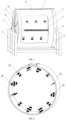
- FIG. 1 a schematic diagram of an overall structure of a leather-manufacturing rotary drum having an alternate hydrophilic and hydrophobic surface structure in an embodiment of the present invention is shown.
- the leather-manufacturing rotary drum comprises:
- the structure of the drum body 1 capable of rotating in its own circumferential direction and the stirring structure 2 arranged in the drum body 1 are not specifically limited in the present invention, as long as they can be used in leather manufacturing industry and can realize at least one processing procedure such as soaking, liming, dehairing, bating, pickling, tanning, dyeing and fatliquoring.
- the stirring structure 2 may comprise baffles 21 and/or protruding piles 22, and in the rotating process of the drum body 1, the baffles 21 and/or the protruding piles 22 repeatedly enter and leave the bath liquid in the drum body 1. That is, the stirring structure 2 may only comprise the baffles 21, or only comprise the protruding piles 22, or comprise both the baffles 21 and the protruding piles 22.
- An alternate hydrophilic and hydrophobic arrangement of the baffles 21 and the protruding piles 22 can better draw the leather, so as to enhance a stirring action on the bath liquid, and enhance application of impacting, colliding, rubbing, kneading and other actions to hides and skins, thereby enhancing flow of the bath liquid on the surface of the leather, and promoting permeation and mass transfer of chemicals towards the interior of the leather.
- the stirring structure 2 comprises both the baffles 21 and the protruding piles 22
- the baffles 21 and the protruding piles 22 are alternately distributed along a circumferential wall surface of the drum body 1.
- the alternate hydrophilic and hydrophobic surface structure 3 may be understood as a surface of which hydrophilic materials and hydrophobic materials are alternately distributed, a contact angle of a droplet at a three-phase intersection of the hydrophilic-material surface 31 is less than 90 degrees, a contact angle of a droplet at a three-phase intersection of the hydrophobic-material surface 32 is greater than 90 degrees, and alternate distribution of the hydrophilic and hydrophobic materials may achieve an effect that droplets are better adhered to the hydrophilic-material surfaces 31.
- the alternate hydrophilic and hydrophobic surface structure 3 may repeatedly enter and leave the bath liquid in the drum body 1 along with the surface of the inner wall of the drum body 1 and/or the stirring structure 2.
- the hydrophilic-material surfaces 31 may increase an adhesive force of the surface of the inner wall of the drum body 1 and/or the stirring structure 2 to droplets of the bath liquid on the basis of hydrophilic characteristics of the hydrophilic-material surfaces
- the hydrophobic-material surfaces 32 may increase a driving force of the surface of the inner wall of the drum body 1 and/or the stirring structure 2 for gathering droplets of the bath liquid on the basis of hydrophobic characteristics of the hydrophobic-material surfaces.
- the distribution of the alternate hydrophilic and hydrophobic surface structure 3 on the surface of the inner wall of the drum body 1 and/or the surface of the stirring structure 2 may be divided into the following three situations: in a first situation, as shown in FIGS. 1 and 2 , the alternate hydrophilic and hydrophobic surface structure 3 is only distributed on the surface of the stirring structure 2; in a second situation, as shown in FIG. 3 , the alternate hydrophilic and hydrophobic surface structure 3 is only distributed on the surface of the inner wall of the drum body 1; and in a third situation, as shown in FIG. 4 , the alternate hydrophilic and hydrophobic surface structure 3 is distributed on both the surface of the inner wall of the drum body 1 and the surface of the stirring structure 2.
- distribution herein may be understood as that the alternate hydrophilic and hydrophobic surface structure 3 is partially or completely wrapped around the surface of the inner wall of the drum body 1 and/or the surface of the stirring structure 2.
- FIG. 5(a) a gain principle of a baffle 21 having an alternate hydrophilic and hydrophobic surface structure 3 leaving a bath liquid is shown; and as shown in FIG. 5(b) , a gain principle of a protruding pile 22 having an alternate hydrophilic and hydrophobic surface structure 3 leaving a bath liquid is shown), and a gain principle of a stirring structure 2 having an alternate hydrophilic and hydrophobic surface structure 3 entering a bath liquid is shown (as shown in FIG. 6(a) , a gain principle of a baffle 21 having an alternate hydrophilic and hydrophobic surface structure 3 entering a bath liquid is shown; and as shown in FIG. 6(b) , a gain principle of a protruding pile 22 having an alternate hydrophilic and hydrophobic surface structure 3 entering a bath liquid is shown).
- the stirring structure 2 impacts the bath liquid, an inertial force drives the bath liquid to rapidly spread on a surface of the stirring structure, and part of kinetic energy of the bath liquid is converted into surface energy and dissipation energy. Since the alternate hydrophilic and hydrophobic surface structure 3 is arranged on the surface of the stirring structure 2, the bath liquid has a large spreading area and a long spreading time consumption on the hydrophilic-material surfaces 31, and has a small spreading area and a short time consumption on the hydrophobic-material surfaces 32.
- adhesive characteristics of the bath liquid on the hydrophilic-material surfaces 31 can achieve two gain effects on the leather-manufacturing rotary drum without adversely affecting the quality of the leather: on the one hand, a contact area between the leather and the bath liquid in a rising process may be increased.
- the alternate hydrophilic and hydrophobic surface structure 3 to which the bath liquid is adhered enhances an interaction between the stirring structure 2 and the leather such that the leather may reach a higher drawing position in a rising process, the wrinkled leather may be fully extended, throwing kinetic energy of the leather is increased without increasing total energy loss, and a mass transfer action is enhanced.
- a flow field of the bath liquid at the bottom of the rotary drum may be caused to be more disordered, thereby enhancing a mass transfer action between the bath liquid and the leather.
- the leather is more likely to be drawn into the bath liquid at the bottom of the rotary drum to generate a strong stirring action, such that the flow field in the bath liquid is more disordered at the bottom, and effects of shearing a mass transfer boundary layer of the leather and thinning the mass transfer boundary layer are achieved, thereby promoting an effect of convective mass transfer action.
- This process is as shown in FIGS. 6(a) and 6(b) .
- small bumps on the baffle 21 and the protruding pile 22 represent droplets of the bath liquid adhered to the hydrophilic-material surface 31.
- hydrophilic materials and the hydrophobic materials are not limited in the present invention, as long as the hydrophilic materials can enhance an adhesive force of the surface of the inner wall of the drum body 1 and/or the stirring structure 2 on droplets of a bath liquid on the basis of hydrophilic characteristics of the hydrophilic materials, and the hydrophobic materials can increase a driving force of the bath liquid of the surface of the inner wall of the drum body 1 and/or the stirring structure 2 for gathering the droplets on the basis of hydrophobic characteristics of the hydrophobic materials.
- the hydrophilic materials may be hydrophilic metal/non-metal nanoparticles, hydrophilic resin, polyacrylic acid, silica, polyvinylpyrrolidone, and the hydrophobic materials may be alkane, oil, fluorinated polyethylene, fluorocarbon wax, or other synthetic fluoropolymer.
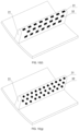
- the alternate hydrophilic and hydrophobic surface structure 3 is a structure in which hydrophilic coatings and hydrophobic coatings are alternately distributed.
- the hydrophilic coatings are the hydrophilic-material surfaces 31 and are formed by preparing hydrophilic materials on the surface of the inner wall of the drum body 1 and/or the surface of the stirring structure 2; and the hydrophobic coatings are the hydrophobic-material surfaces 32 and are formed by preparing hydrophobic materials on the surface of the inner wall of the drum body 1 and/or the surface of the stirring structure 2.
- the hydrophilic-material surfaces 31 and the hydrophobic-material surfaces 32 are both coatings, which can be understood as films applied to the surface of the inner wall of the drum body 1 and/or the surface of the stirring structure 2.
- the coatings and the surface of the inner wall of the drum body 1 and/or the surface of the stirring structure 2 may effectively form a compact composite structure, which can change surface characteristics of the material of the inner wall of the drum body 1 and/or the material of the stirring structure 2 without affecting original structures of the surface of the inner wall of the drum body 1 and/or the stirring structure 2, thereby optimizing movement of the leather on the surface of the inner wall of the drum body 1 and/or the surface of the stirring structure 2 in the leather-manufacturing rotary drum, enhancing flow of the bath liquid, and realizing a physical mechanism, principle and method for enhancing a mechanical action in a leather manufacturing process by means of the hydrophilic coatings and the hydrophobic coatings that are alternately arranged.
- FIG. 7(a) a schematic structural diagram of hydrophilic coatings and hydrophobic coatings that are alternately arranged on a surface of a protruding pile 22 is as shown in FIG. 7(a)
- a schematic structural diagram of hydrophilic coatings and hydrophobic coatings that are alternately arranged on a surface of a baffle 21 is as shown in FIG. 7(b) .
- the hydrophilic materials may be prepared on the surface of the inner wall of the drum body 1 and/or the surface of the stirring structure 2 through a spraying technology, a physical vapor deposition technology, a cathode electrochemical deposition technology, an electrophoretic directional deposition technology or a micro-contact printing technology. to form the hydrophilic coatings.
- the hydrophobic materials may be prepared on the surface of the inner wall of the drum body 1 and/or the surface of the stirring structure 2 through a spraying technology, a physical vapor deposition technology, a cathode electrochemical deposition technology, an electrophoretic directional deposition technology or a micro-contact printing technology. so as to form the hydrophobic coatings.
- coating preparation technologies used may be different. That is, in the case that different hydrophilic materials are used to prepare the hydrophilic coatings, the coating preparation technologies used may be different, and correspondingly, in the case that different hydrophobic materials are used to prepare the hydrophobic coatings, the coating preparation technologies used may be different.
- preparation herein includes, but is not limited to, spraying, deposition and printing.
- a spraying technology may be used to spray hydrophilic coatings on the surface of the inner wall of the drum body 1 and/or the surface of the stirring structure 2; in the case that hydrophilic resin is used as the hydrophilic materials, a micro-contact printing technology may be used to print hydrophilic coatings on the surface of the inner wall of the drum body 1 and/or the surface of the stirring structure 2; and in the case that polyvinylpyrrolidone is used as the hydrophilic materials, a sol-gel method may be used to print hydrophilic coatings on the surface of the inner wall of the drum body 1 and/or the surface of the stirring structure 2.
- the present invention is mainly used in a leather manufacturing process, in consideration of the use of leather in daily life, when the hydrophilic coatings and the hydrophobic coatings are prepared on the surface of the inner wall of the drum body 1 and/or the surface of the stirring structure 2, the hydrophilic materials and the hydrophobic materials should be selected to be non-toxic or conform to the relevant national standards.
- the alternate hydrophilic and hydrophobic surface structure 3 is a structure in which hydrophilic coatings and polished original surfaces of the inner wall of the drum body 1 and/or the stirring structure 2 are alternately distributed.
- the hydrophilic coatings are the hydrophilic-material surfaces 31 and are formed by preparing hydrophilic materials on the surface of the inner wall of the drum body 1 and/or the surface of the stirring structure 2; and the polished original surfaces of the inner wall of the drum body 1 and/or the stirring structure 2 are the hydrophobic-material surfaces 32.
- the surface of the inner wall of the drum body 1 and/or the surface of the stirring structure 2 may be polished first, and then hydrophilic coatings are prepared at a plurality of positions of the polished surface of the inner wall of the drum body 1 and/or the polished surface of the stirring structure 2, such that the hydrophilic coatings and the polished original surfaces of the inner wall of the drum body 1 and/or the stirring structure 2 are alternately arranged, thereby obtaining the alternate hydrophilic and hydrophobic surface structure 3 in the present invention, optimizing movement of the leather on the surface of the inner wall of the drum body 1 and/or the surface of the stirring structure 2 in the leather-manufacturing rotary drum, enhancing flow of the bath liquid, and realizing a physical mechanism, principle and method for enhancing a mechanical action in a
- a representation form of the alternate hydrophilic and hydrophobic surface structure 3 is provided.
- the alternate hydrophilic and hydrophobic surface structure 3 is a structure formed by assembling a plurality of modularized hydrophilic and hydrophobic sheets. Outer surfaces of the hydrophilic and hydrophobic sheets are alternately distributed surfaces of the hydrophilic-material surfaces 31 and the hydrophobic-material surfaces 32, and the hydrophilic and hydrophobic sheets are mounted in close contact with the surface of the inner wall of the drum body 1 and/or the surface of the stirring structure 2.
- the hydrophilic and hydrophobic sheets are modularized, and each hydrophilic and hydrophobic sheet is provided with at least one group of hydrophilic-material surface 31 and hydrophobic-material surfaces 32.
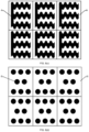
- the hydrophilic-material surfaces 31 and hydrophobic-material surfaces 32 are alternately distributed on the outer surface of each hydrophilic and hydrophobic sheet, which is as shown in FIGS. 8(a) to 8(g) .
- connection means such as bonding, rivets, threads, micro-welding, the hydrophilic and hydrophobic sheets may be directly attached to or mounted on the surface of the inner wall of the drum body 1 and/or the surface of the stirring structure 2.
- the alternate hydrophilic and hydrophobic surface structure 3 assembled in a modularized manner may be formed on the surface of the inner wall of the drum body 1 and/or the surface of the stirring structure 2, so as to improve mechanical properties of the surface of the inner wall of the drum body 1 and/or the surface of the stirring structure 2, thereby optimizing movement of the leather on the surface of the inner wall of the drum body 1 and/or the surface of the stirring structure 2 in the leather-manufacturing rotary drum and enhancing flow of the bath liquid.
- Advantages of this embodiment lie in that a sheet processing process can be directly carried out on a plane, such that technical problems caused by processing a curved surface are avoided.
- the modularized hydrophilic and hydrophobic sheets are replaceable, such that the cost is lower, and a long-time gain effect of the leather-manufacturing rotary drum in a leather manufacturing process is guaranteed.
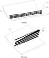
- a schematic structural diagram of modularized hydrophilic and hydrophobic sheets arranged on a surface of a protruding pile 22 is as shown in FIG. 9(a)
- a schematic structural diagram of modularized hydrophilic and hydrophobic sheets arranged on a surface of a baffle 21 is as shown in FIG. 9(b) .
- a method for preparing a hydrophilic and hydrophobic sheet is as follows: in a high-temperature and high-pressure environment, a hydrophobic sheet in a special shape obtained by linear cutting is embedded on a surface of hydrophilic resin, then a surface of the hydrophobic sheet is corroded by a CuCI2 solution, and the surface of the sheet is modified by a constant-temperature water bath of an absolute ethyl alcohol solution with stearic acid, so as to finally obtain a composite surface with a hydrophilic region and a hydrophobic region coexisting, that is, the hydrophilic and hydrophobic sheet in this embodiment.
- the alternate hydrophilic and hydrophobic surface structure 3 is a structure in which modularized hydrophilic sheets and hydrophobic coatings are alternately distributed. Outer surfaces of the hydrophilic sheets are the hydrophilic-material surfaces 31, and the hydrophilic sheets are mounted in close contact with the surface of the inner wall of the drum body 1 and/or the surface of the stirring structure 2; and the hydrophobic coatings are the hydrophobic-material surfaces 32 and are formed by preparing hydrophobic materials on the surface of the inner wall of the drum body 1 and/or the surface of the stirring structure 2.
- the hydrophilic-material surfaces 31 are mounted on the surface of the inner wall of the drum body 1 and/or the surface of the stirring structure 2 in the form of hydrophilic sheets, and the hydrophobic-material surfaces 32 are presented as hydrophobic coatings.
- surface characteristics of the material of the inner wall of the drum body 1 and/or the material of the stirring structure 2 are changed, thereby optimizing movement of the leather on the surface of the inner wall of the drum body 1 and/or the surface of the stirring structure 2 in the leather-manufacturing rotary drum, enhancing flow of the bath liquid, and realizing a physical mechanism, principle and method for enhancing a mechanical action in a leather manufacturing process by means of the hydrophilic sheets and the hydrophobic coatings that are alternately arranged.
- a representation form of an alternate hydrophilic and hydrophobic surface structure 3 is provided.
- the alternate hydrophilic and hydrophobic surface structure 3 is a structure in which modularized hydrophilic sheets and polished original surfaces of the inner wall of the drum body 1 and/or the stirring structure 2 are alternately distributed. Outer surfaces of the hydrophilic sheets are the hydrophilic-material surfaces 31, and the hydrophilic sheets are mounted in close contact with the surface of the inner wall of the drum body 1 and/or the surface of the stirring structure 2; and the polished original surfaces of the inner wall of the drum body 1 and/or the stirring structure 2 are the hydrophobic-material surfaces 32.
- the hydrophilic-material surfaces 31 are mounted on the surface of the inner wall of the drum body 1 and/or the surface of the stirring structure 2 in the form of hydrophilic sheets, and the hydrophobic-material surfaces 32 are presented as the polished original surfaces of the inner wall of the drum body 1 and/or the surface of the stirring structure 2.
- the hydrophilic sheets may be understood as sheet structures only with hydrophilic-material surfaces 31, and the hydrophilic-material surfaces 31 on the sheet structures may be prepared in the form of coatings.
- the hydrophilic sheets may be mounted on the surface of the inner wall of the drum body 1 and/or the surface of the stirring structure 2 through connection means such as bonding, rivets, threads, micro-welding, and the hydrophilic sheets and the hydrophobic-material surfaces 32 are alternately arranged.
- the alternate hydrophilic and hydrophobic surface structure 3 is a structure in which hydrophilic coatings and modularized hydrophobic sheets are alternately distributed.
- the hydrophilic coatings are the hydrophilic-material surfaces 31 and are formed by preparing hydrophilic materials on the surface of the inner wall of the drum body 1 and/or the surface of the stirring structure 2; and outer surfaces of the hydrophobic sheets are the hydrophobic-material surfaces 32, and the hydrophobic sheets are mounted in close contact with the surface of the inner wall of the drum body 1 and/or the surface of the stirring structure 2.
- the hydrophobic-material surfaces 32 are mounted on the surface of the inner wall of the drum body 1 and/or the surface of the stirring structure 2 in the form of hydrophobic sheets, and the hydrophilic-material surfaces 31 are presented in the form of hydrophilic coatings.
- the hydrophobic sheets in this embodiment may be understood as sheet structures only with hydrophobic-material surfaces 32, and the hydrophobic-material surfaces 32 on the sheet structures may be prepared in the form of coatings.
- the hydrophobic sheets may be mounted on the surface of the inner wall of the drum body 1 and/or the surface of the stirring structure 2 through connection means such as bonding, rivets, threads, micro-welding, and the hydrophobic sheets and the hydrophilic coatings are alternately arranged.
- connection means such as bonding, rivets, threads, micro-welding
- the alternate hydrophilic and hydrophobic surface structure 3 is a structure in which modularized hydrophilic sheets and modularized hydrophobic sheets are alternately distributed. Outer surfaces of the hydrophilic sheets are the hydrophilic-material surfaces 31, and the hydrophilic sheets are mounted in close contact with the surface of the inner wall of the drum body 1 and/or the surface of the stirring structure 2; and outer surfaces of the hydrophobic sheets are the hydrophobic-material surfaces 32, and the hydrophobic sheets are mounted in close contact with the surface of the inner wall of the drum body 1 and/or the surface of the stirring structure 2.
- the hydrophilic-material surfaces 31 are mounted on the surface of the inner wall of the drum body 1 and/or the surface of the stirring structure 2 in the form of hydrophilic sheets
- the hydrophobic-material surfaces 32 are mounted on the surface of the inner wall of the drum body 1 and/or the surface of the stirring structure 2 in the form of hydrophobic sheets.
- the hydrophilic sheets in the embodiment may be understood as sheet structures only with hydrophilic-material surfaces 31, and the hydrophilic-material surfaces 31 on the sheet structures may be prepared in the form of coatings.
- the hydrophobic sheets in this embodiment may be understood as sheet structures only with hydrophobic-material surfaces 32, and the hydrophobic-material surfaces 32 on the sheet structures may be prepared in the form of coatings.
- the hydrophilic sheets and the hydrophobic sheets may be both mounted on the surface of the inner wall of the drum body 1 and/or the surface of the stirring structure 2 through connection means such as bonding, rivets, threads, micro-welding, and the hydrophilic sheets and the hydrophobic sheets are assembled with each other, thereby forming the alternate hydrophilic and hydrophobic surface structure 3 on the surface of the inner wall of the drum body 1 and/or the surface of the stirring structure 2.
- shapes of the hydrophilic-material surfaces 31 and the hydrophobic-material surfaces 32 are not limited in the present invention, which may be in a straight-line shape, a triangular shape, a zigzag shape or a wavy shape, or may be distributed in the form of spots, and the spot shape may include a circular shape, a triangular shape, a rectangular shape, a polygonal shape, or any other shape.
- the presentation of the hydrophilic-material surfaces 31 and the hydrophobic-material surfaces 32 that are alternately distributed on outer surfaces of the hydrophilic and hydrophobic sheets in different patterns and shapes may be as shown in FIGS.
- FIGS. 10(a) to 10(g) the presentation of the hydrophilic coatings and the hydrophobic coatings that are alternately distributed on the surface of the baffle 21 in different patterns and shapes may be as shown in FIGS. 10(a) to 10(g) .
- the hydrophilic-material surfaces 31 and the hydrophobic-material surfaces 32 are both in straight-line shapes.
- the reason why the hydrophilic-material surfaces 31 and the hydrophobic-material surfaces 32 are preferably in straight-line shapes is that the processing difficulty of a straight-line shape is low, and the hydrophilic-material surfaces 31 and the hydrophobic-material surfaces 32 can obtain a better area ratio, which is beneficial to implementation of the solution of the present invention.
- FIG. 1 for the leather-manufacturing rotary drum, two drum base plates 10 are mounted on two sides of a drum body 1 by means of drum hoops 4, four connecting retaining rings 5 distributed at 90 degrees are welded to the drum hoops 4, and each connecting retaining ring 5 is provided with two screw holes connected to the drum body 1, with the aim of enable sealing rings between the drum base plates 10 and the drum body 1 to achieve a sealing function.
- each drum base plate 10 is provided with a reinforced base plate 9 by means of screws, reinforced ribs are distributed on the reinforced base plate 9 at intervals of 60 degrees, and each reinforced rib is provided with three screw holes, so as to provide a radial acting force on the drum base plate 10, such that the drum base plate 10 is more tightly sealed against the drum body 1.
- a drum main shaft 8 is connected to the drum base plates 10 in a welded manner, and is nested with the reinforced base plates 9 by means of keys.
- the drum main shaft is connected to a bearing 7 on a supporting frame 6, and the drum main shaft and the bearing are mounted on a positioning support together.
- a drum door 11 is further arranged on a side surface of the drum body 1, and sliding rails are arranged on two sides of the drum door 11 so as to facilitate opening or closing the door when leather is added.
- the drum body 1 mainly comprises protruding piles 22, baffles 21 and an alternate hydrophilic and hydrophobic surface structure 3. Hydrophilic-material surfaces 31 and hydrophobic-material surfaces 32 of the alternate hydrophilic and hydrophobic surface structure 3 are distributed on surfaces of the protruding piles 22 and the baffles 21 in a stripe shape, as shown in FIGS. 1, 2 , and 5 to 7 .
- a first physical phenomenon is that when the protruding piles 22 or the baffles 21 draw the leather into the bath liquid, under the action of the strong drawing force of the alternate hydrophilic and hydrophobic surface structure 3, the leather is not likely to fall off, and the bath liquid at a bottom is more easy to stir, such that a flow field becomes disordered, and a mass transfer action is enhanced.
- a second physical phenomenon is that when the leather is drawn away from the bath liquid by the protruding piles 22 or the baffles 21, due to a strong adhesive force of the hydrophilic-material surfaces 31 to droplets, a large number of droplets will be adhered to the hydrophilic-material surfaces 31.
- a mass transfer action will occur between the leather and the bath liquid adhered to the alternate hydrophilic and hydrophobic surface structure, such that relative leather manufacturing time is prolonged.
- a third physical phenomenon is that under the action of a strong drawing force of the alternate hydrophilic and hydrophobic surface structure 3, the lifting leather can move to a higher drawing position, such that extension is more sufficient; moreover, throwing kinetic energy is increased in a falling process. Therefore, the alternate hydrophilic and hydrophobic surface structure 3 can achieve gain effects, and in an actual leather manufacturing process, not only can a mass transfer effect of leather be improved and leather manufacturing time be shortened, but an adverse effect of a long-time mechanical action on physical and mechanical properties of the leather can also be avoided.
- a distribution angle of the baffles 21 and the protruding piles 22 in a circumferential direction is 30 degrees.
- the arrangement mode of two adjacent protruding piles 22 in a direction of the drum body 1 is a staggered arrangement, with the aim of destroying a fixed form of the leather in the rotary drum, thereby enhancing a mechanical action and improving a leather manufacturing effect.
- Strip-type hydrophilic sheets are formed on the surfaces of the baffles 21 and the protruding piles 22, and original surfaces of the baffles and the protruding piles serve as hydrophobic-material surfaces 32, thereby achieving the function of an alternate hydrophilic and hydrophobic surface.
- Chemically treated gold coatings may be used as outer surfaces of the hydrophilic sheets, and the hydrophilic-material surfaces 31 are preferably in a straight-line shape, so as to enhance a leather manufacturing process at a low cost.
- an orientation or positional relationship indicated by terms “center”, “upper”, “lower”, “left”, “right”, “vertical”, “horizontal”, “inner”, “outer”, etc. is an orientation or positional relationship shown on the basis of the accompanying drawings, which is only for convenience of describing the present invention and simplifying the description, rather than indicating or implying that the referred device or element must have a particular orientation, and be constructed and operated in a particular orientation, and therefore should not be construed as limiting the present invention.
- relational terms such as “first” and “second” are merely used to distinguish one entity or operation from another entity or operation, do not necessarily require or imply that any actual relation or sequence exists between these entities or operations, and should not be constructed as indicating or implying relative importance.
- terms “include”, “comprise”, or any other variants thereof are intended to cover a non-exclusive inclusion, such that a process, method, article, or terminal apparatus that includes a list of elements not only includes those elements but also includes other elements that are not listed, or further includes elements inherent to such a process, method, article, or terminal apparatus. In the absence of more restrictions, an element defined by “including a" does not exclude a further identical element in a process, method, article, or terminal apparatus that includes the element.
Landscapes
- Chemical & Material Sciences (AREA)
- Chemical Kinetics & Catalysis (AREA)
- General Chemical & Material Sciences (AREA)
- Organic Chemistry (AREA)
- Treatment And Processing Of Natural Fur Or Leather (AREA)
Claims (10)
- Drehtrommel für die Lederherstellung, die eine abwechselnd hydrophile und hydrophobe Oberflächenstruktur (3) aufweist, dadurch gekennzeichnet, dass sie umfasst:einen Trommelkörper (1), der in der Lage ist, in seiner eigenen Umfangsrichtung zu drehen;eine Rührstruktur (2), die im Trommelkörper (1) eingerichtet ist; undeine abwechselnd hydrophile und hydrophobe Oberflächenstruktur (3), bei der Oberflächen aus hydrophilem Material (31) und Oberflächen aus hydrophobem Material (32) abwechselnd verteilt sind, wobei die abwechselnd hydrophile und hydrophobe Oberflächenstruktur (3) auf einer Oberfläche einer Innenwand des Trommelkörpers (1) und/oder einer Oberfläche der Rührstruktur (2) verteilt ist,wobei bei einem Drehprozess des Trommelkörpers (1) die abwechselnd hydrophile und hydrophobe Oberflächenstruktur (3) wiederholt in eine Badflüssigkeit im Trommelkörper (1) eintritt und diese verlässt.
- Drehtrommel für die Lederherstellung nach Anspruch 1, dadurch gekennzeichnet, dass die abwechselnd hydrophile und hydrophobe Oberflächenstruktur (3) eine Struktur ist, bei der hydrophile Beschichtungen und hydrophobe Beschichtungen abwechselnd verteilt sind, wobei:die hydrophilen Beschichtungen die Oberflächen aus hydrophilem Material (31) sind und durch Anfertigen von hydrophilen Materialien auf der Oberfläche der Innenwand des Trommelkörpers (1) und/oder der Oberfläche der Rührstruktur (2) gebildet sind; unddie hydrophoben Beschichtungen die Oberflächen aus hydrophobem Material (32) sind und durch Anfertigen von hydrophoben Materialien auf der Oberfläche der Innenwand des Trommelkörpers (1) und/oder der Oberfläche der Rührstruktur (2) gebildet sind.
- Drehtrommel für die Lederherstellung nach Anspruch 1, dadurch gekennzeichnet, dass die abwechselnd hydrophile und hydrophobe Oberflächenstruktur (3) eine Struktur ist, bei der hydrophile Beschichtungen und polierte ursprüngliche Oberflächen der Innenwand des Trommelkörpers (1) und/oder der Rührstruktur (2) abwechselnd verteilt sind, wobei:die hydrophilen Beschichtungen die Oberflächen aus hydrophilem Material (31) sind und durch Anfertigen von hydrophilen Materialien auf der Oberfläche der Innenwand des Trommelkörpers (1) und/oder der Oberfläche der Rührstruktur (2) gebildet sind; unddie polierten ursprünglichen Oberflächen der Innenwand des Trommelkörpers (1) und/oder der Rührstruktur (2) die Oberflächen aus hydrophobem Material (32) sind.
- Drehtrommel für die Lederherstellung nach Anspruch 1, dadurch gekennzeichnet, dass die abwechselnd hydrophile und hydrophobe Oberflächenstruktur (3) eine Struktur ist, die durch Zusammensetzen einer Vielzahl von modularisierten hydrophilen und hydrophoben Lagen gebildet ist, wobei:
Außenoberflächen der hydrophilen und hydrophoben Lagen abwechselnd verteilte Oberflächen der Oberflächen aus hydrophilem Material (31) und der Oberflächen aus hydrophobem Material (32) sind, und die hydrophilen und hydrophoben Lagen in engem Kontakt mit der Oberfläche der Innenwand des Trommelkörpers (1) und/oder der Oberfläche der Rührstruktur (2) angebracht sind. - Drehtrommel für die Lederherstellung nach Anspruch 1, dadurch gekennzeichnet, dass die abwechselnd hydrophile und hydrophobe Oberflächenstruktur (3) eine Struktur ist, bei der modularisierte hydrophile Lagen und hydrophobe Beschichtungen abwechselnd verteilt sind, wobei:Außenoberflächen der hydrophilen Lagen die Oberflächen aus hydrophilem Material (31) sind, und die hydrophilen Lagen in engem Kontakt mit der Oberfläche der Innenwand des Trommelkörpers (1) und/oder der Oberfläche der Rührstruktur (2) angebracht sind; unddie hydrophoben Beschichtungen die Oberflächen aus hydrophobem Material (32) sind und durch Anfertigen von hydrophoben Materialien auf der Oberfläche der Innenwand des Trommelkörpers (1) und/oder der Oberfläche der Rührstruktur (2) gebildet sind.
- Drehtrommel für die Lederherstellung nach Anspruch 1, dadurch gekennzeichnet, dass die abwechselnd hydrophile und hydrophobe Oberflächenstruktur (3) eine Struktur ist, bei der modularisierte hydrophile Lagen und polierte ursprüngliche Oberflächen der Innenwand des Trommelkörpers (1) und/oder der Rührstruktur (2) abwechselnd verteilt sind, wobei:Außenoberflächen der hydrophilen Lagen die Oberflächen aus hydrophilem Material (31) sind, und die hydrophilen Lagen in engem Kontakt mit der Oberfläche der Innenwand des Trommelkörpers (1) und/oder der Oberfläche der Rührstruktur (2) angebracht sind; unddie polierten ursprünglichen Oberflächen der Innenwand des Trommelkörpers (1) und/oder der Rührstruktur (2) die Oberflächen aus hydrophobem Material (32) sind.
- Drehtrommel für die Lederherstellung nach Anspruch 1, dadurch gekennzeichnet, dass die abwechselnd hydrophile und hydrophobe Oberflächenstruktur (3) eine Struktur ist, bei der hydrophile Beschichtungen und modularisierte hydrophobe Lagen abwechselnd verteilt sind, wobei:die hydrophilen Beschichtungen die Oberflächen aus hydrophilem Material (31) sind und durch Anfertigen von hydrophilen Materialien auf der Oberfläche der Innenwand des Trommelkörpers (1) und/oder der Oberfläche der Rührstruktur (2) gebildet sind; undAußenoberflächen der hydrophoben Lagen die Oberflächen aus hydrophobem Material (32) sind, und die hydrophoben Lagen in engem Kontakt mit der Oberfläche der Innenwand des Trommelkörpers (1) und/oder der Oberfläche der Rührstruktur (2) angebracht sind.
- Drehtrommel für die Lederherstellung nach Anspruch 1, dadurch gekennzeichnet, dass die abwechselnd hydrophile und hydrophobe Oberflächenstruktur (3) eine Struktur ist, bei der modularisierte hydrophile Lagen und modularisierte hydrophobe Lagen abwechselnd verteilt sind, wobei:Außenoberflächen der hydrophilen Lagen die Oberflächen aus hydrophilem Material (31) sind, und die hydrophilen Lagen in engem Kontakt mit der Oberfläche der Innenwand des Trommelkörpers (1) und/oder der Oberfläche der Rührstruktur (2) angebracht sind; undAußenoberflächen der hydrophoben Lagen die Oberflächen aus hydrophobem Material (32) sind, und die hydrophoben Lagen in engem Kontakt mit der Oberfläche der Innenwand des Trommelkörpers (1) und/oder der Oberfläche der Rührstruktur (2) angebracht sind.
- Drehtrommel für die Lederherstellung nach einem der Ansprüche 1-8, dadurch gekennzeichnet, dass die Rührstruktur (2) Leitbleche (21) und/oder vorspringende Stapel (22) umfasst, und beim Drehprozess des Trommelkörpers (1) die Leitbleche (21) und/oder die vorspringenden Stapel (22) wiederholt in die Badflüssigkeit im Trommelkörper (1) eintreten und diese verlassen.
- Drehtrommel für die Lederherstellung nach Anspruch 9, dadurch gekennzeichnet, dass, wenn die Rührstruktur (2) sowohl die Leitbleche (21) als auch die vorspringenden Stapel (22) umfasst, die Leitbleche (21) und die vorspringenden Stapel (22) abwechselnd entlang einer Umfangswandoberfläche des Trommelkörpers (1) verteilt sind.
Applications Claiming Priority (2)
| Application Number | Priority Date | Filing Date | Title |
|---|---|---|---|
| CN202110764267.8A CN113512612B (zh) | 2021-07-06 | 2021-07-06 | 一种具有亲疏水间隔表面结构的制革转鼓 |
| PCT/CN2022/092096 WO2023279842A1 (zh) | 2021-07-06 | 2022-05-11 | 一种具有亲疏水间隔表面结构的制革转鼓 |
Publications (3)
| Publication Number | Publication Date |
|---|---|
| EP4137589A1 EP4137589A1 (de) | 2023-02-22 |
| EP4137589A4 EP4137589A4 (de) | 2023-09-06 |
| EP4137589B1 true EP4137589B1 (de) | 2024-04-03 |
Family
ID=78066804
Family Applications (1)
| Application Number | Title | Priority Date | Filing Date |
|---|---|---|---|
| EP22768604.5A Active EP4137589B1 (de) | 2021-07-06 | 2022-05-11 | Gerbtrommel mit einer struktur mit voneinander beabstandeten hydrophilen und hydrophoben oberflächen |
Country Status (3)
| Country | Link |
|---|---|
| EP (1) | EP4137589B1 (de) |
| CN (1) | CN113512612B (de) |
| WO (1) | WO2023279842A1 (de) |
Families Citing this family (2)
| Publication number | Priority date | Publication date | Assignee | Title |
|---|---|---|---|---|
| CN113512612B (zh) * | 2021-07-06 | 2022-02-18 | 四川大学 | 一种具有亲疏水间隔表面结构的制革转鼓 |
| IT202300001344A1 (it) * | 2023-01-27 | 2024-07-27 | Officina Bartaloni S R L | Struttura di bottale per concerie |
Family Cites Families (13)
| Publication number | Priority date | Publication date | Assignee | Title |
|---|---|---|---|---|
| SU1642756A1 (ru) * | 1989-05-22 | 1995-10-10 | Восточно-Сибирский технологический институт | Линия для обработки кожевенного полуфабриката |
| RU2090620C1 (ru) * | 1993-03-22 | 1997-09-20 | Восточно-Сибирский государственный технологический университет | Линия для обработки меховых шкур |
| UY3911U (es) * | 2002-07-25 | 2003-12-31 | Ricardo Antonio Tournier Docam | Mejoras en fulones para el tratamiento de pieles, cueros o similares |
| CN102115797B (zh) * | 2010-11-25 | 2013-08-28 | 浙江中辉皮草有限公司 | 木转鼓结构 |
| WO2013060602A2 (en) * | 2011-10-24 | 2013-05-02 | BSH Bosch und Siemens Hausgeräte GmbH | A washing machine having a component |
| JP6411724B2 (ja) * | 2013-10-23 | 2018-10-24 | 東芝ライフスタイル株式会社 | 洗濯機 |
| CN204702765U (zh) * | 2015-04-30 | 2015-10-14 | 长兴远华皮革机械有限公司 | 一种木质皮革转鼓 |
| US10351247B2 (en) * | 2015-06-15 | 2019-07-16 | Subaru Corporation | Wing and anti-icing system |
| CN106243374A (zh) * | 2016-08-19 | 2016-12-21 | 无锡市新达轻工机械有限公司 | 聚丙烯转鼓及其制备工艺 |
| CN207987272U (zh) * | 2018-01-15 | 2018-10-19 | 晋江源泰皮革有限公司 | 一种用于皮革生产的转鼓的溶液内循环装置 |
| CN109469580B (zh) * | 2018-09-25 | 2023-09-29 | 天津瑞能电气有限公司 | 一种超疏水亲水间隔涂覆控冰叶片及方法 |
| CN211999784U (zh) * | 2020-04-27 | 2020-11-24 | 项城市双强皮业有限公司 | 一种基于plc控制的羊剪绒皮料鞣制转鼓 |
| CN113512612B (zh) * | 2021-07-06 | 2022-02-18 | 四川大学 | 一种具有亲疏水间隔表面结构的制革转鼓 |
-
2021
- 2021-07-06 CN CN202110764267.8A patent/CN113512612B/zh active Active
-
2022
- 2022-05-11 WO PCT/CN2022/092096 patent/WO2023279842A1/zh not_active Ceased
- 2022-05-11 EP EP22768604.5A patent/EP4137589B1/de active Active
Also Published As
| Publication number | Publication date |
|---|---|
| CN113512612A (zh) | 2021-10-19 |
| CN113512612B (zh) | 2022-02-18 |
| EP4137589A1 (de) | 2023-02-22 |
| EP4137589A4 (de) | 2023-09-06 |
| WO2023279842A1 (zh) | 2023-01-12 |
Similar Documents
| Publication | Publication Date | Title |
|---|---|---|
| EP4137589B1 (de) | Gerbtrommel mit einer struktur mit voneinander beabstandeten hydrophilen und hydrophoben oberflächen | |
| JP6185187B2 (ja) | 感光性樹脂組成物、平版印刷版原版、平版印刷版の作製方法、及び、高分子化合物 | |
| ES2139187T3 (es) | Material compuesto microporoso de polimero perfluorado intercambiador de iones y de oxido metalico obtenido por un sol-gel. | |
| CN101568726B (zh) | 斜板式活塞泵·马达及其制造方法 | |
| JP2019048255A (ja) | 金属切削屑の洗浄方法および洗浄装置 | |
| TW201610260A (zh) | 洗衣機及洗衣機的製造方法 | |
| CN206752139U (zh) | 一种压式洗衣机 | |
| CN113913892A (zh) | 一种可变阴极面积的微弧氧化装置及表面处理方法 | |
| CN115365987A (zh) | 一种物理与化学同时抛光工件的工艺与应用 | |
| CN210560833U (zh) | 封闭式电泳漆表面气泡处理装置 | |
| CN104107979B (zh) | 轧辊表面激光毛化强化集成加工装置 | |
| CN109096876A (zh) | 一种石墨烯防腐剂及安装支架的防腐方法 | |
| CN111873171A (zh) | 一种电线杆混凝土加工用蒸养设备 | |
| CN216857128U (zh) | 一种用于金属热处理用涂抹装置 | |
| CN108869279A (zh) | 泵体组件、流体机械及换热设备 | |
| CN107879458A (zh) | 一种工业废液处理装置 | |
| CN114247487A (zh) | 一种液位控制的旋转阳极氧化装置及氧化方法 | |
| CN209302721U (zh) | 一种适用于重铬酸钠液相反应釜中的搅拌桨叶 | |
| CN208578715U (zh) | 泵体组件、流体机械及换热设备 | |
| CN110976684B (zh) | 双层烙锅的手工旋压加工方法 | |
| CN208018485U (zh) | 一种多轴驱动涂料搅拌机 | |
| CN214440257U (zh) | 一种钢构件喷漆装置 | |
| RU2799180C1 (ru) | Способ сухого электрополирования лопатки турбомашины и установка для его реализации | |
| CN217052469U (zh) | 一种垂直连续电镀设备 | |
| CN112456577B (zh) | 一种油漆废渣污水处理一体机 |
Legal Events
| Date | Code | Title | Description |
|---|---|---|---|
| STAA | Information on the status of an ep patent application or granted ep patent |
Free format text: STATUS: UNKNOWN |
|
| STAA | Information on the status of an ep patent application or granted ep patent |
Free format text: STATUS: THE INTERNATIONAL PUBLICATION HAS BEEN MADE |
|
| PUAI | Public reference made under article 153(3) epc to a published international application that has entered the european phase |
Free format text: ORIGINAL CODE: 0009012 |
|
| STAA | Information on the status of an ep patent application or granted ep patent |
Free format text: STATUS: REQUEST FOR EXAMINATION WAS MADE |
|
| 17P | Request for examination filed |
Effective date: 20220920 |
|
| AK | Designated contracting states |
Kind code of ref document: A1 Designated state(s): AL AT BE BG CH CY CZ DE DK EE ES FI FR GB GR HR HU IE IS IT LI LT LU LV MC MK MT NL NO PL PT RO RS SE SI SK SM TR |
|
| STAA | Information on the status of an ep patent application or granted ep patent |
Free format text: STATUS: EXAMINATION IS IN PROGRESS |
|
| A4 | Supplementary search report drawn up and despatched |
Effective date: 20230807 |
|
| RIC1 | Information provided on ipc code assigned before grant |
Ipc: B01F 29/63 20220101ALI20230731BHEP Ipc: B01F 29/00 20220101ALI20230731BHEP Ipc: C14C 15/00 20060101AFI20230731BHEP |
|
| 17Q | First examination report despatched |
Effective date: 20230822 |
|
| GRAP | Despatch of communication of intention to grant a patent |
Free format text: ORIGINAL CODE: EPIDOSNIGR1 |
|
| STAA | Information on the status of an ep patent application or granted ep patent |
Free format text: STATUS: GRANT OF PATENT IS INTENDED |
|
| INTG | Intention to grant announced |
Effective date: 20240119 |
|
| GRAS | Grant fee paid |
Free format text: ORIGINAL CODE: EPIDOSNIGR3 |
|
| GRAA | (expected) grant |
Free format text: ORIGINAL CODE: 0009210 |
|
| STAA | Information on the status of an ep patent application or granted ep patent |
Free format text: STATUS: THE PATENT HAS BEEN GRANTED |
|
| AK | Designated contracting states |
Kind code of ref document: B1 Designated state(s): AL AT BE BG CH CY CZ DE DK EE ES FI FR GB GR HR HU IE IS IT LI LT LU LV MC MK MT NL NO PL PT RO RS SE SI SK SM TR |
|
| DAV | Request for validation of the european patent (deleted) | ||
| DAX | Request for extension of the european patent (deleted) | ||
| REG | Reference to a national code |
Ref country code: CH Ref legal event code: EP |
|
| REG | Reference to a national code |
Ref country code: IE Ref legal event code: FG4D |
|
| REG | Reference to a national code |
Ref country code: DE Ref legal event code: R096 Ref document number: 602022002724 Country of ref document: DE |
|
| REG | Reference to a national code |
Ref country code: LT Ref legal event code: MG9D |
|
| REG | Reference to a national code |
Ref country code: NL Ref legal event code: MP Effective date: 20240403 |
|
| REG | Reference to a national code |
Ref country code: AT Ref legal event code: MK05 Ref document number: 1672368 Country of ref document: AT Kind code of ref document: T Effective date: 20240403 |
|
| PG25 | Lapsed in a contracting state [announced via postgrant information from national office to epo] |
Ref country code: NL Free format text: LAPSE BECAUSE OF FAILURE TO SUBMIT A TRANSLATION OF THE DESCRIPTION OR TO PAY THE FEE WITHIN THE PRESCRIBED TIME-LIMIT Effective date: 20240403 |
|
| PG25 | Lapsed in a contracting state [announced via postgrant information from national office to epo] |
Ref country code: NL Free format text: LAPSE BECAUSE OF FAILURE TO SUBMIT A TRANSLATION OF THE DESCRIPTION OR TO PAY THE FEE WITHIN THE PRESCRIBED TIME-LIMIT Effective date: 20240403 |
|
| PG25 | Lapsed in a contracting state [announced via postgrant information from national office to epo] |
Ref country code: IS Free format text: LAPSE BECAUSE OF FAILURE TO SUBMIT A TRANSLATION OF THE DESCRIPTION OR TO PAY THE FEE WITHIN THE PRESCRIBED TIME-LIMIT Effective date: 20240803 |
|
| PG25 | Lapsed in a contracting state [announced via postgrant information from national office to epo] |
Ref country code: BG Free format text: LAPSE BECAUSE OF FAILURE TO SUBMIT A TRANSLATION OF THE DESCRIPTION OR TO PAY THE FEE WITHIN THE PRESCRIBED TIME-LIMIT Effective date: 20240403 |
|
| PG25 | Lapsed in a contracting state [announced via postgrant information from national office to epo] |
Ref country code: HR Free format text: LAPSE BECAUSE OF FAILURE TO SUBMIT A TRANSLATION OF THE DESCRIPTION OR TO PAY THE FEE WITHIN THE PRESCRIBED TIME-LIMIT Effective date: 20240403 Ref country code: FI Free format text: LAPSE BECAUSE OF FAILURE TO SUBMIT A TRANSLATION OF THE DESCRIPTION OR TO PAY THE FEE WITHIN THE PRESCRIBED TIME-LIMIT Effective date: 20240403 |
|
| PG25 | Lapsed in a contracting state [announced via postgrant information from national office to epo] |
Ref country code: GR Free format text: LAPSE BECAUSE OF FAILURE TO SUBMIT A TRANSLATION OF THE DESCRIPTION OR TO PAY THE FEE WITHIN THE PRESCRIBED TIME-LIMIT Effective date: 20240704 |
|
| PG25 | Lapsed in a contracting state [announced via postgrant information from national office to epo] |
Ref country code: PT Free format text: LAPSE BECAUSE OF FAILURE TO SUBMIT A TRANSLATION OF THE DESCRIPTION OR TO PAY THE FEE WITHIN THE PRESCRIBED TIME-LIMIT Effective date: 20240805 |
|
| PG25 | Lapsed in a contracting state [announced via postgrant information from national office to epo] |
Ref country code: ES Free format text: LAPSE BECAUSE OF FAILURE TO SUBMIT A TRANSLATION OF THE DESCRIPTION OR TO PAY THE FEE WITHIN THE PRESCRIBED TIME-LIMIT Effective date: 20240403 |
|
| PG25 | Lapsed in a contracting state [announced via postgrant information from national office to epo] |
Ref country code: CZ Free format text: LAPSE BECAUSE OF FAILURE TO SUBMIT A TRANSLATION OF THE DESCRIPTION OR TO PAY THE FEE WITHIN THE PRESCRIBED TIME-LIMIT Effective date: 20240403 |
|
| PG25 | Lapsed in a contracting state [announced via postgrant information from national office to epo] |
Ref country code: AT Free format text: LAPSE BECAUSE OF FAILURE TO SUBMIT A TRANSLATION OF THE DESCRIPTION OR TO PAY THE FEE WITHIN THE PRESCRIBED TIME-LIMIT Effective date: 20240403 |
|
| PG25 | Lapsed in a contracting state [announced via postgrant information from national office to epo] |
Ref country code: PL Free format text: LAPSE BECAUSE OF FAILURE TO SUBMIT A TRANSLATION OF THE DESCRIPTION OR TO PAY THE FEE WITHIN THE PRESCRIBED TIME-LIMIT Effective date: 20240403 |
|
| PG25 | Lapsed in a contracting state [announced via postgrant information from national office to epo] |
Ref country code: LV Free format text: LAPSE BECAUSE OF FAILURE TO SUBMIT A TRANSLATION OF THE DESCRIPTION OR TO PAY THE FEE WITHIN THE PRESCRIBED TIME-LIMIT Effective date: 20240403 |
|
| PG25 | Lapsed in a contracting state [announced via postgrant information from national office to epo] |
Ref country code: PT Free format text: LAPSE BECAUSE OF FAILURE TO SUBMIT A TRANSLATION OF THE DESCRIPTION OR TO PAY THE FEE WITHIN THE PRESCRIBED TIME-LIMIT Effective date: 20240805 Ref country code: PL Free format text: LAPSE BECAUSE OF FAILURE TO SUBMIT A TRANSLATION OF THE DESCRIPTION OR TO PAY THE FEE WITHIN THE PRESCRIBED TIME-LIMIT Effective date: 20240403 Ref country code: NO Free format text: LAPSE BECAUSE OF FAILURE TO SUBMIT A TRANSLATION OF THE DESCRIPTION OR TO PAY THE FEE WITHIN THE PRESCRIBED TIME-LIMIT Effective date: 20240703 Ref country code: LV Free format text: LAPSE BECAUSE OF FAILURE TO SUBMIT A TRANSLATION OF THE DESCRIPTION OR TO PAY THE FEE WITHIN THE PRESCRIBED TIME-LIMIT Effective date: 20240403 Ref country code: IS Free format text: LAPSE BECAUSE OF FAILURE TO SUBMIT A TRANSLATION OF THE DESCRIPTION OR TO PAY THE FEE WITHIN THE PRESCRIBED TIME-LIMIT Effective date: 20240803 Ref country code: HR Free format text: LAPSE BECAUSE OF FAILURE TO SUBMIT A TRANSLATION OF THE DESCRIPTION OR TO PAY THE FEE WITHIN THE PRESCRIBED TIME-LIMIT Effective date: 20240403 Ref country code: GR Free format text: LAPSE BECAUSE OF FAILURE TO SUBMIT A TRANSLATION OF THE DESCRIPTION OR TO PAY THE FEE WITHIN THE PRESCRIBED TIME-LIMIT Effective date: 20240704 Ref country code: FI Free format text: LAPSE BECAUSE OF FAILURE TO SUBMIT A TRANSLATION OF THE DESCRIPTION OR TO PAY THE FEE WITHIN THE PRESCRIBED TIME-LIMIT Effective date: 20240403 Ref country code: ES Free format text: LAPSE BECAUSE OF FAILURE TO SUBMIT A TRANSLATION OF THE DESCRIPTION OR TO PAY THE FEE WITHIN THE PRESCRIBED TIME-LIMIT Effective date: 20240403 Ref country code: CZ Free format text: LAPSE BECAUSE OF FAILURE TO SUBMIT A TRANSLATION OF THE DESCRIPTION OR TO PAY THE FEE WITHIN THE PRESCRIBED TIME-LIMIT Effective date: 20240403 Ref country code: BG Free format text: LAPSE BECAUSE OF FAILURE TO SUBMIT A TRANSLATION OF THE DESCRIPTION OR TO PAY THE FEE WITHIN THE PRESCRIBED TIME-LIMIT Effective date: 20240403 Ref country code: AT Free format text: LAPSE BECAUSE OF FAILURE TO SUBMIT A TRANSLATION OF THE DESCRIPTION OR TO PAY THE FEE WITHIN THE PRESCRIBED TIME-LIMIT Effective date: 20240403 Ref country code: RS Free format text: LAPSE BECAUSE OF FAILURE TO SUBMIT A TRANSLATION OF THE DESCRIPTION OR TO PAY THE FEE WITHIN THE PRESCRIBED TIME-LIMIT Effective date: 20240703 |
|
| REG | Reference to a national code |
Ref country code: DE Ref legal event code: R097 Ref document number: 602022002724 Country of ref document: DE |
|
| PG25 | Lapsed in a contracting state [announced via postgrant information from national office to epo] |
Ref country code: DK Free format text: LAPSE BECAUSE OF FAILURE TO SUBMIT A TRANSLATION OF THE DESCRIPTION OR TO PAY THE FEE WITHIN THE PRESCRIBED TIME-LIMIT Effective date: 20240403 |
|
| PG25 | Lapsed in a contracting state [announced via postgrant information from national office to epo] |
Ref country code: LU Free format text: LAPSE BECAUSE OF NON-PAYMENT OF DUE FEES Effective date: 20240511 |
|
| PG25 | Lapsed in a contracting state [announced via postgrant information from national office to epo] |
Ref country code: EE Free format text: LAPSE BECAUSE OF FAILURE TO SUBMIT A TRANSLATION OF THE DESCRIPTION OR TO PAY THE FEE WITHIN THE PRESCRIBED TIME-LIMIT Effective date: 20240403 |
|
| PG25 | Lapsed in a contracting state [announced via postgrant information from national office to epo] |
Ref country code: SK Free format text: LAPSE BECAUSE OF FAILURE TO SUBMIT A TRANSLATION OF THE DESCRIPTION OR TO PAY THE FEE WITHIN THE PRESCRIBED TIME-LIMIT Effective date: 20240403 Ref country code: RO Free format text: LAPSE BECAUSE OF FAILURE TO SUBMIT A TRANSLATION OF THE DESCRIPTION OR TO PAY THE FEE WITHIN THE PRESCRIBED TIME-LIMIT Effective date: 20240403 |
|
| PG25 | Lapsed in a contracting state [announced via postgrant information from national office to epo] |
Ref country code: SM Free format text: LAPSE BECAUSE OF FAILURE TO SUBMIT A TRANSLATION OF THE DESCRIPTION OR TO PAY THE FEE WITHIN THE PRESCRIBED TIME-LIMIT Effective date: 20240403 |
|
| PG25 | Lapsed in a contracting state [announced via postgrant information from national office to epo] |
Ref country code: SM Free format text: LAPSE BECAUSE OF FAILURE TO SUBMIT A TRANSLATION OF THE DESCRIPTION OR TO PAY THE FEE WITHIN THE PRESCRIBED TIME-LIMIT Effective date: 20240403 Ref country code: SK Free format text: LAPSE BECAUSE OF FAILURE TO SUBMIT A TRANSLATION OF THE DESCRIPTION OR TO PAY THE FEE WITHIN THE PRESCRIBED TIME-LIMIT Effective date: 20240403 Ref country code: RO Free format text: LAPSE BECAUSE OF FAILURE TO SUBMIT A TRANSLATION OF THE DESCRIPTION OR TO PAY THE FEE WITHIN THE PRESCRIBED TIME-LIMIT Effective date: 20240403 Ref country code: LU Free format text: LAPSE BECAUSE OF NON-PAYMENT OF DUE FEES Effective date: 20240511 Ref country code: EE Free format text: LAPSE BECAUSE OF FAILURE TO SUBMIT A TRANSLATION OF THE DESCRIPTION OR TO PAY THE FEE WITHIN THE PRESCRIBED TIME-LIMIT Effective date: 20240403 Ref country code: DK Free format text: LAPSE BECAUSE OF FAILURE TO SUBMIT A TRANSLATION OF THE DESCRIPTION OR TO PAY THE FEE WITHIN THE PRESCRIBED TIME-LIMIT Effective date: 20240403 Ref country code: MC Free format text: LAPSE BECAUSE OF FAILURE TO SUBMIT A TRANSLATION OF THE DESCRIPTION OR TO PAY THE FEE WITHIN THE PRESCRIBED TIME-LIMIT Effective date: 20240403 |
|
| PLBE | No opposition filed within time limit |
Free format text: ORIGINAL CODE: 0009261 |
|
| STAA | Information on the status of an ep patent application or granted ep patent |
Free format text: STATUS: NO OPPOSITION FILED WITHIN TIME LIMIT |
|
| REG | Reference to a national code |
Ref country code: BE Ref legal event code: MM Effective date: 20240531 |
|
| 26N | No opposition filed |
Effective date: 20250106 |
|
| PG25 | Lapsed in a contracting state [announced via postgrant information from national office to epo] |
Ref country code: IE Free format text: LAPSE BECAUSE OF NON-PAYMENT OF DUE FEES Effective date: 20240511 |
|
| PG25 | Lapsed in a contracting state [announced via postgrant information from national office to epo] |
Ref country code: SI Free format text: LAPSE BECAUSE OF FAILURE TO SUBMIT A TRANSLATION OF THE DESCRIPTION OR TO PAY THE FEE WITHIN THE PRESCRIBED TIME-LIMIT Effective date: 20240403 Ref country code: BE Free format text: LAPSE BECAUSE OF NON-PAYMENT OF DUE FEES Effective date: 20240531 |
|
| PG25 | Lapsed in a contracting state [announced via postgrant information from national office to epo] |
Ref country code: FR Free format text: LAPSE BECAUSE OF NON-PAYMENT OF DUE FEES Effective date: 20240603 |
|
| PGFP | Annual fee paid to national office [announced via postgrant information from national office to epo] |
Ref country code: DE Payment date: 20250529 Year of fee payment: 4 |
|
| PG25 | Lapsed in a contracting state [announced via postgrant information from national office to epo] |
Ref country code: CY Free format text: LAPSE BECAUSE OF FAILURE TO SUBMIT A TRANSLATION OF THE DESCRIPTION OR TO PAY THE FEE WITHIN THE PRESCRIBED TIME-LIMIT; INVALID AB INITIO Effective date: 20220511 |
|
| PG25 | Lapsed in a contracting state [announced via postgrant information from national office to epo] |
Ref country code: HU Free format text: LAPSE BECAUSE OF FAILURE TO SUBMIT A TRANSLATION OF THE DESCRIPTION OR TO PAY THE FEE WITHIN THE PRESCRIBED TIME-LIMIT; INVALID AB INITIO Effective date: 20220511 |
|
| PG25 | Lapsed in a contracting state [announced via postgrant information from national office to epo] |
Ref country code: SE Free format text: LAPSE BECAUSE OF FAILURE TO SUBMIT A TRANSLATION OF THE DESCRIPTION OR TO PAY THE FEE WITHIN THE PRESCRIBED TIME-LIMIT Effective date: 20240403 |
|
| REG | Reference to a national code |
Ref country code: CH Ref legal event code: H13 Free format text: ST27 STATUS EVENT CODE: U-0-0-H10-H13 (AS PROVIDED BY THE NATIONAL OFFICE) Effective date: 20251223 |
|
| PGFP | Annual fee paid to national office [announced via postgrant information from national office to epo] |
Ref country code: IT Payment date: 20250531 Year of fee payment: 4 |
|
| PG25 | Lapsed in a contracting state [announced via postgrant information from national office to epo] |
Ref country code: IT Free format text: LAPSE BECAUSE OF NON-PAYMENT OF DUE FEES Effective date: 20240511 |
|
| PG25 | Lapsed in a contracting state [announced via postgrant information from national office to epo] |
Ref country code: CH Free format text: LAPSE BECAUSE OF NON-PAYMENT OF DUE FEES Effective date: 20250531 |
|
| PG25 | Lapsed in a contracting state [announced via postgrant information from national office to epo] |
Ref country code: IT Free format text: LAPSE BECAUSE OF NON-PAYMENT OF DUE FEES Effective date: 20240511 |
|
| PGRI | Patent reinstated in contracting state [announced from national office to epo] |
Ref country code: IT Effective date: 20240531 |