EP4137340B1 - Verfahren und systeme zum abtauen eines transportklimatisierungsanlagenverdampfers - Google Patents
Verfahren und systeme zum abtauen eines transportklimatisierungsanlagenverdampfers Download PDFInfo
- Publication number
- EP4137340B1 EP4137340B1 EP22191277.7A EP22191277A EP4137340B1 EP 4137340 B1 EP4137340 B1 EP 4137340B1 EP 22191277 A EP22191277 A EP 22191277A EP 4137340 B1 EP4137340 B1 EP 4137340B1
- Authority
- EP
- European Patent Office
- Prior art keywords
- evaporator
- evaporator coil
- climate control
- coil
- heat
- Prior art date
- Legal status (The legal status is an assumption and is not a legal conclusion. Google has not performed a legal analysis and makes no representation as to the accuracy of the status listed.)
- Active
Links
Images


Classifications
-
- B—PERFORMING OPERATIONS; TRANSPORTING
- B60—VEHICLES IN GENERAL
- B60H—ARRANGEMENTS OF HEATING, COOLING, VENTILATING OR OTHER AIR-TREATING DEVICES SPECIALLY ADAPTED FOR PASSENGER OR GOODS SPACES OF VEHICLES
- B60H1/00—Heating, cooling or ventilating [HVAC] devices
- B60H1/32—Cooling devices
- B60H1/3204—Cooling devices using compression
- B60H1/3205—Control means therefor
- B60H1/321—Control means therefor for preventing the freezing of a heat exchanger
-
- B—PERFORMING OPERATIONS; TRANSPORTING
- B60—VEHICLES IN GENERAL
- B60H—ARRANGEMENTS OF HEATING, COOLING, VENTILATING OR OTHER AIR-TREATING DEVICES SPECIALLY ADAPTED FOR PASSENGER OR GOODS SPACES OF VEHICLES
- B60H1/00—Heating, cooling or ventilating [HVAC] devices
- B60H1/32—Cooling devices
- B60H1/3204—Cooling devices using compression
- B60H1/3232—Cooling devices using compression particularly adapted for load transporting vehicles
-
- B—PERFORMING OPERATIONS; TRANSPORTING
- B60—VEHICLES IN GENERAL
- B60H—ARRANGEMENTS OF HEATING, COOLING, VENTILATING OR OTHER AIR-TREATING DEVICES SPECIALLY ADAPTED FOR PASSENGER OR GOODS SPACES OF VEHICLES
- B60H1/00—Heating, cooling or ventilating [HVAC] devices
- B60H1/00642—Control systems or circuits; Control members or indication devices for heating, cooling or ventilating devices
- B60H1/00814—Control systems or circuits characterised by their output, for controlling particular components of the heating, cooling or ventilating installation
- B60H1/00878—Control systems or circuits characterised by their output, for controlling particular components of the heating, cooling or ventilating installation the components being temperature regulating devices
- B60H2001/00961—Control systems or circuits characterised by their output, for controlling particular components of the heating, cooling or ventilating installation the components being temperature regulating devices comprising means for defrosting outside heat exchangers
-
- B—PERFORMING OPERATIONS; TRANSPORTING
- B60—VEHICLES IN GENERAL
- B60H—ARRANGEMENTS OF HEATING, COOLING, VENTILATING OR OTHER AIR-TREATING DEVICES SPECIALLY ADAPTED FOR PASSENGER OR GOODS SPACES OF VEHICLES
- B60H1/00—Heating, cooling or ventilating [HVAC] devices
- B60H1/32—Cooling devices
- B60H2001/3269—Cooling devices output of a control signal
- B60H2001/328—Cooling devices output of a control signal related to an evaporating unit
- B60H2001/3282—Cooling devices output of a control signal related to an evaporating unit to control the air flow
-
- B—PERFORMING OPERATIONS; TRANSPORTING
- B60—VEHICLES IN GENERAL
- B60H—ARRANGEMENTS OF HEATING, COOLING, VENTILATING OR OTHER AIR-TREATING DEVICES SPECIALLY ADAPTED FOR PASSENGER OR GOODS SPACES OF VEHICLES
- B60H1/00—Heating, cooling or ventilating [HVAC] devices
- B60H1/32—Cooling devices
- B60H2001/3286—Constructional features
- B60H2001/3288—Additional heat source
Definitions
- This invention relates generally to a transport climate control system. More specifically, the invention relates to methods and systems for providing energy efficient defrosting of a transport climate control system evaporator.
- a transport climate control system can include, for example, a transport refrigeration system (TRS) and/or a heating, ventilation and air conditioning (HVAC) system.
- TRS is generally used to control an environmental condition (e.g., temperature, humidity, air quality, and the like) within an internal space or cargo space of a transport unit (e.g., a truck, a container (such as a container on a flat car, an intermodal container, etc.), a box car, a semi-tractor, a bus, or other similar transport unit).
- the TRS can maintain environmental condition(s) of the internal space to maintain cargo (e.g., produce, frozen foods, pharmaceuticals, etc.)
- the transport unit can include a HVAC system to control a climate within a passenger space of the vehicle.
- US2004/0020228 describes a transport temperature control apparatus which includes a refrigeration circuit and a heat exchanger having an air inlet and an air outlet in communication with a conditioned space.
- This invention relates generally to a transport climate control system. More specifically, the invention relates to a system according to claim 1 and a method according to claim 5 for defrosting a transport climate control system having a transport climate control circuit that includes an evaporator.
- the embodiments described herein can be used in a mechanically powered (e.g., prime mover powered), electrically powered (e.g., battery powered), or a hybrid powered (e.g., combination of mechanically and electrically powered) transport climate control systems where maximizing operation of the transport climate control system and minimizing energy (e.g., battery) usage while in transit can be important.
- a mechanically powered e.g., prime mover powered
- electrically powered e.g., battery powered
- a hybrid powered e.g., combination of mechanically and electrically powered
- the embodiments described herein can remove frost buildup on a transport climate control system evaporator coil that can occur, for example, during hot and/or humid ambient conditions outside of a climate controlled space (e.g., an internal or cargo space of a transport unit, a passenger space of a vehicle, etc.) being conditioned by the transport climate control system. It will be appreciated that frost buildup on the evaporator coil that is not periodically removed can reduce the cooling capacity of the transport climate control system and can lead to damage to the transport climate control system and increased power consumption of the transport climate control system.
- a climate controlled space e.g., an internal or cargo space of a transport unit, a passenger space of a vehicle, etc.
- Embodiments of the invention disclosed herein use convection heat to defrost ice/frost formed on an evaporator coil of the evaporator in the transport climate control system by independently controlling at least two evaporator fans in the evaporator.
- Embodiments disclosed herein can provide a transport climate control circuit and a controller.
- the transport climate control system includes the transport climate control circuit that includes a compressor that compresses a working fluid passing through the transport climate control circuit, the evaporator that absorbs heat from a climate controlled space and evaporates the working fluid, and at least two evaporator fans that control air flow around the evaporator coil of the evaporator.
- the controller is configured to control the transport climate control circuit and to defrost the evaporator coil.
- the controller instructs the transport climate control circuit to supply heat to or around one section of the evaporator coil, and independently controls the at least two fans to move the air around the evaporator coil in controlled directions (e.g. a respective controlled direction for each one of the at least two fans) so that heat from one section of the evaporator coil is used to convectively heat the inlet of the evaporator coil.
- the evaporator further includes a damper to prevent the heated air from entering the climate controlled space.
- the damper can be a damper blade that uses a damper solenoid that when activated closes the damper blade or similar structure that is able to prevent the heated air from entering the climate controlled space or leaving the evaporator during defrost.
- a method for defrosting an evaporator of a transport climate control circuit of a transport climate control system that provides climate control to a climate controlled space of a transport unit.
- the transport climate control circuit includes a compressor, an evaporator that includes an evaporator coil, and at least two fans.
- the method includes a controller of the transport climate control system detecting whether a defrost event condition occurs.
- the method further includes upon detecting the defrost event condition: supplying heat to or around one section of the evaporator coil; independently controlling a first fan of the at least two fans to move air around the evaporator coil in a first controlled direction so that heat from the one section of the evaporator coil is used to convectively heat a first side of the inlet of the evaporator coil, and independently controlling a second fan of the at least two fans to move air around the evaporator coil in a second controlled direction so that heat from the one section of the evaporator coil is used to convectively heat a second side of the inlet of the evaporator coil.
- the supply of heat is provided by an electric heating device (e.g., a device that includes an electrical resistor) that is provided adjacent to or on the evaporator coil, i.e., on a face of an evaporator coil.
- the at least two fans are then independently controlled to move the air around the evaporator coil in controlled directions (e.g., counterclockwise or clockwise direction) so that frost formed at the inlet of the evaporator coil can be defrosted.
- the supply of heat is provided from the working fluid from the discharge of the compressor or from a thermal energy system.
- the heat supplied to the evaporator coil is not used to directly heat the frost formed on the evaporator coil, but is distributed around the evaporator coil for selective heating of different portions or sections of the evaporator coil.
- the frost since the frost is not directly heated, the frost does not sublimate to vapor, but instead is melted to water so that the water can be removed from the evaporator (e.g., via a drip line/pan and water outlet).
- This disclosure relates generally to a transport climate control system. More specifically, the disclosure relates to methods and systems for providing energy efficient defrosting of a transport climate control system evaporator.
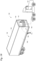
- FIG. 1A depicts a temperature-controlled straight truck 11 that includes a climate controlled space 12 for carrying cargo and a transport climate control system 10 for providing climate control to the climate controlled space 12.
- the transport climate control system 10 includes a transport climate control unit (TCCU) 14 that is mounted to a front wall 16 of the climate controlled space 12.
- the TCCU 14 includes a transport climate control circuit that connects, for example, a compressor, a condenser, an evaporator, and an expansion valve, and includes at least two fans and a damper to provide conditioned air within the climate controlled space 12.
- the climate control system 10 also includes a programmable climate controller 15 and one or more sensors (not shown) that are configured to measure one or more parameters of the climate control system 10 and communicate parameter data to the climate controller 15.
- the climate controller 15 may comprise a single integrated control unit or may comprise a distributed network of climate controller elements. The number of distributed control elements in a given network can depend upon the particular application of the principles described herein.
- the climate controller 15 is configured to control operation of the climate control system 10 including a transport climate control circuit.
- the truck 11 further includes a vehicle power bay 18, which houses a prime mover 21, such as a combustion engine (e.g., diesel engine, etc.), an electric motor, etc. that provides power to move the truck 11 and to operate the TCCU 14.
- a prime mover 21 can work in combination with an optional machine 22 (e.g., an alternator) to operate the TCCU 14.
- the truck 11 can be a hybrid vehicle that is powered by the prime mover 21 in combination with a battery power source or can be an electrically driven truck in which the prime mover 21 is replaced with an electric power source (e.g., a battery power source).
- the TCCU 14 can have its own independent power source (e.g., a TCCU prime mover, a TCCU alternator, a TCCU battery power source, etc.) that is separate from the prime mover 21 to provide power to and operate the TCCU 14.
- a TCCU prime mover can power the TCCU 14 by itself or in combination with a TCCU alternator or the optional machine 22 or a TCCU battery power source.
- the TCCU 14 can be powered by a TCCU electric power source (e.g., a battery power source) without the use of a prime mover (e.g., the prime mover 21, a TCCU prime mover, etc.).
- FIG. 1A illustrates a temperature-controlled straight truck 11
- TU transport unit
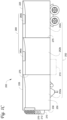
- FIG. 1B illustrates one embodiment of a refrigerated transport unit 105 attached to a tractor 120.
- the refrigerated transport unit 105 includes a transport climate control system 100 for a transport unit 125.
- the tractor 120 is attached to and is configured to tow the transport unit 125.
- the transport unit 125 shown in FIG. 1B is a trailer. It will be appreciated that the embodiments described herein are not limited to tractor and trailer units, but can apply to any type of transport unit (e.g., a container on a flat car, an intermodal container, etc.), a truck, a box car, or other similar transport unit.
- the transport unit 125 can include one or more doors (not shown) that are movable between an open position and a closed position to selectively allow access to a climate controlled space (e.g., internal or cargo space) 150.
- a climate controlled space e.g., internal or cargo space
- the transport climate control system 100 includes a climate control unit (CCU) 110 that provides environmental control (e.g. temperature, humidity, air quality, etc.) within the climate controlled space 150 of the transport unit 125.
- the climate control system 100 also includes a programmable climate controller 170 and one or more sensors (not shown) that are configured to measure one or more parameters of the climate control system 100 and communicate parameter data to the climate controller 170.
- the CCU 110 is disposed on a front wall 130 of the transport unit 125. In other embodiments, it will be appreciated that the CCU 110 can be disposed, for example, on a rooftop or another wall of the transport unit 125.
- the CCU 110 includes a transport climate control circuit that connects, for example, a compressor, a condenser, an evaporator and an expansion valve and includes at least two fans and a damper to provide conditioned air within the climate controlled space 150.
- the climate controller 170 may comprise a single integrated control unit 160 or may comprise a distributed network of climate controller elements 160, 165, which includes the control unit. The number of distributed control elements in a given network can depend upon the particular application of the principles described herein.
- the climate controller 170 is configured to control operation of the climate control system 100 including the transport climate control circuit.
- FIG. 1C illustrates one embodiment of a multi-zone transport climate control system (MCCS) 200 for a transport unit (TU) 225 that can be towed, for example, by a tractor (not shown).
- the MCCS 200 includes a transport climate control unit (TCCU) 210 that provides environmental control (e.g. temperature, humidity, air quality, etc.) within an internal climate controlled space 250 of the TU 225.
- TCCU transport climate control unit
- the MCCS 200 also includes a MCCS controller 270 and one or more sensors (e.g., Hall effect sensors, current transducers, etc.) that are configured to measure one or more parameters (e.g., ambient temperature, compressor suction pressure, compressor discharge pressure, supply air temperature, return air temperature, humidity, etc.) of the MCCS 200 and communicate parameter data to the MCCS controller 270.
- the MCCS 200 is powered by a power module 212.
- the TCCU 210 is disposed on a front wall 230 of the TU 225. In other embodiments, it will be appreciated that the TCCU 210 can be disposed, for example, on a rooftop 226 or another wall of the TU 225.
- the MCCS 200 can include an undermount unit 213.
- the undermount unit 213 can be a TCCU that can also provide environmental control (e.g. temperature, humidity, air quality, etc.) within the internal climate controlled space 250 of the TU 225.
- the undermount unit 213 can work in combination with the TCCU 210 to provide redundancy or can replace the TCCU 210.
- the undermount unit 213 can be a power module that includes, for example, a generator that can help power the TCCU 210.
- the programmable MCCS Controller 270 may comprise a single integrated control unit or may comprise a distributed network of control elements. The number of distributed control elements in a given network can depend upon the particular application of the principles described herein.
- the MCCS controller 270 is configured to control operation of the MCCS 200.
- the power module 212 is disposed in the TCCU 210. In other embodiments, the power module 212 can be separate from the TCCU 210. Also, in some embodiments, the power module 212 can include two or more different power sources disposed within or outside of the TCCU 210. In some embodiments, the power module 212 can include one or more of a prime mover, a battery, an alternator, a generator, a solar panel, a fuel cell, etc. Also, the prime mover can be a combustion engine or a microturbine engine and can operate as a two speed prime mover, a variable speed prime mover, etc.
- the power module 212 can provide power to, for example, the MCCS Controller 270, a compressor (not shown), a plurality of DC (Direct Current) components (not shown), a power management unit (not shown), etc.
- the DC components can be accessories or components of the MCCS 200 that require DC power to operate. Examples of the DC components can include, for example, DC fan motor(s) for a condenser fan or an evaporator blower (e.g., an Electrically Commutated Motor (ECM), a Brushless DC Motor (BLDC), etc.), a fuel pump, a drain tube heater, solenoid valves (e.g., controller pulsed control valves), etc.
- ECM Electrically Commutated Motor
- BLDC Brushless DC Motor
- the power module 212 can include a DC power source (not shown) for providing DC electrical power to the plurality of DC components (not shown), the power management unit (not shown), etc.
- the DC power source can receive mechanical and/or electrical power from, for example, a utility power source (e.g., Utility power, etc.), a prime mover (e.g., a combustion engine such as a diesel engine, etc.) coupled with a generator machine (e.g., a belt-driven alternator, a direct drive generator, etc.), a series of battery sources, etc.
- a utility power source e.g., Utility power, etc.
- a prime mover e.g., a combustion engine such as a diesel engine, etc.
- a generator machine e.g., a belt-driven alternator, a direct drive generator, etc.
- a series of battery sources e.g., a series of battery sources, etc.
- mechanical energy generated by a diesel engine is converted into electrical energy via a
- the internal climate controlled space 250 can be divided into a plurality of zones 252.
- the term "zone” means a part of an area of the internal climate controlled space 250 separated by walls 275. It will be appreciated that the invention disclosed herein can also be used in a single zone TCCU.
- the MCCS 200 for the TU 225 includes the TCCU 210 and a plurality of remote evaporator units 280.
- an HVAC system can be powered by an Auxiliary Power Unit.
- the APU can be operated when a main prime mover of the TU 225 is turned off such as, for example, when a driver parks the TU 225 for an extended period of time to rest.
- the APU can provide, for example, power to operate a secondary HVAC system to provide conditioned air to a cabin of the TU 225.
- the APU can also provide power to operate cabin accessories within the cabin such as a television, a microwave, a coffee maker, a refrigerator, etc.
- the APU can be a mechanically driven APU (e.g., prime mover driven) or an electrically driven APU (e.g., battery driven).
- the tractor includes a vehicle electrical system for supplying electrical power to the electrical loads of the tractor, the MCCS 200, and/or the TU 225.
- the tractor can include a compressor that can compress air and store the compressed air in compressor tank(s).
- FIG. 1D depicts a temperature-controlled van 300 that includes a climate controlled load space 320 (or internal space) for carrying cargo and a transport climate control system (TCCS) 305.
- the TCCS 305 includes a transport climate control unit (TCCU) 350 that is mounted to a rooftop 340 of the climate controlled load space 320.
- the TCCS 305 is controlled via a controller 330 to provide climate control within the climate controlled load space 320.
- the van 300 further includes a vehicle power bay 360, which houses a prime mover 370, such as a combustion engine (e.g., diesel engine, etc.) or battery power source, that provides power to move the van 300 and to operate the TCCS 305.
- a prime mover 370 such as a combustion engine (e.g., diesel engine, etc.) or battery power source, that provides power to move the van 300 and to operate the TCCS 305.
- the prime mover 370 can work in combination with an optional machine 380 (e.g., an alternator) to operate the TCCU 350.
- the van 300 includes a vehicle electrical system.
- the van 300 can be a hybrid vehicle that is powered by the prime mover 370 in combination with a battery power source or can be an electrically driven truck in which the prime mover 370 is replaced with an electric power source (e.g., a battery power source).
- FIG. 2 illustrates a block diagram of a transport climate control circuit 2000, according to one embodiment that can be used in any of the above transport climate control systems shown in FIGS. 1A-D .
- the transport climate control circuit 2000 can be, for example, a circuit that can be used to provide climate control within a passenger space of a vehicle (e.g., the climate controlled space 320 shown in FIG. 1D ), a circuit that can be used to provide climate control within an internal space or cargo space that is a climate controlled space of a transport unit (e.g., the climate controlled space 12, 150, 250, 320 shown in FIGS. 1A-D ), etc.
- a working fluid e.g., a refrigerant
- the transport climate control circuit 2000 includes at least a compressor 2010, a condenser 2020, an expansion device 2030, an evaporator 2040, and a heating device 2050.
- the compressor 2010 can be a digital scroll compressor, a reciprocating compressor, a screw compressor, a positive displacement compressor, a centrifugal compressor, or other suitable type of compressor for compressing a working fluid.
- a climate controller e.g., the controller 15, 170, 270, 330 shown in FIGS. 1A , 1B , 1C , 1D ) is configured to control the climate control circuit 2000 to operate in a plurality of different operation modes including, for example, a continuous cooling mode, a start-stop cooling mode, a heating mode, a defrost mode, etc.
- the climate controller in the continuous cooling mode, is configured to instruct the compressor 2010 to continuously compress the working fluid until the temperature within the climate controlled space reaches a desired setpoint temperature.
- the climate controller In the start-stop cooling mode, the climate controller is configured to instruct the compressor 2010 to operate in a periodic cycle in which during each cycle the compressor 2010 is configured to compress the working fluid for a first period of time and then the compressor 2010 is configured to stop compressing the working fluid for a second period of time. The compressor 2010 will continue to cycle between compressing the working fluid and not compressing the working fluid until the temperature within the climate controlled space reaches the desired setpoint temperature.
- the compressor 2010 is configured to compress the working fluid and direct the compressed working fluid from the compressor 2010 to the condenser 2020 during the start portion and configured to not compress working fluid during the stop portion. In some embodiments, during the stop portion of the start-stop cooling mode fan(s) of the condenser 2020 and the evaporator 2040 are turned off and are not operating.
- the compressor 2010 is configured to compress a working fluid (e.g., refrigerant) and direct the working fluid through the climate control circuit 2000 in order to provide temperature control within a climate controlled space.
- a working fluid e.g., refrigerant
- the compressor 2010 is configured to direct the compressed working fluid that is a gas to the condenser 2020.
- the condenser 2020 can include a condenser coil (not shown) and one or more condenser fans.
- the condenser 2020 is configured to allow the working fluid, received from the compressor 2010, to transform from a gas to a liquid by releasing heat absorbed by the working fluid into the ambient environment outside of the climate controlled space. That is, the condenser 2020 is configured to cool and condense the working fluid.
- the condenser 2020 is configured to direct the liquid working fluid to the expansion device 2030.
- the expansion device 2030 is configured to receive the working fluid in the form of a liquid from the condenser 2020 and is configured to restrict the flow of the working fluid in the form of a gas to the evaporator 2040.
- the expansion device 2030 can be an expansion valve.
- the gaseous working fluid is directed by the expansion device 2030 to the evaporator 2040.
- the evaporator 2040 can include an evaporator coil and two or more evaporator fans (described in detail below).
- the evaporator 2040 is configured to allow the working fluid, received from the expansion device 2030, to evaporate from a liquid to a gas by absorbing heat from the climate controlled space and thereby provide cooling to the climate controlled space.
- the transport climate control circuit 2000 can also include a heating device 2050 that can provide thermal energy for defrosting the evaporator 2040 or heat during the heating mode. This can allow for increased flexibility in defrost operation, such as, during frequent door openings of the climate controlled space (e.g., also referred to as door opening events).
- the heating device 2050 can be an electric heating device that uses heating coils or an electric heater having an electrical resistor that converts electricity to heat and/or an electric heating bar that is able to generate heat and/or includes a heating fin connected to the electric heating device, electric heater, or electric heating bar to conduct heat from the heating source to evenly distribute the supply of heat in the evaporator by having an increased area to increase the rate of heat transfer.
- the heating device 2050 can operate between 200 V DC and 2000 V DC, and preferably, between 330 V to 450 V DC, and nominally at 400 V DC, but it is appreciated that the electric heating device can be operated based on AC or DC voltage based on the specific unit/design of the electric heating device and/or at the voltage range for the operation of the transport unit. Also, in some embodiments, the discharge from the compressor 2010 having the compressed working fluid can be connected to the heating device 2050 (and optionally also including an electric heating element) to provide thermal energy to the evaporator 2040 in order to provide heating to the climate controlled space and/or the evaporator.
- heat sources can be used for providing heat to the heating device 2050, for example, a thermal storage system that uses brine or phase change material for capturing heat from the transport climate control circuit or other heating source from the transport unit, e.g., oil, exhaust, etc.
- FIGS. 3A and 3B illustrate the evaporator 2040 in further detail, according to one embodiment.
- the evaporator 2040 is used to absorb heat from the climate controlled space and evaporate the working fluid.
- the evaporator 2040 includes at least one evaporator coil having an inlet and outlet for receiving and returning the working fluid, at least two evaporator fans that control air flow around the evaporator coil, and at least one damper that moves between at least an open position and a closed position to control an amount of the air flow between the evaporator and the climate controlled space.
- the transport climate control circuit 2000 can also include the heating device 2050 to defrost the evaporator coil or provide heat during the heating mode and a controller to control the transport control circuit 2000, as necessary.
- the at least two evaporator fans can include a roadside evaporator fan 3010, e.g., fan nearer the middle/inner side of the road on which the transport unit is driven, e.g., a first side, and a curbside evaporator fan 3020, e.g., fan nearer the curb or outer side of the road on which the transport unit is driven, e.g., a second side.
- the at least two evaporator fans are used to control the air flow around specific sections of the evaporator coil, as described below.
- Additional evaporator fans can be used to control the amount of air flow around the evaporator coil, where the amount of evaporator fans are not limited hereto, but can be provided as required to meet the operating conditions of the transport climate control system.
- a third evaporator fan can be provided between the roadside evaporator fan and the curbside evaporator fan, where the third evaporator fan would be used to further selectively control the air flow around specific parts of the evaporator coil for controlled cooling and/or heating.
- the at least one evaporator coil can be a single evaporator coil 3030 that receives the working fluid from the expansion device at an inlet thereof, which is then evaporated by absorbing heat from the climate controlled space, and returns the working fluid to the compressor from the exit or outlet of the evaporator coil to continue the working fluid cycle.
- the at least one evaporator coil has sections or parts associated with the at least two evaporator fans for selective control of the air flow and can include at least a curbside section of the evaporator coil and at least a roadside section of the evaporator coil, which correspond to the same side as the roadside evaporator fan 3010 and the curbside evaporator fan 3020, respectively.
- the evaporator coil can be a single coil having an inlet(s) closest to the evaporator fans, multiple inlets along various sections of the evaporator coil, or the evaporator coil can be multiple separate evaporator coils connected along different flows paths in the evaporator with or without dividers, e.g., to provide different cooling profiles across the evaporator.
- the heating device 2050 can be controlled, for example, by the climate controller and can be connected to a high voltage power source, e.g., electric vehicle battery or battery charged from movement of a prime mover, or can be connected to another heat source, e.g., discharge outlet of the compressor or thermal storage system, for providing heat to the evaporator.
- the heating device can be heated, for example to have a surface temperature, between 93.3 °C (200 °F) and 426.7 °C (800 °F), and preferably between 176.7 °C (350 °F) and 260 °C (500 °F), and most preferably below 204.4 °C (400 °F) or similar temperature range that is sufficient to defrost the evaporator coil.
- FIG. 4 illustrates a flowchart for a method 4000 for providing thermal energy to the evaporator 2040 of the climate control circuit 2000 shown in FIG. 2 , according to one embodiment.
- the method 4000 begins at 4010 whereby a controller (e.g., the climate controller 15, 170, 270, 330 shown in FIGS. 1A - 1D ) determines whether a defrost event condition is detected/occurs in the transport climate control circuit 2000.
- the defrost event condition can be: a door opening event; a time condition, (e.g., every two minutes or every two hours, etc.); or based on pressure, temperature, and/or humidity data from sensors, or a combination thereof.
- the method 4000 proceeds to 4020, which can be an automatic event to defrost the evaporator coil or require user selection of the defrost mode.
- the controller determines that a defrost event is not triggered in the transport climate control circuit 2000, the method 4000 continues to loop until a defrost event is triggered.
- the controller begins operating in a defrost mode and closes the damper 3040 that separates the evaporator from the climate controlled space of a transport unit.
- the controller can operate a solenoid coupled to the damper.
- a valve (not shown in this embodiment) in the transport climate control circuit can be closed, preventing cold working fluid from flowing into the evaporator coil. The method 4000 then proceeds to 4030.
- the controller can defrost the evaporator coil by instructing the transport climate control circuit to supply heat to or around at least one section of the evaporator coil based on, among other things, mass of the ice/frost, size of the coil, airflow, etc.
- the controller can control the heating device, e.g., an electric heating device, to supply the marketing requested heat capacity for the heating device that is sufficient to perform defrost to heat around one section of the evaporator coil, e.g., by turning on the electric heating device to a specified temperature to generate heat, where the specified temperature is between 93.3 °C (200 °F) and 426.7 °C (800 °F), and preferably between 176.7 °C (350 °F) to 260 °C (500 °F), and most preferably at or below 204.4 °C (400 °F). It is appreciated that other heating sources can be optionally used to supply heat for defrosting the evaporator coil.
- the heating device e.g., an electric heating device
- the discharge temperature of the working fluid of the compressor is typically between 65.6-129.4 °C (150-265 °F)
- the discharge of the compressor can also be used as the heating source of the heating device, where the controller instructs the transport climate control circuit to supply heat to or around one section of the evaporator by instructing the transport climate control circuit to direct hot gas from the compressor to the evaporator coil.
- a thermal energy storage system can be used as the heat source, since such system captures heat from the working fluid for later reuse. It is appreciated that during the defrosting, the heat can be supplied solely by the electric heating device, e.g., without using the hot gas from the compressor discharge during defrosting, or in conjunction with the hot gas from the compressor through the evaporator coil. The method 4000 then proceeds to 4040.
- the controller independently controls two or more evaporator fans, e.g., evaporator fans 3010, 3020 in FIG. 3A , of the climate control circuit 2000 to convectively heat different portions or sections of the evaporator coil, i.e., so that heat from one section of the evaporator coil is used to heat and defrost the frost formed at a different portion or section of the evaporator coil.
- evaporator fans e.g., evaporator fans 3010, 3020 in FIG. 3A
- the controller independently controls operation of the evaporator fan to move air around the evaporator coil in a first controlled direction A, e.g., clockwise direction, so that the air is moved from an inlet of the evaporator coil to an exit or outlet of the evaporator coil along different sections of the evaporator coil, e.g., so that heat from the one section of the evaporator coil is used to convectively defrost frost formed at the inlet of the evaporator coil.
- a first controlled direction A e.g., clockwise direction
- FIG. 3A illustrates the operation of a first (or roadside) evaporator fan 3010, which draws air from the evaporator and forces the air across a first section (or roadside section) of the evaporator coil 3030 at an inlet of the evaporator coil at the roadside section of the evaporator coil and then across the roadside section of the evaporator coil and the heating device 2050.
- the air is then moved from around the exit/outlet of the evaporator coil and heating device across a second section (or curbside section) of the evaporator coil at the curbside section of the evaporator coil towards the inlet of the evaporator coil at the curbside section.
- frost formed at the inlet of the curbside section of the evaporator coil is defrosted by convection heating.
- the evaporator fans can be controlled at various speeds depending on the conditions necessary for defrost. That is, the evaporator fans can be run at a low speed, middle speed, or high speed, or combinations thereof for defrosting the evaporator coil.
- the controller can then stop the first evaporator fan 3010 and start the second (or curbside) evaporator fan 3020 as seen in FIG. 3B .
- the second evaporator fan 3020 moves air around the evaporator coil in a second controlled direction B, e.g., counterclockwise direction, where air is moved from the inlet of the evaporator coil to the exit or outlet of the evaporator coil along different sections of the evaporator coil.
- the second evaporator fan 3020 draws air from the evaporator and moves the air across the second section of the evaporator coil 3030 at the inlet of the evaporator coil at the curbside section of the evaporator coil and then across the curbside section of the evaporator coil and the heating device 2050.
- the air is then forced from the exit/outlet of the evaporator coil across the first section of the evaporator coil at roadside section of the evaporator coil towards the inlet of the evaporator coil at the roadside section.
- frost formed at the inlet of the first section/roadside section of the evaporator coil is defrosted by convection heating.
- controller can also control the evaporator fans in a positive air flow direction, where air is blown towards the evaporator coil, and in a negative air flow direction, where air is drawn from the evaporator coil to provide desired convection heating around the evaporator coil.
- the controller can control the operation of the curbside evaporator fan 3020 nearer the curbside section of the evaporator coil so that air is first drawn across the heating device 2050 and the exit/outlet of the evaporator coil at the curbside section of the evaporator coil so that the heated air is used to defrost the inlet of the evaporator coil at the curbside section of the evaporator coil, e.g., the evaporator coil on the same side as the evaporator fan.
- both fans can be operated at the same time, but in opposite directions.
- the first/roadside evaporator fan can be controlled to blow air in the positive air flow direction towards the roadside section of the evaporator coil
- the second/curbside evaporator fan is controlled in the negative air flow direction to draw air from curbside section of the evaporator coil. In this way, a greater air flow can be generated to convectively heat the evaporator.
- the method then optionally proceeds to 4050.
- the controller can optionally monitor parameters or conditions in the evaporator using sensors on or around the evaporator coil and/or in the climate controlled space to monitor at least one of temperature, pressure, or humidity, or combination thereof.
- monitoring the evaporator coil can include monitoring a temperature difference across the evaporator coil.
- one or more temperature sensors can be provided on the evaporator coil that provide evaporator coil temperature data across the evaporator coil.
- one or more pressure sensors can be provided for providing pressure data across the evaporator coil.
- monitoring the climate controlled space can include monitoring door openings of doors that access the climate controlled space (also referred to as door opening events), monitoring a temperature within the climate controlled space, etc. The method then proceeds to 4060.
- the controller determines whether or not the evaporator coil is sufficiently defrosted, e.g., by using the above mentioned sensors as discussed with respect to optional 4050. It is appreciated that while the determination of whether or not the evaporator coil is sufficiently defrosted can be based on sensors indicating that frost is still formed on the evaporator coil, it is understood that the evaporator fans can be started based on monitored/detected events or a programmed time, e.g., every two hours, or manually operated. If the evaporator coil is not sufficiently defrosted, the method returns to 4040 to independently control the two or more fans to continue the convection heating of the evaporator coil.
- the controller can then determine which of the evaporator fans should be running to defrost the evaporator coil, e.g., a temperature at the inlet of the roadside section of the evaporator coil is low, while the adjacent section of the evaporator coil at the curbside section of the evaporator coil does not indicate signs of frost formation, then the curbside evaporator would be run.
- the method proceeds to 4070.
- the controller exits the defrost mode and proceeds to 4080 to restart the previous operating mode (e.g., a continuous cooling mode, a start-stop cooling mode, a heating mode, etc.) and returns to 4010 to wait for the next defrost event to occur.
- the previous operating mode e.g., a continuous cooling mode, a start-stop cooling mode, a heating mode, etc.
- the method 4000 can provide heating energy that is efficient in defrosting the evaporator. Reducing total energy consumption and/or time by the transport climate control system can be important particularly for those transport climate control systems that rely on battery power for operations. This is because, for example, the energy storage can be expensive, heavy, and/or take valuable space of the transport vehicle.
- An advantage of these embodiments is that the transport climate control system can provide defrost to the evaporator coil without requiring additional energy to generate heat to remove any frost buildup.
- the defrosting mode can be used while the transport climate control system is providing cooling to improve cooling efficiency of the transport climate control system as a frosted evaporator coil can lower capacity and efficiency of the transport climate control system during cooling.
- FIG. 5 illustrates a block diagram of a transport climate control circuit 2000, according to another embodiment of the invention, having similar elements to FIG. 2 , but where a heating device is not provided in the evaporator. Instead, hot gas from the compressor is used to defrost the evaporator.
- the transport climate control circuit 5000 includes at least a compressor 5010, a condenser 5020, an expansion device 5030, and an evaporator 5040.
- the first valve 5050 which is provided between the exit of the compressor 5010 and the condenser 5020 can be closed, either manually or automatically by the controller.
- the second valve 5060 can then be opened to circulate the hot gas from the compressor discharge to the inlet of the evaporator coil of the evaporator 5040.
- the hot gas can be provided at different sections of the evaporator coil, e.g., multiple or different inlets to the evaporator coil, along different sections of the evaporator coil using valves, or at the exit/outlet of the evaporator coil and/or the different sections of the evaporator can be divided using dividers.
- the hot gas is not used to directly heat the frost formation on the evaporator coil, which typically occurs at the inlet of the evaporator coil, but can be used with the evaporator fans, as discussed above, so that convective heating of the evaporator can occur by the independent control of the evaporator fans to move the air around the evaporator coil in controlled directions (e.g. a respective controlled direction for each one of the fans) so that heat from one section of the evaporator coil is used to convectively defrost the frost formed on the evaporator coil.
- controlled directions e.g. a respective controlled direction for each one of the fans
Landscapes
- Physics & Mathematics (AREA)
- Thermal Sciences (AREA)
- Engineering & Computer Science (AREA)
- Mechanical Engineering (AREA)
- Devices That Are Associated With Refrigeration Equipment (AREA)
Claims (10)
- Transportklimatisierungsanlage (10, 100, 200, 305) zur Klimatisierung eines klimatisierten Raums (12, 150, 250, 320) einer Transporteinheit (125, 225), wobei die Transportklimatisierungsanlage umfasst:
einen Transportklimatisierungskreis (2000), umfassend:einen Kompressor (2010), der eine Arbeitsflüssigkeit komprimiert, die durch den Transportklimatisierungskreis strömt,einen Verdampfer (2040), der Wärme aus dem klimatisierten Raum aufnimmt und die Arbeitsflüssigkeit verdampft, wobei der Verdampfer umfasst:eine Verdampferschlange (3030) mit einem Einlass zum Empfangen der Arbeitsflüssigkeit und einem Auslass zum Rückführen der Arbeitsflüssigkeit,mindestens zwei Ventilatoren (3010, 3020), die den Luftstrom um eine erste Seite der Verdampferschlange (3030) und eine zweite Seite der Verdampferschlange (3030) steuern,dadurch gekennzeichnet, dass die Anlage eine elektrische Heizvorrichtung (2050) umfasst, die an einem Auslass der Verdampferschlange (3030) positioniert und zur Wärmeerzeugung ausgelegt ist, wobei die elektrische Heizvorrichtung (2050) sich über die Verdampferschlange (3030) zwischen der ersten und der zweiten Seite erstreckt, undeine Klappe (3040), die sich zwischen mindestens einer geöffneten Stellung und einer geschlossenen Stellung bewegt, um den Verdampfer vom klimatisierten Raum zu trennen und eine Menge des Luftstroms zwischen dem Verdampfer und dem klimatisierten Raum zu steuern,eine Steuervorrichtung (15, 170, 270, 330), die zum Steuern des Transportklimatisierungskreises ausgelegt ist und zum Abtauen der Verdampferschlange (3030) ausgelegt ist durch:Schließen der Klappe (3040), wenn ein Abtauvorgang ausgelöst wird, um den Verdampfer von dem klimatisierten Raum zu trennen,Anweisen des Transportklimatisierungskreises, einen Abschnitt der Verdampferschlange (3030) mit Wärme zu versorgen, indem die elektrische Heizvorrichtung (2050) eingeschaltet wird, um Wärme zu erzeugen, undunabhängiges Steuern jedes der mindestens zwei Ventilatoren (3010, 3020), um die Luft um die Verdampferschlange (3030) in einer gesteuerten Richtung zu bewegen, sodass die Wärme aus dem einen Abschnitt der Verdampferschlange (3030) zur konvektiven Erwärmung des Einlasses der Verdampferschlange verwendet wird. - Transportklimatisierungsanlage nach Anspruch 1, wobei das Anweisen des Transportklimatisierungskreises, Wärme an oder um den einen Abschnitt der Verdampferschlange zu liefern, das Anweisen des Transportklimatisierungskreises umfasst, heißes Gas aus dem Kompressor zur Verdampferschlange zu leiten.
- Transportklimatisierungsanlage nach einem der Ansprüche 1-2, ferner umfassend eine Heizrippe, die dazu ausgelegt ist, die Wärme aus der Wärmezufuhr entlang der Verdampferschlange gleichmäßig zu verteilen.
- Transportklimatisierungsanlage nach einem der Ansprüche 1-3, wobei die mindestens zwei Ventilatoren jeweils dazu ausgelegt sind, in positiver Luftstromrichtung durch Blasen von Luft zur Verdampferschlange (3030) und in negativer Luftstromrichtung durch Ansaugen von Luft von der Verdampferschlange (3030) zu arbeiten, und/oder wobei mindestens ein dritter Ventilator vorgesehen ist, um den Luftstrom um die Verdampferschlange des Verdampfers weiter zu steuern, und/oder
wobei die Steuervorrichtung (15, 170, 270, 330) dazu ausgelegt ist, die Verdampferschlange (3030) des Verdampfers zu überwachen, indem sie mindestens eines von den Temperaturdaten der Verdampferschlange und den Druckdaten des Verdampfers über die Verdampferschlange überwacht und die Verdampferschlange automatisch abtaut. - Verfahren zum Abtauen eines Verdampfers eines Transportklimatisierungskreises einer Transportklimatisierungsanlage, die einen klimatisierten Raum einer Transporteinheit klimatisiert, wobei der Transportklimatisierungskreis einen Kompressor, einen Verdampfer, der eine Verdampferschlange mit einem Einlass zum Empfangen einer Arbeitsflüssigkeit und einem Auslass zum Empfangen der Arbeitsflüssigkeit aufweist, mindestens zwei Ventilatoren und eine elektrische Heizvorrichtung und eine Klappe aufweist, die sich mindestens zwischen einer geöffneten und einer geschlossenen Stellung bewegt, um den Verdampfer vom klimatisierten Raum zu trennen und eine Menge des Luftstroms zwischen dem Verdampfer und dem klimatisierten Raum zu steuern, wobei das Verfahren umfasst:eine Steuervorrichtung der Transportklimatisierungsanlage, die einen Abtauvorgangszustand erkennt;bei Erkennung des Abtauvorgangszustands:Schließen der Klappe (3040), wenn ein Abtauvorgang ausgelöst wird, um den Verdampfer von dem klimatisierten Raum zu trennen,Zuführen von Wärme zu oder um einen Abschnitt der Verdampferschlange (3030) durch Einschalten der elektrischen Heizvorrichtung (2050), um Wärme zu erzeugen, wobei die elektrische Heizvorrichtung an einem Auslass der Verdampferschlange (3030) positioniert ist und sich über die Verdampferschlange zwischen einer ersten Seite und einer zweiten Seite der Verdampferschlange erstreckt;unabhängiges Steuern eines ersten Ventilators der mindestens zwei Ventilatoren, um Luft um die Verdampferschlange in einer ersten gesteuerten Richtung zu bewegen, sodass die Wärme aus dem einen Abschnitt der Verdampferschlange verwendet wird, um den Einlass an der ersten Seite der Verdampferschlange konvektiv zu erwärmen, undunabhängiges Steuern eines zweiten Ventilators der mindestens zwei Ventilatoren, um Luft um die Verdampferschlange in einer zweiten gesteuerten Richtung zu bewegen, sodass die Wärme aus dem einen Abschnitt der Verdampferschlange verwendet wird, um den Einlass an der zweiten Seite der Verdampferschlange konvektiv zu erwärmen.
- Verfahren zum Abtauen des Verdampfers nach Anspruch 5, wobei das unabhängige Steuern des ersten Ventilators der mindestens zwei Ventilatoren, um Luft um die Verdampferschlange in der ersten gesteuerten Richtung zu bewegen, den ersten Ventilator umfasst, der Luft vom Einlass der Verdampferschlange an der ersten Seite der Verdampferschlange zum Auslass der Verdampferschlange an der ersten Seite der Verdampferschlange und vom Auslass der Verdampferschlange an der zweiten Seite der Verdampferschlange zum Einlass des Verdampfers an der zweiten Seite der Verdampferschlange bewegt.
- Verfahren zum Abtauen des Verdampfers nach Anspruch 5 oder 6, wobei das unabhängige Steuern des ersten Ventilators der mindestens zwei Ventilatoren, um Luft um die Verdampferschlange in der ersten gesteuerten Richtung zu bewegen, den ersten Ventilator umfasst, der Luft vom Auslass der Verdampferschlange an der ersten Seite der Verdampferschlange zum Einlass der Verdampferschlange an der ersten Seite der Verdampferschlange bewegt.
- Verfahren zum Abtauen des Verdampfers nach einem der Ansprüche 5-7, ferner umfassend das Steuern der Erwärmung des Bereichs um den Verdampfer über die elektrische Heizvorrichtung, bis die Verdampferschlange abgetaut ist.
- Verfahren zum Abtauen des Verdampfers nach einem der Ansprüche 5-8, ferner umfassend: Überwachen eines Verdampfungsparameters der Verdampferschlange; und Wärmeversorgung des Verdampfers auf Grundlage des Verdampfungsparameters.
- Verfahren zum Abtauen des Verdampfers nach Anspruch 9, wobei das Überwachen des Verdampfungsparameters das Überwachen mindestens eines der Temperaturdaten der Verdampferschlange und der Druckdaten des Verdampfers über die Verdampferschlange umfasst.
Applications Claiming Priority (1)
| Application Number | Priority Date | Filing Date | Title |
|---|---|---|---|
| US17/407,561 US11970048B2 (en) | 2021-08-20 | 2021-08-20 | Methods and systems for defrosting a transport climate control system evaporator |
Publications (3)
| Publication Number | Publication Date |
|---|---|
| EP4137340A1 EP4137340A1 (de) | 2023-02-22 |
| EP4137340C0 EP4137340C0 (de) | 2024-11-20 |
| EP4137340B1 true EP4137340B1 (de) | 2024-11-20 |
Family
ID=83004711
Family Applications (1)
| Application Number | Title | Priority Date | Filing Date |
|---|---|---|---|
| EP22191277.7A Active EP4137340B1 (de) | 2021-08-20 | 2022-08-19 | Verfahren und systeme zum abtauen eines transportklimatisierungsanlagenverdampfers |
Country Status (3)
| Country | Link |
|---|---|
| US (1) | US11970048B2 (de) |
| EP (1) | EP4137340B1 (de) |
| CN (1) | CN115891582A (de) |
Families Citing this family (2)
| Publication number | Priority date | Publication date | Assignee | Title |
|---|---|---|---|---|
| CN117087389B (zh) * | 2023-09-28 | 2025-08-22 | 赛力斯汽车有限公司 | 一种防结霜的汽车热泵空调系统和汽车 |
| US20250376003A1 (en) * | 2024-06-05 | 2025-12-11 | Thermo King Llc | Methods and systems for reducing ice/frost buildup in an evaporator blower space of a transport climate control system |
Family Cites Families (11)
| Publication number | Priority date | Publication date | Assignee | Title |
|---|---|---|---|---|
| US3359751A (en) * | 1966-10-14 | 1967-12-26 | Admiral Corp | Two temperature refrigerator |
| US3559421A (en) | 1969-02-07 | 1971-02-02 | Halstead & Mitchell Co | Refrigeration defrost system with receiver heat source |
| US5406805A (en) | 1993-11-12 | 1995-04-18 | University Of Maryland | Tandem refrigeration system |
| US6694765B1 (en) * | 2002-07-30 | 2004-02-24 | Thermo King Corporation | Method and apparatus for moving air through a heat exchanger |
| JP2004085109A (ja) | 2002-08-28 | 2004-03-18 | Toko Reinetsu Engineering:Kk | 冷凍車 |
| JP2005226875A (ja) | 2004-02-10 | 2005-08-25 | Mitsubishi Heavy Ind Ltd | 冷蔵・冷凍装置及び冷蔵方法 |
| WO2011022331A2 (en) | 2009-08-18 | 2011-02-24 | Carrier Corporation | Damper apparatus for transport refrigeration system, transport refrigeration unit, and methods for same |
| US20120023993A1 (en) * | 2010-07-27 | 2012-02-02 | Palmer Roger C | Evaporator with integrated heating element |
| EP3830503B1 (de) * | 2018-07-30 | 2023-11-01 | Carrier Corporation | Abtausystem und verfahren zum abtauen eines verdampferteils eines temperiergeräts |
| US10907879B2 (en) * | 2018-12-31 | 2021-02-02 | Thermo King Corporation | Methods and systems for energy efficient defrost of a transport climate control system evaporator |
| US12442671B2 (en) * | 2019-08-16 | 2025-10-14 | Thermo King Llc | Environmental sensor for transport refrigeration |
-
2021
- 2021-08-20 US US17/407,561 patent/US11970048B2/en active Active
-
2022
- 2022-08-19 CN CN202210998392.XA patent/CN115891582A/zh active Pending
- 2022-08-19 EP EP22191277.7A patent/EP4137340B1/de active Active
Also Published As
| Publication number | Publication date |
|---|---|
| US20230059306A1 (en) | 2023-02-23 |
| US11970048B2 (en) | 2024-04-30 |
| EP4137340C0 (de) | 2024-11-20 |
| CN115891582A (zh) | 2023-04-04 |
| EP4137340A1 (de) | 2023-02-22 |
Similar Documents
| Publication | Publication Date | Title |
|---|---|---|
| KR101472689B1 (ko) | 하이브리드 서브타입 차량용 냉동기 시스템 | |
| CN105555564B (zh) | 热泵式车辆用空调系统以及其除霜方法 | |
| CA2621931C (en) | Vehicle air conditioning and heating system providing engine on and off operation | |
| EP3680117B1 (de) | Verfahren und systeme zum energieeffizienten abtauen eines transportklimaanlagenverdampfers | |
| US9834063B2 (en) | Heat pump system for vehicle | |
| US6988371B2 (en) | Automotive HVAC system and method of operating same utilizing evaporator freezing | |
| EP3481657B1 (de) | Doppelverdichter-transportkühlaggregat | |
| US20120227431A1 (en) | Heat pump system for vehicle | |
| EP2418111A1 (de) | Fahrzeugklimaanlagensystem | |
| US6694765B1 (en) | Method and apparatus for moving air through a heat exchanger | |
| JPH08197937A (ja) | 車両用空気調和装置 | |
| EP4137340B1 (de) | Verfahren und systeme zum abtauen eines transportklimatisierungsanlagenverdampfers | |
| EP3386786B1 (de) | Klimaanlage zur verwendung in einem fahrzeug | |
| JP2010197021A (ja) | 温度調節装置 | |
| JP5925048B2 (ja) | 車両用空調装置及び車両 | |
| NL2015702B1 (en) | Cargo space unit for a vehicle. | |
| JP2017218109A (ja) | 車両用冷凍装置および冷凍車両 | |
| JP2010076587A (ja) | 輸送車両のキャビン空調装置 | |
| US20250376003A1 (en) | Methods and systems for reducing ice/frost buildup in an evaporator blower space of a transport climate control system | |
| JP2000105045A (ja) | 冷凍装置及び、車両搭載冷凍庫 |
Legal Events
| Date | Code | Title | Description |
|---|---|---|---|
| PUAI | Public reference made under article 153(3) epc to a published international application that has entered the european phase |
Free format text: ORIGINAL CODE: 0009012 |
|
| STAA | Information on the status of an ep patent application or granted ep patent |
Free format text: STATUS: THE APPLICATION HAS BEEN PUBLISHED |
|
| AK | Designated contracting states |
Kind code of ref document: A1 Designated state(s): AL AT BE BG CH CY CZ DE DK EE ES FI FR GB GR HR HU IE IS IT LI LT LU LV MC MK MT NL NO PL PT RO RS SE SI SK SM TR |
|
| RAP3 | Party data changed (applicant data changed or rights of an application transferred) |
Owner name: THERMO KING LLC |
|
| STAA | Information on the status of an ep patent application or granted ep patent |
Free format text: STATUS: REQUEST FOR EXAMINATION WAS MADE |
|
| 17P | Request for examination filed |
Effective date: 20230818 |
|
| RBV | Designated contracting states (corrected) |
Designated state(s): AL AT BE BG CH CY CZ DE DK EE ES FI FR GB GR HR HU IE IS IT LI LT LU LV MC MK MT NL NO PL PT RO RS SE SI SK SM TR |
|
| GRAP | Despatch of communication of intention to grant a patent |
Free format text: ORIGINAL CODE: EPIDOSNIGR1 |
|
| RIC1 | Information provided on ipc code assigned before grant |
Ipc: B60H 1/00 20060101ALN20240506BHEP Ipc: B60H 1/32 20060101AFI20240506BHEP |
|
| STAA | Information on the status of an ep patent application or granted ep patent |
Free format text: STATUS: GRANT OF PATENT IS INTENDED |
|
| RIC1 | Information provided on ipc code assigned before grant |
Ipc: B60H 1/00 20060101ALN20240516BHEP Ipc: B60H 1/32 20060101AFI20240516BHEP |
|
| INTG | Intention to grant announced |
Effective date: 20240613 |
|
| GRAS | Grant fee paid |
Free format text: ORIGINAL CODE: EPIDOSNIGR3 |
|
| GRAA | (expected) grant |
Free format text: ORIGINAL CODE: 0009210 |
|
| STAA | Information on the status of an ep patent application or granted ep patent |
Free format text: STATUS: THE PATENT HAS BEEN GRANTED |
|
| AK | Designated contracting states |
Kind code of ref document: B1 Designated state(s): AL AT BE BG CH CY CZ DE DK EE ES FI FR GB GR HR HU IE IS IT LI LT LU LV MC MK MT NL NO PL PT RO RS SE SI SK SM TR |
|
| REG | Reference to a national code |
Ref country code: GB Ref legal event code: FG4D |
|
| REG | Reference to a national code |
Ref country code: CH Ref legal event code: EP |
|
| REG | Reference to a national code |
Ref country code: DE Ref legal event code: R096 Ref document number: 602022007860 Country of ref document: DE |
|
| REG | Reference to a national code |
Ref country code: IE Ref legal event code: FG4D |
|
| U01 | Request for unitary effect filed |
Effective date: 20241210 |
|
| U07 | Unitary effect registered |
Designated state(s): AT BE BG DE DK EE FI FR IT LT LU LV MT NL PT RO SE SI Effective date: 20241220 |
|
| PG25 | Lapsed in a contracting state [announced via postgrant information from national office to epo] |
Ref country code: HR Free format text: LAPSE BECAUSE OF FAILURE TO SUBMIT A TRANSLATION OF THE DESCRIPTION OR TO PAY THE FEE WITHIN THE PRESCRIBED TIME-LIMIT Effective date: 20241120 Ref country code: IS Free format text: LAPSE BECAUSE OF FAILURE TO SUBMIT A TRANSLATION OF THE DESCRIPTION OR TO PAY THE FEE WITHIN THE PRESCRIBED TIME-LIMIT Effective date: 20250320 |
|
| PG25 | Lapsed in a contracting state [announced via postgrant information from national office to epo] |
Ref country code: ES Free format text: LAPSE BECAUSE OF FAILURE TO SUBMIT A TRANSLATION OF THE DESCRIPTION OR TO PAY THE FEE WITHIN THE PRESCRIBED TIME-LIMIT Effective date: 20241120 |
|
| PG25 | Lapsed in a contracting state [announced via postgrant information from national office to epo] |
Ref country code: NO Free format text: LAPSE BECAUSE OF FAILURE TO SUBMIT A TRANSLATION OF THE DESCRIPTION OR TO PAY THE FEE WITHIN THE PRESCRIBED TIME-LIMIT Effective date: 20250220 |
|
| PG25 | Lapsed in a contracting state [announced via postgrant information from national office to epo] |
Ref country code: GR Free format text: LAPSE BECAUSE OF FAILURE TO SUBMIT A TRANSLATION OF THE DESCRIPTION OR TO PAY THE FEE WITHIN THE PRESCRIBED TIME-LIMIT Effective date: 20250221 |
|
| PG25 | Lapsed in a contracting state [announced via postgrant information from national office to epo] |
Ref country code: PL Free format text: LAPSE BECAUSE OF FAILURE TO SUBMIT A TRANSLATION OF THE DESCRIPTION OR TO PAY THE FEE WITHIN THE PRESCRIBED TIME-LIMIT Effective date: 20241120 |
|
| PG25 | Lapsed in a contracting state [announced via postgrant information from national office to epo] |
Ref country code: RS Free format text: LAPSE BECAUSE OF FAILURE TO SUBMIT A TRANSLATION OF THE DESCRIPTION OR TO PAY THE FEE WITHIN THE PRESCRIBED TIME-LIMIT Effective date: 20250220 |
|
| PG25 | Lapsed in a contracting state [announced via postgrant information from national office to epo] |
Ref country code: SM Free format text: LAPSE BECAUSE OF FAILURE TO SUBMIT A TRANSLATION OF THE DESCRIPTION OR TO PAY THE FEE WITHIN THE PRESCRIBED TIME-LIMIT Effective date: 20241120 |
|
| PG25 | Lapsed in a contracting state [announced via postgrant information from national office to epo] |
Ref country code: SK Free format text: LAPSE BECAUSE OF FAILURE TO SUBMIT A TRANSLATION OF THE DESCRIPTION OR TO PAY THE FEE WITHIN THE PRESCRIBED TIME-LIMIT Effective date: 20241120 |
|
| PG25 | Lapsed in a contracting state [announced via postgrant information from national office to epo] |
Ref country code: CZ Free format text: LAPSE BECAUSE OF FAILURE TO SUBMIT A TRANSLATION OF THE DESCRIPTION OR TO PAY THE FEE WITHIN THE PRESCRIBED TIME-LIMIT Effective date: 20241120 |
|
| U20 | Renewal fee for the european patent with unitary effect paid |
Year of fee payment: 4 Effective date: 20250723 |
|
| PLBE | No opposition filed within time limit |
Free format text: ORIGINAL CODE: 0009261 |
|
| STAA | Information on the status of an ep patent application or granted ep patent |
Free format text: STATUS: NO OPPOSITION FILED WITHIN TIME LIMIT |
|
| 26N | No opposition filed |
Effective date: 20250821 |