EP4134586B1 - Beleuchtungsvorrichtung zur abbildung einer virtuellen beleuchteten oberfläche eines kollektors - Google Patents
Beleuchtungsvorrichtung zur abbildung einer virtuellen beleuchteten oberfläche eines kollektors Download PDFInfo
- Publication number
- EP4134586B1 EP4134586B1 EP22198166.5A EP22198166A EP4134586B1 EP 4134586 B1 EP4134586 B1 EP 4134586B1 EP 22198166 A EP22198166 A EP 22198166A EP 4134586 B1 EP4134586 B1 EP 4134586B1
- Authority
- EP
- European Patent Office
- Prior art keywords
- collector
- light source
- light
- optical axis
- luminous device
- Prior art date
- Legal status (The legal status is an assumption and is not a legal conclusion. Google has not performed a legal analysis and makes no representation as to the accuracy of the status listed.)
- Active
Links
Images

Classifications
-
- F—MECHANICAL ENGINEERING; LIGHTING; HEATING; WEAPONS; BLASTING
- F21—LIGHTING
- F21S—NON-PORTABLE LIGHTING DEVICES; SYSTEMS THEREOF; VEHICLE LIGHTING DEVICES SPECIALLY ADAPTED FOR VEHICLE EXTERIORS
- F21S41/00—Illuminating devices specially adapted for vehicle exteriors, e.g. headlamps
- F21S41/10—Illuminating devices specially adapted for vehicle exteriors, e.g. headlamps characterised by the light source
- F21S41/14—Illuminating devices specially adapted for vehicle exteriors, e.g. headlamps characterised by the light source characterised by the type of light source
- F21S41/141—Light emitting diodes [LED]
- F21S41/147—Light emitting diodes [LED] the main emission direction of the LED being angled to the optical axis of the illuminating device
-
- B—PERFORMING OPERATIONS; TRANSPORTING
- B60—VEHICLES IN GENERAL
- B60Q—ARRANGEMENT OF SIGNALLING OR LIGHTING DEVICES, THE MOUNTING OR SUPPORTING THEREOF OR CIRCUITS THEREFOR, FOR VEHICLES IN GENERAL
- B60Q1/00—Arrangement of optical signalling or lighting devices, the mounting or supporting thereof or circuits therefor
- B60Q1/02—Arrangement of optical signalling or lighting devices, the mounting or supporting thereof or circuits therefor the devices being primarily intended to illuminate the way ahead or to illuminate other areas of way or environments
- B60Q1/04—Arrangement of optical signalling or lighting devices, the mounting or supporting thereof or circuits therefor the devices being primarily intended to illuminate the way ahead or to illuminate other areas of way or environments the devices being headlights
- B60Q1/14—Arrangement of optical signalling or lighting devices, the mounting or supporting thereof or circuits therefor the devices being primarily intended to illuminate the way ahead or to illuminate other areas of way or environments the devices being headlights having dimming means
-
- F—MECHANICAL ENGINEERING; LIGHTING; HEATING; WEAPONS; BLASTING
- F21—LIGHTING
- F21S—NON-PORTABLE LIGHTING DEVICES; SYSTEMS THEREOF; VEHICLE LIGHTING DEVICES SPECIALLY ADAPTED FOR VEHICLE EXTERIORS
- F21S41/00—Illuminating devices specially adapted for vehicle exteriors, e.g. headlamps
- F21S41/10—Illuminating devices specially adapted for vehicle exteriors, e.g. headlamps characterised by the light source
- F21S41/14—Illuminating devices specially adapted for vehicle exteriors, e.g. headlamps characterised by the light source characterised by the type of light source
- F21S41/141—Light emitting diodes [LED]
- F21S41/147—Light emitting diodes [LED] the main emission direction of the LED being angled to the optical axis of the illuminating device
- F21S41/148—Light emitting diodes [LED] the main emission direction of the LED being angled to the optical axis of the illuminating device the main emission direction of the LED being perpendicular to the optical axis
-
- F—MECHANICAL ENGINEERING; LIGHTING; HEATING; WEAPONS; BLASTING
- F21—LIGHTING
- F21S—NON-PORTABLE LIGHTING DEVICES; SYSTEMS THEREOF; VEHICLE LIGHTING DEVICES SPECIALLY ADAPTED FOR VEHICLE EXTERIORS
- F21S41/00—Illuminating devices specially adapted for vehicle exteriors, e.g. headlamps
- F21S41/20—Illuminating devices specially adapted for vehicle exteriors, e.g. headlamps characterised by refractors, transparent cover plates, light guides or filters
- F21S41/25—Projection lenses
-
- F—MECHANICAL ENGINEERING; LIGHTING; HEATING; WEAPONS; BLASTING
- F21—LIGHTING
- F21S—NON-PORTABLE LIGHTING DEVICES; SYSTEMS THEREOF; VEHICLE LIGHTING DEVICES SPECIALLY ADAPTED FOR VEHICLE EXTERIORS
- F21S41/00—Illuminating devices specially adapted for vehicle exteriors, e.g. headlamps
- F21S41/30—Illuminating devices specially adapted for vehicle exteriors, e.g. headlamps characterised by reflectors
- F21S41/32—Optical layout thereof
- F21S41/321—Optical layout thereof the reflector being a surface of revolution or a planar surface, e.g. truncated
-
- F—MECHANICAL ENGINEERING; LIGHTING; HEATING; WEAPONS; BLASTING
- F21—LIGHTING
- F21S—NON-PORTABLE LIGHTING DEVICES; SYSTEMS THEREOF; VEHICLE LIGHTING DEVICES SPECIALLY ADAPTED FOR VEHICLE EXTERIORS
- F21S41/00—Illuminating devices specially adapted for vehicle exteriors, e.g. headlamps
- F21S41/30—Illuminating devices specially adapted for vehicle exteriors, e.g. headlamps characterised by reflectors
- F21S41/32—Optical layout thereof
- F21S41/33—Multi-surface reflectors, e.g. reflectors with facets or reflectors with portions of different curvature
- F21S41/338—Multi-surface reflectors, e.g. reflectors with facets or reflectors with portions of different curvature the reflector having surface portions added to its general concavity
-
- F—MECHANICAL ENGINEERING; LIGHTING; HEATING; WEAPONS; BLASTING
- F21—LIGHTING
- F21S—NON-PORTABLE LIGHTING DEVICES; SYSTEMS THEREOF; VEHICLE LIGHTING DEVICES SPECIALLY ADAPTED FOR VEHICLE EXTERIORS
- F21S41/00—Illuminating devices specially adapted for vehicle exteriors, e.g. headlamps
- F21S41/30—Illuminating devices specially adapted for vehicle exteriors, e.g. headlamps characterised by reflectors
- F21S41/32—Optical layout thereof
- F21S41/36—Combinations of two or more separate reflectors
- F21S41/365—Combinations of two or more separate reflectors successively reflecting the light
-
- F—MECHANICAL ENGINEERING; LIGHTING; HEATING; WEAPONS; BLASTING
- F21—LIGHTING
- F21S—NON-PORTABLE LIGHTING DEVICES; SYSTEMS THEREOF; VEHICLE LIGHTING DEVICES SPECIALLY ADAPTED FOR VEHICLE EXTERIORS
- F21S41/00—Illuminating devices specially adapted for vehicle exteriors, e.g. headlamps
- F21S41/60—Illuminating devices specially adapted for vehicle exteriors, e.g. headlamps characterised by a variable light distribution
-
- F—MECHANICAL ENGINEERING; LIGHTING; HEATING; WEAPONS; BLASTING
- F21—LIGHTING
- F21V—FUNCTIONAL FEATURES OR DETAILS OF LIGHTING DEVICES OR SYSTEMS THEREOF; STRUCTURAL COMBINATIONS OF LIGHTING DEVICES WITH OTHER ARTICLES, NOT OTHERWISE PROVIDED FOR
- F21V13/00—Producing particular characteristics or distribution of the light emitted by means of a combination of elements specified in two or more of main groups F21V1/00 - F21V11/00
- F21V13/02—Combinations of only two kinds of elements
- F21V13/04—Combinations of only two kinds of elements the elements being reflectors and refractors
-
- F—MECHANICAL ENGINEERING; LIGHTING; HEATING; WEAPONS; BLASTING
- F21—LIGHTING
- F21V—FUNCTIONAL FEATURES OR DETAILS OF LIGHTING DEVICES OR SYSTEMS THEREOF; STRUCTURAL COMBINATIONS OF LIGHTING DEVICES WITH OTHER ARTICLES, NOT OTHERWISE PROVIDED FOR
- F21V5/00—Refractors for light sources
- F21V5/04—Refractors for light sources of lens shape
-
- F—MECHANICAL ENGINEERING; LIGHTING; HEATING; WEAPONS; BLASTING
- F21—LIGHTING
- F21V—FUNCTIONAL FEATURES OR DETAILS OF LIGHTING DEVICES OR SYSTEMS THEREOF; STRUCTURAL COMBINATIONS OF LIGHTING DEVICES WITH OTHER ARTICLES, NOT OTHERWISE PROVIDED FOR
- F21V7/00—Reflectors for light sources
- F21V7/04—Optical design
-
- F—MECHANICAL ENGINEERING; LIGHTING; HEATING; WEAPONS; BLASTING
- F21—LIGHTING
- F21W—INDEXING SCHEME ASSOCIATED WITH SUBCLASSES F21K, F21L, F21S and F21V, RELATING TO USES OR APPLICATIONS OF LIGHTING DEVICES OR SYSTEMS
- F21W2102/00—Exterior vehicle lighting devices for illuminating purposes
-
- F—MECHANICAL ENGINEERING; LIGHTING; HEATING; WEAPONS; BLASTING
- F21—LIGHTING
- F21W—INDEXING SCHEME ASSOCIATED WITH SUBCLASSES F21K, F21L, F21S and F21V, RELATING TO USES OR APPLICATIONS OF LIGHTING DEVICES OR SYSTEMS
- F21W2107/00—Use or application of lighting devices on or in particular types of vehicles
- F21W2107/10—Use or application of lighting devices on or in particular types of vehicles for land vehicles
-
- F—MECHANICAL ENGINEERING; LIGHTING; HEATING; WEAPONS; BLASTING
- F21—LIGHTING
- F21Y—INDEXING SCHEME ASSOCIATED WITH SUBCLASSES F21K, F21L, F21S and F21V, RELATING TO THE FORM OR THE KIND OF THE LIGHT SOURCES OR OF THE COLOUR OF THE LIGHT EMITTED
- F21Y2115/00—Light-generating elements of semiconductor light sources
- F21Y2115/10—Light-emitting diodes [LED]
Definitions
- the invention relates to the field of lighting and light signaling, more particularly in the automotive field.
- the published patent document FR 3 047 541 A1 discloses a lighting device comprising two optical modules arranged opposite each other.
- Each of these two optical modules essentially comprises a light source and a collector with a reflective surface. These two light sources are arranged on two opposite faces of a common support.
- Each of the reflective surfaces is a surface of revolution in a half-space delimited by the common support of the light sources. The two reflective surfaces thus form two half-shells opposite each other.
- One of the two optical modules is configured to form a horizontal cut-off lighting beam, corresponding to a so-called "low-beam” beam. To do this, the module comprises a reflective surface with a so-called "cut-off" edge located at a focus of the reflective surface.
- the rays meeting the surface in question behind the cut-off edge are reflected towards an upper part of a projection lens while those passing in front of the edge in question are not deflected and meet a lower part of the lens in question.
- This phenomenon ensures a cut-off, essentially horizontal, of the beam.
- the other of the two optical systems operates in essentially the same way, except that the focus of the reflecting surface is located in front of the cut-off edge.
- the beam produced by the second optical system is combined with that of the first system to produce a "high-beam” type lighting beam, that is to say a beam without horizontal cut-off. This configuration is interesting in that it exploits the cut-off beam to produce a "high-beam” type beam.
- the document FR 3 038 695 A1 describes a lighting device for producing a cut-off beam using a flat reflector and a collector.
- the invention aims to overcome at least one of the drawbacks of the aforementioned state of the art. More particularly, the invention aims to propose a lighting and/or signaling module or device which is compact and more economical to produce.
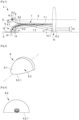
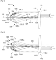
- the invention defined in claim 1, relates to a light device, in particular for a motor vehicle, comprising a light source capable of emitting light rays; a collector with a reflective surface configured to collect and reflect the light rays emitted by the light source; an optical system configured to project the light rays coming from the reflective surface into a light beam along an optical axis of the light device; remarkable in that the light device comprises a mirror configured to form a virtual image of the light source and the reflective surface of the collector, and the optical system is configured to form an image of said virtual image.
- the light source and the reflective surface form a light module.
- a light module is capable of forming a light beam.
- the light device may comprise several light modules. In the presence of a single light module, the light device is similar to the light module.
- the light device forms an autonomous assembly in that each of its components, such as for example the light source(s), the collector(s) and the optical system, is rigidly connected to the other components, in particular via a specific support (not detailed), and is thus optically positioned relative to the other components.
- One or more light devices may thus be arranged in a projector housing in order to perform, where appropriate in combination, all the regulatory lighting and signaling functions.
- the reflecting surface of the collector and the mirror are configured so that the light rays reflected by a rear part of said reflecting surface are parallel to the optical axis or have, in a vertical plane and relative to said axis, an angle of inclination less than or equal to 25°, preferably less than or equal to 10°.
- the mirror is flat and parallel to the optical axis or is inclined relative to said optical axis by an angle of less than 10°.
- the light source is configured to emit the light rays in a main direction perpendicular to the optical axis or inclined relative to a direction perpendicular to said optical axis by an angle of less than 25°.
- the reflecting surface of the collector has a parabolic or elliptical profile.
- it is a surface of revolution of said profile.
- the revolution is around an axis advantageously parallel to the optical axis.
- the reflecting surface is a free-form surface or a swept surface or an asymmetrical surface. It can also comprise several sectors.
- the mirror is formed on the collector.
- the light source is arranged on a substrate, the mirror being aligned with said substrate.
Landscapes
- Engineering & Computer Science (AREA)
- General Engineering & Computer Science (AREA)
- Physics & Mathematics (AREA)
- Microelectronics & Electronic Packaging (AREA)
- Optics & Photonics (AREA)
- Mechanical Engineering (AREA)
- Non-Portable Lighting Devices Or Systems Thereof (AREA)
Claims (17)
- Leuchtvorrichtung (2; 102) insbesondere für ein Kraftfahrzeug, umfassend:- eine Lichtquelle (4; 104), die geeignet ist, Lichtstrahlen abzugeben;- einen Kollektor (6; 106) mit einer reflektierenden Fläche (6.2; 106.2), die dazu ausgebildet ist, die Lichtstrahlen, die von der Lichtquelle (4; 104) abgegeben werden, zu sammeln und zu reflektieren;- ein Optiksystem (10; 110), das dazu ausgebildet ist, die Lichtstrahlen von der reflektierenden Fläche (6.2; 106.2) in einem Lichtbündel (12; 112) entlang einer optischen Achse der Leuchtvorrichtung (8; 108) zu projizieren;wobei die Leuchtvorrichtung (2; 102) einen Spiegel (7; 107) umfasst, der dazu ausgebildet ist, ein virtuelles Bild (4, 6.2; 104, 106.2) der Lichtquelle und der reflektierenden Fläche des Kollektors (6; 106) zu erzeugen, und das Optiksystem (10; 110) dazu ausgebildet ist, ein Bild des virtuellen Bilds (4, 6.2; 104, 106.2) zu erzeugen,dadurch gekennzeichnet, dass die reflektierende Fläche (6.2; 106.2) des Kollektors (6; 106) eine Hinterkante (6.2.1; 106.2.1) aufweist, wobei das Lichtbündel (12; 112) ein Bündel mit horizontaler Hell-Dunkel-Grenze ist, wobei die Hell-Dunkel-Grenze ein Bild der Hinterkante ist.
- Leuchtvorrichtung (2; 102) nach Anspruch 1, dadurch gekennzeichnet, dass die reflektierende Fläche (6.2; 106.2) des Kollektors (6; 106) und der Spiegel (7; 107) dazu ausgebildet sind, dass die Lichtstrahlen, die von einem hinteren Abschnitt der reflektierenden Fläche (6.2; 106.2) reflektiert werden, parallel zur optischen Achse (8, 108) verlaufen oder in einer vertikalen Ebene und im Verhältnis zu der Achse einen Neigungswinkel kleiner als oder gleich 25°, vorzugsweise kleiner als oder gleich 10° aufweisen.
- Leuchtvorrichtung (2; 102) nach einem der Ansprüche 1 und 2, dadurch gekennzeichnet, dass der Spiegel (7; 107) eben ist und parallel zur optischen Achse (8; 108) verläuft oder im Verhältnis zu der optischen Achse um einen Winkel kleiner als 10° geneigt ist.
- Leuchtvorrichtung (2; 102) nach einem der Ansprüche 1 bis 3, dadurch gekennzeichnet, dass die Lichtquelle (4; 104) dazu ausgebildet ist, die Lichtstrahlen in einer Hauptrichtung senkrecht zur optischen Achse (8; 108) oder im Verhältnis zu einer Richtung senkrecht zur optischen Achse um einen Winkel kleiner als 25° geneigt abzugeben.
- Leuchtvorrichtung (2; 102) nach einem der Ansprüche 1 bis 4, dadurch gekennzeichnet, dass die reflektierende Fläche (6.2; 106.2) des Kollektors (6; 106) ein parabolisches oder ellipsenförmiges Profil aufweist.
- Leuchtvorrichtung (2) nach einem der Ansprüche 1 bis 5, dadurch gekennzeichnet, dass sich der Spiegel (7) in einer Verlängerung der reflektierenden Fläche (6.2) des Kollektors (6) zum Optiksystem (10) hin erstreckt.
- Leuchtvorrichtung (2) nach einem der Ansprüche 1 bis 6, dadurch gekennzeichnet, dass die reflektierende Fläche (6.2) des Kollektors (2) dazu ausgebildet ist, die Lichtstrahlen, die von der Lichtquelle (4) abgegeben werden, in einer Hauptrichtung zu reflektieren, die von der optischen Achse (8) abweicht.
- Leuchtvorrichtung (2) nach Ansprüchen 6 und 7, dadurch gekennzeichnet, dass der Spiegel (7) in der Verlängerung der reflektierenden Fläche (6.2) des Kollektors (6) angeordnet ist.
- Leuchtvorrichtung (102) nach einem der Ansprüche 1 bis 5, dadurch gekennzeichnet, dass die Lichtquelle (104) auf einem Substrat (118) angeordnet ist, wobei der Spiegel (7) an dem Substrat (118) ausgerichtet ist.
- Leuchtvorrichtung (102) nach Anspruch 9, dadurch gekennzeichnet, dass die reflektierende Fläche (106.2) des Kollektors (6) dazu ausgebildet ist, die Lichtstrahlen, die von der Lichtquelle (104) abgegeben werden, in einer Hauptrichtung zu reflektieren, die mit der optischen Achse (108) konvergiert, wobei die optische Achse durch das Substrat (118) verläuft.
- Leuchtvorrichtung (2; 102) nach einem der Ansprüche 1 bis 10, dadurch gekennzeichnet, dass das Optiksystem (10; 110) einen Brennpunkt (10.3; 110.3) aufweist, der sich auf einem Bereich befindet, der sich zwischen dem virtuellen Bild (4; 104) der Lichtquelle (4; 104) und dem virtuellen Bild (6.2; 106.2) der reflektierenden Fläche (6.2; 106.2) befindet.
- Leuchtvorrichtung (2; 102) nach Anspruch 11, dadurch gekennzeichnet, dass sich der Brennpunkt (10.3; 110.3) des Optiksystems (10; 110) auf dem virtuellen Bild (6.2; 106.2) der reflektierenden Fläche (6.2; 106.2) hinten am virtuellen Bild (4; 104) der virtuellen Lichtquelle (4; 104) entlang der optischen Achse (8; 108) befindet.
- Leuchtvorrichtung (2; 102) nach einem der Ansprüche 11 und 12, dadurch gekennzeichnet, dass das Optiksystem eine Linse (10; 110) umfasst, die einem Sammellinsenabschnitt entspricht, der auf einer virtuellen optischen Achse (8; 108) zentriert ist, die parallel zur optischen Achse (8; 108) und durch den Brennpunkt (10.3; 110.3) des Optiksystems verläuft.
- Leuchtvorrichtung (2; 102) nach einem der Ansprüche 1 bis 13, dadurch gekennzeichnet, dass sich die Lichtquelle (4; 104) und der Kollektor (6; 106) oberhalb der optischen Achse (8; 108) befinden, wenn sich die Leuchtvorrichtung in Betriebsposition befindet, wobei die Hell-Dunkel-Grenze des Lichtbündels (12; 112) eine untere Hell-Dunkel-Grenze ist.
- Leuchtvorrichtung (2'; 102') nach einem der Ansprüche 1 bis 13, dadurch gekennzeichnet, dass sich die Lichtquelle (4; 104) und der Kollektor (6; 106) unterhalb der optischen Achse (8; 108) befinden, wenn sich die Leuchtvorrichtung in Betriebsposition befindet, wobei die Hell-Dunkel-Grenze des Lichtbündels (12'; 112') eine obere Hell-Dunkel-Grenze ist.
- Leuchtvorrichtung (2) nach einem der Ansprüche 1 bis 15, dadurch gekennzeichnet, dass die Leuchtvorrichtung (4; 104), der Kollektor (6; 106) und das Lichtbündel (12; 112) eine erste Lichtquelle, ein erster Kollektor bzw. ein erstes Lichtbündel sind, wobei die Leuchtvorrichtung eine zweite Lichtquelle (14) und einen zweiten Kollektor (16) mit einer reflektierenden Fläche umfasst, die dazu ausgebildet ist, die Lichtstrahlen, die von der zweiten Lichtquelle (14) abgegeben werden, zu sammeln und zu reflektieren, wobei das Optiksystem (10; 110) dazu ausgebildet ist, die Lichtstrahlen von der reflektierenden Fläche in einem zweiten Lichtbündel entlang einer optischen Achse der Vorrichtung und entsprechend einem Bild der reflektierenden Fläche zu projizieren.
- Leuchtvorrichtung nach Anspruch 16, dadurch gekennzeichnet, dass der erste Kollektor (6; 106) und die erste Lichtquelle (4; 104) bezogen auf die optische Achse (8; 108) dem zweiten Kollektor (16) bzw. der zweiten Lichtquelle (14) gegenüberliegen; oder der erste Kollektor und die erste Lichtquelle einerseits und der zweite Kollektor und die zweite Lichtquelle andererseits Seite an Seite angeordnet sind.
Applications Claiming Priority (2)
| Application Number | Priority Date | Filing Date | Title |
|---|---|---|---|
| FR1902615A FR3093788B1 (fr) | 2019-03-14 | 2019-03-14 | Dispositif lumineux imageant une surface eclairee virtuelle d’un collecteur |
| EP20158866.2A EP3708905B1 (de) | 2019-03-14 | 2020-02-21 | Beleuchtungsvorrichtung zur abbildung eines gespiegelten bilds eines kollektors |
Related Parent Applications (2)
| Application Number | Title | Priority Date | Filing Date |
|---|---|---|---|
| EP20158866.2A Division EP3708905B1 (de) | 2019-03-14 | 2020-02-21 | Beleuchtungsvorrichtung zur abbildung eines gespiegelten bilds eines kollektors |
| EP20158866.2A Division-Into EP3708905B1 (de) | 2019-03-14 | 2020-02-21 | Beleuchtungsvorrichtung zur abbildung eines gespiegelten bilds eines kollektors |
Publications (2)
| Publication Number | Publication Date |
|---|---|
| EP4134586A1 EP4134586A1 (de) | 2023-02-15 |
| EP4134586B1 true EP4134586B1 (de) | 2025-07-09 |
Family
ID=67383999
Family Applications (2)
| Application Number | Title | Priority Date | Filing Date |
|---|---|---|---|
| EP20158866.2A Active EP3708905B1 (de) | 2019-03-14 | 2020-02-21 | Beleuchtungsvorrichtung zur abbildung eines gespiegelten bilds eines kollektors |
| EP22198166.5A Active EP4134586B1 (de) | 2019-03-14 | 2020-02-21 | Beleuchtungsvorrichtung zur abbildung einer virtuellen beleuchteten oberfläche eines kollektors |
Family Applications Before (1)
| Application Number | Title | Priority Date | Filing Date |
|---|---|---|---|
| EP20158866.2A Active EP3708905B1 (de) | 2019-03-14 | 2020-02-21 | Beleuchtungsvorrichtung zur abbildung eines gespiegelten bilds eines kollektors |
Country Status (8)
| Country | Link |
|---|---|
| US (1) | US10920949B2 (de) |
| EP (2) | EP3708905B1 (de) |
| JP (1) | JP7515276B2 (de) |
| KR (1) | KR102841256B1 (de) |
| CN (2) | CN119123352A (de) |
| ES (1) | ES3042294T3 (de) |
| FR (1) | FR3093788B1 (de) |
| PL (1) | PL3708905T3 (de) |
Families Citing this family (5)
| Publication number | Priority date | Publication date | Assignee | Title |
|---|---|---|---|---|
| CN108473093B (zh) * | 2016-01-29 | 2021-10-22 | 金泰克斯公司 | 用于车辆照明模块的指示器光学 |
| FR3084728B1 (fr) * | 2018-07-31 | 2021-03-19 | Valeo Vision | Module lumineux imageant la surface eclairee d'un collecteur |
| FR3118127B1 (fr) * | 2020-12-18 | 2022-12-16 | Valeo Vision | Dispositif lumineux bi-fonction avec lentille rotative |
| FR3130011B1 (fr) * | 2021-12-07 | 2024-04-05 | Valeo Vision | Dispositif lumineux d’un véhicule automobile |
| US20250145081A1 (en) * | 2022-07-12 | 2025-05-08 | Muth Mirror Systems, Llc | Reflecting optic assembly |
Family Cites Families (32)
| Publication number | Priority date | Publication date | Assignee | Title |
|---|---|---|---|---|
| JPH02123605A (ja) * | 1988-11-01 | 1990-05-11 | Stanley Electric Co Ltd | 車両用信号灯具 |
| US5023758A (en) * | 1989-11-13 | 1991-06-11 | General Electric Company | Single arc discharge headlamp with light switch for high/low beam operation |
| FR2830073B1 (fr) * | 2001-09-27 | 2003-12-12 | Valeo Vision | Projecteur d'eclairage elliptique de vehicule automobile comportant un systeme optique secondaire |
| FR2839139B1 (fr) * | 2002-04-25 | 2005-01-14 | Valeo Vision | Module d'eclairage elliptique sans cache realisant un faisceau d'eclairage a coupure et projecteur comportant un tel module |
| JP2004349130A (ja) * | 2003-05-22 | 2004-12-09 | Koito Mfg Co Ltd | 車両用灯具 |
| FR2866411A1 (fr) * | 2004-02-13 | 2005-08-19 | Valeo Vision | Projecteur pour vehicule automobile comportant un reflecteur et un element de deviation optique |
| FR2858042B1 (fr) * | 2003-07-24 | 2005-09-23 | Valeo Vision | Module d'eclairage elliptique sans cache realisant un faisceau d'eclairage a coupure et projecteur comportant un tel module |
| JP4526256B2 (ja) * | 2003-10-17 | 2010-08-18 | スタンレー電気株式会社 | 光源モジュールおよび該光源モジュールを具備する灯具 |
| JP4108597B2 (ja) * | 2003-12-24 | 2008-06-25 | 株式会社小糸製作所 | 車両用灯具ユニット |
| JP4339143B2 (ja) * | 2004-02-10 | 2009-10-07 | 株式会社小糸製作所 | 車両用灯具ユニット |
| JP4563338B2 (ja) * | 2006-04-18 | 2010-10-13 | 株式会社小糸製作所 | 車両用前照灯の灯具ユニット |
| JP4458067B2 (ja) * | 2006-05-17 | 2010-04-28 | 市光工業株式会社 | 車両用灯具 |
| JP2008123753A (ja) * | 2006-11-09 | 2008-05-29 | Koito Mfg Co Ltd | 車両用灯具ユニット |
| JP2009259468A (ja) * | 2008-04-14 | 2009-11-05 | Ichikoh Ind Ltd | 車両用灯具 |
| JP5281359B2 (ja) * | 2008-10-30 | 2013-09-04 | 株式会社小糸製作所 | 車両用灯具ユニット及び車両用灯具 |
| FR2940403B1 (fr) * | 2008-12-19 | 2014-01-17 | Valeo Vision Sas | Dispositif d'eclairage pour projecteur de vehicule assurant plusieurs fonctions d'eclairage ou une fonction variable avec une seule source lumineuse |
| JP5423159B2 (ja) * | 2009-06-04 | 2014-02-19 | スタンレー電気株式会社 | 車両用灯具 |
| AT510454B1 (de) * | 2010-10-14 | 2013-04-15 | Zizala Lichtsysteme Gmbh | Led-fahrzeugscheinwerfer |
| JP2012160356A (ja) * | 2011-02-01 | 2012-08-23 | Stanley Electric Co Ltd | 車両用灯具 |
| DE102011013211B4 (de) * | 2011-03-05 | 2012-12-06 | Automotive Lighting Reutlingen Gmbh | Kraftfahrzeugscheinwerfer mit einem Mehrfunktions-Projektionsmodul |
| JP5640306B2 (ja) * | 2011-03-14 | 2014-12-17 | スタンレー電気株式会社 | 灯具ユニット |
| US8939627B2 (en) * | 2011-07-29 | 2015-01-27 | Stanley Electric Co., Ltd. | Vehicle lighting unit |
| JP5879065B2 (ja) * | 2011-07-29 | 2016-03-08 | スタンレー電気株式会社 | 車両用前照灯 |
| JP5830294B2 (ja) * | 2011-07-29 | 2015-12-09 | スタンレー電気株式会社 | 車両用前照灯 |
| DE102012202290B4 (de) * | 2012-02-15 | 2014-03-27 | Automotive Lighting Reutlingen Gmbh | Lichtmodul für ein blendungsfreies Kraftfahrzeug-Fernlicht |
| WO2013132530A1 (ja) * | 2012-03-06 | 2013-09-12 | 三菱電機株式会社 | 前照灯用光源および前照灯 |
| DE102013207845A1 (de) * | 2013-04-29 | 2014-10-30 | Automotive Lighting Reutlingen Gmbh | Lichtmodul für einen Kraftfahrzeugscheinwerfer |
| KR102289755B1 (ko) * | 2014-12-24 | 2021-08-13 | 에스엘 주식회사 | 헤드 램프용 로우빔 쉴드 |
| FR3038695A1 (fr) * | 2015-07-10 | 2017-01-13 | Valeo Vision | Module lumineux pour l'eclairage et/ou la signalisation d'un vehicule automobile |
| FR3039630A1 (fr) * | 2015-07-28 | 2017-02-03 | Valeo Vision | Systeme d'eclairage pour projecteur de vehicule automobile |
| FR3047541B1 (fr) | 2015-12-10 | 2019-10-04 | Valeo Vision | Module d'eclairage automobile avec fonctions code et route combinees et une source lumineuse ajustable |
| FR3063795B1 (fr) * | 2017-03-13 | 2019-04-05 | Valeo Vision | Dispositif lumineux, notamment d'eclairage et/ou de signalisation, pour vehicule automobile |
-
2019
- 2019-03-14 FR FR1902615A patent/FR3093788B1/fr not_active Expired - Fee Related
-
2020
- 2020-02-21 ES ES22198166T patent/ES3042294T3/es active Active
- 2020-02-21 PL PL20158866.2T patent/PL3708905T3/pl unknown
- 2020-02-21 EP EP20158866.2A patent/EP3708905B1/de active Active
- 2020-02-21 EP EP22198166.5A patent/EP4134586B1/de active Active
- 2020-03-11 US US16/815,272 patent/US10920949B2/en active Active
- 2020-03-12 KR KR1020200030690A patent/KR102841256B1/ko active Active
- 2020-03-13 JP JP2020044463A patent/JP7515276B2/ja active Active
- 2020-03-13 CN CN202410787963.4A patent/CN119123352A/zh active Pending
- 2020-03-13 CN CN202010176786.8A patent/CN111692568B/zh active Active
Also Published As
| Publication number | Publication date |
|---|---|
| CN111692568A (zh) | 2020-09-22 |
| PL3708905T3 (pl) | 2023-03-13 |
| CN111692568B (zh) | 2024-07-05 |
| KR102841256B1 (ko) | 2025-07-31 |
| ES3042294T3 (en) | 2025-11-19 |
| EP4134586A1 (de) | 2023-02-15 |
| CN119123352A (zh) | 2024-12-13 |
| FR3093788A1 (fr) | 2020-09-18 |
| FR3093788B1 (fr) | 2022-05-27 |
| EP3708905B1 (de) | 2022-11-09 |
| US10920949B2 (en) | 2021-02-16 |
| JP2020149976A (ja) | 2020-09-17 |
| JP7515276B2 (ja) | 2024-07-12 |
| US20200292144A1 (en) | 2020-09-17 |
| KR20200110215A (ko) | 2020-09-23 |
| EP3708905A1 (de) | 2020-09-16 |
Similar Documents
| Publication | Publication Date | Title |
|---|---|---|
| EP3708904B1 (de) | Leuchtvorrichtung, die die beleuchteten flächen von mindestens zwei kollektoren abbildet | |
| EP4134586B1 (de) | Beleuchtungsvorrichtung zur abbildung einer virtuellen beleuchteten oberfläche eines kollektors | |
| EP3830474A1 (de) | Leuchtmodul zur abbildung der beleuchteten fläche eines kollektors | |
| EP2743567B1 (de) | Optisches hauptelement, beleuchtungsmodul und scheinwerfer für kraftfahrzeug | |
| EP1528312B1 (de) | Beleuchtungsmodul für Kfz-Scheinwerfer | |
| EP4062098B1 (de) | Kombiniertes leuchtmodul zur abbildung der beleuchteten fläche eines kollektors | |
| EP3232118A1 (de) | Scheinwerfer für ein kraftfahrzeug | |
| EP1500869A1 (de) | Elliptische Beleuchtungseinheit ohne Lichtblende zur Erzeugung eines Abblendlichtbündels und Scheinwerfer mit einer derartigen Belleuchtungseinheit | |
| FR2853393A1 (fr) | Phare de vehicule a diode photoemissive | |
| EP4264120A1 (de) | Kraftfahrzeugscheinwerfer mit mehreren beleuchtungsmodulen auf einer geneigten gemeinsamen platte | |
| WO2023031341A1 (fr) | Dispositif lumineux d'un véhicule automobile | |
| EP3505813B1 (de) | Leuchtmodul zum schwenken des lichstrahls, insbesondere für kraftfahrzeug, das mit einem fokalisierungssystem reduzierter grösse ausgestattet ist, und leuchtvorrichtung eines kraftfahrzeugs, die ein solches leuchtmodul umfasst | |
| WO2022129420A1 (fr) | Module lumineux imageant la surface eclairee d'un collecteur avec bloqueur de rayons parasites | |
| EP4285051B1 (de) | Kraftfahrzeugvorrichtung zur beleuchtung der strasse | |
| FR3130011A1 (fr) | Dispositif lumineux d’un véhicule automobile | |
| EP4264123B1 (de) | Beleuchtungsvorrichtung mit doppelfunktion und rotierender linse | |
| EP2302292A1 (de) | Optisches Modul mit Falzmaschine, das aus einem Diopter für transparentes Material/Luft gebildet wird | |
| EP4569262A1 (de) | Scheinwerfer mit vertikaler hell-dunkel-grenze und verlängerung für ein kraftfahrzeug | |
| FR3133901A1 (fr) | Module lumineux imageant la surface éclairée d’un collecteur avec bloqueur de rayons parasites extrudé | |
| EP3276249A1 (de) | Leuchtsystem für beleuchtungsvorrichtung und/oder signalvorrichtung für kraftfahrzeug |
Legal Events
| Date | Code | Title | Description |
|---|---|---|---|
| PUAI | Public reference made under article 153(3) epc to a published international application that has entered the european phase |
Free format text: ORIGINAL CODE: 0009012 |
|
| STAA | Information on the status of an ep patent application or granted ep patent |
Free format text: STATUS: THE APPLICATION HAS BEEN PUBLISHED |
|
| AC | Divisional application: reference to earlier application |
Ref document number: 3708905 Country of ref document: EP Kind code of ref document: P |
|
| AK | Designated contracting states |
Kind code of ref document: A1 Designated state(s): AL AT BE BG CH CY CZ DE DK EE ES FI FR GB GR HR HU IE IS IT LI LT LU LV MC MK MT NL NO PL PT RO RS SE SI SK SM TR |
|
| STAA | Information on the status of an ep patent application or granted ep patent |
Free format text: STATUS: REQUEST FOR EXAMINATION WAS MADE |
|
| 17P | Request for examination filed |
Effective date: 20231114 |
|
| RBV | Designated contracting states (corrected) |
Designated state(s): AL AT BE BG CH CY CZ DE DK EE ES FI FR GB GR HR HU IE IS IT LI LT LU LV MC MK MT NL NO PL PT RO RS SE SI SK SM TR |
|
| GRAP | Despatch of communication of intention to grant a patent |
Free format text: ORIGINAL CODE: EPIDOSNIGR1 |
|
| STAA | Information on the status of an ep patent application or granted ep patent |
Free format text: STATUS: GRANT OF PATENT IS INTENDED |
|
| RIC1 | Information provided on ipc code assigned before grant |
Ipc: F21S 41/25 20180101ALI20250116BHEP Ipc: F21S 41/32 20180101ALI20250116BHEP Ipc: F21S 41/365 20180101ALI20250116BHEP Ipc: F21S 41/255 20180101ALI20250116BHEP Ipc: F21S 41/148 20180101ALI20250116BHEP Ipc: F21S 41/147 20180101ALI20250116BHEP Ipc: F21S 41/33 20180101AFI20250116BHEP |
|
| INTG | Intention to grant announced |
Effective date: 20250203 |
|
| GRAS | Grant fee paid |
Free format text: ORIGINAL CODE: EPIDOSNIGR3 |
|
| GRAA | (expected) grant |
Free format text: ORIGINAL CODE: 0009210 |
|
| STAA | Information on the status of an ep patent application or granted ep patent |
Free format text: STATUS: THE PATENT HAS BEEN GRANTED |
|
| AC | Divisional application: reference to earlier application |
Ref document number: 3708905 Country of ref document: EP Kind code of ref document: P |
|
| AK | Designated contracting states |
Kind code of ref document: B1 Designated state(s): AL AT BE BG CH CY CZ DE DK EE ES FI FR GB GR HR HU IE IS IT LI LT LU LV MC MK MT NL NO PL PT RO RS SE SI SK SM TR |
|
| REG | Reference to a national code |
Ref country code: GB Ref legal event code: FG4D Free format text: NOT ENGLISH |
|
| REG | Reference to a national code |
Ref country code: CH Ref legal event code: EP |
|
| REG | Reference to a national code |
Ref country code: IE Ref legal event code: FG4D Free format text: LANGUAGE OF EP DOCUMENT: FRENCH |
|
| REG | Reference to a national code |
Ref country code: DE Ref legal event code: R096 Ref document number: 602020054443 Country of ref document: DE |
|
| REG | Reference to a national code |
Ref country code: NL Ref legal event code: MP Effective date: 20250709 |
|
| REG | Reference to a national code |
Ref country code: ES Ref legal event code: FG2A Ref document number: 3042294 Country of ref document: ES Kind code of ref document: T3 Effective date: 20251119 |
|
| PG25 | Lapsed in a contracting state [announced via postgrant information from national office to epo] |
Ref country code: PT Free format text: LAPSE BECAUSE OF FAILURE TO SUBMIT A TRANSLATION OF THE DESCRIPTION OR TO PAY THE FEE WITHIN THE PRESCRIBED TIME-LIMIT Effective date: 20251110 |
|
| PG25 | Lapsed in a contracting state [announced via postgrant information from national office to epo] |
Ref country code: NL Free format text: LAPSE BECAUSE OF FAILURE TO SUBMIT A TRANSLATION OF THE DESCRIPTION OR TO PAY THE FEE WITHIN THE PRESCRIBED TIME-LIMIT Effective date: 20250709 |