EP4134559B1 - Selbstschmierende lineare führungsbuchsen für sich hin- und herbewegende dosen- und flaschenabfüllmaschinen - Google Patents
Selbstschmierende lineare führungsbuchsen für sich hin- und herbewegende dosen- und flaschenabfüllmaschinen Download PDFInfo
- Publication number
- EP4134559B1 EP4134559B1 EP22188963.7A EP22188963A EP4134559B1 EP 4134559 B1 EP4134559 B1 EP 4134559B1 EP 22188963 A EP22188963 A EP 22188963A EP 4134559 B1 EP4134559 B1 EP 4134559B1
- Authority
- EP
- European Patent Office
- Prior art keywords
- linear guide
- bushing
- self
- guide mechanism
- liner
- Prior art date
- Legal status (The legal status is an assumption and is not a legal conclusion. Google has not performed a legal analysis and makes no representation as to the accuracy of the status listed.)
- Active
Links
Images


Classifications
-
- F—MECHANICAL ENGINEERING; LIGHTING; HEATING; WEAPONS; BLASTING
- F16—ENGINEERING ELEMENTS AND UNITS; GENERAL MEASURES FOR PRODUCING AND MAINTAINING EFFECTIVE FUNCTIONING OF MACHINES OR INSTALLATIONS; THERMAL INSULATION IN GENERAL
- F16C—SHAFTS; FLEXIBLE SHAFTS; ELEMENTS OR CRANKSHAFT MECHANISMS; ROTARY BODIES OTHER THAN GEARING ELEMENTS; BEARINGS
- F16C29/00—Bearings for parts moving only linearly
- F16C29/02—Sliding-contact bearings
-
- F—MECHANICAL ENGINEERING; LIGHTING; HEATING; WEAPONS; BLASTING
- F16—ENGINEERING ELEMENTS AND UNITS; GENERAL MEASURES FOR PRODUCING AND MAINTAINING EFFECTIVE FUNCTIONING OF MACHINES OR INSTALLATIONS; THERMAL INSULATION IN GENERAL
- F16C—SHAFTS; FLEXIBLE SHAFTS; ELEMENTS OR CRANKSHAFT MECHANISMS; ROTARY BODIES OTHER THAN GEARING ELEMENTS; BEARINGS
- F16C17/00—Sliding-contact bearings for exclusively rotary movement
- F16C17/02—Sliding-contact bearings for exclusively rotary movement for radial load only
-
- F—MECHANICAL ENGINEERING; LIGHTING; HEATING; WEAPONS; BLASTING
- F16—ENGINEERING ELEMENTS AND UNITS; GENERAL MEASURES FOR PRODUCING AND MAINTAINING EFFECTIVE FUNCTIONING OF MACHINES OR INSTALLATIONS; THERMAL INSULATION IN GENERAL
- F16C—SHAFTS; FLEXIBLE SHAFTS; ELEMENTS OR CRANKSHAFT MECHANISMS; ROTARY BODIES OTHER THAN GEARING ELEMENTS; BEARINGS
- F16C33/00—Parts of bearings; Special methods for making bearings or parts thereof
- F16C33/02—Parts of sliding-contact bearings
- F16C33/04—Brasses; Bushes; Linings
- F16C33/06—Sliding surface mainly made of metal
- F16C33/08—Attachment of brasses, bushes or linings to the bearing housing
-
- F—MECHANICAL ENGINEERING; LIGHTING; HEATING; WEAPONS; BLASTING
- F16—ENGINEERING ELEMENTS AND UNITS; GENERAL MEASURES FOR PRODUCING AND MAINTAINING EFFECTIVE FUNCTIONING OF MACHINES OR INSTALLATIONS; THERMAL INSULATION IN GENERAL
- F16C—SHAFTS; FLEXIBLE SHAFTS; ELEMENTS OR CRANKSHAFT MECHANISMS; ROTARY BODIES OTHER THAN GEARING ELEMENTS; BEARINGS
- F16C33/00—Parts of bearings; Special methods for making bearings or parts thereof
- F16C33/02—Parts of sliding-contact bearings
- F16C33/04—Brasses; Bushes; Linings
- F16C33/06—Sliding surface mainly made of metal
- F16C33/10—Construction relative to lubrication
- F16C33/1095—Construction relative to lubrication with solids as lubricant, e.g. dry coatings, powder
-
- F—MECHANICAL ENGINEERING; LIGHTING; HEATING; WEAPONS; BLASTING
- F16—ENGINEERING ELEMENTS AND UNITS; GENERAL MEASURES FOR PRODUCING AND MAINTAINING EFFECTIVE FUNCTIONING OF MACHINES OR INSTALLATIONS; THERMAL INSULATION IN GENERAL
- F16C—SHAFTS; FLEXIBLE SHAFTS; ELEMENTS OR CRANKSHAFT MECHANISMS; ROTARY BODIES OTHER THAN GEARING ELEMENTS; BEARINGS
- F16C33/00—Parts of bearings; Special methods for making bearings or parts thereof
- F16C33/02—Parts of sliding-contact bearings
- F16C33/04—Brasses; Bushes; Linings
- F16C33/06—Sliding surface mainly made of metal
- F16C33/12—Structural composition; Use of special materials or surface treatments, e.g. for rust-proofing
- F16C33/122—Multilayer structures of sleeves, washers or liners
- F16C33/124—Details of overlays
-
- F—MECHANICAL ENGINEERING; LIGHTING; HEATING; WEAPONS; BLASTING
- F16—ENGINEERING ELEMENTS AND UNITS; GENERAL MEASURES FOR PRODUCING AND MAINTAINING EFFECTIVE FUNCTIONING OF MACHINES OR INSTALLATIONS; THERMAL INSULATION IN GENERAL
- F16C—SHAFTS; FLEXIBLE SHAFTS; ELEMENTS OR CRANKSHAFT MECHANISMS; ROTARY BODIES OTHER THAN GEARING ELEMENTS; BEARINGS
- F16C33/00—Parts of bearings; Special methods for making bearings or parts thereof
- F16C33/02—Parts of sliding-contact bearings
- F16C33/04—Brasses; Bushes; Linings
- F16C33/20—Sliding surface consisting mainly of plastics
- F16C33/201—Composition of the plastic
-
- F—MECHANICAL ENGINEERING; LIGHTING; HEATING; WEAPONS; BLASTING
- F16—ENGINEERING ELEMENTS AND UNITS; GENERAL MEASURES FOR PRODUCING AND MAINTAINING EFFECTIVE FUNCTIONING OF MACHINES OR INSTALLATIONS; THERMAL INSULATION IN GENERAL
- F16C—SHAFTS; FLEXIBLE SHAFTS; ELEMENTS OR CRANKSHAFT MECHANISMS; ROTARY BODIES OTHER THAN GEARING ELEMENTS; BEARINGS
- F16C33/00—Parts of bearings; Special methods for making bearings or parts thereof
- F16C33/02—Parts of sliding-contact bearings
- F16C33/04—Brasses; Bushes; Linings
- F16C33/20—Sliding surface consisting mainly of plastics
- F16C33/203—Multilayer structures, e.g. sleeves comprising a plastic lining
- F16C33/205—Multilayer structures, e.g. sleeves comprising a plastic lining with two layers
-
- F—MECHANICAL ENGINEERING; LIGHTING; HEATING; WEAPONS; BLASTING
- F16—ENGINEERING ELEMENTS AND UNITS; GENERAL MEASURES FOR PRODUCING AND MAINTAINING EFFECTIVE FUNCTIONING OF MACHINES OR INSTALLATIONS; THERMAL INSULATION IN GENERAL
- F16C—SHAFTS; FLEXIBLE SHAFTS; ELEMENTS OR CRANKSHAFT MECHANISMS; ROTARY BODIES OTHER THAN GEARING ELEMENTS; BEARINGS
- F16C33/00—Parts of bearings; Special methods for making bearings or parts thereof
- F16C33/02—Parts of sliding-contact bearings
- F16C33/04—Brasses; Bushes; Linings
- F16C33/28—Brasses; Bushes; Linings with embedded reinforcements shaped as frames or meshed materials
-
- B—PERFORMING OPERATIONS; TRANSPORTING
- B33—ADDITIVE MANUFACTURING TECHNOLOGY
- B33Y—ADDITIVE MANUFACTURING, i.e. MANUFACTURING OF THREE-DIMENSIONAL [3-D] OBJECTS BY ADDITIVE DEPOSITION, ADDITIVE AGGLOMERATION OR ADDITIVE LAYERING, e.g. BY 3-D PRINTING, STEREOLITHOGRAPHY OR SELECTIVE LASER SINTERING
- B33Y80/00—Products made by additive manufacturing
-
- F—MECHANICAL ENGINEERING; LIGHTING; HEATING; WEAPONS; BLASTING
- F16—ENGINEERING ELEMENTS AND UNITS; GENERAL MEASURES FOR PRODUCING AND MAINTAINING EFFECTIVE FUNCTIONING OF MACHINES OR INSTALLATIONS; THERMAL INSULATION IN GENERAL
- F16C—SHAFTS; FLEXIBLE SHAFTS; ELEMENTS OR CRANKSHAFT MECHANISMS; ROTARY BODIES OTHER THAN GEARING ELEMENTS; BEARINGS
- F16C2202/00—Solid materials defined by their properties
- F16C2202/50—Lubricating properties
-
- F—MECHANICAL ENGINEERING; LIGHTING; HEATING; WEAPONS; BLASTING
- F16—ENGINEERING ELEMENTS AND UNITS; GENERAL MEASURES FOR PRODUCING AND MAINTAINING EFFECTIVE FUNCTIONING OF MACHINES OR INSTALLATIONS; THERMAL INSULATION IN GENERAL
- F16C—SHAFTS; FLEXIBLE SHAFTS; ELEMENTS OR CRANKSHAFT MECHANISMS; ROTARY BODIES OTHER THAN GEARING ELEMENTS; BEARINGS
- F16C2208/00—Plastics; Synthetic resins, e.g. rubbers
- F16C2208/02—Plastics; Synthetic resins, e.g. rubbers comprising fillers, fibres
- F16C2208/04—Glass fibres
-
- F—MECHANICAL ENGINEERING; LIGHTING; HEATING; WEAPONS; BLASTING
- F16—ENGINEERING ELEMENTS AND UNITS; GENERAL MEASURES FOR PRODUCING AND MAINTAINING EFFECTIVE FUNCTIONING OF MACHINES OR INSTALLATIONS; THERMAL INSULATION IN GENERAL
- F16C—SHAFTS; FLEXIBLE SHAFTS; ELEMENTS OR CRANKSHAFT MECHANISMS; ROTARY BODIES OTHER THAN GEARING ELEMENTS; BEARINGS
- F16C2208/00—Plastics; Synthetic resins, e.g. rubbers
- F16C2208/20—Thermoplastic resins
- F16C2208/30—Fluoropolymers
- F16C2208/32—Polytetrafluorethylene [PTFE]
-
- F—MECHANICAL ENGINEERING; LIGHTING; HEATING; WEAPONS; BLASTING
- F16—ENGINEERING ELEMENTS AND UNITS; GENERAL MEASURES FOR PRODUCING AND MAINTAINING EFFECTIVE FUNCTIONING OF MACHINES OR INSTALLATIONS; THERMAL INSULATION IN GENERAL
- F16C—SHAFTS; FLEXIBLE SHAFTS; ELEMENTS OR CRANKSHAFT MECHANISMS; ROTARY BODIES OTHER THAN GEARING ELEMENTS; BEARINGS
- F16C2208/00—Plastics; Synthetic resins, e.g. rubbers
- F16C2208/20—Thermoplastic resins
- F16C2208/40—Imides, e.g. polyimide [PI], polyetherimide [PEI]
-
- F—MECHANICAL ENGINEERING; LIGHTING; HEATING; WEAPONS; BLASTING
- F16—ENGINEERING ELEMENTS AND UNITS; GENERAL MEASURES FOR PRODUCING AND MAINTAINING EFFECTIVE FUNCTIONING OF MACHINES OR INSTALLATIONS; THERMAL INSULATION IN GENERAL
- F16C—SHAFTS; FLEXIBLE SHAFTS; ELEMENTS OR CRANKSHAFT MECHANISMS; ROTARY BODIES OTHER THAN GEARING ELEMENTS; BEARINGS
- F16C2208/00—Plastics; Synthetic resins, e.g. rubbers
- F16C2208/20—Thermoplastic resins
- F16C2208/70—Polyesters, e.g. polyethylene-terephthlate [PET], polybutylene-terephthlate [PBT]
-
- F—MECHANICAL ENGINEERING; LIGHTING; HEATING; WEAPONS; BLASTING
- F16—ENGINEERING ELEMENTS AND UNITS; GENERAL MEASURES FOR PRODUCING AND MAINTAINING EFFECTIVE FUNCTIONING OF MACHINES OR INSTALLATIONS; THERMAL INSULATION IN GENERAL
- F16C—SHAFTS; FLEXIBLE SHAFTS; ELEMENTS OR CRANKSHAFT MECHANISMS; ROTARY BODIES OTHER THAN GEARING ELEMENTS; BEARINGS
- F16C2208/00—Plastics; Synthetic resins, e.g. rubbers
- F16C2208/80—Thermosetting resins
- F16C2208/90—Phenolic resin
-
- F—MECHANICAL ENGINEERING; LIGHTING; HEATING; WEAPONS; BLASTING
- F16—ENGINEERING ELEMENTS AND UNITS; GENERAL MEASURES FOR PRODUCING AND MAINTAINING EFFECTIVE FUNCTIONING OF MACHINES OR INSTALLATIONS; THERMAL INSULATION IN GENERAL
- F16C—SHAFTS; FLEXIBLE SHAFTS; ELEMENTS OR CRANKSHAFT MECHANISMS; ROTARY BODIES OTHER THAN GEARING ELEMENTS; BEARINGS
- F16C2300/00—Application independent of particular apparatuses
- F16C2300/20—Application independent of particular apparatuses related to type of movement
- F16C2300/28—Reciprocating movement
-
- F—MECHANICAL ENGINEERING; LIGHTING; HEATING; WEAPONS; BLASTING
- F16—ENGINEERING ELEMENTS AND UNITS; GENERAL MEASURES FOR PRODUCING AND MAINTAINING EFFECTIVE FUNCTIONING OF MACHINES OR INSTALLATIONS; THERMAL INSULATION IN GENERAL
- F16C—SHAFTS; FLEXIBLE SHAFTS; ELEMENTS OR CRANKSHAFT MECHANISMS; ROTARY BODIES OTHER THAN GEARING ELEMENTS; BEARINGS
- F16C2300/00—Application independent of particular apparatuses
- F16C2300/40—Application independent of particular apparatuses related to environment, i.e. operating conditions
Definitions
- the present disclosure relates generally to a linear guide mechanism for a reciprocating container forming apparatus, and more particularly, to a self-lubricating linear guide bushing for reciprocating canning and bottling machinery.
- Canning and bottling machinery in the food and beverage industry utilize a rotating carousel that includes multiple housings secured thereto, each of which has a ram (e.g., shaft) with one or more cam-followers attached thereto.
- the carousel, the housings and the cam-followers rotate around a stationary cam that engages each of the cam-followers.
- the rotation of the carousel causes the cam-followers to transmit the rotary motion into linear sliding rams.
- These rams move at high speed and perform various forming functions on aluminum, tin, plastic, composites, polymers, or steel.
- the guide bushings are in place to guide each ram through its stroke and to keep the ram concentric with the housing.
- Such operation involves high friction between the ram and housing, which generates heat, wear, or slop.
- Some bushings according the conventional art wear 0.125 inches or more in a six-month period and need to be replaced due to loss of concentricity with the shaft.
- Rams according to the conventional art rely on greased bronze for reducing friction and wear. However, the greases can contaminate the containers that the food or beverages are contained in.
- bronze bushings are relatively heavy and require significant power dissipation of the machinery in use.
- alternatives to bronze bushings cannot withstand high-speed sliding interfaces and high temperatures generated by the sliding. The high-speed sliding can lead to overheating and premature failure of bushings.
- AT 280 823 B discloses a linear guide mechanism according to the preamble of claim 1.
- the linear guide mechanism for a reciprocating container forming apparatus.
- the linear guide mechanism includes a housing having an inside housing surface that defines a bore extending through the housing coaxial with a longitudinal axis.
- a shaft is disposed at least partially in the bore and is reciprocatably (i.e., back and forth oscillatory motion) and linearly moveable in the bore along the longitudinal axis.
- the shaft has an exterior shaft surface.
- a self-lubricating liner is disposed in the bore between the inside housing surface and the exterior shaft surface.
- the self-lubricating liner has an inside liner surface that is in sliding engagement with the exterior shaft surface of the shaft.
- the self-lubricating liner has an exterior liner surface and the linear guide mechanism comprises another self-lubricating liner spaced apart from the self-lubricating liner.
- the self-lubricating liner is adhered to the inside housing surface.
- the linear guide mechanism further includes a bushing disposed in the bore.
- the bushing has an exterior bushing surface and an inside bushing surface.
- the exterior bushing surface is secured to the inside housing surface.
- the exterior liner surface is secured to the inside bushing surface.
- the self-lubricating liner has an annular configuration. In some embodiments, the bushing has an annular configuration.
- the self-lubricating liner has a dynamic coefficient of friction of 0.02 to 0.06 when contact pressure between the inside liner surface and the exterior shaft surface is less than 2 ksi (i.e., kilopounds per square inch) and a relative speed between the inside liner surface and the exterior shaft surface are up to 30 to 100 inches per second. In some embodiments, the self-lubricating liner is configured to withstand temperatures of up to 200 to 300 degrees Fahrenheit.
- the self-lubricating liner includes polytetrafluoroethylene mono-filament fibers interwoven with support fibers encapsulated in a resin.
- the support fibers are selected from the group consisting of fiberglass, Dacron ® , polyester, cotton, Nomex ® , Kevlar ® and combinations thereof.
- the resin is selected from the group consisting of polyester, epoxy, phenolic, urethane, polyimide, polyamide, acrylics, cyanoacrylates, silicones, polysulfides, anaerobics, and elastomeric adhesives.
- the self-lubricating liner has a predetermined axial length configured to maintain the contact pressure between the inside liner surface and the exterior shaft surface at less than 2 ksi.
- the linear guide mechanism further includes another self-lubricating liner spaced apart from the self-lubricating liner. In some embodiments, the linear guide mechanism further includes another bushing spaced apart from the bushing. In some embodiments, the bushing includes at least one of an aluminum alloy, a titanium alloy, a bronze alloy, a beryllium alloy, and a magnesium alloy. In some embodiments, the bushing includes a lattice or honeycomb structure. In some embodiments, the lattice or honeycomb structure is manufactured by a three-dimensional (3D) printing process. In some embodiments, the bushing includes a groove extending axially along the inside bushing surface and radially outward towards the exterior bushing surface.
- 3D three-dimensional
- the groove radially terminates between the inside bushing surface and the exterior bushing surface. In some embodiments, the groove extends into the self-lubricating liner. In some embodiments, the groove is configured to receive an anti-rotation device. In some embodiments, the groove is configured to convey a coolant medium. In some embodiments, the self-lubricating liner is configured to sustain wear of less than seven thousandths of an inch after continuous linear sliding operation of the shaft in the self-lubricating liner for one year.
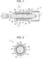
- a linear guide mechanism 10 for a reciprocating container forming apparatus includes a housing 12 having an inside housing surface 12E that defines a bore 12H extending through the housing 12 coaxial with a longitudinal axis L.
- a shaft 30 is disposed at least partially inside the bore 12H and is reciprocatably (i.e., back and forth oscillatory motion) and linearly moveable in the bore 12H along the longitudinal axis L.
- the shaft 30 has an exterior shaft surface 30E.
- Two self-lubricating liners 40 are disposed in the bore 12H between the inside housing surface 12E and the exterior shaft surface 30E.
- the self-lubricating liners 40 are spaced apart from each other.
- Each self-lubricating liner 40 has an inside liner surface 40E that is in sliding engagement with the exterior shaft surface 30E of the shaft 30.
- Each self-lubricating liner 40 has an exterior liner surface 40F. In other embodiments, there are more than two self-lubricating liners 40.
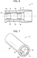
- the linear guide mechanism 10 further includes a bushing 20, which has an annular configuration and is disposed in the bore 12H.
- the bushing 20 has an exterior bushing surface 20F and an inside bushing surface 20E.
- the exterior bushing surface 20F is secured to the inside housing surface 12E.
- the exterior liner surface 40F is secured to the inside bushing surface 20E.
- the bushing 20 is press fit into the housing 12.
- each axial end of the bushing 20 is axially aligned with an axial end of a respective self-lubricating liner 40.
- the self-lubricating liners 40 are disposed entirely inside the bushing 20.
- the position of the self-lubricating liners 40 as shown in Figs. 1-3A is advantageous for maintaining functional stiffness of the bushing 20 for alignment and positional tolerance, while serving to reduce the frictional drag on the shaft 30.
- the surface area of the inside liner surface 40E influences the contact pressures experienced by the self-lubricating liners 40.
- the linear guide mechanism 10 includes two bushings 20 spaced apart from one another.
- the bushings 20 and the self-lubricating liners 40 are of the same length.
- one of the bushings 20 is axially aligned with one of the self-lubricating liners 40, and the other bushing 20 is axially aligned with the other self-lubricating liner 40.
- more than two bushings 20 spaced apart from one another are used.
- Some embodiments of the linear guide mechanism 10 lacks the bushing 20.
- the self-lubricating liner 40 is adhered directly to the inside housing surface 12E.
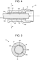
- the bushing 20 has a groove 20G extending axially along the inside bushing surface 20E and radially outward towards the exterior bushing surface 20F.
- the groove 20G radially terminates between the inside bushing surface 20E and the exterior bushing surface 20F.
- the groove 20G has rounded ends.
- the groove 20G extends into the self-lubricating liner 40.
- the groove 20G is configured to receive an anti-rotation device.
- the groove 20G is a keyway used for an anti-rotation device to keep the shaft 30 from rotating in the housing 12.
- the groove 20G is configured to convey a fluid such as a coolant medium or lubricant.
- the bushing 20 also has a lip 20L for receiving or compressing a seal.
- the self-lubricating liner 40 is able to withstand heat generated from loading and movement conditions.
- the self-lubricating liner 40 includes polytetrafluoroethylene mono-filament fibers 80A, 80B interwoven with support fibers 80C, 80D encapsulated in a resin 84.
- the polytetrafluoroethylene mono-filament fibers 80A, 80B include micro, nano, etched, or Torey ® flock fibers cut at 0.1mm-6mm lengths.
- the support fibers 80C, 80D include fiberglass, Dacron ® , polyester, cotton, Nomex ® , Kevlar ® , or combinations thereof.
- the resin 84 includes polyester, epoxy, phenolic, urethane, polyimide, polyamide, acrylics, cyanoacrylates, silicones, polysulfides, anaerobics, elastomeric adhesives, or other suitable resins.
- the self-lubricating liner 40 includes additives for enhancing composite performance.
- the self-lubricating liner 40 has a predetermined axial length configured to maintain contact pressure between the inside liner surface 40E and the exterior shaft surface 30E at less than 2 ksi. In some embodiments, the self-lubricating liner 40 has a radial thickness of 0.010-0.040 inches in the original as installed state, before operation. In some embodiments, the self-lubricating liner 40 has a dynamic coefficient of friction of 0.02 to 0.06 when contact pressure between the inside liner surface 40E and the exterior shaft surface 30E is less than 2 ksi and a relative speed between the inside liner surface 40E and the exterior shaft surface 30E is 30 to 100 inches per second.
- the self-lubricating liner 40 is configured to withstand temperatures of up to 200 to 300 degrees Fahrenheit. In some embodiments, the self-lubricating liner 40 is capable of maintaining concentricity tolerances of the shaft 30 relative to the self-lubricating liner 40. Specifically, in some embodiments, the self-lubricating liner 40 wears less than seven thousandths of an inch in one year of continuous linear sliding operation of the shaft 30 within the self-lubricating liner 40. Seven thousandths of an inch represents about 50-80 percent of the original thickness of the liner 40.
- the bushing 20 includes at least one of an aluminum alloy, a titanium alloy, a bronze alloy, a beryllium alloy, and a magnesium alloy. In some embodiments, the bushing 20 includes a lattice or honeycomb structure. In some embodiments, the lattice or honeycomb structure is manufactured by a 3D printing process. In some embodiments, the bushing 20 is lightweight to help minimize the weight of the linear guide mechanism 10. Minimizing the weight reduces the power needed to run the machine having the linear guide mechanism 10.
- minimization of the weight of the linear guide mechanism 10 is achieved by: using lightweight materials such as aluminum or titanium that without the self-lubricating liner 40 would have undesirable friction and wear performance; incorporating weight reduced geometries such as honeycomb 3D printed materials that would otherwise not be appropriate for a sliding bushing; or integrating the bushing 20 and the housing 12 into a single component in which the self-lubricating liner 40 is applied directly to the housing 12 to reduce potential tolerance stack-up.
- FIG. 10 shows various examples of lattice structures suitable for making up the bushing 20.
- a lattice structure 30" has support members 32".
- the distribution of the support members 32" is such that there is a higher concentration of the support members 32" at a first end 30A" than at a second end 30B". That is, the spaces 34' between the support members 32" increase in volume moving from the first end 30A" to the second end 30B".
- the distribution of support members 32" making up the bushing 20 is such that there is a higher concentration of the support members 32" at locations in the bushing 20 where stress is likely to be high.
- lattice structure 30Q3 is made up of randomly arranged or pseudo-randomly arranged support members 32Q3.
- lattice structure 30Q4 is made up of randomly arranged or pseudo-randomly arranged support members 32Q4.
- Other examples of lattice structures include lattice structure 30Q5, lattice structure 30Q6, and lattice structure 30Q7.
- the bushing 20 is made up of any one or any combination of any two or more of lattice structure 30", lattice structure 30Q3, lattice structure 30Q4, lattice structure 30Q5, lattice structure 30Q6, and lattice structure 30Q7.
Landscapes
- Engineering & Computer Science (AREA)
- General Engineering & Computer Science (AREA)
- Mechanical Engineering (AREA)
- Sliding-Contact Bearings (AREA)
- Bearings For Parts Moving Linearly (AREA)
Claims (14)
- Linearführungsmechanismus (10) für eine sich hin- und herbewegende von Behälterbildungsvorrichtung, wobei der lineare Führungsmechanismus (10) aufweist:ein Gehäuse (12) mit einer Gehäuseinnenfläche (12E), die eine Bohrung (12H), welche sich koaxial zu einer Längsachse (L) durch das Gehäuse (12) erstreckt, definiert;eine Welle (30), die zumindest teilweise in der Bohrung (12H) angeordnet ist und in der Bohrung (12H) entlang der Längsachse (L) hin und herbewegbar und linear bewegbar ist, wobei die Welle (30) eine Wellenaußenfläche (30E) hat; undeine selbstschmierende Auskleidung (40), die in der Bohrung (12H) zwischen der Gehäuseinnenfläche (12E) und der Wellenaußenfläche (30E) angeordnet ist, wobei die selbstschmierende Auskleidung (40) eine Auskleidungsinnenfläche (40E) hat, die mit der Wellenaußenfläche (30E) der Welle (30) gleitend zusammenwirkt, und wobei die selbstschmierende Auskleidung (40) eine Auskleidungsaußenfläche (40F) hat,dadurch gekennzeichnet, dass der Linearführungsmechanismus ferner eine weitere selbstschmierende Auskleidung (40) aufweist, die von der selbstschmierenden Auskleidung (40) beabstandet ist.
- Linearführungsmechanismus (10) nach Anspruch 1, wobei die selbstschmierende Auskleidung (40) an der Gehäuseinnenfläche (12E) haftet.
- Linearführungsmechanismus (10) nach einem der vorhergehenden Ansprüche, ferner aufweisend:eine in der Bohrung (12H) angeordnete Buchse (20), wobei die Buchse (20) eine Buchsenaußenfläche (20F) und Buchseninnenfläche (20E) hat, wobei die Buchsenaußenfläche (20F) an der Gehäuseinnenfläche (12E) befestigt ist,wobei die Auskleidungsaußenfläche (40F) an der Buchseninnenfläche (20E) befestigt ist.
- Linearführungsmechanismus (10) nach einem der vorhergehenden Ansprüche, wobei die selbstschmierende Auskleidung (40) eine ringförmige Ausgestaltung hat.
- Linearführungsmechanismus (10) nach Anspruch 3, wobei die Buchse (20) eine ringförmige Ausgestaltung hat.
- Linearführungsmechanismus (10) nach einem der vorhergehenden Ansprüche, wobei die selbstschmierende Auskleidung (40) einen dynamischen Reibungskoeffizienten von 0,02 bis 0,06 hat, wenn ein Kontaktdruck zwischen der Auskleidungsinnenfläche (40E) und der Wellenaußenfläche (30E) weniger als 2 ksi beträgt und eine relative Geschwindigkeit zwischen der Auskleidungsinnenfläche (40E) und der Wellenaußenfläche (30E) bis zu 100 Zoll pro Sekunde beträgt.
- Linearführungsmechanismus (10) nach Anspruch 6, wobei die selbstschmierende Auskleidung (40) dazu ausgebildet ist, Temperaturen von bis zu 300 Grad Fahrenheit standzuhalten.
- Linearführungsmechanismus (10) nach einem der vorhergehenden Ansprüche, wobei die selbstschmierende Auskleidung (40) eine vorbestimmte axiale Länge hat, die dazu ausgebildet ist, einen Kontaktdruck zwischen der Auskleidungsinnenfläche (40E) und der Wellenaußenfläche (30E) bei weniger als 2 ksi zu halten.
- Linearführungsmechanismus (10) nach Anspruch 3, ferner aufweisend eine weitere Buchse (20), die von der Buchse (20) beabstandet ist.
- Linearführungsmechanismus (10) nach Anspruch 3, wobei die Buchse (20) eine Nut (20G) aufweist, die sich axial entlang der Buchseninnenfläche (20E) und radial nach außen in Richtung der Buchsenaußenfläche (20F) erstreckt, wobei die Nut (20G) radial zwischen der Buchseninnenfläche (20E) und der Buchsenaußenfläche (20F) endet.
- Linearführungsmechanismus (10) nach Anspruch 10, wobei sich die Nut (20G) in die selbstschmierende Auskleidung (40) hinein erstreckt.
- Linearführungsmechanismus (10) nach einem der Ansprüche 10-11, wobei die Nut (20G) dazu ausgebildet ist, eine Verdrehsicherungsvorrichtung aufzunehmen.
- Linearführungsmechanismus (10) nach einem der Ansprüche 10-11, wobei die Nut (20G) dazu ausgebildet ist, darin ein Fluid zu befördern.
- Linearführungsmechanismus (10) nach einem der vorhergehenden Ansprüche, wobei die selbstschmierende Auskleidung (40) dazu ausgebildet ist, während einer einjährigen kontinuierlichen linearen gleitenden Betriebsweise der Welle (30) in der selbstschmierenden Auskleidung (40) weniger als sieben Tausendstel eines Zolls zu verschleißen.
Applications Claiming Priority (1)
| Application Number | Priority Date | Filing Date | Title |
|---|---|---|---|
| US202163232462P | 2021-08-12 | 2021-08-12 |
Publications (2)
| Publication Number | Publication Date |
|---|---|
| EP4134559A1 EP4134559A1 (de) | 2023-02-15 |
| EP4134559B1 true EP4134559B1 (de) | 2024-10-02 |
Family
ID=82846351
Family Applications (1)
| Application Number | Title | Priority Date | Filing Date |
|---|---|---|---|
| EP22188963.7A Active EP4134559B1 (de) | 2021-08-12 | 2022-08-05 | Selbstschmierende lineare führungsbuchsen für sich hin- und herbewegende dosen- und flaschenabfüllmaschinen |
Country Status (2)
| Country | Link |
|---|---|
| US (1) | US12297864B2 (de) |
| EP (1) | EP4134559B1 (de) |
Family Cites Families (24)
| Publication number | Priority date | Publication date | Assignee | Title |
|---|---|---|---|---|
| FR1503644A (fr) * | 1966-09-22 | 1967-12-01 | Mecaplast Sa | Dispositif de soufflage et remplissage de corps creux fabriqués par le procédé d'extrusion soufflage |
| FR1581682A (de) * | 1968-07-15 | 1969-09-19 | ||
| AU547641B2 (en) | 1981-08-17 | 1985-10-31 | Duriron Co. Inc., The | Ptfe lined bearing or guide |
| GB2235736B (en) * | 1989-08-09 | 1993-09-15 | Nippon Seiko Kk | Bearing with dynamic pressure grooves and method for manufacturing the same |
| US5417499A (en) * | 1993-03-31 | 1995-05-23 | Eagle-Picher Industries, Inc. | Fabric lined bushing |
| DE19524968A1 (de) | 1995-07-08 | 1997-01-16 | Glyco Metall Werke | Gleitlagerwerkstoff und dessen Verwendung |
| DE19851759C2 (de) * | 1998-11-10 | 2000-10-12 | Ks Gleitlager Gmbh | Gerollte Gleitlagerbuchse |
| US6799894B2 (en) | 2002-06-14 | 2004-10-05 | Anchor Lamina, Inc. | Bushing |
| JP4540612B2 (ja) | 2004-01-29 | 2010-09-08 | Thk株式会社 | ケージ固定型直線案内装置 |
| CN1749583A (zh) * | 2004-09-13 | 2006-03-22 | Smc株式会社 | 带导向气缸 |
| US8650756B2 (en) * | 2006-10-27 | 2014-02-18 | University Of Virginia Patent Foundation | Manufacture of lattice truss structures from monolithic materials |
| JP5595705B2 (ja) * | 2009-09-30 | 2014-09-24 | オイレス工業株式会社 | 摺動面材及び該摺動面材を備えた複層摺動部材 |
| JP5354134B2 (ja) | 2011-04-26 | 2013-11-27 | 千住金属工業株式会社 | 摺動部材 |
| EP2833009B1 (de) * | 2012-03-27 | 2020-06-17 | NTN Corporation | Zusammengesetztes gleitlager, wiegenführung und schiebemutter |
| DE102014224299A1 (de) | 2014-11-27 | 2016-06-02 | Aktiebolaget Skf | Bauteil mit wenigstens einer Gleitschicht und Verfahren zur Herstellung des Bauteils |
| BR102016004885B1 (pt) | 2015-03-05 | 2022-09-13 | Roller Bearing Company Of America, Inc | Arranjo de haste de rotação |
| US10557464B2 (en) * | 2015-12-23 | 2020-02-11 | Emerson Climate Technologies, Inc. | Lattice-cored additive manufactured compressor components with fluid delivery features |
| US11473626B2 (en) * | 2016-05-16 | 2022-10-18 | Roller Bearing Company Of America, Inc. | Bearing system with self-lubrication features, seals, grooves and slots for maintenance-free operation |
| EP3403744A1 (de) | 2017-05-19 | 2018-11-21 | Siemens Aktiengesellschaft | Maschinenbauteil mit generatives verfahren hergestellt |
| WO2019117244A1 (ja) | 2017-12-15 | 2019-06-20 | 千住金属工業株式会社 | 摺動部材及び軸受 |
| DE102017130770A1 (de) * | 2017-12-20 | 2019-06-27 | Khs Gmbh | Spindelwelleneinheit für eine Vorrichtung zum Drehverschließen von Behältern mit einem Schraubverschluss |
| DE102018200344A1 (de) | 2018-01-11 | 2019-07-11 | Contitech Luftfedersysteme Gmbh | Hydraulische Lagerbuchse |
| IT201800007189A1 (it) | 2018-07-13 | 2020-01-13 | Guida lineare e processo di produzione di una guida lineare | |
| JP6677896B1 (ja) * | 2019-06-12 | 2020-04-08 | 千住金属工業株式会社 | 摺動部材及び軸受 |
-
2022
- 2022-08-05 EP EP22188963.7A patent/EP4134559B1/de active Active
- 2022-08-05 US US17/881,953 patent/US12297864B2/en active Active
Also Published As
| Publication number | Publication date |
|---|---|
| US20230048155A1 (en) | 2023-02-16 |
| US12297864B2 (en) | 2025-05-13 |
| EP4134559A1 (de) | 2023-02-15 |
Similar Documents
| Publication | Publication Date | Title |
|---|---|---|
| US5549394A (en) | Bearing arrangement having a polyimide graphite-fiber reinforced composite embedded therein | |
| US7114605B2 (en) | Double or multiple disk coupling device and disk arrangement therefor | |
| EP0411695A2 (de) | Magnetwellenlager mit einem Lager zur Unterstützung der Welle im Falle des Ausfalles des Magnetlagers | |
| US20030000322A1 (en) | Electric actuator | |
| US20080011119A1 (en) | Self-lubricating cam/rail follower | |
| CN101395397A (zh) | 用于操作离合器的装置 | |
| EP3869054B1 (de) | Schrägkugellager | |
| US20210310372A1 (en) | Exhaust gas turbocharger having a hydrodynamic plain bearing or a hydrodynamic plain bearing | |
| EP4134559B1 (de) | Selbstschmierende lineare führungsbuchsen für sich hin- und herbewegende dosen- und flaschenabfüllmaschinen | |
| CN106286628A (zh) | 用于换挡传动装置的同步单元的组件 | |
| EP2128463B1 (de) | Vorrichtung zur Reduzierung des Adhäsionsverschleißes an einer Zapfwelle | |
| WO2003042548A1 (en) | Hydraulic and pneumatic cylinders with polymer coating | |
| US20090282972A1 (en) | Composite piston for a motor vehicle transmission | |
| CA2186969C (en) | Spring biased flywheel | |
| CN111075909B (zh) | 通轴动力输出轴齿轮箱和安装通轴动力输出轴齿轮箱的机械 | |
| US6095298A (en) | Wet clutch/brake for a mechanical press | |
| US8109244B1 (en) | Crankdisk bearing alternatives for the Waissi type opposed piston internal combustion engine | |
| CN1114018A (zh) | 静压平衡组合式高压旋转轴油封 | |
| EP3658793B1 (de) | Fluidkissen führungsvorrichtung | |
| CN215214658U (zh) | 一种减速机输入轴非接触式密封端盖 | |
| EP3969772B1 (de) | Doppelkupplungseinheit in einem getriebe | |
| CN103882905A (zh) | 挖掘机用液压泵以及具有所述液压泵的挖掘机 | |
| KR100604725B1 (ko) | 개재 요소를 구비한 대형 비틀림 진동 완충기 및 그 부품 교체 방법 | |
| EP2552615B1 (de) | Selbstschmierender v-trieb und nockenerhebungselement für formelemente | |
| US20250172209A1 (en) | Electromechanical Actuator with Sliding Piston for Improved Hydrodynamic Bearing |
Legal Events
| Date | Code | Title | Description |
|---|---|---|---|
| PUAI | Public reference made under article 153(3) epc to a published international application that has entered the european phase |
Free format text: ORIGINAL CODE: 0009012 |
|
| STAA | Information on the status of an ep patent application or granted ep patent |
Free format text: STATUS: THE APPLICATION HAS BEEN PUBLISHED |
|
| AK | Designated contracting states |
Kind code of ref document: A1 Designated state(s): AL AT BE BG CH CY CZ DE DK EE ES FI FR GB GR HR HU IE IS IT LI LT LU LV MC MK MT NL NO PL PT RO RS SE SI SK SM TR |
|
| STAA | Information on the status of an ep patent application or granted ep patent |
Free format text: STATUS: REQUEST FOR EXAMINATION WAS MADE |
|
| 17P | Request for examination filed |
Effective date: 20230815 |
|
| RBV | Designated contracting states (corrected) |
Designated state(s): AL AT BE BG CH CY CZ DE DK EE ES FI FR GB GR HR HU IE IS IT LI LT LU LV MC MK MT NL NO PL PT RO RS SE SI SK SM TR |
|
| GRAP | Despatch of communication of intention to grant a patent |
Free format text: ORIGINAL CODE: EPIDOSNIGR1 |
|
| STAA | Information on the status of an ep patent application or granted ep patent |
Free format text: STATUS: GRANT OF PATENT IS INTENDED |
|
| INTG | Intention to grant announced |
Effective date: 20240325 |
|
| GRAS | Grant fee paid |
Free format text: ORIGINAL CODE: EPIDOSNIGR3 |
|
| GRAA | (expected) grant |
Free format text: ORIGINAL CODE: 0009210 |
|
| STAA | Information on the status of an ep patent application or granted ep patent |
Free format text: STATUS: THE PATENT HAS BEEN GRANTED |
|
| AK | Designated contracting states |
Kind code of ref document: B1 Designated state(s): AL AT BE BG CH CY CZ DE DK EE ES FI FR GB GR HR HU IE IS IT LI LT LU LV MC MK MT NL NO PL PT RO RS SE SI SK SM TR |
|
| REG | Reference to a national code |
Ref country code: GB Ref legal event code: FG4D |
|
| REG | Reference to a national code |
Ref country code: CH Ref legal event code: EP |
|
| REG | Reference to a national code |
Ref country code: DE Ref legal event code: R096 Ref document number: 602022006473 Country of ref document: DE |
|
| REG | Reference to a national code |
Ref country code: IE Ref legal event code: FG4D |
|
| P01 | Opt-out of the competence of the unified patent court (upc) registered |
Free format text: CASE NUMBER: APP_60611/2024 Effective date: 20241111 |
|
| P02 | Opt-out of the competence of the unified patent court (upc) changed |
Free format text: CASE NUMBER: APP_60618/2024 Effective date: 20241111 |
|
| REG | Reference to a national code |
Ref country code: LT Ref legal event code: MG9D |
|
| REG | Reference to a national code |
Ref country code: NL Ref legal event code: MP Effective date: 20241002 |
|
| REG | Reference to a national code |
Ref country code: AT Ref legal event code: MK05 Ref document number: 1728706 Country of ref document: AT Kind code of ref document: T Effective date: 20241002 |
|
| PG25 | Lapsed in a contracting state [announced via postgrant information from national office to epo] |
Ref country code: NL Free format text: LAPSE BECAUSE OF FAILURE TO SUBMIT A TRANSLATION OF THE DESCRIPTION OR TO PAY THE FEE WITHIN THE PRESCRIBED TIME-LIMIT Effective date: 20241002 |
|
| PG25 | Lapsed in a contracting state [announced via postgrant information from national office to epo] |
Ref country code: NL Free format text: LAPSE BECAUSE OF FAILURE TO SUBMIT A TRANSLATION OF THE DESCRIPTION OR TO PAY THE FEE WITHIN THE PRESCRIBED TIME-LIMIT Effective date: 20241002 |
|
| PG25 | Lapsed in a contracting state [announced via postgrant information from national office to epo] |
Ref country code: IS Free format text: LAPSE BECAUSE OF FAILURE TO SUBMIT A TRANSLATION OF THE DESCRIPTION OR TO PAY THE FEE WITHIN THE PRESCRIBED TIME-LIMIT Effective date: 20250202 Ref country code: PT Free format text: LAPSE BECAUSE OF FAILURE TO SUBMIT A TRANSLATION OF THE DESCRIPTION OR TO PAY THE FEE WITHIN THE PRESCRIBED TIME-LIMIT Effective date: 20250203 Ref country code: HR Free format text: LAPSE BECAUSE OF FAILURE TO SUBMIT A TRANSLATION OF THE DESCRIPTION OR TO PAY THE FEE WITHIN THE PRESCRIBED TIME-LIMIT Effective date: 20241002 |
|
| PG25 | Lapsed in a contracting state [announced via postgrant information from national office to epo] |
Ref country code: FI Free format text: LAPSE BECAUSE OF FAILURE TO SUBMIT A TRANSLATION OF THE DESCRIPTION OR TO PAY THE FEE WITHIN THE PRESCRIBED TIME-LIMIT Effective date: 20241002 |
|
| PG25 | Lapsed in a contracting state [announced via postgrant information from national office to epo] |
Ref country code: BG Free format text: LAPSE BECAUSE OF FAILURE TO SUBMIT A TRANSLATION OF THE DESCRIPTION OR TO PAY THE FEE WITHIN THE PRESCRIBED TIME-LIMIT Effective date: 20241002 |
|
| PG25 | Lapsed in a contracting state [announced via postgrant information from national office to epo] |
Ref country code: ES Free format text: LAPSE BECAUSE OF FAILURE TO SUBMIT A TRANSLATION OF THE DESCRIPTION OR TO PAY THE FEE WITHIN THE PRESCRIBED TIME-LIMIT Effective date: 20241002 |
|
| PG25 | Lapsed in a contracting state [announced via postgrant information from national office to epo] |
Ref country code: NO Free format text: LAPSE BECAUSE OF FAILURE TO SUBMIT A TRANSLATION OF THE DESCRIPTION OR TO PAY THE FEE WITHIN THE PRESCRIBED TIME-LIMIT Effective date: 20250102 |
|
| PG25 | Lapsed in a contracting state [announced via postgrant information from national office to epo] |
Ref country code: AT Free format text: LAPSE BECAUSE OF FAILURE TO SUBMIT A TRANSLATION OF THE DESCRIPTION OR TO PAY THE FEE WITHIN THE PRESCRIBED TIME-LIMIT Effective date: 20241002 Ref country code: LV Free format text: LAPSE BECAUSE OF FAILURE TO SUBMIT A TRANSLATION OF THE DESCRIPTION OR TO PAY THE FEE WITHIN THE PRESCRIBED TIME-LIMIT Effective date: 20241002 Ref country code: GR Free format text: LAPSE BECAUSE OF FAILURE TO SUBMIT A TRANSLATION OF THE DESCRIPTION OR TO PAY THE FEE WITHIN THE PRESCRIBED TIME-LIMIT Effective date: 20250103 |
|
| PG25 | Lapsed in a contracting state [announced via postgrant information from national office to epo] |
Ref country code: CZ Free format text: LAPSE BECAUSE OF FAILURE TO SUBMIT A TRANSLATION OF THE DESCRIPTION OR TO PAY THE FEE WITHIN THE PRESCRIBED TIME-LIMIT Effective date: 20241002 Ref country code: PL Free format text: LAPSE BECAUSE OF FAILURE TO SUBMIT A TRANSLATION OF THE DESCRIPTION OR TO PAY THE FEE WITHIN THE PRESCRIBED TIME-LIMIT Effective date: 20241002 |
|
| PG25 | Lapsed in a contracting state [announced via postgrant information from national office to epo] |
Ref country code: RS Free format text: LAPSE BECAUSE OF FAILURE TO SUBMIT A TRANSLATION OF THE DESCRIPTION OR TO PAY THE FEE WITHIN THE PRESCRIBED TIME-LIMIT Effective date: 20250102 |
|
| PG25 | Lapsed in a contracting state [announced via postgrant information from national office to epo] |
Ref country code: SM Free format text: LAPSE BECAUSE OF FAILURE TO SUBMIT A TRANSLATION OF THE DESCRIPTION OR TO PAY THE FEE WITHIN THE PRESCRIBED TIME-LIMIT Effective date: 20241002 |
|
| REG | Reference to a national code |
Ref country code: DE Ref legal event code: R097 Ref document number: 602022006473 Country of ref document: DE |
|
| PG25 | Lapsed in a contracting state [announced via postgrant information from national office to epo] |
Ref country code: DK Free format text: LAPSE BECAUSE OF FAILURE TO SUBMIT A TRANSLATION OF THE DESCRIPTION OR TO PAY THE FEE WITHIN THE PRESCRIBED TIME-LIMIT Effective date: 20241002 |
|
| PG25 | Lapsed in a contracting state [announced via postgrant information from national office to epo] |
Ref country code: EE Free format text: LAPSE BECAUSE OF FAILURE TO SUBMIT A TRANSLATION OF THE DESCRIPTION OR TO PAY THE FEE WITHIN THE PRESCRIBED TIME-LIMIT Effective date: 20241002 |
|
| PG25 | Lapsed in a contracting state [announced via postgrant information from national office to epo] |
Ref country code: RO Free format text: LAPSE BECAUSE OF FAILURE TO SUBMIT A TRANSLATION OF THE DESCRIPTION OR TO PAY THE FEE WITHIN THE PRESCRIBED TIME-LIMIT Effective date: 20241002 |
|
| PG25 | Lapsed in a contracting state [announced via postgrant information from national office to epo] |
Ref country code: SK Free format text: LAPSE BECAUSE OF FAILURE TO SUBMIT A TRANSLATION OF THE DESCRIPTION OR TO PAY THE FEE WITHIN THE PRESCRIBED TIME-LIMIT Effective date: 20241002 |
|
| PG25 | Lapsed in a contracting state [announced via postgrant information from national office to epo] |
Ref country code: IT Free format text: LAPSE BECAUSE OF FAILURE TO SUBMIT A TRANSLATION OF THE DESCRIPTION OR TO PAY THE FEE WITHIN THE PRESCRIBED TIME-LIMIT Effective date: 20241002 |
|
| PLBE | No opposition filed within time limit |
Free format text: ORIGINAL CODE: 0009261 |
|
| STAA | Information on the status of an ep patent application or granted ep patent |
Free format text: STATUS: NO OPPOSITION FILED WITHIN TIME LIMIT |
|
| PG25 | Lapsed in a contracting state [announced via postgrant information from national office to epo] |
Ref country code: SE Free format text: LAPSE BECAUSE OF FAILURE TO SUBMIT A TRANSLATION OF THE DESCRIPTION OR TO PAY THE FEE WITHIN THE PRESCRIBED TIME-LIMIT Effective date: 20241002 |
|
| 26N | No opposition filed |
Effective date: 20250703 |
|
| PGFP | Annual fee paid to national office [announced via postgrant information from national office to epo] |
Ref country code: DE Payment date: 20250827 Year of fee payment: 4 |