EP4132835B1 - Vorrichtung, system und verfahren zur erkennung von leckstrom für ein traktionsstromsystem - Google Patents
Vorrichtung, system und verfahren zur erkennung von leckstrom für ein traktionsstromsystem Download PDFInfo
- Publication number
- EP4132835B1 EP4132835B1 EP21784599.9A EP21784599A EP4132835B1 EP 4132835 B1 EP4132835 B1 EP 4132835B1 EP 21784599 A EP21784599 A EP 21784599A EP 4132835 B1 EP4132835 B1 EP 4132835B1
- Authority
- EP
- European Patent Office
- Prior art keywords
- rail
- sensor
- magnetic
- instrument
- magnetic field
- Prior art date
- Legal status (The legal status is an assumption and is not a legal conclusion. Google has not performed a legal analysis and makes no representation as to the accuracy of the status listed.)
- Active
Links
Images


Classifications
-
- B—PERFORMING OPERATIONS; TRANSPORTING
- B60—VEHICLES IN GENERAL
- B60M—POWER SUPPLY LINES, AND DEVICES ALONG RAILS, FOR ELECTRICALLY- PROPELLED VEHICLES
- B60M3/00—Feeding power to supply lines in contact with collector on vehicles; Arrangements for consuming regenerative power
-
- B—PERFORMING OPERATIONS; TRANSPORTING
- B61—RAILWAYS
- B61D—BODY DETAILS OR KINDS OF RAILWAY VEHICLES
- B61D15/00—Other railway vehicles, e.g. scaffold cars; Adaptations of vehicles for use on railways
- B61D15/08—Railway inspection trolleys
- B61D15/12—Railway inspection trolleys power propelled
-
- B—PERFORMING OPERATIONS; TRANSPORTING
- B61—RAILWAYS
- B61K—AUXILIARY EQUIPMENT SPECIALLY ADAPTED FOR RAILWAYS, NOT OTHERWISE PROVIDED FOR
- B61K9/00—Railway vehicle profile gauges; Detecting or indicating overheating of components; Apparatus on locomotives or cars to indicate bad track sections; General design of track recording vehicles
- B61K9/08—Measuring installations for surveying permanent way
-
- B—PERFORMING OPERATIONS; TRANSPORTING
- B61—RAILWAYS
- B61L—GUIDING RAILWAY TRAFFIC; ENSURING THE SAFETY OF RAILWAY TRAFFIC
- B61L27/00—Central railway traffic control systems; Trackside control; Communication systems specially adapted therefor
- B61L27/50—Trackside diagnosis or maintenance, e.g. software upgrades
- B61L27/53—Trackside diagnosis or maintenance, e.g. software upgrades for trackside elements or systems, e.g. trackside supervision of trackside control system conditions
-
- G—PHYSICS
- G01—MEASURING; TESTING
- G01R—MEASURING ELECTRIC VARIABLES; MEASURING MAGNETIC VARIABLES
- G01R31/00—Arrangements for testing electric properties; Arrangements for locating electric faults; Arrangements for electrical testing characterised by what is being tested not provided for elsewhere
- G01R31/005—Testing of electric installations on transport means
- G01R31/008—Testing of electric installations on transport means on air- or spacecraft, railway rolling stock or sea-going vessels
-
- G—PHYSICS
- G01—MEASURING; TESTING
- G01R—MEASURING ELECTRIC VARIABLES; MEASURING MAGNETIC VARIABLES
- G01R31/00—Arrangements for testing electric properties; Arrangements for locating electric faults; Arrangements for electrical testing characterised by what is being tested not provided for elsewhere
- G01R31/08—Locating faults in cables, transmission lines, or networks
- G01R31/11—Locating faults in cables, transmission lines, or networks using pulse reflection methods
-
- G—PHYSICS
- G01—MEASURING; TESTING
- G01R—MEASURING ELECTRIC VARIABLES; MEASURING MAGNETIC VARIABLES
- G01R31/00—Arrangements for testing electric properties; Arrangements for locating electric faults; Arrangements for electrical testing characterised by what is being tested not provided for elsewhere
- G01R31/50—Testing of electric apparatus, lines, cables or components for short-circuits, continuity, leakage current or incorrect line connections
- G01R31/52—Testing for short-circuits, leakage current or ground faults
-
- G—PHYSICS
- G01—MEASURING; TESTING
- G01R—MEASURING ELECTRIC VARIABLES; MEASURING MAGNETIC VARIABLES
- G01R33/00—Arrangements or instruments for measuring magnetic variables
- G01R33/0011—Arrangements or instruments for measuring magnetic variables comprising means, e.g. flux concentrators, flux guides, for guiding or concentrating the magnetic flux, e.g. to the magnetic sensor
-
- G—PHYSICS
- G01—MEASURING; TESTING
- G01R—MEASURING ELECTRIC VARIABLES; MEASURING MAGNETIC VARIABLES
- G01R33/00—Arrangements or instruments for measuring magnetic variables
- G01R33/007—Environmental aspects, e.g. temperature variations, radiation, stray fields
- G01R33/0076—Protection, e.g. with housings against stray fields
-
- G—PHYSICS
- G01—MEASURING; TESTING
- G01R—MEASURING ELECTRIC VARIABLES; MEASURING MAGNETIC VARIABLES
- G01R33/00—Arrangements or instruments for measuring magnetic variables
- G01R33/02—Measuring direction or magnitude of magnetic fields or magnetic flux
- G01R33/028—Electrodynamic magnetometers
- G01R33/0286—Electrodynamic magnetometers comprising microelectromechanical systems [MEMS]
-
- G—PHYSICS
- G01—MEASURING; TESTING
- G01R—MEASURING ELECTRIC VARIABLES; MEASURING MAGNETIC VARIABLES
- G01R33/00—Arrangements or instruments for measuring magnetic variables
- G01R33/02—Measuring direction or magnitude of magnetic fields or magnetic flux
- G01R33/04—Measuring direction or magnitude of magnetic fields or magnetic flux using the flux-gate principle
-
- G—PHYSICS
- G01—MEASURING; TESTING
- G01R—MEASURING ELECTRIC VARIABLES; MEASURING MAGNETIC VARIABLES
- G01R33/00—Arrangements or instruments for measuring magnetic variables
- G01R33/02—Measuring direction or magnitude of magnetic fields or magnetic flux
- G01R33/06—Measuring direction or magnitude of magnetic fields or magnetic flux using galvano-magnetic devices
- G01R33/07—Hall effect devices
- G01R33/072—Constructional adaptation of the sensor to specific applications
-
- G—PHYSICS
- G01—MEASURING; TESTING
- G01R—MEASURING ELECTRIC VARIABLES; MEASURING MAGNETIC VARIABLES
- G01R33/00—Arrangements or instruments for measuring magnetic variables
- G01R33/02—Measuring direction or magnitude of magnetic fields or magnetic flux
- G01R33/06—Measuring direction or magnitude of magnetic fields or magnetic flux using galvano-magnetic devices
- G01R33/09—Magnetoresistive devices
- G01R33/091—Constructional adaptation of the sensor to specific applications
Definitions
- This present disclosure relates to traction power systems including electric railway systems.
- Stray currents or current leakage is a common problem in electric railway systems. Current leakage can cause damage to the rail system and surrounding infrastructure. Current leakage can cause corrosion of the rails, nearby metallic infrastructure (such as gas and water pipes or conductors), and metal structures such as concrete reinforcing rods. Current leakage can also result in energy loss.
- Track access is restricted to non-operating hours which often provides a window of only several hours (1-2 hours) of actual available working time. Track access is also highly controlled with respect to different groups of personnel requiring physical access to the same area. Leakage current testing is commonly cancelled at the last minute.
- the conventional track testing procedures currently in place provide highly-varying non-repeatable results.
- the procedure is highly dependent on the specific point where testing is conducted (i.e., the influence of a nearby storage yard results in no viable data).
- Conventional procedures do not produce an output data on which it is suitable to make engineering decisions to mitigate current leaks in a rail system.
- Conventional procedures also typically attempt to detect if leakage currents exist within area portion of a rail system generally, but does not provide any indication of the exact location within the rail system, or the extent of the leakage. Indeed, the tested section of a track typically varies from 300m to 1500m long, and the exact location of the leakage point cannot be identified using conventional systems and methods.
- WO 2017/082730 A1 describes a system and a method for detecting stray currents in an electric railway system track, wherein at least one magnetic field sensor is provided, which is configured to sense values of a magnetic field parameter.
- the magnetic field sensor is moved along the track, and senses magnetic field parameter values at sensing locations along the track.
- the sensed magnetic field parameter values are processed to determine a condition of the track by comparing, for a portion of the current path comprising a first sensing location and a second sensing location different from the first sensing location, a first sensed magnetic field parameter value at the first sensing location with a second sensed magnetic field parameter value at the second sensing location, and if the first sensed magnetic field parameter value differs from the second sensed magnetic field parameter value by a predetermined amount, then marking the portion of the current path as a stray current portion.
- the magnetic field sensor is mounted on a vehicle configured for displacement along the track. A voltage is applied between a track rail and earth, for a current to flow through the track rail.
- WO 2016/101032 A1 describes a system for detecting the presence of a rail end in a rail of a railway track, which includes a support structure mountable to a component of a rail vehicle.
- WO 02/30729 A1 describes a rail road inspection system provided for use in conjunction with a non-railbound vehicle having an equipment bay.
- Exemplary embodiments are evident from the dependent claims and from the following description.
- the device, system, and method help determine the location of leakage currents in an electric railway system.
- Leaks may be localized, for example by conductive material contacting the rail (e.g. wet material touching rail, or other conductive material touching the rails), or the leak may be distributed, for example as a result of conductive dust across an area of the electric railway system.
- the system, device and method use a rail instrument, such as non-invasive electromagnetic sensor, to measure electrical and/or magnetic properties concerning the traction power rail(s) and identify a current leak based on those measurements.
- a traction power rail may be any rail forming part of a traction power system, including the running rails used to support and guide a vehicle, the negative return rail, which may or may not be a running rail, and a 3 rd or 4 th rail, which supplies power but is not a running rail.
- Detecting a current leak in a rail may comprise determining if there is a decrease in current at a location along the electrified rail. A current decrease may be identified by determining a change in the magnetic field at a location relative to a different or adjacent location of the rail.
- a leak or loss of current at a location may be determined by detecting a variation in the magnetic field at that location relative to another location in the rail such as an adjacent location. In another example, the leakage current may be detected directly.
- the rail instrument may comprise an open configuration.
- the rail instrument spans a select distance for sensing / detecting an average magnetic field across an area about a portion of the rail at a point in time. This is in contrast to a sensor which may only sense the magnetic field at a single discrete point.
- the area about the portion of the rail for which the magnetic field is averaged may correspond to the distance that the rail instrument spans.
- the open configuration of the rail instrument may comprise a curve in the rail instrument whereby a portion of the rail instrument curves around a portion of the rail being sensed..
- the instrument may be disposed on a vehicle that moves along a segment of the rail.
- the vehicle may be continuously moved along the segment of the rail.
- the rail instrument is used to obtain multiple magnetic field readings for different portions of that segment of the rail during the period of time.
- the system may identify a leakage current at a location in the segment of the rail based on the multiple magnetic field readings taken over the period of time.
- the rail instrument may comprise a flux concentrator comprising a magnetic sensor and a material forming a high-permeability flux path.
- the magnetic sensor may comprise any one or more of a Hall effect sensor, magneto-transistor, an AMR magnetometer, a GMR magnetometer, a magnetic tunnel junction magnetometer, a Lorentz force-based MEMS sensor, an Electron Tunneling based MEMS sensor, a fluxgate magnetometer, a coil magnetic field sensor, and a SQUID magnetometer.
- the instrument may comprise an Rogowski-type coil in an open configuration.
- the railway current leak detection device, system, and method according to this invention may be used with electrical railway systems that are comprised of one or more tracks, each with 1 or 2 negative return rails, and may include a negative reinforcing feeder (NRF). Where there are two tracks, they run in parallel.
- the negative return rail(s) and NRF, where present, are run in parallel along the rail right of way and are cross bonded to each other at intervals along the right of way forming a grid.
- the NRF is an insulated electrical cable and so leakage current from the NRF is typically rare.
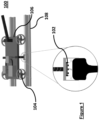
- Figure 1 shows an embodiment of the invention, wherein the system 100 detects the electromagnetic field around a rail, and comprises a non-invasive electromagnetic field sensor 102, and a position sensor 104.
- the sensors may be mounted on a cart 106 that rolls on the running rails 108.
- the cart 106 may be a hand-pulled cart or any vehicle such as a pull cart, a hi-rail vehicle, or a train car.
- the cart may be powered by any means such as human-powered, gas or diesel powered, electric battery powered or electric powered via a traction power system. Leakage currents cause a change in the current on the running rails, for example, a leak may cause the magnitude of the primary current running through the rail to decrease.
- the change in current correlates to a change in the magnetic field in the area around the rail.
- a change in the detected magnetic field around the rail may be indicative of leakage of current from the rail.
- the position sensor 104 which may also be referred to as a chainage sensor or stationing sensor, tracks the position of the magnetic field sensor 102, such as in relation to the conductor (the rail 108).
- the change in magnetic flux around the rail may be correlated to the time and/or cart position data collected, thereby providing a high resolution image to help detect a stray current leak.
- Data analytics may be used to help identify a precise signature that is highly indicative of the location of a current leak
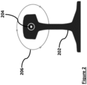
- Figure 2 depicts a cross-section of rail 202 with an electric current 204 traveling forward through the rail (and out of the page in the representative drawing).
- the magnetic field 206 in this case is oriented in a counterclockwise direction around the rail.
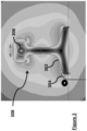
- Figure 3 shows a representative example of the contours and regions of magnetic fields and their intensities around the rail.
- the rail segment 302 is grounded with a ground line 304 as shown in the left bottom portion of the figure.
- the main current 306 passing through the rail is parallel to the direction of the rail.
- the magnetic fields 308 around the rail are linearly correlated with the current running through the rail.
- a baseline measurement of magnetic current around a rail with zero current running through the rail may be determined using a rail instrument, and compared to measurements taken with the same sensor when electric current is running through the rail.
- a known steady current may be injected into the rail causing a known magnetic field around the rail.
- the electric current may be injected into the rail specifically for testing for current leakage and changes / differences in the magnetic field at different points around the rail may be indicative of a leakage current.
- a fluctuating current may be present in the rail, for example as a result of trains running along the rail.
- One or more magnetic sensors may be used to measure the magnetic fields around a powered rail.
- the magnetic sensors may be Hall effect sensors.
- the contactless Hall effect sensor may be moved down the length of a rail taking point measurements of portions of the magnetic field around the rail. Variations in the primary current running through the rail may be determined by measuring and identifying variations in the corresponding magnetic field at one or more locations along the length of the rail. Changes in the magnetic field along the length of the rail, which may be detected by a Hall effect sensor, are linearly correlated with changes in the current running through the rail at the points of measurement. Measurements taken by a conventional Hall effect sensor however are dependent on the distance of that sensor from the rail because the magnetic gradients around a slice of rail can be relatively strong but variable. Such sensors are also negatively affected by natural magnetic grains. As such, even with no current, a significant variation in the detected magnetic field may be acquired by such Hall sensors.
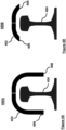
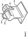
- Figures 4A and 4B shows embodiments of a rail instrument 400A, 400B for detecting electrical or magnetic rail properties of a rail 404.
- the rail instrument 400A,B may be mounted to a cart such as that shown in Figure 1 .
- the rail instrument 400A,400B comprises an open configuration.
- the rail instrument 400A,B comprises an elongated conductor 402 that is configured to aggregate variations in the magnetic field across an area of the rail.
- the elongated conductor 402 may be disposed above the rail 404.
- the elongated conductor 402 may encircle a portion of the radius of the rail 404 to sense the electrical or magnetic properties of multiple faces of the rail.
- the elongated conductor 402 may be in a horseshoe shape.
- the shape of the elongated conducted 402 may be said to be in a "U" or arched configuration. Such a configuration may allow for better movement of the rail instrument along the rail.
- the open portion of a "U” configuration may be positioned about the rail as shown in Figure 4A , such that a portion of the rail 404 is positioned between the open ends of the conductor 406,408.
- the rail instrument may be positioned completely above the rail, such that the open ends of the "U" shaped instrument are higher in space above the top of the rail, similar to as shown in Fig. 4B .
- a "U" shaped metal conductor for the rail instrument may allow for improved measurement of magnetic flux about the rail while also helping avoiding contacting objects in the rail environment with the instrument while it is being passed along the rail. Having the instrument too close to the rail may results in the instrument colliding with something within the rail system environment.
- the rail instrument may be formed of a single piece or multiple pieces.
- the rail instrument may comprise an elongated surface.
- the rail instrument may have two similar shaped pieces that come together to form an elongated surface.
- the elongated surface may be one or more of a planar surface and a "U" shape.
- the pieces may be joined together without any gaps therebetween. Or as shown in Figure 4 , the pieces may be jointed together with a small gap therebetween.
- One or more sensors may be positioned in the middle of the rail instrument, including in the gap between two other pieces.
- the rail instrument may be disposed on a cart that moves along the rail such that the rail instrument detects electric or magnetic rail properties at points along the rail.
- the rail instrument may comprise an elongated surface, such as a planar surface, in one or more of the longitudinal direction and lateral direction in relation to the axis of the rail.
- An elongated surface such as a planar surface of the rail instrument may help detect all of the magnetic flux within the region along a slice of the rail that is covered by the surface of the rail instrument. This may provide measurements that are less sensitive to the natural variation of the magnetic field along a length of the rail, and may also help increase the flux density at the sensor of the rail instrument.
- the elongated surface may further act as a shield to external sources and can make the measurements less sensitive to the gap between the rail and the sensor (including variations in that gap as the instrument is moved along the rail).
- the U-shape may also help further mitigate the natural magnetic variability of the rail in the planar orientation. The elongation of the U-shape down the length of rail may similarly mitigate the natural magnetic variability of the rail in the longitudinal orientation.
- the rail instrument for sensing magnetic field may comprise a magnetic flux concentrator.
- the magnetic flux concentrator may be in an open configuration and comprise a material with a high magnetic permeability combined with a magnetic field sensor, such as a Hall effect magnetic sensor.
- a magnetic flux concentrator may help provide magnetic field readings that are an average of the magnetic field of an area around a portion of the rail at a particular point in time.
- a reading of the average of the magnetic field around an area of a portion of the rail using the flux concentrator may be better for detecting leakage current than merely a reading of the magnetic field at a particular discrete point proximate to the rail using only a conventional Hall effect sensor.
- the magnetic flux concentrator is less sensitive to minor variations in the distance of the sensor from the rail as the sensor is moved along the rail over a period of time.
- the magnetic flux concentrator is also less sensitive to the discrete magnetic field differences between adjacent points on the rail caused by the magnetic profile of the steel rail which is an inherent property of the rail itself.
- the magnetic flux concentrator may be configured to obtain magnetic field readings from a rail which is being supplied with an AC or DC current.
- the magnetic flux concentrator may be configured to see multiple faces of the rail at the same time through the use of an elongated conductor that runs perpendicular to the rail itself.
- the magnetic flux concentrator comprises conductors elongated in a direction that is parallel to the rail.
- the magnetic flux concentrator may comprise an iron core.
- the iron core is a material having a greater magnetic permeability than air.
- the iron core may help one or more of reorient and concentrate the magnetic field across the area around the rail so that the field is focused on a specific point for detection by the magnetic sensor, such as the Hall effect magnetic sensor.
- An iron core may help with using the magnetic flux concentrator to obtain readings of the magnetic fields around the rail when a direct current is being injected to the rail system.
- the magnetic flux concentrator comprising the material with high magnetic permeability and the Hall effect sensor may be in an open configuration, for example an arch, a "U", or a horseshoe shaped configuration.
- Other open configurations of the magnetic flux concentrator may include, without limitation, a generally planar or flat shape, a flattened U shape resembling a C, a shallow arch, a V shape, or any other similar configuration.
- Such open configurations may allow the rail instrument to better envelop a portion of the rail to improve sensing of the magnetic field across a larger area around the rail, but still allowing for the instrument to be moved down the rail quickly (such as on a cart or train) to obtain many readings of a large portion of the rail over a relatively short period of time.
- the open configuration may be such that it materially reduces the risk of the rail instrument unwantedly contacting something while moving the instrument along the rail.
- the Hall effect sensor may be positioned between two pieces of high magnetically permeable material in the flux concentrator.
- the Hall effect sensor may be positioned at the closed end of the "U" shape between two mirror image pieces forming the remainder of the flux concentrator.
- a magnetic sensor other than a Hall effect sensor may be used as part of the magnetic flux concentrator.
- the concentrator may also reduce the effect of the rail's magnetic profile.
- the magnetic flux concentrator may be a narrow magnetic flux concentrator in one or more dimensions.
- the concentrator may extend between about 1mm and 5cm along the length of the rail.
- the narrow concentrator may be used to capture a slice or cross-section of the magnetic flux of the rail at a given position.
- the magnetic flux concentrator 500 may be a deep magnetic flux concentrator 502 extending between about 5cm and 100cm along the length of the rail 504.
- the magnetic flux concentrator 500 comprises a first portion 502A and a second portion 502B, and a magnetic sensor 506 positioned between the first portion 502A and the second portion 502B.
- the deep magnetic flux concentrator 500 may be used to capture an integrated and averaged magnetic flux of an area of the rails that corresponds to the length and width of the concentrator 500 (i.e. over a continuous slices of the magnetic flux in the rail).
- the deep magnetic flux concentrator may provide a larger gain of the signal/current running in the rail, while helping reduce noise and the effects of magnetic inhomogeneities within the rail.
- a leakage current may be detected by simultaneously running two sensors along the rail and measuring the variation in current and/or magnetic field between a first sensor in a first position, and a second sensor in a second position, the second sensor being a select distance behind the first sensor relative to the direction of travel of the sensors.
- the distance may be for example 3 meters, corresponding to a measuring cart or vehicle holding the sensors, up to 100m, up to 200m, or for example as long as the length of a train or longer (through the use of separate carts).
- the position of one sensor may be fixed and the second sensor may be mounted on a cart. Many sensors in series may be used.
- the readings from multiple sensors may be used in various combinations, depending on what data is required for detecting a leak. For example, the readings of sensors passing over the same location of a rail may be used. The readings of sensors, taken at the same time, but for different parts of the same length of rail, may be used.
- two sensors may be used.
- the two sensors may be configured such that the second sensor lags in distance behind the first sensor.
- the two sensors measure at least some portion of the magnetic field around the rail (the magnetic field corresponding to the current passing through the rail).
- the measurements may be of two points of the rail.
- the measurements may be at the same time.
- the measurements may be two points of the rail at the same time.
- the sensors may be better able to detect distributed leaks (such as may be caused by conductive dust).
- the first sensor may be stationary while the second sensor moves along the rail. If there is a distributed leak, the measured magnetic field correlated with the rail current will gradually decrease over time as the mobile sensor moves along the rail (and as compared to the measured magnetic field from the stationary sensor).
- the sensors may be placed on the same or separate vehicles configured to move along the rail. The measurements between the two sensors are compared and leaks are located along the rail when there is a variation between a first sensor's measurement and second sensor's measurement.
- Figure 6 shows two sets of measurements, and their differential, of a sensor (as voltage output from the sensor) as it is continuously moved along a segment of a rail from positions 0 to 1000 mm according to an embodiment of the invention.
- a first set of measurements is taken with no current injected into the system (plot shown in solid black line in Fig. 6 ). This set of measurements identify the fluctuations in the ambient magnetic field created by the steel rail itself.
- a second set of measurements is taken of the same locations of the rail while current is flowing through the rail (for example, an injection of 50A) (plot shown in stippled line in Fig. 6 ).
- the electromagnetic field detection system in this embodiment therefore consists of a magnetic field sensor, and a position sensor input.
- the sensors may be mounted for example on a vehicle (such as a cart) that rolls on the running rails in order to more easily collect a series of measurements along a section of track.
- the instruments do not need to be driven by a vehicle and may instead be used to take point measurements at specific locations in a discontinuous manner.
- Data analytics may help ensure a precise signature for the location of the current leak. Due to the high sensitivity of the sensors used in the system and the significant amount of influence and interference from other sources (other current-carrying conductors, vibration, other sources of current, earth's magnetic field), an advanced data analytics platform may be used to differentiate between the current leakage points on the one hand, from other factors that would produce false-positives on the other hand.
- the combination of a position sensor and/or data analytics with the rail instrument may help provide a precise value of the running rail current before and after a leakage point that uniquely identifies a leakage current point that will require maintenance repair.
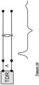
- an open Rogowski-type coil 702 for measuring current along the rail 704 is used.
- the coil 702 comprise a partial toroid of wire 703 such that there is a first end 706 and second end 708, and the ends of the partial toroid do not meet such that a rail 704 may be passed therebetween.
- the open Rogowski coil infers the primary current (i.e. through the rail 704) by integration of the rate of change of the magnetic field and can be used to identify changes in the current.
- the Rogowski coil 702 resolves the AC components of the electrical current as it moves along the rail.
- the magnitude of the current measurement inferred by the coil drops proportionally to the size / magnitude of the leak at the position of the leak (in this test at 600mm).
- Each plot of Figure 8 shows a representative example of a percentage of peak magnitude drops on the same segment of rail for different amounts of current leak.
- two Rogowski coils are used, moving at the same speed at a predetermined distance apart. Differences in the two coil measurements indicate a change in electrical current somewhere between the two coils, thereby locating a leak between the two coils. Specifically, the two coils infer the same proportion of the current and therefore, if a first coil and a second coil detect the same proportion of current, this indicates that there is no leak. If on the other hand, one coil infers less current relative to the other coil, this indicates a leak between the coils.
- the use of two Rogowski coils as a detection method may help to better detect distributed current leaks.
- Figure 9A shows a representation of a rail 902 with a tangential leakage current 904, and Figure 9B shows a magnetic detection coil 906 that is orthogonal to the axis of the rail 902 according to an embodiment of the invention.
- the magnetic coil 902 may be used to directly detect leakage current which travels in a direction other than along the length of the rai I906. This may be tangential to or away from the rail, or orthogonal in another plane, or generally non-parallel and non-orthogonal at an angle askew to a rail.
- the leakage current traveling away from the rail causes the magnetic field around the leakage current to travel in a new direction that is different from the magnetic field corresponding to the primary current traveling through the rail.
- Leakage current 904 may flow vertically, horizontally, or in some combination thereof in any direction, but not via a path that is along the length of the rail.
- an AC current may be injected into the rail while the sensor runs alongside the rail.
- the magnetic sensor ignores the longitudinal current (i.e. the current running through the rail / primary current) and only senses the tangential component of current produced from a leak.
- the location of a leakage current along the rail may be determined by the detected leakage current and the position of the sensor at the point of detection.
- the coil and a series capacitor may form an LC resonant circuit at the AC injection frequency which reduces interference from AC noise in the rail and increases the sensitivity of the coil to the injection frequency.
- leakage currents are detected by sending a pulse through the rail and detecting a reflection or discontinuity of that pulse.
- the reflection or discontinuity signifies the leak at the point of reflection / discontinuity.
- the time domain reflectometry (TDR) method comprises modeling the rail as a transmission line with a characteristic impedance. For example, a system having two parallel conductors where one conductor is the rail and the other is ground, and between the conductors is an insulating material (i.e. dielectric), a characteristic impedance may be established which can transmit a pulse down the length of the transmission line.
- a fast (short) voltage pulse sent into the rail reflects whenever the characteristic impedance changes. A leak will cause a change in impedance.
- the change in impedance for example if there is a short or open circuit, produces a reflection which can be detected by a TDR meter.
- the reflection may be positive or negative depending on which way the impedance changes.
- a leak will generally produce a negative reflection because it is a localized induction to ground.
- the time of flight of the pulse, or the time between a pulse being sent out and the reflection being received can be used to determine the distance from the injection point to the leak.
- the measurement provides a distance from the pulse to the point of reflection. Movement closer to the leak will produce shorter distances until the position of the leak can be determined.
- the distance may be detected up to 100m or up to 200m.
- a current leakage is detected through measurement of the electrical properties of the rail / conductor through inductive measurements which point to a leak. This is achieved by identifying a change in the localized magnetic properties of the rail.
- a loop (of wire for example) created by a conductor can be considered an inductor, and has inductance based on the loop's area.
- a leak in the rail causes a loop comprising: an electrode to the rail, the rail length to the leak, the leak (assumes low resistance to ground), the ground return path, and, a connection to ground. At any point in time, the coil of wire moving along the rail will be between two leakage points.
- Leaks may therefore form parallel loops.
- An LCR meter may be used to measure the inductance along the rail. As the distance between the measurement point and the nearest leak changes, the loop area changes, affecting the measured inductance. The location of the two nearest leaks can be determined by the measured inductance. The measured inductance will go to zero (local minimum) at the location of the leaks.
- any embodiment of the electromagnetic field detection system may be used independently or in combination with any one or more of the other embodiments of the system.
Landscapes
- Physics & Mathematics (AREA)
- Engineering & Computer Science (AREA)
- General Physics & Mathematics (AREA)
- Condensed Matter Physics & Semiconductors (AREA)
- Mechanical Engineering (AREA)
- Health & Medical Sciences (AREA)
- General Health & Medical Sciences (AREA)
- Biomedical Technology (AREA)
- Transportation (AREA)
- Environmental & Geological Engineering (AREA)
- Toxicology (AREA)
- Investigating Or Analyzing Materials By The Use Of Magnetic Means (AREA)
- Measurement Of Length, Angles, Or The Like Using Electric Or Magnetic Means (AREA)
- Testing Of Short-Circuits, Discontinuities, Leakage, Or Incorrect Line Connections (AREA)
- Measurement Of Current Or Voltage (AREA)
Claims (16)
- System zum Lokalisieren eines Stromverlustes in einer Traktionsstromschiene, wobei das System umfasst:ein Fahrzeug, das so konfiguriert ist, dass es sich entlang eines Segments der Schiene bewegt und einen Ort des Fahrzeugs entlang des Segments der Schiene zu verschiedenen Zeitpunkten bereitstellt; undein Schieneninstrument, das auf dem Fahrzeug angeordnet ist, wobei das Schieneninstrument einen Magnetflusskonzentrator in einer offenen Konfiguration umfasst, der einen länglichen Leiter umfasst, der in einer Richtung verläuft, die parallel zu einem Abschnitt der Schiene ist, und einen bogenförmigen oder einen U-förmigen oder einen hufeisenförmigen Querschnitt aufweist, um einen durchschnittlichen Magnetfeldmesswert des Abschnitts der Schiene zu erhalten, wobei das Instrument so konfiguriert ist, dass es Messwerte des durchschnittlichen Magnetfelds über einen Bereich von Abschnitten des Segments der Schiene aufnimmt, während sich das Fahrzeug entlang des Segments bewegt,einen Prozessor zum Empfangen der Orte des Fahrzeugs und der Messwerte vom Schieneninstrument über einen Zeitraum und zum Bestimmen des Ortes eines Stromverlustes in der Schiene basierend auf den Orten des Fahrzeugs und den Schieneninstrument-Messwerten.
- System nach Anspruch 1, wobei das Schieneninstrument eine offene Rogowski-Spule umfasst.
- System nach Anspruch 2, wobei die Rogowski-Spule so abgestimmt ist, dass sie bei einer bestimmten Frequenz in Resonanz schwingt, oder die Rogowski-Spule so gefiltert ist, dass sie eine bestimmte Frequenz isoliert.
- System nach Anspruch 1, wobei das Material des Magnetflusskonzentrators zwei Abschnitte umfasst, wobei der Magnetsensor zwischen den beiden Abschnitten des Materials angeordnet ist.
- System nach Anspruch 1, wobei der Magnetflusskonzentrator ein schmaler Magnetflusskonzentrator oder ein tiefer Magnetflusskonzentrator ist, wobei sich der Flusskonzentrator über eine ausgewählte Distanz in einer Richtung parallel zu einer Länge der Traktionsstromschiene erstreckt.
- System nach Anspruch 1, wobei der Magnetsensor ein Hall-Effekt-Sensor, ein Magnettransistor, ein AMR-Magnetometer, ein GMR-Magnetometer, ein Magnetometer mit magnetischem Tunnelkontakt, ein auf der Lorentzkraft basierender MEMS-Sensor, ein auf einem Elektronentunnel basierender MEMS-Sensor, ein Fluxgate-Magnetometer, ein Spulenmagnetfeldsensor oder ein SQUID-Magnetometer ist.
- System nach Anspruch 1, wobei das Instrument einen länglichen Leiter umfasst, der tangential oder senkrecht zu einem Abschnitt der Schiene verläuft, um eine durchschnittliche Magnetfeldmessung des Abschnitts der Schiene zu erhalten.
- System nach Anspruch 1, wobei der Leiter zwei Enden umfasst und mindestens ein Abschnitt der Schiene zwischen den beiden Enden angeordnet ist.
- Verfahren zum Bestimmen eines Stromverlustes entlang einer Traktionsstromschiene, wobei das Verfahren umfasst:Laufen lassen eines Sensors mit einem Magnetflusskonzentrator entlang der Schiene, wobei der Magnetflusskonzentrator in einer offenen Konfiguration ist und einen länglichen Leiter umfasst, der in einer Richtung parallel zu einem Abschnitt der Schiene verläuft und einen bogenförmigen oder einen U-förmigen oder einen hufeisenförmigen Querschnitt aufweist, um einen durchschnittlichen Magnetfeldmesswert des Abschnitts der Schiene zu erhalten;Einspeisen eines Stroms in die Schiene, um ein bekanntes Magnetfeld um die Schiene herum zu erzeugen;Erfassen einer Differenz zwischen dem durchschnittlichen Magnetfeldmesswert und dem bekannten Magnetfeld;Bestimmen einer Position des Sensors entlang der Schiene, an der die Differenz erfasst wird; undBestimmen des Stromverlustes an dem Ort entlang der Schiene basierend auf der Differenz und der Position.
- Verfahren nach Anspruch 9, wobei der Sensor eine magnetische Erfassungsspule ist, die orthogonal zur Schiene angeordnet ist.
- Schieneninstrument zum Erfassen elektrischer oder magnetischer Schieneneigenschaften an Punkten entlang einer Traktionsstromschiene, wobei das Schieneninstrument einen Magnetflusskonzentrator in einer offenen Konfiguration umfasst, der einen länglichen Leiter umfasst, der in einer Richtung parallel zu einem Abschnitt der Schiene verläuft und einen bogenförmigen oder einen U-förmigen oder einen hufeisenförmigen Querschnitt aufweist, um einen durchschnittlichen Magnetfeldmesswert des Abschnitts der Schiene zu erhalten.
- Schieneninstrument nach Anspruch 11, wobei der Magnetflusskonzentrator ein Material mit hoher magnetischer Permeabilität und einen Magnetsensor umfasst.
- Schieneninstrument nach Anspruch 11, wobei der Magnetsensor zwischen zwei Abschnitten des Materials angeordnet ist.
- Schieneninstrument nach Anspruch 11, umfassend eine offene Rogowski-Spule.
- Schieneninstrument nach Anspruch 12, wobei der Magnetsensor ein Hall-Effekt-Sensor, ein Magnettransistor, ein AMR-Magnetometer, ein GMR-Magnetometer, ein Magnetometer mit magnetischem Tunnelkontakt, ein auf der Lorentzkraft basierender MEMS-Sensor, ein auf einem Elektronentunnel basierender MEMS-Sensor, ein Fluxgate-Magnetometer, ein Spulenmagnetfeldsensor oder ein SQUID-Magnetometer ist.
- Verwendung des Schieneninstruments nach Anspruch 11 zur Erfassung eines Verluststroms in der Traktionsstromschiene.
Applications Claiming Priority (2)
| Application Number | Priority Date | Filing Date | Title |
|---|---|---|---|
| US202063007595P | 2020-04-09 | 2020-04-09 | |
| PCT/CA2021/050476 WO2021203204A1 (en) | 2020-04-09 | 2021-04-09 | Device, system and method for detecting leakage current for traction power system |
Publications (4)
| Publication Number | Publication Date |
|---|---|
| EP4132835A1 EP4132835A1 (de) | 2023-02-15 |
| EP4132835A4 EP4132835A4 (de) | 2023-11-22 |
| EP4132835C0 EP4132835C0 (de) | 2025-03-05 |
| EP4132835B1 true EP4132835B1 (de) | 2025-03-05 |
Family
ID=78022380
Family Applications (1)
| Application Number | Title | Priority Date | Filing Date |
|---|---|---|---|
| EP21784599.9A Active EP4132835B1 (de) | 2020-04-09 | 2021-04-09 | Vorrichtung, system und verfahren zur erkennung von leckstrom für ein traktionsstromsystem |
Country Status (7)
| Country | Link |
|---|---|
| US (1) | US12145636B2 (de) |
| EP (1) | EP4132835B1 (de) |
| AU (1) | AU2021252448B2 (de) |
| CA (1) | CA3174633A1 (de) |
| ES (1) | ES3023032T3 (de) |
| PL (1) | PL4132835T3 (de) |
| WO (1) | WO2021203204A1 (de) |
Families Citing this family (4)
| Publication number | Priority date | Publication date | Assignee | Title |
|---|---|---|---|---|
| CN112327209B (zh) * | 2020-11-03 | 2022-09-13 | 中车青岛四方机车车辆股份有限公司 | 轨道车辆牵引系统漏电流检测方法、装置及轨道车辆 |
| CN115951221B (zh) * | 2022-01-04 | 2023-07-25 | 国仪量子(合肥)技术有限公司 | 电池包漏放电性能的检测方法和检测设备 |
| CN116047363B (zh) * | 2023-04-03 | 2023-08-18 | 华东交通大学 | 一种轨道列车杂散电流的监测方法及监测系统 |
| CN116552598B (zh) * | 2023-07-10 | 2023-11-07 | 西南交通大学 | 一种永磁轨道不平顺检测装置及方法 |
Family Cites Families (11)
| Publication number | Priority date | Publication date | Assignee | Title |
|---|---|---|---|---|
| US2958818A (en) * | 1957-05-01 | 1960-11-01 | Sperry Prod Inc | Rail flaw detector mechanism |
| WO1995030878A1 (de) * | 1994-05-06 | 1995-11-16 | Erich Permann | Eisenbahnschienenkonturmessverfahren |
| US5586736A (en) * | 1995-06-16 | 1996-12-24 | Harmon Industries, Inc. | Cab signal sensor with noise suppression |
| WO2002030729A1 (en) * | 2000-10-10 | 2002-04-18 | Sperry Rail, Inc. | Hi-rail vehicle-based rail inspection system |
| US7481400B2 (en) | 2005-07-01 | 2009-01-27 | Portec, Rail Products Ltd. | Railway wheel sensor |
| US7791353B2 (en) * | 2007-02-13 | 2010-09-07 | California Institute Of Technology | Ground loop locator |
| US8766810B2 (en) * | 2012-07-08 | 2014-07-01 | International Intelligent Metering, LLC | Indirect measurement method and system for monitoring and reporting leakage currents |
| CA2971075C (en) * | 2014-12-24 | 2024-03-26 | Technological Resources Pty Ltd | A system for detecting a break in a rail |
| NL2015770B1 (en) * | 2015-11-11 | 2017-05-29 | Conductis B V | Monitoring of electric railway systems. |
| CN111766292A (zh) * | 2019-04-02 | 2020-10-13 | 四川大学 | 一种基于零提离滚动磁化的钢轨漏磁检测装置 |
| ES2974765T3 (es) * | 2019-11-19 | 2024-07-01 | Alstom Holdings | Sistema, método y vehículo ferroviario para monitorizar un sistema de tercer carril de una línea ferroviaria |
-
2021
- 2021-04-09 AU AU2021252448A patent/AU2021252448B2/en active Active
- 2021-04-09 WO PCT/CA2021/050476 patent/WO2021203204A1/en not_active Ceased
- 2021-04-09 US US17/917,480 patent/US12145636B2/en active Active
- 2021-04-09 PL PL21784599.9T patent/PL4132835T3/pl unknown
- 2021-04-09 CA CA3174633A patent/CA3174633A1/en active Pending
- 2021-04-09 ES ES21784599T patent/ES3023032T3/es active Active
- 2021-04-09 EP EP21784599.9A patent/EP4132835B1/de active Active
Also Published As
| Publication number | Publication date |
|---|---|
| ES3023032T3 (en) | 2025-05-29 |
| PL4132835T3 (pl) | 2025-06-09 |
| EP4132835C0 (de) | 2025-03-05 |
| AU2021252448A1 (en) | 2022-12-08 |
| CA3174633A1 (en) | 2021-10-14 |
| US12145636B2 (en) | 2024-11-19 |
| AU2021252448B2 (en) | 2025-05-29 |
| US20230084963A1 (en) | 2023-03-16 |
| EP4132835A4 (de) | 2023-11-22 |
| WO2021203204A1 (en) | 2021-10-14 |
| EP4132835A1 (de) | 2023-02-15 |
Similar Documents
| Publication | Publication Date | Title |
|---|---|---|
| EP4132835B1 (de) | Vorrichtung, system und verfahren zur erkennung von leckstrom für ein traktionsstromsystem | |
| EP3237265B1 (de) | System zur detektion eines bruchs in einer schiene | |
| US6995556B2 (en) | Electromagnetic gage sensing system and method for railroad track inspection | |
| JP4112610B2 (ja) | レール搭載車両の速度測定装置 | |
| NL2015770B1 (en) | Monitoring of electric railway systems. | |
| Ayambire et al. | Real-time and contactless initial current traveling wave measurement for overhead transmission line fault detection based on tunnel magnetoresistive sensors | |
| CN107750376B (zh) | 车辆检测设备 | |
| JP2526578B2 (ja) | 塗膜損傷検知方法 | |
| JP5192706B2 (ja) | 地絡事故点探査装置及びそれを用いた地絡事故点探査方法 | |
| Mirzaei et al. | A linear eddy current speed sensor with a perpendicular coils configuration | |
| KR100684465B1 (ko) | 철도 차량의 속도 측정 방법 및 그 장치 | |
| CN100461229C (zh) | 地感线圈式测速仪的检测方法 | |
| JP5687161B2 (ja) | 地上コイルの絶縁診断方法及びその装置 | |
| BR102016018415B1 (pt) | Sistema de avaliação de rota | |
| US12459551B2 (en) | Broken rail detector | |
| KR101192456B1 (ko) | 전자기 유도를 이용한 철도 레일의 횡변위 측정 시스템, 방법 및 센서 | |
| CN114791530B (zh) | 地铁与油气管道之间耦合关系的检测方法 | |
| JP4367601B2 (ja) | 電流計測システム、計測装置及び計測方法 | |
| JP6896250B2 (ja) | オープン形コイルの渦電流形センサ及びこれを用いたレール変位測定方法 | |
| JP2911383B2 (ja) | トロリ線摩耗限検知装置 | |
| JP4029118B2 (ja) | 埋設金属管のメタルタッチ部検出方法 | |
| EP4471446A1 (de) | Sensoranordnung | |
| JP2017187384A (ja) | 渦電流形センサを用いたレール摩耗測定方法及びその測定装置 | |
| CN119985684A (zh) | 一种基于远场涡流的螺栓连接结构孔边损伤监测方法 | |
| RU2576979C1 (ru) | Способ обнаружения обрывов протяженных анодных заземлителей |
Legal Events
| Date | Code | Title | Description |
|---|---|---|---|
| STAA | Information on the status of an ep patent application or granted ep patent |
Free format text: STATUS: THE INTERNATIONAL PUBLICATION HAS BEEN MADE |
|
| PUAI | Public reference made under article 153(3) epc to a published international application that has entered the european phase |
Free format text: ORIGINAL CODE: 0009012 |
|
| STAA | Information on the status of an ep patent application or granted ep patent |
Free format text: STATUS: REQUEST FOR EXAMINATION WAS MADE |
|
| 17P | Request for examination filed |
Effective date: 20221108 |
|
| AK | Designated contracting states |
Kind code of ref document: A1 Designated state(s): AL AT BE BG CH CY CZ DE DK EE ES FI FR GB GR HR HU IE IS IT LI LT LU LV MC MK MT NL NO PL PT RO RS SE SI SK SM TR |
|
| P01 | Opt-out of the competence of the unified patent court (upc) registered |
Effective date: 20230526 |
|
| DAV | Request for validation of the european patent (deleted) | ||
| DAX | Request for extension of the european patent (deleted) | ||
| A4 | Supplementary search report drawn up and despatched |
Effective date: 20231020 |
|
| RIC1 | Information provided on ipc code assigned before grant |
Ipc: G01R 33/07 20060101ALI20231016BHEP Ipc: G01R 15/18 20060101ALI20231016BHEP Ipc: B61L 25/02 20060101ALI20231016BHEP Ipc: B60M 3/00 20060101ALI20231016BHEP Ipc: B61K 9/08 20060101AFI20231016BHEP |
|
| GRAP | Despatch of communication of intention to grant a patent |
Free format text: ORIGINAL CODE: EPIDOSNIGR1 |
|
| STAA | Information on the status of an ep patent application or granted ep patent |
Free format text: STATUS: GRANT OF PATENT IS INTENDED |
|
| INTG | Intention to grant announced |
Effective date: 20241004 |
|
| GRAS | Grant fee paid |
Free format text: ORIGINAL CODE: EPIDOSNIGR3 |
|
| GRAA | (expected) grant |
Free format text: ORIGINAL CODE: 0009210 |
|
| STAA | Information on the status of an ep patent application or granted ep patent |
Free format text: STATUS: THE PATENT HAS BEEN GRANTED |
|
| AK | Designated contracting states |
Kind code of ref document: B1 Designated state(s): AL AT BE BG CH CY CZ DE DK EE ES FI FR GB GR HR HU IE IS IT LI LT LU LV MC MK MT NL NO PL PT RO RS SE SI SK SM TR |
|
| REG | Reference to a national code |
Ref country code: GB Ref legal event code: FG4D |
|
| REG | Reference to a national code |
Ref country code: CH Ref legal event code: EP |
|
| REG | Reference to a national code |
Ref country code: IE Ref legal event code: FG4D |
|
| REG | Reference to a national code |
Ref country code: DE Ref legal event code: R096 Ref document number: 602021027234 Country of ref document: DE |
|
| U01 | Request for unitary effect filed |
Effective date: 20250401 |
|
| U07 | Unitary effect registered |
Designated state(s): AT BE BG DE DK EE FI FR IT LT LU LV MT NL PT RO SE SI Effective date: 20250407 |
|
| P04 | Withdrawal of opt-out of the competence of the unified patent court (upc) registered |
Free format text: CASE NUMBER: APP_16199/2025 Effective date: 20250402 |
|
| REG | Reference to a national code |
Ref country code: ES Ref legal event code: FG2A Ref document number: 3023032 Country of ref document: ES Kind code of ref document: T3 Effective date: 20250529 |
|
| U20 | Renewal fee for the european patent with unitary effect paid |
Year of fee payment: 5 Effective date: 20250428 |
|
| PG25 | Lapsed in a contracting state [announced via postgrant information from national office to epo] |
Ref country code: RS Free format text: LAPSE BECAUSE OF FAILURE TO SUBMIT A TRANSLATION OF THE DESCRIPTION OR TO PAY THE FEE WITHIN THE PRESCRIBED TIME-LIMIT Effective date: 20250605 |
|
| PGFP | Annual fee paid to national office [announced via postgrant information from national office to epo] |
Ref country code: PL Payment date: 20250403 Year of fee payment: 5 |
|
| PGFP | Annual fee paid to national office [announced via postgrant information from national office to epo] |
Ref country code: ES Payment date: 20250505 Year of fee payment: 5 |
|
| PG25 | Lapsed in a contracting state [announced via postgrant information from national office to epo] |
Ref country code: NO Free format text: LAPSE BECAUSE OF FAILURE TO SUBMIT A TRANSLATION OF THE DESCRIPTION OR TO PAY THE FEE WITHIN THE PRESCRIBED TIME-LIMIT Effective date: 20250605 |
|
| PG25 | Lapsed in a contracting state [announced via postgrant information from national office to epo] |
Ref country code: HR Free format text: LAPSE BECAUSE OF FAILURE TO SUBMIT A TRANSLATION OF THE DESCRIPTION OR TO PAY THE FEE WITHIN THE PRESCRIBED TIME-LIMIT Effective date: 20250305 |
|
| PG25 | Lapsed in a contracting state [announced via postgrant information from national office to epo] |
Ref country code: GR Free format text: LAPSE BECAUSE OF FAILURE TO SUBMIT A TRANSLATION OF THE DESCRIPTION OR TO PAY THE FEE WITHIN THE PRESCRIBED TIME-LIMIT Effective date: 20250606 |
|
| PGFP | Annual fee paid to national office [announced via postgrant information from national office to epo] |
Ref country code: CZ Payment date: 20250401 Year of fee payment: 5 |
|
| PG25 | Lapsed in a contracting state [announced via postgrant information from national office to epo] |
Ref country code: SM Free format text: LAPSE BECAUSE OF FAILURE TO SUBMIT A TRANSLATION OF THE DESCRIPTION OR TO PAY THE FEE WITHIN THE PRESCRIBED TIME-LIMIT Effective date: 20250305 |
|
| PG25 | Lapsed in a contracting state [announced via postgrant information from national office to epo] |
Ref country code: SK Free format text: LAPSE BECAUSE OF FAILURE TO SUBMIT A TRANSLATION OF THE DESCRIPTION OR TO PAY THE FEE WITHIN THE PRESCRIBED TIME-LIMIT Effective date: 20250305 |
|
| PG25 | Lapsed in a contracting state [announced via postgrant information from national office to epo] |
Ref country code: IS Free format text: LAPSE BECAUSE OF FAILURE TO SUBMIT A TRANSLATION OF THE DESCRIPTION OR TO PAY THE FEE WITHIN THE PRESCRIBED TIME-LIMIT Effective date: 20250705 |
|
| REG | Reference to a national code |
Ref country code: CH Ref legal event code: H13 Free format text: ST27 STATUS EVENT CODE: U-0-0-H10-H13 (AS PROVIDED BY THE NATIONAL OFFICE) Effective date: 20251125 |