EP4131999A1 - Mehrkanaliges audiosystem, mehrkanalige audiovorrichtung, programm und mehrkanaliges audiowiedergabeverfahren - Google Patents
Mehrkanaliges audiosystem, mehrkanalige audiovorrichtung, programm und mehrkanaliges audiowiedergabeverfahren Download PDFInfo
- Publication number
- EP4131999A1 EP4131999A1 EP20927835.7A EP20927835A EP4131999A1 EP 4131999 A1 EP4131999 A1 EP 4131999A1 EP 20927835 A EP20927835 A EP 20927835A EP 4131999 A1 EP4131999 A1 EP 4131999A1
- Authority
- EP
- European Patent Office
- Prior art keywords
- channel
- reproduction
- signal
- audio device
- reproduction data
- Prior art date
- Legal status (The legal status is an assumption and is not a legal conclusion. Google has not performed a legal analysis and makes no representation as to the accuracy of the status listed.)
- Granted
Links
Images




Classifications
-
- H—ELECTRICITY
- H04—ELECTRIC COMMUNICATION TECHNIQUE
- H04S—STEREOPHONIC SYSTEMS
- H04S7/00—Indicating arrangements; Control arrangements, e.g. balance control
- H04S7/30—Control circuits for electronic adaptation of the sound field
- H04S7/301—Automatic calibration of stereophonic sound system, e.g. with test microphone
-
- H—ELECTRICITY
- H04—ELECTRIC COMMUNICATION TECHNIQUE
- H04R—LOUDSPEAKERS, MICROPHONES, GRAMOPHONE PICK-UPS OR LIKE ACOUSTIC ELECTROMECHANICAL TRANSDUCERS; ELECTRIC HEARING AIDS; PUBLIC ADDRESS SYSTEMS
- H04R3/00—Circuits for transducers
- H04R3/12—Circuits for transducers for distributing signals to two or more loudspeakers
-
- G—PHYSICS
- G10—MUSICAL INSTRUMENTS; ACOUSTICS
- G10K—SOUND-PRODUCING DEVICES; METHODS OR DEVICES FOR PROTECTING AGAINST, OR FOR DAMPING, NOISE OR OTHER ACOUSTIC WAVES IN GENERAL; ACOUSTICS NOT OTHERWISE PROVIDED FOR
- G10K11/00—Methods or devices for transmitting, conducting or directing sound in general; Methods or devices for protecting against, or for damping, noise or other acoustic waves in general
- G10K11/16—Methods or devices for protecting against, or for damping, noise or other acoustic waves in general
- G10K11/175—Methods or devices for protecting against, or for damping, noise or other acoustic waves in general using interference effects; Masking sound
- G10K11/178—Methods or devices for protecting against, or for damping, noise or other acoustic waves in general using interference effects; Masking sound by electro-acoustically regenerating the original acoustic waves in anti-phase
-
- G—PHYSICS
- G10—MUSICAL INSTRUMENTS; ACOUSTICS
- G10K—SOUND-PRODUCING DEVICES; METHODS OR DEVICES FOR PROTECTING AGAINST, OR FOR DAMPING, NOISE OR OTHER ACOUSTIC WAVES IN GENERAL; ACOUSTICS NOT OTHERWISE PROVIDED FOR
- G10K11/00—Methods or devices for transmitting, conducting or directing sound in general; Methods or devices for protecting against, or for damping, noise or other acoustic waves in general
- G10K11/16—Methods or devices for protecting against, or for damping, noise or other acoustic waves in general
- G10K11/175—Methods or devices for protecting against, or for damping, noise or other acoustic waves in general using interference effects; Masking sound
- G10K11/178—Methods or devices for protecting against, or for damping, noise or other acoustic waves in general using interference effects; Masking sound by electro-acoustically regenerating the original acoustic waves in anti-phase
- G10K11/1781—Methods or devices for protecting against, or for damping, noise or other acoustic waves in general using interference effects; Masking sound by electro-acoustically regenerating the original acoustic waves in anti-phase characterised by the analysis of input or output signals, e.g. frequency range, modes, transfer functions
- G10K11/17813—Methods or devices for protecting against, or for damping, noise or other acoustic waves in general using interference effects; Masking sound by electro-acoustically regenerating the original acoustic waves in anti-phase characterised by the analysis of input or output signals, e.g. frequency range, modes, transfer functions characterised by the analysis of the acoustic paths, e.g. estimating, calibrating or testing of transfer functions or cross-terms
- G10K11/17817—Methods or devices for protecting against, or for damping, noise or other acoustic waves in general using interference effects; Masking sound by electro-acoustically regenerating the original acoustic waves in anti-phase characterised by the analysis of input or output signals, e.g. frequency range, modes, transfer functions characterised by the analysis of the acoustic paths, e.g. estimating, calibrating or testing of transfer functions or cross-terms between the output signals and the error signals, i.e. secondary path
-
- G—PHYSICS
- G10—MUSICAL INSTRUMENTS; ACOUSTICS
- G10K—SOUND-PRODUCING DEVICES; METHODS OR DEVICES FOR PROTECTING AGAINST, OR FOR DAMPING, NOISE OR OTHER ACOUSTIC WAVES IN GENERAL; ACOUSTICS NOT OTHERWISE PROVIDED FOR
- G10K11/00—Methods or devices for transmitting, conducting or directing sound in general; Methods or devices for protecting against, or for damping, noise or other acoustic waves in general
- G10K11/16—Methods or devices for protecting against, or for damping, noise or other acoustic waves in general
- G10K11/175—Methods or devices for protecting against, or for damping, noise or other acoustic waves in general using interference effects; Masking sound
- G10K11/178—Methods or devices for protecting against, or for damping, noise or other acoustic waves in general using interference effects; Masking sound by electro-acoustically regenerating the original acoustic waves in anti-phase
- G10K11/1783—Methods or devices for protecting against, or for damping, noise or other acoustic waves in general using interference effects; Masking sound by electro-acoustically regenerating the original acoustic waves in anti-phase handling or detecting of non-standard events or conditions, e.g. changing operating modes under specific operating conditions
- G10K11/17833—Methods or devices for protecting against, or for damping, noise or other acoustic waves in general using interference effects; Masking sound by electro-acoustically regenerating the original acoustic waves in anti-phase handling or detecting of non-standard events or conditions, e.g. changing operating modes under specific operating conditions by using a self-diagnostic function or a malfunction prevention function, e.g. detecting abnormal output levels
-
- G—PHYSICS
- G10—MUSICAL INSTRUMENTS; ACOUSTICS
- G10K—SOUND-PRODUCING DEVICES; METHODS OR DEVICES FOR PROTECTING AGAINST, OR FOR DAMPING, NOISE OR OTHER ACOUSTIC WAVES IN GENERAL; ACOUSTICS NOT OTHERWISE PROVIDED FOR
- G10K11/00—Methods or devices for transmitting, conducting or directing sound in general; Methods or devices for protecting against, or for damping, noise or other acoustic waves in general
- G10K11/16—Methods or devices for protecting against, or for damping, noise or other acoustic waves in general
- G10K11/175—Methods or devices for protecting against, or for damping, noise or other acoustic waves in general using interference effects; Masking sound
- G10K11/178—Methods or devices for protecting against, or for damping, noise or other acoustic waves in general using interference effects; Masking sound by electro-acoustically regenerating the original acoustic waves in anti-phase
- G10K11/1787—General system configurations
- G10K11/17875—General system configurations using an error signal without a reference signal, e.g. pure feedback
-
- H—ELECTRICITY
- H04—ELECTRIC COMMUNICATION TECHNIQUE
- H04R—LOUDSPEAKERS, MICROPHONES, GRAMOPHONE PICK-UPS OR LIKE ACOUSTIC ELECTROMECHANICAL TRANSDUCERS; ELECTRIC HEARING AIDS; PUBLIC ADDRESS SYSTEMS
- H04R29/00—Monitoring arrangements; Testing arrangements
- H04R29/001—Monitoring arrangements; Testing arrangements for loudspeakers
- H04R29/002—Loudspeaker arrays
-
- H—ELECTRICITY
- H04—ELECTRIC COMMUNICATION TECHNIQUE
- H04R—LOUDSPEAKERS, MICROPHONES, GRAMOPHONE PICK-UPS OR LIKE ACOUSTIC ELECTROMECHANICAL TRANSDUCERS; ELECTRIC HEARING AIDS; PUBLIC ADDRESS SYSTEMS
- H04R5/00—Stereophonic arrangements
- H04R5/04—Circuit arrangements, e.g. for selective connection of amplifier inputs/outputs to loudspeakers, for loudspeaker detection, or for adaptation of settings to personal preferences or hearing impairments
-
- G—PHYSICS
- G10—MUSICAL INSTRUMENTS; ACOUSTICS
- G10K—SOUND-PRODUCING DEVICES; METHODS OR DEVICES FOR PROTECTING AGAINST, OR FOR DAMPING, NOISE OR OTHER ACOUSTIC WAVES IN GENERAL; ACOUSTICS NOT OTHERWISE PROVIDED FOR
- G10K2210/00—Details of active noise control [ANC] covered by G10K11/178 but not provided for in any of its subgroups
- G10K2210/10—Applications
- G10K2210/105—Appliances, e.g. washing machines or dishwashers
- G10K2210/1053—Hi-fi, i.e. anything involving music, radios or loudspeakers
-
- G—PHYSICS
- G10—MUSICAL INSTRUMENTS; ACOUSTICS
- G10K—SOUND-PRODUCING DEVICES; METHODS OR DEVICES FOR PROTECTING AGAINST, OR FOR DAMPING, NOISE OR OTHER ACOUSTIC WAVES IN GENERAL; ACOUSTICS NOT OTHERWISE PROVIDED FOR
- G10K2210/00—Details of active noise control [ANC] covered by G10K11/178 but not provided for in any of its subgroups
- G10K2210/50—Miscellaneous
- G10K2210/504—Calibration
-
- H—ELECTRICITY
- H04—ELECTRIC COMMUNICATION TECHNIQUE
- H04R—LOUDSPEAKERS, MICROPHONES, GRAMOPHONE PICK-UPS OR LIKE ACOUSTIC ELECTROMECHANICAL TRANSDUCERS; ELECTRIC HEARING AIDS; PUBLIC ADDRESS SYSTEMS
- H04R2420/00—Details of connection covered by H04R, not provided for in its groups
- H04R2420/07—Applications of wireless loudspeakers or wireless microphones
Definitions
- the present invention relates to a technology for reproducing multi-channel audio.
- a multi-channel audio device that reproduces a multi-channel audio signal through use of a plurality of speakers.
- a multi-channel audio device as described in Patent Literature 1 amplifies an audio reproduction signal for each channel of a multi-channel audio signal, and outputs the audio reproduction signal from a speaker corresponding to this channel.
- some multi-channel audio devices enable acoustic profile information (including an output timing and a volume level) on an audio reproduction signal to be set for each channel of the multi-channel audio signal.
- a multi-channel audio device as described in Patent Literature 2 collects, for each channel of a multi-channel audio signal, sound of a test signal output from a speaker corresponding to this channel by a dedicated measurement microphone installed at a listening point, and measures a delay time and an attenuation rate of the sound. Then, the acoustic profile information is set for each channel of the multi-channel audio signal so that acoustic characteristics of the audio reproduction signal output from the speaker corresponding to this channel are optimum at the listening point.
- the multi-channel audio device of the related art as described in Patent Literature 2 which can set acoustic profile information for each channel requires a dedicated measurement microphone to be attached, and is accordingly increased in cost.
- the dedicated measurement microphone also requires to be connected to the multi-channel audio device by a cord, which is a hassle.
- a wireless terminal provided with a microphone such as a smartphone, a tablet PC, or a smart speaker, is placed at a listening point of a multi-channel audio device.
- the multi-channel audio device reproduces, from a multi-channel audio signal, audio reproduction signals of a plurality of channels, and outputs the audio reproduction signals of the respective channels for each channel separately from the channels' corresponding speakers.
- the wireless terminal collects ambient sounds at the listening point, and feeds collected sound signals of the collected sounds back to the multi-channel audio device.
- the multi-channel audio device identifies, as noise components, differences between the collected sound signals fed back from the wireless terminal and the audio reproduction signals of the plurality of channels output from the plurality of speakers, and generates noise canceling signals opposite in phase from the identified noise components.
- the multi-channel audio device outputs the noise canceling signals from one of the plurality of speakers.
- the multi-channel audio device transmits the noise canceling signals to the wireless terminal to output the noise canceling signals from the wireless terminal.
- a multi-channel audio system including: a multi-channel audio device configured to reproduce and output a multi-channel audio signal with use of a plurality of speakers; and a wireless terminal placed at a listening point of the multi-channel audio device, the wireless terminal including: sound collection means for collecting ambient sounds at the listening point; and collected sound signal transmitting means for transmitting, to the multi-channel audio device, collected sound signals of the ambient sounds collected by the sound collection means, the multi-channel audio device including: audio reproduction means for reproducing, from the multi-channel audio signal, audio reproduction signals of a plurality of channels; audio output means for outputting, for each of the plurality of channels separately, the audio reproduction signals of the plurality of channels reproduced by the audio reproduction means, in a manner that outputs the audio reproduction signal of one channel from one of the plurality of speakers that corresponds to the one channel; collected sound signal receiving means for receiving the collected sound signals from the wireless terminal; noise component identifying means for identifying, as noise components, differences between the collected
- the wireless terminal placed at the listening point is provided with a recording and reproducing function.
- the wireless terminal includes a source sound of a test signal.
- the wireless terminal receives test signal reproducing operation from a user, the wireless terminal transmits a test signal reproducing instruction including a designated channel to the multi-channel audio device, records, as channel reproduction data, the test signal output from the multi-channel audio device through one of the plurality of speakers that corresponds to the designated channel, and reproduces the source sound of the test signal to record this reproduced source sound as source sound reproduction data, without externally outputting the reproduced source sound from a speaker thereof.
- the wireless terminal then transmits the channel reproduction data of the designated channel and the source sound reproduction data to the multi-channel audio device.
- the multi-channel audio device compares the channel reproduction data and the source sound reproduction data to each other to measure a delay time and an attenuation rate of the channel reproduction data with respect to the source sound reproduction data.
- the multi-channel audio device generates, based on results of the measurement, acoustic profile information including an output timing and a volume level of the designated channel, and sets this acoustic profile information as conditions under which an audio reproduction signal of the designated channel is output.
- the wireless terminal further includes: test signal reproduction instruction means for transmitting, to the multi-channel audio device, a test signal reproducing instruction including a designated channel, by following test signal reproducing operation received from a user; channel reproduction data recording means for recording, as channel reproduction data of the designated channel, a test signal that is output, in response to the test signal reproducing instruction transmitted by the test signal reproduction instruction means, from the multi-channel audio device via a corresponding speaker and collected by the sound collection means, the corresponding speaker being one of the plurality of speakers that corresponds to the designated channel; source sound reproduction data recording means for reproducing, in synchronization with start of the recording by the channel reproduction data recording means, a source sound of the test signal that is stored in advance, and recording reproduction data of the source sound as source sound reproduction data, without externally outputting the reproduction data of the source sound; and measurement data transmitting means for transmitting, to the multi-channel audio device, measurement data of the designated
- the audio reproduction signals of the respective channels output by the multi-channel audio device for each channel separately from the channels' corresponding speakers are collected through sound collection by the wireless terminal placed at the listening point of the multi-channel audio device, and collected sound signals thereof are fed back to the multi-channel audio device.
- the multi-channel audio device identifies, as noise components, differences between the collected sound signals fed back from the wireless terminal and the audio reproduction signals of the plurality of channels output from the plurality of speakers, and outputs noise canceling signals opposite in phase from the noise components, from one of the plurality of speakers or from the wireless terminal. Accordingly, even in an environment having noise, comfortable enjoyment of multi-channel audio is accomplished by canceling the noise.
- a wireless terminal provided with a recording and reproducing function such as a smartphone, a tablet PC, or a smart speaker
- a measurement microphone for generating acoustic profile information
- a dedicated measurement microphone is not required to be attached to the multi-channel audio device.
- a user places the wireless terminal at the listening point of the multi-channel audio device, and the user is not required to connect the wireless terminal and the multi-channel audio device to each other by a cord. Acoustic profile information of each channel can accordingly be generated by simple operation without increasing cost.
- FIG. 1 is a schematic configuration diagram of a multi-channel audio system according to this embodiment.
- the multi-channel audio system includes a multi-channel audio device 1 connected to a media server 4 via an access point 6 and a network 5, such as a WAN or a LAN, and a wireless terminal 3 wirelessly connected to the multi-channel audio device 1 via the access point 6.
- a network 5 such as a WAN or a LAN
- the multi-channel audio device 1 downloads a multi-channel audio signal from the media server 4, reproduces, from the downloaded multi-channel audio signal, audio reproduction signals of a plurality of channels, and outputs the audio reproduction signals from a plurality of speakers 2-1 to 2-6 (hereinafter may simply be referred to as "speakers 2").
- a case of reproducing and outputting a multi-channel audio signal of 5.1 channels is illustrated as an example, and the six speakers 2-1 to 2-6 corresponding to a front right (FR) channel, a front left (FL) channel, a center (C) channel, a surround right (SR) channel, a surround left (SL) channel, and a sub-woofer (SW) channel are connected to the multi-channel audio device 1.
- the multi-channel audio device 1 reproduces, from the multi-channel audio signal of 5.1 channels, audio reproduction signals of the FR channel, the FL channel, the C channel, the SR channel, the SL channel, and the SW channel, and outputs the audio reproduction signals of the respective channels from the speakers 2-1 to 2-6 of the respective channels.
- the wireless terminal 3 is a smartphone, a tablet PC, a smart speaker, or the like that is provided with a recording and reproducing function, and functions as a controller for remotely operating the multi-channel audio device 1.
- the wireless terminal 3 is placed at a listening point of the multi-channel audio device 1 to provide the multi-channel audio device 1 with information required to generate, for each channel, acoustic profile information defining conditions under which an audio reproduction signal is output, and to generate a noise canceling signal for canceling out noise at the listening point.
- FIG. 2 is a sequence diagram for illustrating acoustic profile information setting operation of the multi-channel audio system.
- the wireless terminal 3 receives test signal reproducing operation accompanied by a designated channel (a channel to be used to reproduce a test signal) from a user (Step S100), and transmits a test signal reproducing instruction including the designated channel to the multi-channel audio device 1 (Step S101).
- a designated channel a channel to be used to reproduce a test signal
- the multi-channel audio device 1 receives the instruction, reproduces a source sound of the test signal which is registered in advance, and outputs the test signal from one of the speakers 2 that corresponds to the designated channel (Step S102). Meanwhile, the wireless terminal 3 starts sound collection, records, as channel reproduction data of the designated channel, the test signal output from the multi-channel audio device 1, and reproduces the pre-registered source sound of the test signal in synchronization with the start of sound collection to record reproduction data of the source sound as source sound reproduction data, without externally outputting the source sound (Step S103).
- the wireless terminal 3 generates measurement data including the channel reproduction data and the source sound reproduction data as well as the designated channel (Step S104).
- the wireless terminal 3 then transmits the measurement data to the multi-channel audio device 1 (Step S105).
- the multi-channel audio device 1 receives the measurement data from the wireless terminal 3, and generates, based on the channel reproduction data and the source sound reproduction data that are included in the measurement data, acoustic profile information of the designated channel included in the measurement data (Step S106). Specifically, through a comparison between the channel reproduction data and the source sound reproduction data, a delay time and an attenuation rate of the channel reproduction data with respect to the source sound reproduction data are measured, and, based on results of the measurement, acoustic profile information of the designated channel including an output timing and a volume level is generated.
- the multi-channel audio device 1 sets the thus generated acoustic profile information of the designated channel as conditions under which an audio reproduction signal of the designated channel is output (Step S107).
- Step S108 The processing steps of from Step S100 to Step S107 are repeated for every channel of the multi-channel audio signal reproduced by the multi-channel audio device 1 (Step S108).
- the acoustic profile information is set as conditions under which an audio reproduction signal of the channel is output so that acoustic characteristics of the audio reproduction signal output from one of the speakers 2 that corresponds to the channel are optimum at the listening point of the multi-channel audio device 1.
- FIG. 3 is a sequence diagram for illustrating noise canceling operation of the multi-channel audio system.
- This sequence diagram is premised on that the acoustic profile information setting operation illustrated in FIG. 2 has been executed.
- the wireless terminal 3 receives reproducing operation accompanied by designation of a tune from the user (Step S110), and transmits a reproducing instruction accompanied by designation of the tune to the multi-channel audio device 1 (Step S111).
- the multi-channel audio device 1 receives the instruction, and accesses the media server 4 via the access point 6 and the network 5 to download a multi-channel audio signal of the tune designated by the reproducing instruction (Step S112). The multi-channel audio device 1 then starts reproduction and output of this multi-channel audio signal (Step S113).
- the multi-channel audio device 1 reproduces, from a multi-channel audio signal of 5.1 channels downloaded from the media server 4, audio reproduction signals of the FR channel, the FL channel, the C channel, the SR channel, the SL channel, and the SW channel, and outputs the audio reproduction signals of the respective channels from the speakers 2-1 to 2-6 of the respective channels, with the output timing and the volume level adjusted in accordance with pieces of acoustic profile information set to the respective channels.
- the wireless terminal 3 receives noise canceling operation from the user (Step S114), and transmits a noise canceling instruction to the multi-channel audio device 1 (Step S115).
- the multi-channel audio device 1 receives the instruction, and determines which of the speakers 2-1 to 2-6 connected to the multi-channel audio device 1 is to be a noise canceling signal output destination (Step S116). Specifically, one of the speakers 2 that corresponds to a channel having the latest timing as the output timing included in the acoustic profile information, namely, one of the speakers 2 that is closest to the listening point of the multi-channel audio device 1, is determined as the noise canceling signal output destination.
- the wireless terminal 3 starts sound collection of ambient sounds at the listening point of the multi-channel audio device 1 (Step S117), and starts transmission (feedback) of collected sound signals thereof to the multi-channel audio device 1 (Step S118 and Step S119).
- the multi-channel audio device 1 starts processing of identifying, as noise components, differences between the collected sound signals sequentially sent from the wireless terminal 3 and the audio reproduction signals of the FR channel, the FL channel, the C channel, the SR channel, the SL channel, and the SW channel which are sequentially output from the speakers 2-1 to 2-6, generating noise canceling signals opposite in phase from the identified noise components, and sequentially outputting the noise canceling signals from one of the speakers 2 that has been determined to be the noise canceling signal output destination (Step S120). In this manner, noise which is sounds other than those of the audio reproduction signals output from the multi-channel audio device 1 is canceled out by the noise canceling signals at the listening point of the multi-channel audio device 1.
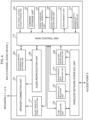
- FIG. 4 is a schematic functional configuration diagram of the multi-channel audio device 1.
- the multi-channel audio device 1 includes a wireless network interface unit 100, a speaker connection unit 101, a tune acquisition unit 102, a content storage unit 103, a test signal source sound storage unit 104, an acoustic profile information storage unit 105, an audio reproduction unit 106, an instruction receiving unit 107, a collected sound signal receiving unit 108, a noise component identifying unit 109, a noise canceling signal generating unit 110, a noise canceling signal output unit 111, a measurement data receiving unit 112, a measurement unit 113, an acoustic profile information generating unit 114, and a main control unit 115.
- the wireless network interface unit 100 is an interface for wireless connection to the access point 6.
- the speaker connection unit 101 includes, although not illustrated in FIG. 4 , for each channel, a connection terminal for connection to one of the speakers 2 that corresponds to the channel.
- the speaker connection unit 101 includes an FR channel connection terminal for connection to the speaker 2-1 corresponding to the FR channel, an FL channel connection terminal for connection to the speaker 2-2 corresponding to the FL channel, a C channel connection terminal for connection to the speaker 2-3 corresponding to the C channel, an SR connection terminal for connection to the speaker 2-4 corresponding to the SR channel, an SL channel connection terminal for connection to the speaker 2-5 corresponding to the SL channel, and an SW channel connection terminal for connection to the speaker 2-6 corresponding to the SW channel.
- the tune acquisition unit 102 accesses the media server 4 via the wireless network interface unit 100 to download a multi-channel audio signal of a tune from the media server 4.
- the content storage unit 103 stores the multi-channel audio signal of the tune which has been downloaded from the media server 4.
- the test signal source sound storage unit 104 stores the source sound of the test signal.
- the acoustic profile information storage unit 105 stores, for each channel of a multi-channel audio signal, acoustic profile information generated by the acoustic profile information generating unit 114.
- the acoustic profile information storage unit 105 stores pieces of acoustic profile information of the FR channel, the FL channel, the C channel, the SR channel, the SL channel, and the SW channel.
- the audio reproduction unit 106 reproduces, from the multi-channel audio signal stored in the content storage unit 103, audio reproduction signals of a plurality of channels (in this embodiment, the FR channel, the FL channel, the C channel, the SR channel, the SL channel, and the SW channel).
- the audio reproduction unit 106 then adjusts, for each channel, the output timing and the volume level of the audio reproduction signal in accordance with the acoustic profile information stored in the acoustic profile information storage unit 105, and outputs the audio reproduction signal via the speaker connection unit 101 from the corresponding one of the speakers 2.
- the audio reproduction unit 106 also reproduces the source sound of the test signal which is stored in the test signal source sound storage unit 104, and outputs a reproduction signal thereof via the speaker connection unit 101 from one of the speakers 2 that is designated by the main control unit 115.
- the instruction receiving unit 107 receives various instructions from the wireless terminal 3 via the wireless network interface unit 100.
- the collected sound signal receiving unit 108 receives, from the wireless terminal 3, via the wireless network interface unit 100, collected sound signals of ambient sounds at the listening point of the multi-channel audio device 1.
- the noise component identifying unit 109 identifies, as noise components, differences between the collected sound signals received by the collected sound signal receiving unit 108 and the audio reproduction signals of the respective channels that have been reproduced by the audio reproduction unit 106 and have been adjusted in output timing and volume level in accordance with the acoustic profile information.
- the noise canceling signal generating unit 110 generates noise canceling signals opposite in phase from the noise components identified by the noise component identifying unit 109.
- the noise canceling signal output unit 111 outputs the noise canceling signals generated by the noise canceling signal generating unit 110 via the speaker connection unit 101 from one of the speakers 2 that is designated by the main control unit 115.
- the measurement data receiving unit 112 receives the measurement data from the wireless terminal 3 via the wireless network interface unit 100.
- the measurement unit 113 compares the channel reproduction data and the source sound reproduction data that are included in the measurement data received by the measurement data receiving unit 112, to thereby measure a delay time and an attenuation rate of the channel reproduction data with respect to the source sound reproduction data of the designated channel that is included in the measurement data.
- the acoustic profile information generating unit 114 generates acoustic profile information on the designated channel, which includes the output timing and the volume level, based on results (the delay time and the attenuation rate of the channel reproduction data on the designated channel with respect to the source sound reproduction data) of the measurement by the measurement unit 113.
- the main control unit 115 centrally controls the units 100 to 114 of the multi-channel audio device 1.
- the functional configuration of the multi-channel audio device 1 illustrated in FIG. 4 may be implemented by hardware through use of an integrated logic IC, such as an application specific integrated circuit (ASIC) or a field programmable gate array (FPGA), or may be implemented by software through use of a computer such as a digital signal processor (DSP).
- ASIC application specific integrated circuit
- FPGA field programmable gate array
- DSP digital signal processor
- the functional configuration may be implemented on a general computer, such as a PC, including a CPU, a memory, a flash memory, a hard disk drive, or another auxiliary storage device, and a wireless communication device which is a wireless LAN adapter or the like, by the CPU by loading a predetermined program into the memory from the auxiliary storage device and executing the program.
- FIG. 5 is a flow chart for illustrating acoustic profile information setting processing of the multi-channel audio device 1.
- the instruction receiving unit 107 receives a test signal reproducing instruction from the wireless terminal 3 via the wireless network interface unit 100 (YES in Step S200), and passes the test signal reproducing instruction to the main control unit 115.
- the main control unit 115 receives the instruction, reads the source sound of the test signal out of the test signal source sound storage unit 104, and passes the source sound of the test signal along with the designated channel that is included in the test signal reproducing instruction to the audio reproduction unit 106.
- the audio reproduction unit 106 reproduces the source sound of the test signal that is received from the main control unit 115, and outputs a reproduction signal thereof via the speaker connection unit 101 from one of the speakers 2 that is a speaker of the designated channel received from the main control unit 115 (Step S201).
- the measurement data receiving unit 112 receives measurement data from the wireless terminal 3 via the wireless network interface unit 100 (Step S202), and passes the measurement data to the main control unit 115.
- the main control unit 115 passes the measurement data received from the measurement data receiving unit 112 to the measurement unit 113.
- the measurement unit 113 receives the measurement data, and compares the channel reproduction data and the source sound reproduction data that are included in the measurement data received from the main control unit 115 to each other to measure a delay time and an attenuation rate of the channel reproduction data with respect to the source sound reproduction data of the designated channel included in the measurement data (Step S203) .
- the acoustic profile information generating unit 114 generates acoustic profile information of the designated channel, which includes the reproduction timing and the volume level, based on results (the delay time and the attenuation rate of the channel reproduction data with respect to the source sound reproduction data of the designated channel) of the measurement by the measurement unit 113 (Step S204). Specifically, the reproduction timing of the designated channel is determined so that reproduction is started earlier than a standard reproduction timing by the delay time, that is, so that a start timing of the test signal in the channel reproduction data matches a start timing of the test signal in the source sound reproduction data.
- the volume level of the designated channel is determined so that the attenuation rate of the channel reproduction data of the designated channel to the source sound reproduction data is "1," that is, so that an amplitude of the test signal in the channel reproduction data matches an amplitude of the test signal in the source sound reproduction data.
- the main control unit 115 stores the acoustic profile information of the designated channel generated by the acoustic profile information generating unit 114 in the acoustic profile information storage unit 105 in association with the designated channel, to thereby set this piece of acoustic profile information as conditions under which an audio reproduction signal of this designated channel is output (Step S205).
- FIG. 6 is a flow chart for illustrating noise canceling processing of the multi-channel audio device 1.
- This flow is started by reception of a noise canceling instruction from the wireless terminal 3 when the audio reproduction unit 106 is reproducing and outputting a multi-channel audio signal.
- the main control unit 115 determines, based on pieces of acoustic profile information of the respective channels stored in the acoustic profile information storage unit 105, which of the speakers 2 is to be a noise canceling signal output destination (Step S210). Specifically, one of the speakers 2 that corresponds to a channel associated with a piece of acoustic profile information including the latest output timing, namely, one of the speakers 2 that is closest to the listening point of the multi-channel audio device 1, is determined to be the noise canceling signal output destination. In a case in which no pieces of acoustic profile information are stored for respective channels in the acoustic profile information storage unit 105, predetermined one of the speakers 2 may be determined as the noise canceling signal output destination. The main control unit 115 then notifies the one of the speakers 2 that is determined to be the noise canceling signal output destination to the noise canceling signal output unit 111.
- the collected sound signal receiving unit 108 starts reception of collected sound signals sent from the wireless terminal 3 via the wireless network interface unit 100 (Step S211).
- the main control unit 115 then sequentially outputs, to the noise component identifying unit 109, the collected sound signals sequentially received by the collected sound signal receiving unit 108, and audio reproduction signals of the respective channels that have been reproduced by the audio reproduction unit 106 and have been adjusted in output timing and volume level in accordance with the pieces of acoustic profile information.
- the noise component identifying unit 109 identifies, as noise components, differences between the collected sound signals and the audio reproduction signals of the respective channels that are sequentially input from the main control unit 115, and the noise canceling signal generating unit 110 starts generation of noise canceling signals opposite in phase from the noise components identified by the noise component identifying unit 109 (Step S212) .
- the main control unit 115 starts transmission of the noise canceling signals generated by the noise canceling signal generating unit 110 to the noise canceling signal output unit 111.
- the noise canceling signal output unit 111 starts outputting, via the speaker connection unit 101, the noise canceling signals sequentially input from the main control unit 115, to the one of the speakers 2 that is the noise canceling signal output destination, so as to superimpose the noise canceling signals on audio reproduction signals output from the one of the speakers 2 (Step S213).
- FIG. 7 is a schematic functional configuration diagram of the wireless terminal 3.
- the wireless terminal 3 includes a wireless network interface unit 300, a man-machine interface unit 301, a sound collection unit 302, a collected sound signal transmitting unit 303, a test signal source sound storage unit 304, a channel reproduction data recording unit 305, a source sound reproduction data recording unit 306, a measurement data transmitting unit 307, and a main control unit 308.
- the wireless network interface unit 300 is an interface for wireless connection to the access point 6.
- the man-machine interface unit 301 is an interface for displaying information to the user and for receiving various types of operation from the user, and includes an input/output device such as a touch panel.
- the sound collection unit 302 collects ambient sounds around its own wireless terminal 3 via a built-in microphone of its own wireless terminal 3 or a microphone connected to its own wireless terminal 3.
- the collected sound signal transmitting unit 303 transmits collected sound signals of the ambient sounds around its own wireless terminal 3 which have been collected by the sound collection unit 302, to the multi-channel audio device 1 via the wireless network interface unit 300.
- the test signal source sound storage unit 304 stores the same source sound as a source sound of a test signal output from the multi-channel audio device 1.
- the channel reproduction data recording unit 305 records a test signal that is output from one of the speakers 2 of the multi-channel audio device 1 and is collected by the sound collection unit 302, as channel reproduction data of a channel corresponding to the one of the speakers 2.
- the source sound reproduction data recording unit 306 reproduces the source sound of the test signal that is stored in the test signal source sound storage unit 304 in synchronization with start of the recording by the channel reproduction data recording unit 305, and records reproduction data thereof as source sound reproduction data.
- the measurement data transmitting unit 307 generates measurement data including the channel reproduction data recorded by the channel reproduction data recording unit 305, the source sound reproduction data recorded by the source sound reproduction data recording unit 306, and a designated channel, and transmits the measurement data to the multi-channel audio device 1 via the wireless network interface unit 300.
- the main control unit 308 centrally controls the units 300 to 307 of the wireless terminal 3.
- the functional configuration of the wireless terminal 3 that is illustrated in FIG. 7 is implemented on a portable computer including a CPU, a memory, a flash memory or another auxiliary storage device, a wireless communication device which is a wireless LAN adapter or the like, a microphone, and a speaker, such as a smartphone, a tablet PC, or a smart speaker, by the CPU by executing a predetermined program.
- a portable computer including a CPU, a memory, a flash memory or another auxiliary storage device, a wireless communication device which is a wireless LAN adapter or the like, a microphone, and a speaker, such as a smartphone, a tablet PC, or a smart speaker, by the CPU by executing a predetermined program.
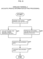
- FIG. 8 is a flow chart for illustrating acoustic profile information setting processing of the wireless terminal 3.
- This flow is started by reception of test signal reproducing operation accompanied by a designated channel from the user at the man-machine interface unit 301.
- the main control unit 308 transmits, via the wireless network interface unit 300, to the multi-channel audio device 1, a test signal reproducing instruction including the designated channel received with the test signal reproducing operation (Step S300).
- the main control unit 308 starts sound collection by the sound collection unit 302, instructs the channel reproduction data recording unit 305 to record, and instructs the source sound reproduction data recording unit 306 to reproduce and record as well.
- the channel reproduction data recording unit 305 receives the instruction and records, as channel reproduction data, a test signal that is output from one of the speakers 2 of the multi-channel audio device 1 that corresponds to the designated channel and is collected by the sound collection unit 302 (Step S301).
- the source sound reproduction data recording unit 306 reproduces, in synchronization with the start of the recording by the channel reproduction data recording unit 305, the source sound of the test signal that is stored in the test signal source sound storage unit 304, and records reproduction data thereof as source sound reproduction data (Step S302).
- the main control unit 308 passes the channel reproduction data recorded by the channel reproduction data recording unit 305 and the source sound reproduction data recorded by the source sound reproduction data recording unit 306, along with the designated channel, to the measurement data transmitting unit 307.
- the measurement data transmitting unit 307 generates measurement data including the channel reproduction data, the source sound reproduction data, and the designated channel (Step S303).
- the measurement data transmitting unit 307 transmits the measurement data to the multi-channel audio device 1 via the wireless network interface unit 300 (Step S304).
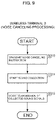
- FIG. 9 is a flow chart for illustrating noise canceling processing of the wireless terminal 3.
- This flow is started by reception of the noise canceling operation from the user at the man-machine interface unit 301 when the multi-channel audio device 1 is reproducing and outputting a multi-channel audio signal.
- the main control unit 308 transmits a noise canceling instruction to the multi-channel audio device 1 via the wireless network interface unit 300 (Step S310).
- the main control unit 308 then instructs the sound collection unit 302 to start sound collection.
- the sound collection unit 302 receives the instruction, and starts sound collection of ambient sounds at the listening point of the multi-channel audio device 1 at which its own wireless terminal 3 is placed (Step S311).
- the main control unit 308 sequentially outputs collected sound signals of the ambient sounds collected by the sound collection unit 302 to the collected sound signal transmitting unit 303.
- the collected sound signal transmitting unit 303 starts transmitting, to the multi-channel audio device 1, via the wireless network interface unit 300, the collected sound signals sequentially input from the main control unit 308 (Step S312).
- the audio reproduction signals of the respective channels output by the multi-channel audio device 1 for each channel separately from the channels' corresponding speakers 2 are collected through sound collection by the wireless terminal 3 placed at the listening point of the multi-channel audio device 1, and collected sound signals thereof are fed back to the multi-channel audio device 1.
- the multi-channel audio device 1 identifies, as noise components, differences between the collected sound signals fed back from the wireless terminal 3 and the audio reproduction signals of the respective channels output from the speakers 2-1 to 2-6, and noise canceling signals opposite in phase from the noise components are output from one of the speakers 2. Accordingly, even in an environment having noise, comfortable enjoyment of audio contents in multi-channel is accomplished by canceling the noise.
- the wireless terminal 3 provided with the recording and reproducing function such as a smartphone, a tablet PC, or a smart speaker
- the measurement microphone for generating acoustic profile information
- a dedicated measurement microphone is not required to be attached to the multi-channel audio device 1.
- the user places the wireless terminal 3 at the listening point of the multi-channel audio device 1, and the user is not required to connect the wireless terminal 3 and the multi-channel audio device 1 by a cord. Accordingly, acoustic profile information of each channel can be generated by simple operation without increasing cost.
- one of the speakers 2 that corresponds to a channel associated with a piece of acoustic profile information including the latest output timing, namely, one of the speakers 2 that is closest to the listening point of the multi-channel audio device 1, is determined to be the noise canceling signal output destination.
- a delay time until a noise canceling signal output from the one of the speakers 2 that is the noise canceling signal output destination reaches the listening point of the multi-channel audio device 1 can be shortened. This decreases a phase shift from the noise at the listening point of the multi-channel audio device 1, with the result that the noise can be canceled out more effectively.
- the embodiment described above may be modified so that which one of the speakers 2 is the noise canceling signal output destination is switchable by an instruction from the user. That is, the wireless terminal 3 transmits, to the multi-channel audio device 1, a signal for switching the noise canceling signal output destination by following noise canceling signal output destination switching operation received from the user, and the multi-channel audio device 1 receives the signal and switches the noise canceling signal output destination from one of the speakers 2 to another of the speakers 2 in a predetermined order.
- the multi-channel audio device 1 is provided with a switching button for switching the noise canceling signal output destination, and switches the noise canceling signal output destination from one of the speakers 2 to another of the speakers 2 in a predetermined order by following the user's operation of the switching button.
- the noise canceling signal output destination is determined from among the speakers 2-1 to 2-6 connected to the multi-channel audio device 1.
- the noise canceling signal output destination may be the wireless terminal 3 as long as the wireless terminal 3 includes a speaker.
- the multi-channel audio device 1 transmits a noise canceling signal to the wireless terminal 3, and the wireless terminal 3 outputs the noise canceling signal received from the multi-channel audio device 1 from the speaker.
- the wireless terminal 3 has functions as a controller for remotely operating the multi-channel audio device 1.
- a dedicated controller may be provided separately from the wireless terminal 3. That is, the controller receives various types of operation from the user and, in response, transmits various instructions to the multi-channel audio device 1.
- the multi-channel audio device 1 receives a test signal reproducing instruction from the controller
- the multi-channel audio device 1 transmits the test signal reproducing instruction to the wireless terminal 3, and starts the acoustic profile information setting processing illustrated in FIG. 5 .
- the wireless terminal 3 receives the instruction, and executes Step S301 and subsequent steps of the acoustic profile information setting processing illustrated in FIG. 8 .
- the multi-channel audio device 1 receives a noise canceling instruction from the controller, transmits the noise canceling instruction to the wireless terminal 3, and starts the noise canceling processing illustrated in FIG. 6 .
- the wireless terminal 3 receives the instruction, and executes Step S311 and subsequent steps of the noise canceling processing illustrated in FIG. 9 .
- the communication between the multi-channel audio device 1 and the wireless terminal 3 is performed via the access point 6, but the present invention is not limited thereto.
- Direct wireless communication may be performed between the multi-channel audio device 1 and the wireless terminal 3 by short-range wireless communication such as Bluetooth (trademark).
Landscapes
- Physics & Mathematics (AREA)
- Engineering & Computer Science (AREA)
- Acoustics & Sound (AREA)
- Signal Processing (AREA)
- Multimedia (AREA)
- Health & Medical Sciences (AREA)
- General Health & Medical Sciences (AREA)
- Otolaryngology (AREA)
- Circuit For Audible Band Transducer (AREA)
- Stereophonic System (AREA)
- Soundproofing, Sound Blocking, And Sound Damping (AREA)
Applications Claiming Priority (2)
| Application Number | Priority Date | Filing Date | Title |
|---|---|---|---|
| JP2020056893A JP7461771B2 (ja) | 2020-03-26 | 2020-03-26 | マルチチャンネルオーディオシステム、マルチチャンネルオーディオ装置、プログラム、およびマルチチャンネルオーディオ再生方法 |
| PCT/JP2020/036941 WO2021192367A1 (ja) | 2020-03-26 | 2020-09-29 | マルチチャンネルオーディオシステム、マルチチャンネルオーディオ装置、プログラム、およびマルチチャンネルオーディオ再生方法 |
Publications (3)
| Publication Number | Publication Date |
|---|---|
| EP4131999A1 true EP4131999A1 (de) | 2023-02-08 |
| EP4131999A4 EP4131999A4 (de) | 2024-04-24 |
| EP4131999B1 EP4131999B1 (de) | 2026-04-01 |
Family
ID=77890235
Family Applications (1)
| Application Number | Title | Priority Date | Filing Date |
|---|---|---|---|
| EP20927835.7A Active EP4131999B1 (de) | 2020-03-26 | 2020-09-29 | Mehrkanaliges audiosystem, mehrkanalige audiovorrichtung, programm und mehrkanaliges audiowiedergabeverfahren |
Country Status (4)
| Country | Link |
|---|---|
| US (1) | US12356160B2 (de) |
| EP (1) | EP4131999B1 (de) |
| JP (1) | JP7461771B2 (de) |
| WO (1) | WO2021192367A1 (de) |
Families Citing this family (2)
| Publication number | Priority date | Publication date | Assignee | Title |
|---|---|---|---|---|
| JP2024025259A (ja) * | 2022-08-11 | 2024-02-26 | 株式会社ディーアンドエムホールディングス | オーディオシステム、オーディオ装置、プログラム、およびオーディオ再生方法 |
| KR20250075364A (ko) * | 2023-11-21 | 2025-05-28 | 삼성전자주식회사 | 전자 장치 및 그 제어 방법 |
Family Cites Families (12)
| Publication number | Priority date | Publication date | Assignee | Title |
|---|---|---|---|---|
| JP2000354300A (ja) | 1999-06-11 | 2000-12-19 | Accuphase Laboratory Inc | マルチチャンネルオーディオ再生装置 |
| IL134979A (en) * | 2000-03-09 | 2004-02-19 | Be4 Ltd | A system and method for optimizing three-dimensional hearing |
| JP2002367290A (ja) | 2001-06-12 | 2002-12-20 | Sony Corp | オーディオ再生装置及びオーディオ再生方法 |
| KR100677119B1 (ko) * | 2004-06-04 | 2007-02-02 | 삼성전자주식회사 | 와이드 스테레오 재생 방법 및 그 장치 |
| JP4232775B2 (ja) * | 2005-11-11 | 2009-03-04 | ソニー株式会社 | 音場補正装置 |
| JP4862448B2 (ja) * | 2006-03-27 | 2012-01-25 | 株式会社Jvcケンウッド | オーディオシステム、携帯型情報処理装置、オーディオ装置及び音場補正方法 |
| US8385557B2 (en) * | 2008-06-19 | 2013-02-26 | Microsoft Corporation | Multichannel acoustic echo reduction |
| US9020158B2 (en) * | 2008-11-20 | 2015-04-28 | Harman International Industries, Incorporated | Quiet zone control system |
| US8135140B2 (en) | 2008-11-20 | 2012-03-13 | Harman International Industries, Incorporated | System for active noise control with audio signal compensation |
| EP2823650B1 (de) * | 2012-08-29 | 2020-07-29 | Huawei Technologies Co., Ltd. | Audiowiedergabesystem |
| EP3040984B1 (de) * | 2015-01-02 | 2022-07-13 | Harman Becker Automotive Systems GmbH | Schallzonenanordnung mit zonenweiser sprachunterdrückung |
| US10229698B1 (en) * | 2017-06-21 | 2019-03-12 | Amazon Technologies, Inc. | Playback reference signal-assisted multi-microphone interference canceler |
-
2020
- 2020-03-26 JP JP2020056893A patent/JP7461771B2/ja active Active
- 2020-09-29 US US17/906,290 patent/US12356160B2/en active Active
- 2020-09-29 EP EP20927835.7A patent/EP4131999B1/de active Active
- 2020-09-29 WO PCT/JP2020/036941 patent/WO2021192367A1/ja not_active Ceased
Also Published As
| Publication number | Publication date |
|---|---|
| JP2021158526A (ja) | 2021-10-07 |
| US12356160B2 (en) | 2025-07-08 |
| WO2021192367A1 (ja) | 2021-09-30 |
| US20230101944A1 (en) | 2023-03-30 |
| JP7461771B2 (ja) | 2024-04-04 |
| EP4131999B1 (de) | 2026-04-01 |
| EP4131999A4 (de) | 2024-04-24 |
Similar Documents
| Publication | Publication Date | Title |
|---|---|---|
| US20200236463A1 (en) | Headphone device, terminal device, information transmitting method, program, and headphone system | |
| US9961444B2 (en) | Reproducing device, headphone and reproducing method | |
| JP5973465B2 (ja) | オーディオ処理デバイス | |
| US20160212535A1 (en) | System and method for controlling output of multiple audio output devices | |
| US20160234589A1 (en) | Audio apparatus and methods | |
| EP3248397A1 (de) | Systeme und verfahren zur steuerung des ausgangs mehrerer audioausgangsvorrichtungen | |
| EP2816823B1 (de) | Audiosystem und Audiovorrichtung und Kanalmapping-Verfahren dafür | |
| CN108111952B (zh) | 一种录音方法、装置、终端及计算机可读存储介质 | |
| KR20200017702A (ko) | 외부 전자 장치와의 거리에 기반하여 스피커의 출력 세기를 조정하기 위한 방법 및 전자 장치 | |
| CN112637732A (zh) | 显示装置以及音频信号的播放方法 | |
| EP4131999A1 (de) | Mehrkanaliges audiosystem, mehrkanalige audiovorrichtung, programm und mehrkanaliges audiowiedergabeverfahren | |
| US20180082672A1 (en) | Information processing apparatus and information processing method thereof | |
| JP6777185B2 (ja) | 端末装置、ヘッドホンシステム、ノイズキャンセルモードによる外部ヘッドホン制御方法 | |
| US20210272579A1 (en) | Audio signal processing device | |
| JP6873549B2 (ja) | オーディオ装置およびコンピュータで読み取り可能なプログラム | |
| CN113611272A (zh) | 基于多移动终端的扬声方法、装置及存储介质 | |
| JP2021164151A (ja) | 集音装置 | |
| JP2007124380A (ja) | 立体音響出力システム、立体音響出力方法及び立体音響出力用プログラム | |
| EP4571731A1 (de) | Audiosystem, audiovorrichtung, programm und audiowiedergabeverfahren | |
| EP4068808B1 (de) | Mehrkanal-audiosystem, vorrichtung zum erzeugen akustischer profilinformationen, drahtlose aufnahme- und wiedergabevorrichtung, programm und verfahren zum erzeugen akustischer profilinformationen | |
| CN219395046U (zh) | 主动降噪耳机的测试系统 | |
| JP2011095703A (ja) | オーディオ再生システム及び方法 | |
| KR100775277B1 (ko) | 음향 처리 기능을 갖는 이동 통신 단말기 | |
| KR101448247B1 (ko) | 음압 측정장치 및 그 동작방법 | |
| JP2019212993A (ja) | 音響プロファイル情報生成装置、コントローラ、マルチチャンネルオーディオ装置、およびコンピュータで読み取り可能なプログラム |
Legal Events
| Date | Code | Title | Description |
|---|---|---|---|
| STAA | Information on the status of an ep patent application or granted ep patent |
Free format text: STATUS: THE INTERNATIONAL PUBLICATION HAS BEEN MADE |
|
| PUAI | Public reference made under article 153(3) epc to a published international application that has entered the european phase |
Free format text: ORIGINAL CODE: 0009012 |
|
| STAA | Information on the status of an ep patent application or granted ep patent |
Free format text: STATUS: REQUEST FOR EXAMINATION WAS MADE |
|
| 17P | Request for examination filed |
Effective date: 20220926 |
|
| AK | Designated contracting states |
Kind code of ref document: A1 Designated state(s): AL AT BE BG CH CY CZ DE DK EE ES FI FR GB GR HR HU IE IS IT LI LT LU LV MC MK MT NL NO PL PT RO RS SE SI SK SM TR |
|
| DAV | Request for validation of the european patent (deleted) | ||
| DAX | Request for extension of the european patent (deleted) | ||
| REG | Reference to a national code |
Ref country code: DE Ref legal event code: R079 Free format text: PREVIOUS MAIN CLASS: H04R0003000000 Ipc: H04S0007000000 Ref country code: DE Ref legal event code: R079 Ref document number: 602020069838 Country of ref document: DE Free format text: PREVIOUS MAIN CLASS: H04R0003000000 Ipc: H04S0007000000 |
|
| A4 | Supplementary search report drawn up and despatched |
Effective date: 20240325 |
|
| RIC1 | Information provided on ipc code assigned before grant |
Ipc: H04R 5/04 20060101ALI20240319BHEP Ipc: G10K 11/178 20060101ALI20240319BHEP Ipc: H04S 7/00 20060101AFI20240319BHEP |
|
| GRAP | Despatch of communication of intention to grant a patent |
Free format text: ORIGINAL CODE: EPIDOSNIGR1 |
|
| STAA | Information on the status of an ep patent application or granted ep patent |
Free format text: STATUS: GRANT OF PATENT IS INTENDED |
|
| INTG | Intention to grant announced |
Effective date: 20251117 |
|
| GRAS | Grant fee paid |
Free format text: ORIGINAL CODE: EPIDOSNIGR3 |
|
| GRAA | (expected) grant |
Free format text: ORIGINAL CODE: 0009210 |
|
| STAA | Information on the status of an ep patent application or granted ep patent |
Free format text: STATUS: THE PATENT HAS BEEN GRANTED |
|
| AK | Designated contracting states |
Kind code of ref document: B1 Designated state(s): AL AT BE BG CH CY CZ DE DK EE ES FI FR GB GR HR HU IE IS IT LI LT LU LV MC MK MT NL NO PL PT RO RS SE SI SK SM TR |
|
| REG | Reference to a national code |
Ref country code: CH Ref legal event code: F10 Free format text: ST27 STATUS EVENT CODE: U-0-0-F10-F00 (AS PROVIDED BY THE NATIONAL OFFICE) Effective date: 20260401 Ref country code: GB Ref legal event code: FG4D |
|
| P01 | Opt-out of the competence of the unified patent court (upc) registered |
Free format text: CASE NUMBER: UPC_APP_0009637_4131999/2026 Effective date: 20260311 |
|
| REG | Reference to a national code |
Ref country code: IE Ref legal event code: FG4D |
|
| REG | Reference to a national code |
Ref country code: DE Ref legal event code: R096 Ref document number: 602020069838 Country of ref document: DE |