EP4131920B1 - Dispositif et procédé de génération d'une image stéréo photométrique et d'une image couleur - Google Patents
Dispositif et procédé de génération d'une image stéréo photométrique et d'une image couleur Download PDFInfo
- Publication number
- EP4131920B1 EP4131920B1 EP22186178.4A EP22186178A EP4131920B1 EP 4131920 B1 EP4131920 B1 EP 4131920B1 EP 22186178 A EP22186178 A EP 22186178A EP 4131920 B1 EP4131920 B1 EP 4131920B1
- Authority
- EP
- European Patent Office
- Prior art keywords
- lighting
- illumination
- pulses
- wavelength range
- sensor arrangement
- Prior art date
- Legal status (The legal status is an assumption and is not a legal conclusion. Google has not performed a legal analysis and makes no representation as to the accuracy of the status listed.)
- Active
Links
Images


Classifications
-
- H—ELECTRICITY
- H04—ELECTRIC COMMUNICATION TECHNIQUE
- H04N—PICTORIAL COMMUNICATION, e.g. TELEVISION
- H04N23/00—Cameras or camera modules comprising electronic image sensors; Control thereof
- H04N23/56—Cameras or camera modules comprising electronic image sensors; Control thereof provided with illuminating means
-
- H—ELECTRICITY
- H04—ELECTRIC COMMUNICATION TECHNIQUE
- H04N—PICTORIAL COMMUNICATION, e.g. TELEVISION
- H04N13/00—Stereoscopic video systems; Multi-view video systems; Details thereof
- H04N13/20—Image signal generators
- H04N13/204—Image signal generators using stereoscopic image cameras
- H04N13/254—Image signal generators using stereoscopic image cameras in combination with electromagnetic radiation sources for illuminating objects
-
- H—ELECTRICITY
- H04—ELECTRIC COMMUNICATION TECHNIQUE
- H04N—PICTORIAL COMMUNICATION, e.g. TELEVISION
- H04N13/00—Stereoscopic video systems; Multi-view video systems; Details thereof
- H04N13/10—Processing, recording or transmission of stereoscopic or multi-view image signals
- H04N13/106—Processing image signals
- H04N13/15—Processing image signals for colour aspects of image signals
-
- H—ELECTRICITY
- H04—ELECTRIC COMMUNICATION TECHNIQUE
- H04N—PICTORIAL COMMUNICATION, e.g. TELEVISION
- H04N13/00—Stereoscopic video systems; Multi-view video systems; Details thereof
- H04N13/20—Image signal generators
- H04N13/204—Image signal generators using stereoscopic image cameras
- H04N13/207—Image signal generators using stereoscopic image cameras using a single 2D image sensor
-
- H—ELECTRICITY
- H04—ELECTRIC COMMUNICATION TECHNIQUE
- H04N—PICTORIAL COMMUNICATION, e.g. TELEVISION
- H04N13/00—Stereoscopic video systems; Multi-view video systems; Details thereof
- H04N13/20—Image signal generators
- H04N13/257—Colour aspects
-
- H—ELECTRICITY
- H04—ELECTRIC COMMUNICATION TECHNIQUE
- H04N—PICTORIAL COMMUNICATION, e.g. TELEVISION
- H04N23/00—Cameras or camera modules comprising electronic image sensors; Control thereof
- H04N23/60—Control of cameras or camera modules
Definitions
- the present invention relates to an apparatus and a method for generating photometric stereo images and a color image of an object moving relative to an image sensor arrangement.
- the objects can be one or more products.
- images of the products are often taken and evaluated to determine whether the respective product complies with specified product specifications.
- the product specifications can, for example, set requirements for the surface finish of the products. It is often necessary, for example, to exclude the presence of bumps or scratches. In other applications, it may be required that an embossed pattern applied to the products is completely and properly embossed.
- photometric stereo images such as inclination images, texture images, curvature images, gradient images or height images, such three-dimensional or spatially distinct features of objects can be made clearly visible and therefore easier to examine.
- Product specifications often also include specifications for two-dimensional or two-dimensional features, such as color. For example, unwanted discoloration must be detected or the color of a print on the objects must be ensured to match that of a print template. For this purpose, color images of the objects must be taken. Color sensors or color cameras are usually used for this purpose, but these are disadvantageous mainly due to their relatively high acquisition costs.
- a device for generating photometric stereo images and a color image is known, for example, from the US 2018 / 0328855 A1
- a method for determining geometric errors in surface detection is known.
- the present invention is therefore based on the object of creating possibilities that allow images of the type mentioned at the outset to be generated at low cost, in particular without the use of color sensors or color cameras.
- the object is achieved according to the invention by a device for generating photometric stereo images and the color image as defined in the appended claim 1.
- the device according to the invention can be used to generate photometric stereo illumination by means of the different illumination directions of the illumination pulses, which simultaneously enables color differentiation due to the different wavelength ranges of the illumination pulses.
- the device preferably comprises an image data processor for calculating photometric stereo images and a color image of an object moving at a predetermined relative speed relative to an image sensor arrangement with a predetermined sensor geometry, wherein the image data processor is designed to calculate the photometric stereo images and the color image from at least four image data sets, wherein at least three of the image data sets represent brightness values of different locations of a region of the object illuminated in different wavelength ranges, and wherein at least two of the image data sets represent brightness values of these locations of the object illuminated from different illumination directions, wherein the image data processor is designed to calculate brightness values of individual pixels of the same location of the object region as a multi-colored pixel tuple from the image data sets with different illumination directions, based on sensor data representing the sensor geometry and speed values representing the relative speed, from the image data sets with different wavelength ranges, and from the image data sets with different illumination directions, brightness values of individual pixels of the same location of the object region as a multi-directional pixel tuple.
- the image data processor is designed to generate a pixel of the color image based on each multi-colored pixel tuple and the wavelength ranges and to generate a pixel of a photometric stereo image based on each multi-directional pixel tuple and the illumination directions.
- the brightness values of the image data sets are in particular brightness values or intensity values measured by pixels of the image sensor arrangement.
- each image data set contains brightness values or intensity values measured by pixels of the image sensor arrangement under illumination in a predetermined wavelength range from a predetermined illumination direction, with at least three of the image data sets differing in the wavelength ranges represented therein and with at least two of the image data sets differing in the illumination directions represented therein.
- the specific information about the different wavelength ranges and illumination directions does not have to come from the image sensor arrangement, since it is sufficient if this information can only be assigned to the image data sets and in particular to the brightness values contained therein.
- the pixels of the color image can still be reconstructed as follows.
- the brightness value of an individual pixel of each multi-colored pixel tuple necessarily corresponds to the brightness value of a corresponding pixel of a color channel of the color image if the color channel represents the said wavelength range.
- the superposition of the pixels of the color channels of all the different wavelength ranges represented in the image data sets from one and the same multi-colored pixel tuple reconstructed in this way consequently results in the complete pixel of the color image.
- the entire color image results from the totality of the pixels generated.
- the system of equations reflects the qualitative relationship that an object surface facing a light source reflects more light and therefore appears brighter to an observer (here: image sensor arrangement) than an object surface facing away from that light source. Object surfaces that are sideways to the light source have a correspondingly medium brightness.
- a sufficient number of linearly independent equations of the system of equations can be set up, the solution set of which determines the surface normal.
- a difference image can be generated from just two illumination directions, which makes many topological defects in a certain orientation visible. By calculating further difference images with other combinations of directions, all defects in all orientations can finally be detected.
- a color value or a gray value can be assigned to the orientation of the surface normal calculated for the respective multidirectional pixel tuple.
- This color value or gray value corresponds to the color value or gray value of the pixel in the photometric stereo image.
- An entire photometric stereo image results from all pixels generated in this way.
- the present invention therefore has the advantage that both photometric stereo images and the color image can be calculated using recorded monochromatic brightness values. This means that no color sensor or color camera is required. The cost is correspondingly low if the image data processor is used to generate photometric stereo images and the color image.
- a method for generating the photometric stereo image and the color image also solves the problem set out at the outset, the method being defined in the appended claim 6.
- the wavelength ranges can be continuous, interrupted and/or formed from individual spectral lines.
- the illumination directions describe the spatial directions in which the respective illumination pulses propagate towards the illumination area.
- the image data processor can be designed to read the image data sets directly from the image sensor arrangement after they have been recorded there. Additionally or alternatively, the image data processor can be designed to read the image data sets from the storage medium. Accordingly, the image data sets can be stored or temporarily stored on the storage medium. If required, a temporal decoupling between the recording of the image data sets and the calculation of the images can thus advantageously be achieved.
- the illumination sequence can also have more than four illumination pulses.
- at least two illumination pulses from different illumination directions can have the same wavelength range.
- the photometric stereo method used is thus less susceptible to distortion due to absorption of the illumination pulses.
- the measured brightness values are based purely on the orientation of the object surface and are not influenced by the color of the object surface.
- At least two illumination pulses of different wavelength ranges can have the same illumination direction.
- the wavelength ranges of the illumination pulses can cover an RGB color space.
- each of the Wavelength ranges represent or form a portion of the RGB color space.
- the wavelength ranges can therefore be the wavelength ranges of red light, green light and blue light. This design is advantageously suitable for the generation of RGB color images.
- the wavelength ranges can also correspond to UV radiation and/or IR radiation.
- the color image to be calculated can then be a multispectral image in false color representation, in particular a multispectral image or a hyperspectral image.
- At least one illumination pulse can form a light sheet or a light disk.
- the illumination pulses can be designed as light sheets or light disks directed at the illumination area.
- the illumination pulses can thus be distributed as homogeneously as possible over the illumination area.
- the device has a monochromatic image sensor arrangement with a recording area, wherein the recording area of the image sensor arrangement and the illumination area overlap, and wherein the image sensor arrangement is designed to measure brightness values in the recording area during each illumination pulse.
- this embodiment is advantageously characterized by particularly low acquisition costs.
- the method step of illuminating comprises the steps of emitting an illumination pulse in a first wavelength range from a first illumination direction, from a second illumination direction, from a third illumination direction and from a fourth illumination direction, emitting an illumination pulse in a second wavelength range from each of the first, second, third and fourth illumination directions and emitting an illumination pulse in a third wavelength range from each of the first, second, third and fourth illumination directions, wherein the first, second and third wavelength ranges are not congruent with one another and wherein the first, second, third and fourth illumination directions are not parallel to one another.
- these steps are repeated periodically.
- the illumination pulses can be emitted from more than four different illumination directions.
- the illumination pulses can be emitted individually one after the other and each generate a one-sided illumination constellation.
- a two-sided illumination constellation or a multi-sided diffuse illumination constellation can result. This is explained below.
- At least two illumination pulses in the same wavelength range can be emitted simultaneously and generate the two-way illumination constellation.
- Vectors representing the illumination directions of these two illumination pulses preferably have two spatial components directed in the same direction and one spatial component directed in the opposite direction.
- At least two further illumination pulses in this same wavelength range can also be emitted simultaneously and generate yet another two-way illumination constellation.
- the previously mentioned multi-sided diffuse lighting constellation is created, for example, when four lighting pulses in the same wavelength range are emitted simultaneously.
- Vectors representing the lighting directions of these four lighting pulses have only one spatial component in the same direction and two spatial components in the opposite direction for two of the four lighting pulses.
- four further lighting pulses in the same wavelength range can also be emitted simultaneously and the remaining lighting pulses can be emitted one after the other.
- the multi-sided diffuse lighting constellation for the latter can be reconstructed mathematically afterwards by averaging the brightness values measured during the lighting pulses emitted one after the other.
- the multi-sided diffuse lighting configuration provides uniform lighting conditions for recording the brightness values for the color image.
- the one-sided or two-sided lighting configurations are mainly used to record the brightness values for a photometric stereo image.
- a tilt image, a texture image, a curvature image, a gradient image and/or a height image can be calculated as a photometric stereo image.
- the inclination images, texture images, curvature images, gradient images and height images can also be converted into one another by numerical integration or differentiation.
- the device according to the invention can have the image data processor already mentioned and thus advantageously fulfill its function without further additional devices. Additionally or alternatively, the device can also be designed to be connectable to the computer already mentioned above.
- the image data processor can be designed to read out the brightness values from the image sensor arrangement as image data sets after each illumination pulse and to assign the wavelength range and the illumination direction of this illumination pulse to each brightness value.
- the image sensor arrangement has at least four pixel fields spaced apart from one another at a predetermined spatial distance, wherein the time interval between two successive illumination pulses of the illumination sequence is equal to the time during which an image of the object projected onto the image sensor arrangement advances by the relative speed by a distance which corresponds to the spatial distance between two adjacent pixel fields.
- the object moves in a straight line and the pixel fields are arranged exactly one behind the other with respect to the direction of movement of the object. This means that every point on the object that is photographed by the first pixel field is also photographed by all pixel fields arranged behind it.
- the temporal distance corresponds to a time span and/or a time duration that is calculated from the pixel spacing on the object and the relative speed of the moving object to the image sensor arrangement.
- the illumination arrangement is designed such that the time interval between two consecutive illumination pulses of the illumination sequence is selected such that a specific object area is imaged sequentially onto the at least four pixel fields. This advantageously ensures pixel synchronicity, whereby the measurement values generated are comparable.
- the pixel fields of the image sensor array can, for example, be pixel rows. Accordingly, the spatial distance represents a line spacing between the pixel rows.
- the image sensor arrangement can have at least one pixel row for each different lighting constellation resulting from the lighting sequence. This ensures that for each multi-colored pixel tuple, a multi-directional pixel tuple can also be recorded that images the same location on the object.
- the image sensor arrangement can be designed, for example, as a multi-line line camera or a matrix camera that can be read line by line.
- a combination of several such cameras can also form the image sensor arrangement.
- the number of pixel rows of the image sensor arrangement can also be smaller than the number of different lighting constellations resulting from the lighting sequence.
- the pixel synchronicity already defined above can still be achieved with sufficient accuracy.
- the brightness values for one lighting constellation each must be recorded "between" the existing pixel rows.
- the time interval to the lighting pulse of the previous lighting constellation must be smaller than the time during which the image of the object projected onto the image sensor arrangement advances by the distance due to the relative speed, which corresponds to the line spacing of two adjacent pixel rows.
- the image sensor array may have only two pixel rows while the illumination array emits an illumination sequence with four different illumination constellations.
- the image sensor array may have four pixel rows while the illumination array emits an illumination sequence with six different illumination constellations.
- the number of pixel rows and illumination sequences is in principle variable, whereby in each case the number of pixel rows is smaller than the number of illumination sequences.
- the time interval between two consecutive lighting pulses must be smaller, at least in two lighting configurations, than the time during which the The image of the object projected by the image sensor arrangement is advanced by the distance corresponding to the spatial distance between two adjacent pixel rows due to the relative speed.
- the brightness values for these lighting constellations must therefore be recorded "between" the pixel rows.
- the offset between the two shortened pixel rows is, for example, 50%, optionally less than 25%, preferably less than 10% of the pixel width of an individual pixel of the image sensor arrangement.
- the brightness values can be additionally approximated by interpolation or averaging of two pixel rows.
- the pixel synchronicity mentioned above can be sufficiently achieved if the "interposed" lighting constellations are generated as close as possible to the previous lighting constellation and the brightness values are measured immediately. In this case, this means that many "interposed" lighting constellations are generated while the image of the object projected onto the image sensor arrangement advances by the distance that corresponds to the line spacing of two adjacent pixel rows due to the relative speed.
- the above-mentioned linear movement of the object can be generated, for example, by a conveyor device.
- the device according to the invention can have the conveyor device.
- the method according to the invention comprises the steps (if necessary, controlling the conveyor device) of moving the object through the illumination area and through the recording area of the monochromatic image sensor arrangement and recording the brightness values in the recording area during each illumination pulse. This embodiment enables continuous recordings, so that it is particularly suitable for applications with elongated or continuous objects.
- the relative speed and sensor geometry are preferably constant.
- the speed values and/or the sensor data can change over time.
- the image data processor can be designed to read or receive the speed values and the sensor data, for example, via one or more interfaces.
- the method according to the invention provides that a monochromatic image sensor arrangement with at least four pixel fields spaced apart from one another at a predetermined spatial distance is provided, wherein the time interval between two successive illumination pulses of the illumination sequence is selected to be less than or equal to the time during which an image of the object projected onto the image sensor arrangement advances by the relative speed by a distance that corresponds to the spatial distance between two adjacent pixel fields.
- an image data processor 1 is described with reference to Fig. 1
- exemplary embodiments of a device 2 according to the invention are described with reference to Fig. 2 and 3 described.
- some aspects of the invention are only described in the context of a device, it is of course possible that these aspects also represent a description of the corresponding method, wherein, for example, a block, a module, a unit or a device corresponds to a method step or a function of a method step.
- aspects that are described in the context of a method step also represent a description of a block, a module, a unit or a property of the device.
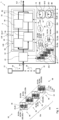
- Fig. 1 is a highly simplified, schematic representation of an exemplary embodiment of the image data processor 1.
- the image data processor 1 can have a separate processor board 4 and/or be mounted on a board (not shown) of the device 2 (see Fig. 2 and 3 ).
- the blocks, modules and units of the image data processor 1 described below can each be implemented in hardware, software or in a combination of both.
- the image data processor 1 is designed to calculate photometric stereo images 6 and a color image 8 from a monochromatic image sensor arrangement 12 (see Fig. 2 and 3 ) with a predetermined sensor geometry moving object 14.
- the image data processor 1 is designed to calculate the photometric stereo images 6 and the color image 8 from at least four image data sets 18 in an image calculation unit 16. This is explained in more detail below.
- Fig. 1 On the left, it is indicated for the image data sets 18 that these can be read out, for example, directly from monochromatic pixels 20 of the image sensor arrangement 12 after they have been recorded there one after the other, as will be explained further below.
- the image data sets 18 can also be stored on a storage medium 22 and read out from this.
- the image data processor 1 can have a corresponding readout unit 24 and a readout interface 26.
- the image data sets 18 contain, according to the invention, monochromatic gray values that represent brightness values 28 of different locations in an area of the object 14. At least three of the image data sets 18 represent brightness values 28 of the object 14 illuminated in different wavelength ranges 30. Such image data sets 18 are in Fig. 1 exemplified as image data set group 32a. At least two of the image data sets 18 represent brightness values 28 of the object 14 illuminated from different illumination directions 34. Such image data sets 18 are in Fig. 1 exemplified as image data set group 32b.
- each image data set 18 contains brightness values 28 measured by the image sensor arrangement 12 at different locations on the object 14 under illumination in a predetermined wavelength range 30 from a predetermined illumination direction 34, wherein at least three of the image data sets 18 differ in the wavelength ranges 30 represented therein (ie image data set group 32a) and wherein at least two of the image data sets 18 differ in the illumination directions 34 represented therein (ie image data set group 32b).
- the same image data sets 18 can belong to the image data set group 32a and 32b at the same time.
- the different wavelength ranges 30 can be, for example, the wavelength ranges of red light 36, green light 38 and blue light 40. Accordingly, the wavelength ranges 30 used for the illumination can cover an RGB color space and the color image 8 to be calculated can be an RGB color image 42. Additionally or alternatively, UV radiation and/or IR radiation can also be used for the illumination.
- the color image 8 to be calculated can then be a multispectral image in false color representation, in particular a multispectral image or a hyperspectral image.
- the different illumination directions 34 can result from a one-sided illumination constellation 44, a two-sided illumination constellation 46 or a multi-sided diffuse illumination constellation 48.
- the one-sided or two-sided illumination constellations 44, 46 are mainly used to record the brightness values 28 for the photometric stereo image 6.
- an inclination image, a texture image, a curvature image, a gradient image and/or a height image can be calculated as the photometric stereo image 6.
- the multi-sided diffuse illumination constellation 48 provides uniform illumination conditions for recording the brightness values 28 for the color image 8.
- the image data processor 1, in particular the readout unit 24, can be designed to assign the associated wavelength range 30 and the associated illumination direction 34 to each brightness value 28.
- the image data sets 18 are shown in Fig. 1 the brightness values 28 are assigned to the individual pixels 20 of the image sensor arrangement 12 from which they were recorded and together with the entire object 14, the different wavelength ranges 30 and the different illumination directions 34.
- These are top views 50 of the object 14 from the perspective of the image sensor arrangement 12.
- the respective illumination constellation 44, 46, 48 is indicated in the top views 50 by arrows, with different arrow directions representing different illumination directions 34, while different arrow lines (e.g. dot-dash, solid line, thick line) represent the different wavelength ranges 30.
- the brightness values 28 of the image data sets 18 can be measured by the image sensor arrangement 12 using an electronic shutter. Accordingly, it can be seen that the image sensor arrangement with which the image data sets 18 are recorded has four pixel rows 52a, 52b, 52c, 52d.
- the sensor geometry already mentioned above is in this case mainly defined by the mutual spatial distance 54 of the pixel rows 52a, 52b, 52c, 52d (i.e. line spacing 124).
- the image data processor 1 is further designed to identify brightness values 28 of individual pixels 20 of the same location of the object area based on the spatial distance 54 and on the speed values 56 representing the relative speed 10 from the image data sets 18 with different wavelength ranges 30, in particular from the respective image data set groups 32a, and to combine them as a multi-colored pixel tuple 58 (see thought bubble 202 in Fig. 1 ).
- the image data processor 1 is designed to identify brightness values of individual pixels 20 of the same location of the object area based on the spatial distance 54 and the speed values 56 from the image data sets 18 with different illumination directions 34, in particular from the respective image data set groups 32b, and to combine them as a multidirectional pixel tuple 60 (see thought bubble 203 in Fig. 1 ).
- the image calculation unit 16 can have a pixel tuple identification module 62 with a block 64 for identifying and combining multi-colored pixel tuples 58 and a block 66 for identifying and combining multi-directional pixel tuples 60.
- Each multi-colored pixel tuple 58 is a tuple of length n and contains as elements the brightness values 28 from the image data sets 18 with different wavelength ranges 30 that were measured by pixels of the image sensor arrangement 12 at one and the same location in the object area, wherein the length n corresponds to the number of different wavelength ranges 30.
- each multi-directional pixel tuple 60 is a tuple of length m and contains as elements the brightness values 28 from the image data sets 18 with different illumination directions 34, which were measured by pixels of the image sensor arrangement 12 at one and the same location in the object area, wherein the length m corresponds to the number of different illumination directions 34.
- the image data sets 18 are recorded in such a way that for each multi-colored pixel tuple 58 there is also a multi-directional pixel tuple 60 that depicts the same location of the object area, and vice versa. This is explained in more detail below in connection with the device 2 according to the invention and enables the generation of pixel synchronicity between the color components of the color image 8 and the photometric stereo image 6.
- the brightness values 28 of each multi-colored pixel tuple 58 can, for example, be uniquely assignable to a wavelength range 30 by their arrangement within the pixel tuple 58. Accordingly, the brightness values 28 of each multi-directional pixel tuple 60 can be uniquely assigned to an illumination direction 34 by their arrangement within the pixel tuple 60. This is shown in Fig. 1 purely exemplary for pixel tuples 58, 60 with three/two elements 70 (see thought bubbles 202, 203). The multi-colored pixel tuples 58 and the multi-directional pixel tuples 60 can of course differ in their number of elements 70.
- the image data processor 1 is further designed to generate a pixel 72 of the color image 8 based on each multi-colored pixel tuple 58 and the wavelength ranges 30, in particular the wavelength ranges 30 of the multi-sided diffuse illumination constellations 48 (see thought bubble 204 in Fig. 1 ). Since all brightness values 28, as already described above, are only present as monochromatic gray values, but can be assigned to a wavelength range 30, the pixel 72 of the color image 8 can be reconstructed as follows.
- the brightness value 28 of an element 70 of the multi-colored pixel tuple 58 in combination with the associated wavelength range 30 corresponds to the brightness value 28 of a pixel 74 of a color channel of the color image 8, whereby the color channel reproduces this wavelength range 30.
- the image data processor 1 is designed to generate a pixel 76 of the photometric stereo image 6 based on each multidirectional pixel tuple 60 and the illumination directions 34, in particular the illumination directions 34 of the directed illumination constellations 44, 46 (see thought bubble 205 in Fig. 1 ).
- the so-called photometric stereo method is used, which is known to the person skilled in the art from the prior art and is therefore only explained in part below.
- the brightness value 28 of each element 70 of the multidirectional pixel tuple 60 and the associated illumination direction 34 are inserted according to the photometric stereo method into an equation of a system of equations for calculating a surface normal at the location of the object area that the pixel tuple 60 depicts.
- the system of equations reflects the qualitative relationship that an object surface facing a directed light source reflects more light and therefore appears brighter to an observer (here: image sensor arrangement 12) than an object surface facing away from this light source. Object surfaces that are laterally positioned to the light source have an average brightness. With enough elements 70 in the pixel tuple 60, a sufficient number of linearly independent equations of the system of equations can be set up, the solution set of which determines the surface normal.
- a color value or a gray value 78 can be assigned to the orientation of the surface normal calculated for the pixel tuple 60. This color value or gray value 78 then corresponds to the color value or gray value 80 of the pixel 76.
- the entire photometric stereo image 6 results from the totality of the pixels 76 generated in this way (see thought bubble 207 in Fig. 1 ).
- the image calculation unit 16 can have a pixel generation module 82 with a block 84 for generating the pixels 72 of the color image 8 and a block 86 for generating the pixels 76 of the photometric stereo image 6. Due to the pixel synchronicity already mentioned, the color image 8 and the photometric stereo image 6 can optionally be combined in the image calculation unit 16 to form a photometric stereo color image.
- the image data processor 1 can have an internal data memory 88, which is designed to store or temporarily store intermediate results of the process steps running in the image data processor 1.
- the thought bubbles 201, 202, 203, 204, 205, 206 and 207 Fig. 1 are intended to merely represent a symbol of the process steps taking place in the image data processor 1. Their placement in the area of the data memory 88 is due to space reasons and is not intended to mean that such a graphic reproduction must take place in the image data processor 1 or in the data memory 88.
- Fig. 2 and 3 show schematic representations of exemplary embodiments of the device 2 according to the invention, which has the image sensor arrangement 12 already mentioned above and an illumination arrangement 90.
- the structure and function of the illumination arrangement 90 are described below with reference to Fig. 2 in which the image sensor arrangement 12 is shown only in a very simplified manner.
- the image sensor arrangement 12 is again described with reference to Fig. 3 in which, for reasons of better clarity, the lighting arrangement 90 is only shown in a highly simplified manner.
- the device 2 serves to generate the photometric stereo image 6 and the color image 8.
- the lighting arrangement 90 of the device 2 serves to generate the lighting constellations 44, 46, 48 and the image sensor arrangement 12 of the device 2 serves to record the brightness values 28 for the image data sets 18.
- the device 2 can also have a conveyor device 92, for example a conveyor belt 94, on which the object 14 can be moved relative to the device 2, in particular relative to the image sensor arrangement 12.
- the device 2, in particular the image sensor arrangement 12 can also be designed to be movable relative to the object 14.
- the lighting arrangement 90 is directed towards a lighting area 96 and is designed to cyclically emit a lighting sequence 98 into the lighting area 96.
- the lighting sequence 98 has at least four lighting pulses 100, which are preferably repeated periodically, with each lighting pulse 100 having a wavelength range 30 and a lighting direction 34.
- the wavelength range 30 can be continuous, interrupted or formed from individual spectral lines.
- the lighting direction 34 is the spatial direction in which the respective lighting pulse 100 propagates towards the lighting area 96.
- At least three of the illumination pulses 100 differ in their respective wavelength ranges 30 and at least two of the illumination pulses 100 differ by their respective illumination directions 34, which is reflected in the image data set groups 32a, 32b mentioned above.
- the illumination pulses 100 can be emitted individually by the illumination arrangement 90 and each generate a one-sided illumination constellation 44.
- a two-sided illumination constellation 46 see Fig. 3
- a multi-sided diffuse lighting constellation 48 may result. This is explained below.
- the illumination arrangement 90 can, for example, be designed to emit a first illumination pulse 100a in a first wavelength range 30a from a first illumination direction 34a, a second illumination pulse 100b in a second wavelength range 30b from a second illumination direction 34b and a third illumination pulse 100c in a third wavelength range 30c from a third illumination direction 34c, wherein the wavelength ranges 30a, 30b, 30c are not congruent with one another and wherein the illumination directions 34a, 34b, 34c are not parallel to one another.
- all illumination directions can intersect in the illumination region 96.
- each illumination pulse 100a, 100b, 100c is emitted individually and generates exactly one unidirectional illumination constellation 44.
- the illumination pulses 100a, 100b, 100c can repeat periodically.
- the illumination arrangement 90 can further be designed to emit a fourth illumination pulse 100d in the third wavelength range 30c from the illumination direction 34d, wherein the illumination directions 34c, 34d are not parallel to one another.
- the illumination arrangement 90 can be designed to emit exactly one illumination pulse in the first wavelength range from each of the first, second, third and fourth illumination directions, exactly one illumination pulse in the second wavelength range from each of the first, second, third and fourth illumination directions and exactly one illumination pulse in the third wavelength range from each of the first, second, third and fourth illumination directions.
- This is not shown separately. In this case, more pixel rows would also have to be made available accordingly. Namely, exactly the number of wavelengths times the number of directions.
- Two illumination pulses 100 in the same wavelength range 30 can also be emitted simultaneously in order to generate a two-way illumination constellation 46.
- the illumination directions of the two illumination pulses emitted simultaneously preferably have a horizontal component 102 directed in the same direction and an oppositely directed horizontal component 104.
- the remaining illumination pulses in the same wavelength range 30 are then also emitted simultaneously. This is shown in the top views 50 of the Fig. 3 shown.
- the illumination arrangement 90 can have at least three electromagnetic emitters 106 directed towards the illumination region 96, each of which is designed to emit exactly one of the illumination pulses 100 in exactly one wavelength range 30 and exactly one illumination direction 34, so that the illumination pulses 100 shown in the plan views 50 of the Fig. 1
- the lighting sequence 98 shown in the top left is created.
- the electromagnetic radiators 106 are designed with red light 36, with green light 38 and with blue light 40, wherein the red light 36, the green light 38 and the blue light 40 are alternately present and radiate onto the lighting area 96 from different spatial directions per electronic radiator 106.
- each electromagnetic emitter 106 is designed as far as possible so that they distribute the illumination pulses 100 homogeneously over the illumination region 96.
- each electromagnetic emitter 106 can have an optic (not shown) directed at the illumination region.
- the illumination arrangement 90 has at least one combined electromagnetic emitter 106 for each different wavelength range 30 of the illumination pulses 100 and/or for each different illumination direction 34 of the illumination pulses 100.
- the illumination arrangement 90 can, as shown by way of example in Fig. 3 shown, have four electromagnetic emitters 106 designed as light strips 108.
- LEDs 110 of each of the different wavelength ranges 30 can be arranged alternately (eg in the order: RGB-...-RGB). LEDs of the same wavelength range 30 can be controlled independently of the LEDs of the other wavelength ranges 30.
- the light strips 108 can be designed to radiate onto the illumination area 96 in four different spatial orientations. This makes it possible to generate the illumination sequences 98 shown in the top views 50.
- At least one illumination pulse 100 can form a light sheet 112 or a light disk 114.
- each of the electromagnetic radiators 106 can have an optic (not shown) directed at the illumination region 96.
- the image sensor arrangement 12 For recording the brightness values 28 as already mentioned above, the image sensor arrangement 12 has a recording area 116 which overlaps with the illumination area 96.
- the image sensor arrangement 12 is designed to measure the brightness values 28 in the recording area 116 during each illumination pulse 100.
- the image sensor arrangement 12 has at least four pixel rows 52a, 52b, 52c, 52d arranged at a spatial distance 54 from one another.
- the image sensor arrangement 12 can have at least one pixel row for each different illumination constellation 44, 46, 48 resulting from the illumination sequence 98. This ensures that for each multi-colored pixel tuple 58, a multi-directional pixel tuple 60 can also be recorded that images the same location of the object area.
- the image sensor arrangement 12 can be used, for example, as a multi-line line camera 118 (see Fig. 3 ) or a line-by-line readable matrix camera 120 (see Fig. 2 ).
- a combination of several such cameras can also form the image sensor arrangement 12.
- the time interval 122 between two consecutive illumination pulses 98 of the illumination sequence 98 is preferably equal to the time during which the image of the object 14 projected onto the image sensor arrangement 12 advances by the relative speed 10 by a distance that corresponds to the spatial distance 54 between two adjacent pixel rows.
- the spatial distance 54 and the relative speed 10 can be predetermined and the time interval 122 between two consecutive illumination pulses 100 can be adapted to them. For example, this adaptation can be carried out by controlling the illumination arrangement 90.
- the spatial distance 54 and the temporal distance 122 can be specified and the relative speed 10 can be adapted accordingly.
- the conveyor device 92 can be controlled accordingly.
- the temporal distance 122 and the relative speed 10 can be predetermined and the spatial distance 54 can be adapted to them.
- the spatial distance 54 can be structurally adapted in advance to the image sensor arrangement 12.
- the line spacing 124 is influenced by which lines of the matrix camera 120 are read out. In order to increase the spatial distance 54, for example, only every second pixel line can be read out instead of every pixel line.
- the number of pixel rows of the image sensor arrangement 12 can optionally also be smaller than the number of different illumination constellations 44, 46, 48 resulting from the illumination sequence 98. This is in Fig. 3 There, the image sensor arrangement 12 has four pixel rows 52a, 52b, 52c, 52d, while the illumination arrangement 90 is designed to emit an illumination sequence with six different illumination constellations 46, 48 (see top views 50 in Fig. 3 ).
- the time interval 122 between two consecutive lighting pulses 98 must be smaller in at least two lighting configurations 46 than the time during which the image of the object 14 projected onto the image sensor arrangement 12 advances by the distance corresponding to the spatial distance 54 between two adjacent pixel rows due to the relative speed 10.
- the brightness values 28 for these lighting configurations 46 must therefore be recorded "between" the pixel rows. This is in Fig. 3 indicated by the offset plan views 50. If the pixel rows are immediately adjacent, the brightness values 28 can be approximated by interpolation or averaging. Even if the pixel rows are not immediately adjacent, the pixel synchronicity mentioned above can be sufficiently achieved if the "interposed" lighting constellations 46 are generated at the shortest possible time interval from the previous lighting constellation and the brightness values are measured immediately.
- FIG. 3 an imaginary raster projection 126 is shown, which represents the images recorded by the individual pixel rows 52a, 52b, 52c, 52d of the image sensor arrangement 12. object areas. The spatial distance 54 and the pixel width 68 are indicated on the raster projection 126.
- the image sensor arrangement 12 can also have other types of pixel fields.
- the image data processor 1 is designed to identify the multi-colored pixel tuples 58 and the multi-directional pixel tuples 60 based on other sensor data 57 representing the sensor geometry.
- the speed values 56 and sensor data 57 are preferably constant. Depending on the application, the speed values 56 and/or sensor data 57 can change over time.
- the image data processor 1 can have an interface 128 for entering or reading the speed values 56.
- the image data processor 1 can be connected to a rotary encoder (not shown) of the conveyor device 92 (see Fig. 2 ) or receive the speed values 56 from it in real time.
- a further interface 130 for entering or reading the sensor data 57 can optionally also be provided on the image data processor 1.
- the device 2 can have the image data processor 1.
- the device 2 can also be connected to a computer 132 on which a computer program can be executed that includes instructions that cause the computer 132 to carry out the method steps already described for the image data processor 1.
Landscapes
- Engineering & Computer Science (AREA)
- Multimedia (AREA)
- Signal Processing (AREA)
- Physics & Mathematics (AREA)
- Electromagnetism (AREA)
- Length Measuring Devices By Optical Means (AREA)
- Spectrometry And Color Measurement (AREA)
Claims (8)
- Dispositif (2) pour générer des images stéréos photométriques (6) et une image en couleurs (8) d'un objet (14) en mouvement à une vitesse (10) relative prédéterminée par rapport au dispositif (2), le dispositif (2) présentant une zone d'éclairage (96) et une disposition d'éclairage (90) orientée sur la zone d'éclairage (96), la disposition d'éclairage (90) étant conçue pour éclairer de manière cyclique une séquence d'éclairage (98) vers la zone d'éclairage (96), la séquence d'éclairage (98) présentant au moins quatre impulsions d'éclairage (100), chaque impulsion d'éclairage (100) présentant une plage de longueurs d'onde (30) et une direction d'éclairage (34), au moins trois des impulsions d'éclairage (100) étant différentes par leurs plages de longueurs d'onde (30) respectives, au moins deux des impulsions d'éclairage (100) étant différentes par leur directions d'éclairage respectives et au moins deux des impulsions d'éclairage (100) de directions d'éclairage (34) différentes présentant la même plage de longueurs d'onde (30), le dispositif (2) présentant une disposition du capteur d'image monochromatique (12) avec une zone de capture (116), la zone de capture (116) de la disposition du capteur d'image monochromatique (12) et la zone d'éclairage (96) se superposant, la disposition du capteur d'image (12) étant conçue pour mesurer les valeurs de luminosité (28) dans la zone de capture (116) à chaque impulsion d'éclairage (100) qui est conçue de telle sorte que la disposition du capteur d'image (12) présente au moins quatre champs de pixels (52) espacés les uns des autres à une distance spatiale (54) prédéterminée, l'écart temporel (122) entre deux impulsions d'éclairage (100) consécutives de la séquence d'éclairage (98) étant plus petit ou égal à la durée pendant laquelle une représentation de l'objet (14) projetée sur la disposition du capteur d'image (12) avance d'une longueur grâce à la vitesse relative (10) correspondant à la distance spatiale (54) de deux champs de pixels (52) voisins.
- Dispositif (2) selon la revendication 1, au moins deux impulsions d'éclairage (100) de différentes plages de longueurs d'onde (30) présentant la même direction d'éclairage (34).
- Dispositif (2) selon la revendication 1 ou 2, les plages de longueurs d'onde (30) des impulsions d'éclairage (100) couvrant un espace colorimétrique RGB.
- Dispositif (2) selon l'une des revendications 1 à 3, au moins une impulsion d'éclairage (100) formant un feuillet de lumière (112).
- Dispositif (2) selon la revendication 1, la disposition du capteur d'image étant conçue comme une caméra linéaire à plusieurs lignes ou une caméra matricielle à lecture par ligne.
- Procédé pour générer des images stéréos photométriques (6) et une image en couleurs (8) d'un objet (14), le procédé présentant les étapes suivantes :- l'éclairage cyclique d'une zone d'éclairage (96) dans laquelle se trouve l'objet (14), avec une séquence d'éclairage (98), la séquence d'éclairage (98) présentant au moins quatre impulsions d'éclairage (100), chaque impulsion d'éclairage (100) présentant une plage de longueurs d'onde (30) et une direction d'éclairage (34), au moins trois des impulsions d'éclairage (100) étant au moins différentes par leurs plages de longueurs d'onde (30), au moins deux des impulsions d'éclairage (100) étant différentes par leurs directions d'éclairage (34) et celles-ci présentant la même plage de longueurs d'onde (30),
l'étape du procédé de l'éclairage comprenant :▪ l'éclairage d'une impulsion d'éclairage (100) dans une première plage de longueurs d'onde (30a) d'une première direction d'éclairage (34a), d'une deuxième direction d'éclairage (34b), d'une troisième direction d'éclairage (34c) et d'une quatrième direction d'éclairage (34d),▪ l'éclairage d'une impulsion d'éclairage (100) dans une deuxième plage de longueurs d'onde (30b) d'une première, d'une deuxième, d'une troisième et d'une quatrième direction d'éclairage (34a, 34b, 34c, 34d) et▪ l'éclairage d'une impulsion d'éclairage (100) dans une troisième plage de longueurs d'onde (30c) de chacune de la première, de la deuxième, de la troisième et de la quatrième direction d'éclairage (34a, 34b, 34c, 34d), la première, la deuxième et la troisième plage de longueurs d'onde (30a, 30b, 30c) n'étant pas conformes entre elles et la première, la deuxième, la troisième et la quatrième direction d'éclairage (34a, 34b, 34c, 34d) n'étant pas parallèles les unes par rapports aux autres,- le déplacement de l'objet (14) à travers la zone d'éclairage (96) et à travers une zone de capture (116) superposée d'une disposition du capteur d'image monochromatique (12) et- la capture des valeurs de luminosité (28) dans la zone de capture (116) de la disposition du capteur d'image monochromatique (12) pendant chaque impulsion d'éclairage (100), caractérisée par :- la fourniture de la disposition du capteur d'image monochromatique (12) avec au moins quatre champs de pixels (52) espacés les uns des autres à une distance spatiale (54) prédéterminée, l'écart temporel (122) entre deux impulsions d'éclairage (100) consécutives de la séquence d'éclairage (98) étant sélectionné plus petit ou égal à la durée pendant laquelle une représentation de l'objet (14) projetée sur la disposition du capteur d'image (12) avance d'une longueur grâce à la vitesse relative (10) correspondant à la distance spatiale (54) de deux champs de pixels (52) voisins. - Procédé selon la revendication 6, au moins deux impulsions d'éclairage (100) étant émises simultanément dans la même plage de longueurs d'onde (30) et au moins deux autres impulsions d'éclairage (100) étant émises simultanément dans la même plage de longueurs d'onde (30).
- Procédé selon la revendication 6 ou 7, quatre impulsions d'éclairage (100) étant émises simultanément dans la même plage de longueurs d'onde (30), quatre autres impulsions d'éclairage (100) étant émises simultanément dans la même plage de longueurs d'onde et les autres impulsions d'éclairage (100) étant émises simultanément ou l'une après l'autre.
Applications Claiming Priority (1)
| Application Number | Priority Date | Filing Date | Title |
|---|---|---|---|
| DE102021004071.6A DE102021004071B3 (de) | 2021-08-06 | 2021-08-06 | Vorrichtung und Verfahren zum Erzeugen photometrischer Stereobilder und eines Farbbildes |
Publications (4)
| Publication Number | Publication Date |
|---|---|
| EP4131920A2 EP4131920A2 (fr) | 2023-02-08 |
| EP4131920A3 EP4131920A3 (fr) | 2023-04-19 |
| EP4131920C0 EP4131920C0 (fr) | 2025-01-15 |
| EP4131920B1 true EP4131920B1 (fr) | 2025-01-15 |
Family
ID=83115552
Family Applications (1)
| Application Number | Title | Priority Date | Filing Date |
|---|---|---|---|
| EP22186178.4A Active EP4131920B1 (fr) | 2021-08-06 | 2022-07-21 | Dispositif et procédé de génération d'une image stéréo photométrique et d'une image couleur |
Country Status (4)
| Country | Link |
|---|---|
| US (1) | US12095971B2 (fr) |
| EP (1) | EP4131920B1 (fr) |
| DE (1) | DE102021004071B3 (fr) |
| PL (1) | PL4131920T3 (fr) |
Family Cites Families (5)
| Publication number | Priority date | Publication date | Assignee | Title |
|---|---|---|---|---|
| US20040125205A1 (en) * | 2002-12-05 | 2004-07-01 | Geng Z. Jason | System and a method for high speed three-dimensional imaging |
| JP6857079B2 (ja) * | 2017-05-09 | 2021-04-14 | 株式会社キーエンス | 画像検査装置 |
| JP6864549B2 (ja) * | 2017-05-09 | 2021-04-28 | 株式会社キーエンス | 画像検査装置 |
| EP3460753A1 (fr) | 2017-09-21 | 2019-03-27 | Infaimon, SL | Système stéréo photométrique et procédé d'inspection d'objets à l'aide d'une caméra à une prise et programme informatique |
| JP7222796B2 (ja) | 2019-04-05 | 2023-02-15 | 株式会社キーエンス | 画像検査システム及び画像検査方法 |
-
2021
- 2021-08-06 DE DE102021004071.6A patent/DE102021004071B3/de active Active
-
2022
- 2022-07-21 EP EP22186178.4A patent/EP4131920B1/fr active Active
- 2022-07-21 PL PL22186178.4T patent/PL4131920T3/pl unknown
- 2022-08-04 US US17/880,682 patent/US12095971B2/en active Active
Also Published As
| Publication number | Publication date |
|---|---|
| EP4131920A2 (fr) | 2023-02-08 |
| DE102021004071B3 (de) | 2023-01-19 |
| EP4131920C0 (fr) | 2025-01-15 |
| US12095971B2 (en) | 2024-09-17 |
| PL4131920T3 (pl) | 2025-06-09 |
| US20230038127A1 (en) | 2023-02-09 |
| EP4131920A3 (fr) | 2023-04-19 |
Similar Documents
| Publication | Publication Date | Title |
|---|---|---|
| EP1784978B1 (fr) | Procede et dispositif pour representer une image numerique sur une surface non triviale d'un point de vue geometrique ou photometrique | |
| DE102008002730B4 (de) | Verfahren und Vorrichtung zur 3D-Rekonstruktion | |
| DE69619806T2 (de) | Digitale bilderfassung der kontaktmuster von verzahnungen | |
| EP3298345B1 (fr) | Caméra et procédé pour réaliser une mesure en 3d et une mesure de couleur d'un objet dentaire | |
| EP2469224A2 (fr) | Procédé de mesure optique intra-orale d'objets en utilisant un procédé de triangulation | |
| EP2865987B1 (fr) | Procédé et scanner destinés à la détermination sans contact de la position et de la forme tridimensionnelle de produits sur une surface déroulante | |
| DE102013212495A1 (de) | Verfahren und Vorrichtung zur Inspektion einer konturierten Fläche,insbesondere des Unterbodens eines Kraftfahrzeugs | |
| EP2799810A1 (fr) | Dispositif et procédé de mesure tridimensionnelle simultanée de surfaces avec plusieurs longueurs d'onde | |
| WO2003078920A2 (fr) | Procede et dispositif pour determiner les coordonnees absolues d'un objet | |
| DE102008002725A1 (de) | Verfahren und Vorrichtung zur 3D-Rekonstruktion | |
| WO2023041706A1 (fr) | Procédé et dispositif de mesure d'informations de profondeur d'une scène au moyen d'une lumière structurée générée au moyen d'au moins une source de rayonnement parallèle | |
| EP2019961B1 (fr) | Procédé pour la génération d'informations d'images | |
| DE102014104903A1 (de) | Verfahren und Sensor zum Erzeugen und Erfassen von Mustern auf einer Oberfläche | |
| EP3158285A1 (fr) | Procédé de détermination d'un champ vectoriel de déplacement spatial | |
| EP2887010A1 (fr) | Procédé et dispositif de mesure optique en trois dimensions d'objets avec un procédé de mesure topométrique ainsi que programme informatique correspondant | |
| EP4131920B1 (fr) | Dispositif et procédé de génération d'une image stéréo photométrique et d'une image couleur | |
| DE102019133515B3 (de) | Verfahren und Vorrichtung zur Parallaxenbestimmung von Aufnahmen eines Multilinsen-Kamerasystems | |
| DE4143193A1 (de) | System zur mathematischen erfassung dreidimensionaler oberflaechen | |
| DE102021104947A1 (de) | Scanner, damit ausgestattete Ermittlungs-Vorrichtung sowie Verfahren für deren Betrieb | |
| EP3462164A1 (fr) | Dispositif et procédé d'inspection d'objets en forme de plaque mobiles | |
| DE102023108640A1 (de) | Vorrichtung und Verfahren zum optischen Erfassen von Szenen | |
| DE102023108676B4 (de) | Vorrichtung und Verfahren zur fotogrammetrischen Erstellung eines 3D-Modells eines Objekts mittels strukturiertem Licht | |
| DE102012013079B4 (de) | Verfahren und Vorrichtung zum berührungslosen Erfassen einer dreidimensionalen Kontur | |
| WO2015043978A1 (fr) | Mesure de châssis en présence de lumière ambiante | |
| EP2950268B1 (fr) | Procédé et dispositif d'enregistrement de la forme tridimensionnelle d'un objet |
Legal Events
| Date | Code | Title | Description |
|---|---|---|---|
| PUAI | Public reference made under article 153(3) epc to a published international application that has entered the european phase |
Free format text: ORIGINAL CODE: 0009012 |
|
| STAA | Information on the status of an ep patent application or granted ep patent |
Free format text: STATUS: THE APPLICATION HAS BEEN PUBLISHED |
|
| AK | Designated contracting states |
Kind code of ref document: A2 Designated state(s): AL AT BE BG CH CY CZ DE DK EE ES FI FR GB GR HR HU IE IS IT LI LT LU LV MC MK MT NL NO PL PT RO RS SE SI SK SM TR |
|
| PUAL | Search report despatched |
Free format text: ORIGINAL CODE: 0009013 |
|
| AK | Designated contracting states |
Kind code of ref document: A3 Designated state(s): AL AT BE BG CH CY CZ DE DK EE ES FI FR GB GR HR HU IE IS IT LI LT LU LV MC MK MT NL NO PL PT RO RS SE SI SK SM TR |
|
| STAA | Information on the status of an ep patent application or granted ep patent |
Free format text: STATUS: REQUEST FOR EXAMINATION WAS MADE |
|
| 17P | Request for examination filed |
Effective date: 20230525 |
|
| RBV | Designated contracting states (corrected) |
Designated state(s): AL AT BE BG CH CY CZ DE DK EE ES FI FR GB GR HR HU IE IS IT LI LT LU LV MC MK MT NL NO PL PT RO RS SE SI SK SM TR |
|
| STAA | Information on the status of an ep patent application or granted ep patent |
Free format text: STATUS: EXAMINATION IS IN PROGRESS |
|
| 17Q | First examination report despatched |
Effective date: 20240515 |
|
| REG | Reference to a national code |
Ref country code: DE Ipc: H04N0023600000 Ref country code: DE Ref legal event code: R079 Ref document number: 502022002624 Country of ref document: DE Free format text: PREVIOUS MAIN CLASS: H04N0005225000 Ipc: H04N0023600000 |
|
| GRAP | Despatch of communication of intention to grant a patent |
Free format text: ORIGINAL CODE: EPIDOSNIGR1 |
|
| STAA | Information on the status of an ep patent application or granted ep patent |
Free format text: STATUS: GRANT OF PATENT IS INTENDED |
|
| RIC1 | Information provided on ipc code assigned before grant |
Ipc: H04N 23/56 20230101ALI20241004BHEP Ipc: H04N 23/60 20230101AFI20241004BHEP |
|
| INTG | Intention to grant announced |
Effective date: 20241028 |
|
| GRAS | Grant fee paid |
Free format text: ORIGINAL CODE: EPIDOSNIGR3 |
|
| GRAA | (expected) grant |
Free format text: ORIGINAL CODE: 0009210 |
|
| STAA | Information on the status of an ep patent application or granted ep patent |
Free format text: STATUS: THE PATENT HAS BEEN GRANTED |
|
| AK | Designated contracting states |
Kind code of ref document: B1 Designated state(s): AL AT BE BG CH CY CZ DE DK EE ES FI FR GB GR HR HU IE IS IT LI LT LU LV MC MK MT NL NO PL PT RO RS SE SI SK SM TR |
|
| REG | Reference to a national code |
Ref country code: CH Ref legal event code: EP Ref country code: GB Ref legal event code: FG4D Free format text: NOT ENGLISH |
|
| REG | Reference to a national code |
Ref country code: DE Ref legal event code: R096 Ref document number: 502022002624 Country of ref document: DE |
|
| REG | Reference to a national code |
Ref country code: IE Ref legal event code: FG4D Free format text: LANGUAGE OF EP DOCUMENT: GERMAN |
|
| U01 | Request for unitary effect filed |
Effective date: 20250213 |
|
| U07 | Unitary effect registered |
Designated state(s): AT BE BG DE DK EE FI FR IT LT LU LV MT NL PT RO SE SI Effective date: 20250219 |
|
| PG25 | Lapsed in a contracting state [announced via postgrant information from national office to epo] |
Ref country code: RS Free format text: LAPSE BECAUSE OF FAILURE TO SUBMIT A TRANSLATION OF THE DESCRIPTION OR TO PAY THE FEE WITHIN THE PRESCRIBED TIME-LIMIT Effective date: 20250415 |
|
| PG25 | Lapsed in a contracting state [announced via postgrant information from national office to epo] |
Ref country code: ES Free format text: LAPSE BECAUSE OF FAILURE TO SUBMIT A TRANSLATION OF THE DESCRIPTION OR TO PAY THE FEE WITHIN THE PRESCRIBED TIME-LIMIT Effective date: 20250115 |
|
| PG25 | Lapsed in a contracting state [announced via postgrant information from national office to epo] |
Ref country code: IS Free format text: LAPSE BECAUSE OF FAILURE TO SUBMIT A TRANSLATION OF THE DESCRIPTION OR TO PAY THE FEE WITHIN THE PRESCRIBED TIME-LIMIT Effective date: 20250515 Ref country code: NO Free format text: LAPSE BECAUSE OF FAILURE TO SUBMIT A TRANSLATION OF THE DESCRIPTION OR TO PAY THE FEE WITHIN THE PRESCRIBED TIME-LIMIT Effective date: 20250415 |
|
| PG25 | Lapsed in a contracting state [announced via postgrant information from national office to epo] |
Ref country code: HR Free format text: LAPSE BECAUSE OF FAILURE TO SUBMIT A TRANSLATION OF THE DESCRIPTION OR TO PAY THE FEE WITHIN THE PRESCRIBED TIME-LIMIT Effective date: 20250115 |
|
| PG25 | Lapsed in a contracting state [announced via postgrant information from national office to epo] |
Ref country code: GR Free format text: LAPSE BECAUSE OF FAILURE TO SUBMIT A TRANSLATION OF THE DESCRIPTION OR TO PAY THE FEE WITHIN THE PRESCRIBED TIME-LIMIT Effective date: 20250416 |
|
| U20 | Renewal fee for the european patent with unitary effect paid |
Year of fee payment: 4 Effective date: 20250729 |
|
| PG25 | Lapsed in a contracting state [announced via postgrant information from national office to epo] |
Ref country code: SM Free format text: LAPSE BECAUSE OF FAILURE TO SUBMIT A TRANSLATION OF THE DESCRIPTION OR TO PAY THE FEE WITHIN THE PRESCRIBED TIME-LIMIT Effective date: 20250115 |
|
| PGFP | Annual fee paid to national office [announced via postgrant information from national office to epo] |
Ref country code: PL Payment date: 20250709 Year of fee payment: 4 |
|
| PG25 | Lapsed in a contracting state [announced via postgrant information from national office to epo] |
Ref country code: CZ Free format text: LAPSE BECAUSE OF FAILURE TO SUBMIT A TRANSLATION OF THE DESCRIPTION OR TO PAY THE FEE WITHIN THE PRESCRIBED TIME-LIMIT Effective date: 20250115 |
|
| PG25 | Lapsed in a contracting state [announced via postgrant information from national office to epo] |
Ref country code: SK Free format text: LAPSE BECAUSE OF FAILURE TO SUBMIT A TRANSLATION OF THE DESCRIPTION OR TO PAY THE FEE WITHIN THE PRESCRIBED TIME-LIMIT Effective date: 20250115 |
|
| PLBE | No opposition filed within time limit |
Free format text: ORIGINAL CODE: 0009261 |
|
| STAA | Information on the status of an ep patent application or granted ep patent |
Free format text: STATUS: NO OPPOSITION FILED WITHIN TIME LIMIT |
|
| 26N | No opposition filed |
Effective date: 20251016 |