EP4131920A2 - Dispositif et procédé de génération d'une image stéréo photométrique et d'une image couleur - Google Patents
Dispositif et procédé de génération d'une image stéréo photométrique et d'une image couleur Download PDFInfo
- Publication number
- EP4131920A2 EP4131920A2 EP22186178.4A EP22186178A EP4131920A2 EP 4131920 A2 EP4131920 A2 EP 4131920A2 EP 22186178 A EP22186178 A EP 22186178A EP 4131920 A2 EP4131920 A2 EP 4131920A2
- Authority
- EP
- European Patent Office
- Prior art keywords
- illumination
- image
- pulses
- pixel
- wavelength range
- Prior art date
- Legal status (The legal status is an assumption and is not a legal conclusion. Google has not performed a legal analysis and makes no representation as to the accuracy of the status listed.)
- Granted
Links
Images

Classifications
-
- H—ELECTRICITY
- H04—ELECTRIC COMMUNICATION TECHNIQUE
- H04N—PICTORIAL COMMUNICATION, e.g. TELEVISION
- H04N23/00—Cameras or camera modules comprising electronic image sensors; Control thereof
- H04N23/56—Cameras or camera modules comprising electronic image sensors; Control thereof provided with illuminating means
-
- H—ELECTRICITY
- H04—ELECTRIC COMMUNICATION TECHNIQUE
- H04N—PICTORIAL COMMUNICATION, e.g. TELEVISION
- H04N13/00—Stereoscopic video systems; Multi-view video systems; Details thereof
- H04N13/20—Image signal generators
- H04N13/204—Image signal generators using stereoscopic image cameras
- H04N13/254—Image signal generators using stereoscopic image cameras in combination with electromagnetic radiation sources for illuminating objects
-
- H—ELECTRICITY
- H04—ELECTRIC COMMUNICATION TECHNIQUE
- H04N—PICTORIAL COMMUNICATION, e.g. TELEVISION
- H04N13/00—Stereoscopic video systems; Multi-view video systems; Details thereof
- H04N13/10—Processing, recording or transmission of stereoscopic or multi-view image signals
- H04N13/106—Processing image signals
- H04N13/15—Processing image signals for colour aspects of image signals
-
- H—ELECTRICITY
- H04—ELECTRIC COMMUNICATION TECHNIQUE
- H04N—PICTORIAL COMMUNICATION, e.g. TELEVISION
- H04N13/00—Stereoscopic video systems; Multi-view video systems; Details thereof
- H04N13/20—Image signal generators
- H04N13/204—Image signal generators using stereoscopic image cameras
- H04N13/207—Image signal generators using stereoscopic image cameras using a single two-dimensional [2D] image sensor
-
- H—ELECTRICITY
- H04—ELECTRIC COMMUNICATION TECHNIQUE
- H04N—PICTORIAL COMMUNICATION, e.g. TELEVISION
- H04N13/00—Stereoscopic video systems; Multi-view video systems; Details thereof
- H04N13/20—Image signal generators
- H04N13/257—Colour aspects
-
- H—ELECTRICITY
- H04—ELECTRIC COMMUNICATION TECHNIQUE
- H04N—PICTORIAL COMMUNICATION, e.g. TELEVISION
- H04N23/00—Cameras or camera modules comprising electronic image sensors; Control thereof
- H04N23/60—Control of cameras or camera modules
Definitions
- the present invention relates to a device and a method for generating photometric stereo images and a color image of an object that is moved relative to an image sensor arrangement.
- the objects can be single or multiple products, for example. So that rejects can be better recognized and sorted out, pictures of the products are often taken and evaluated to determine whether the respective product complies with given product specifications.
- the product specifications can, for example, place requirements on the surface finish of the products. For example, it is often necessary to rule out the presence of bumps or scratches. On the other hand, other applications may require that an embossing pattern applied to the products is fully and properly embossed.
- photometric stereo images such as inclination images, texture images, curvature images, gradient images or height images, such three-dimensional or spatially pronounced features of objects can be made clearly visible and can therefore be examined more easily.
- the product specifications often include specifications for two-dimensional or two-dimensional features, such as the color scheme. For example, unwanted discoloration can be detected or the color match of an imprint on the objects with a print template can be ensured. Color images of the objects must be taken for this purpose. Color sensors or color cameras are usually used for this purpose, but these are disadvantageous primarily due to their comparatively high procurement costs.
- the present invention is therefore based on the object of creating possibilities that allow images of the type mentioned at the outset to be generated at low cost, in particular without the use of color sensors or color cameras.
- a device for generating photometric stereo images and the color image having an illumination area and an illumination area aligned to the illumination area Has an illumination arrangement, wherein the illumination arrangement is configured to cyclically emit an illumination sequence in the illumination area, the illumination sequence having at least four illumination pulses, each illumination pulse having a wavelength range and an illumination direction, at least three of the illumination pulses differing in their respective wavelength ranges and at least distinguish two of the illumination pulses by their respective directions of illumination.
- a photometric stereo illumination can be generated by the different illumination directions of the illumination pulses, which at the same time enables a color differentiation due to the different wavelength ranges of the illumination pulses.
- the device preferably comprises an image data processor for calculating photometric stereo images and a color image of an object moving at a predetermined relative speed relative to an image sensor arrangement with a predetermined sensor geometry, the image data processor being configured to calculate the photometric stereo images and the color image from at least four image data sets, wherein at least three of the image datasets represent brightness values of different points of a region of the object illuminated in different wavelength ranges, and at least two of the image datasets represent brightness values of these points of the object illuminated from different directions of illumination, the image data processor being configured using sensor data representing the sensor geometry and the relative speed representing speed values from the image data sets mi t different wavelength ranges to combine brightness values of individual pixels at the same point in the object area as a multicolored pixel tuple and from the image data sets with different illumination directions to combine brightness values of individual pixels at the same point in the object area as a multidirectional pixel tuple, and wherein the image data processor is designed to use each multicolored pixel tuple and the wavelength ranges to combine one
- the brightness values of the image data records are, in particular, brightness values or intensity values measured by pixels of the image sensor arrangement.
- each image data record contains brightness values or intensity values measured by pixels of the image sensor arrangement under illumination in a predetermined wavelength range from a predetermined illumination direction, with at least three of the image data records differing in the wavelength ranges represented therein and at least two of the image data records differing in the illumination directions represented therein.
- the specific information about the different wavelength ranges and illumination directions does not have to come from the image sensor arrangement, since it is sufficient if this information can only be assigned to the image data sets and in particular to the brightness values contained therein.
- the pixels of the color image can still be reconstructed as follows.
- the brightness value of an individual pixel of each multicolored pixel tuple necessarily corresponds to the brightness value of a corresponding pixel of a color channel of the color image if the color channel reproduces said wavelength range.
- the superimposition of the pixels of the color channels reconstructed in this way of all different wavelength ranges represented in the image data sets from one and the same multicolored pixel tuple consequently results in the complete pixel of the color image.
- the entire color image results from the totality of the generated pixels.
- a similar procedure is possible when generating the pixels of a photometric stereo image.
- the photometric stereo method is used, which is known to the person skilled in the art from the prior art and is therefore only explained rudimentarily in the following.
- the brightness value of an individual pixel of each multi-directional pixel tuple and the associated direction of illumination are used in accordance with the photometric stereo method in an equation of a system of equations for calculating a surface normal at the point of the object area which depicts the respective pixel tuple.
- the system of equations reflects the qualitative relationship that an object surface facing a light source reflects more light and therefore appears brighter to an observer (here: image sensor arrangement) than an object surface facing away from that light source. Object surfaces that are on the side of the light source have a correspondingly medium brightness.
- a sufficient number of linearly independent equations of the equation system can be set up, the solution set of which determines the surface normal.
- a difference image can be generated from just two directions of illumination, which makes many topological defects visible in a specific orientation. By calculating further difference images with other combinations of directions, all defects can finally be detected in all orientations.
- a color value or a gray value can be assigned to the orientation of the surface normal calculated for the respective multidirectional pixel tuple via an arbitrarily definable color coding.
- This color value or gray value corresponds to the color value or gray value of the pixel in the photometric stereo image.
- a complete photometric stereo image results from all pixels generated in this way.
- the present invention consequently has the advantage that both photometric stereo images and the color image can be calculated using recorded monochromatic brightness values. This means that no color sensor or color camera is required. The costs are correspondingly low if the image data processor is used to generate photometric stereo images and the color image.
- a method for generating the photometric stereo image and the color image also solves the task set out at the outset, the method comprising the step of cyclically illuminating an illumination area in which the object is located with an illumination sequence, the illumination sequence having at least four illumination pulses, each Illumination pulse has a wavelength range and an illumination direction, with at least three of the illumination pulses differing in their respective wavelength ranges and with at least two of the illumination pulses differing in their respective illumination directions.
- the wavelength ranges can be continuous, interrupted and/or formed from individual spectral lines.
- the illumination directions describe the spatial directions in which the respective illumination pulses propagate towards the illumination area.
- the image data processor can be designed to read the image data sets directly from the image sensor arrangement after they have been recorded there. Additionally or alternatively, the image data processor can be designed to read out the image data sets from the storage medium. Correspondingly, the image data records can be saved or buffered on the storage medium. If necessary, a temporal decoupling between the acquisition of the image data sets and the calculation of the images can thus advantageously be achieved.
- the illumination sequence can also have more than four illumination pulses.
- at least two illumination pulses from different directions of illumination can have the same wavelength range.
- the applied photometric stereo method is less susceptible to falsification through absorption of the illumination pulses.
- the measured brightness values are based purely on the alignment of the object surface and are not influenced by the color of the object surface.
- At least two illumination pulses of different wavelength ranges can have the same illumination direction. In this way, falsifications caused by shadows can be avoided, since the shadows cast can be reproduced using the same direction of illumination and can consequently be identified as such.
- the wavelength ranges of the illumination pulses can cover an RGB color space.
- each of the wavelength ranges can represent or form a portion of the RGB color space.
- the wavelength ranges can thus be the wavelength ranges of red light, green light and blue light. This embodiment is advantageously suitable for generating RGB color images.
- the wavelength ranges can also correspond to UV radiation and/or IR radiation.
- the color image to be calculated can then be a Multispectral image in false color representation, in particular act as a multispectral image or a hyperspectral image.
- At least one lighting pulse can form a sheet of light or a sheet of light.
- the illumination pulses can be in the form of light sheets or light disks directed onto the illumination area. The illumination pulses can thus be distributed over the illumination area as homogeneously as possible.
- the device according to the invention can have a monochromatic image sensor arrangement with a recording area, with the recording area of the image sensor arrangement and the illumination area overlapping, and with the image sensor arrangement being designed to measure brightness values in the recording area during each illumination pulse.
- this embodiment is advantageously characterized by particularly low procurement costs.
- the method step of illumination can include the steps of emitting an illumination pulse in a first wavelength range from a first illumination direction, from a second illumination direction, from a third illumination direction and from a fourth illumination direction, emitting an illumination pulse in a second wavelength range each of the first, second, third and fourth illumination directions and emitting an illumination pulse in a third wavelength range from each of the first, second, third and fourth illumination directions, wherein the first, second and third wavelength ranges are not congruent with each other, and wherein the first, second , third and fourth direction of illumination are not parallel to each other. These steps are preferably repeated periodically.
- the illumination pulses can be emitted from more than four different illumination directions.
- the illumination pulses can be emitted individually in succession and can each generate an illumination constellation directed to one side.
- a two-way directed lighting constellation or a multi-sided diffuse lighting constellation can result from the simultaneous emission of several lighting pulses with the same wavelength range and different lighting directions. This is explained below.
- At least two illumination pulses in the same wavelength range can be emitted at the same time and generate the bidirectional illumination constellation.
- vectors which represent the illumination directions of these two illumination pulses preferably have two spatial components directed in the same direction and one spatial component directed in the opposite direction.
- At least two further illumination pulses in this same wavelength range can also be emitted simultaneously and create yet another bi-directional illumination constellation.
- the previously mentioned multi-sided, diffuse illumination constellation comes about, for example, when four illumination pulses are emitted simultaneously in the same wavelength range.
- Vectors which represent the directions of illumination of these four illumination pulses have only one spatial component directed in the same direction and two spatial components directed in opposite directions in two of the four illumination pulses.
- four further illumination pulses in the same wavelength range can also be emitted at the same time and the remaining illumination pulses can be emitted one after the other.
- the multi-sided, diffuse illumination constellation for the latter can be reconstructed mathematically afterwards by averaging the brightness values measured during the successively emitted illumination pulses.
- the multi-sided, diffuse lighting constellation provides uniform lighting conditions for recording the brightness values for the color image.
- the unidirectional or bidirectional lighting constellations are mainly used to record the brightness values for a photometric stereo image.
- an inclination image, a texture image, a curvature image, a gradient image and/or a height image can be calculated as a photometric stereo image.
- the inclination images, texture images, curvature images, gradient images and height images can also be converted into one another by numerical integration or differentiation.
- the device according to the invention can have the already mentioned image data processor and thus advantageously fulfill its function without additional devices.
- the device can also be designed so that it can be connected to the computer already mentioned above.
- the image data processor can be designed to read out the brightness values from the image sensor arrangement as image data sets after each illumination pulse and to assign the wavelength range and the illumination direction of this illumination pulse to each brightness value.
- the image sensor arrangement can have at least four pixel fields spaced apart from one another at a predetermined spatial distance, the time interval between two successive illumination pulses of the illumination sequence being equal to the time during which an image of the object projected onto the image sensor arrangement changes due to the relative speed advances a distance which corresponds to the spatial distance between two adjacent pixel fields.
- the object preferably moves in a straight line and the pixel fields are arranged exactly one behind the other with respect to the direction of movement of the object. This means that every part of the object that is photographed by the first pixel field is also photographed by all the pixel fields arranged behind it.
- the time interval corresponds to a period of time and/or a length of time that is calculated from the pixel spacing on the object and the speed of the moving object relative to the image sensor arrangement.
- the lighting arrangement is designed in such a way that the time interval between two consecutive lighting pulses of the lighting sequence is selected such that a specific object area is imaged sequentially on the at least four pixel fields.
- the pixel synchronicity is thus advantageously ensured, with the measured values generated being comparable.
- the pixel fields of the image sensor arrangement can be pixel rows, for example.
- the spatial spacing represents a line spacing between the pixel lines.
- the image sensor arrangement can be used for each different illumination constellation resulting from the illumination sequence have at least one row of pixels. This ensures that for each multicolored pixel tuple, a multidirectional pixel tuple can also be recorded that maps the same location on the object.
- the image sensor arrangement can be designed, for example, as a multi-line line camera or a matrix camera that can be read out line by line.
- a combination of several cameras of this type can also form the image sensor arrangement.
- the number of pixel rows of the image sensor arrangement can also be smaller than the number of different illumination constellations resulting from the illumination sequence.
- the pixel synchronicity already defined above can nevertheless be achieved with sufficient accuracy.
- the brightness values for a lighting constellation "between" the existing pixel lines must be recorded.
- the time interval to the illumination pulse of the previous illumination constellation must be less than the time during which the image of the object projected onto the image sensor arrangement advances due to the relative speed by the distance which corresponds to the line spacing of two adjacent pixel lines.
- the image sensor array may have only two rows of pixels while the illumination array emits an illumination sequence with four different illumination constellations.
- the image sensor arrangement can have four pixel rows, while the lighting arrangement emits an illumination sequence with six different illumination constellations.
- the number of pixel rows and lighting sequences is variable, with the number of pixel rows being smaller than the number of lighting sequences in each case.
- the time interval between two consecutive illumination pulses must be smaller, at least in the case of two illumination constellations, than the time during which the image of the object projected onto the image sensor arrangement advances by the distance due to the relative speed, which the spatial distance between two neighboring corresponds to rows of pixels.
- the brightness values for these lighting constellations must therefore be recorded "between" the pixel rows.
- the offset between the two shortened pixel lines is, for example, 50%, optionally less than 25%, preferably less than 10% of the pixel width of an individual pixel of the image sensor arrangement.
- the brightness values can also be approximated by interpolating or averaging two pixel lines.
- the above-mentioned pixel synchronicity can also be achieved with pixel rows that are not immediately adjacent if the "interposed" illumination constellations are generated at the shortest possible time interval from the respective previous illumination constellation and the brightness values are measured immediately. This means that in this case many "interposed" lighting constellations are generated while the image of the object projected onto the image sensor arrangement is advanced by the relative speed by the distance which corresponds to the line spacing of two adjacent pixel lines.
- the linear movement of the object mentioned above can be generated, for example, by a conveying device.
- the device according to the invention can have the conveyor device and the method according to the invention can comprise the steps of controlling the conveyor device, moving the object through the illumination area and through the recording area of the monochromatic image sensor arrangement and recording the brightness values in the recording area during each illumination pulse. Endless recordings are possible with this embodiment, so that it is particularly suitable for applications with elongated or continuous objects.
- the relative speed and sensor geometry are preferably constant.
- the speed values and/or the sensor data can change over time.
- the image data processor can be designed to read out or receive the speed values and the sensor data, e.g. via one or one interface each.
- a monochromatic image sensor arrangement with at least four in one pixel fields spaced apart by a predetermined spatial distance, the time interval between two consecutive illumination pulses of the illumination sequence being selected to be less than or equal to the time during which an image of the object projected onto the image sensor arrangement is advanced by the relative speed by a distance which corresponds to the spatial distance between two of adjacent pixel fields.
- an image data processor 1 is referred to 1 described.
- exemplary embodiments of a device 2 according to the invention are based on FIG 2 and 3 described.
- some aspects of the invention are only described in the context of a device, it is of course possible that these aspects also represent a description of the corresponding method, eg a block, module, unit or device corresponding to a method step or a function of a method step .
- aspects that are described as part of a method step also represent a description of a block, a module, a unit or a property of the device.
- the image data processor 1 can have an independent processor circuit board 4 and/or on a circuit board (not shown) of the device 2 (see FIG 2 and 3 ) to be integrated.
- the blocks, modules and units of the image data processor 1 described below can each be implemented in hardware, software or in a combination of both.
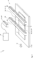
- the image data processor 1 is for the calculation of photometric stereo images 6 and a color image 8 of a with a predetermined relative speed 10 relative to a monochromatic image sensor arrangement 12 (see 2 and 3 ) moving object 14 with a predetermined sensor geometry is provided.
- the image data processor 1 is designed to calculate the photometric stereo images 6 and the color image 8 from at least four image data records 18 in an image calculation unit 16 . This is explained in more detail below.
- the image data records 18 can be read out, for example, directly from monochromatic pixels 20 of the image sensor arrangement 12 after they have been recorded there in succession, as will be explained further below.
- the image data sets 18 can also be stored on a storage medium 22 and read out from it.
- the image data processor 1 can have a corresponding readout unit 24 and a readout interface 26 .
- the image data sets 18 contain monochromatic gray values that represent brightness values 28 of different locations of a region of the object 14 . At least three of the image datasets 18 represent brightness values 28 of the object 14 illuminated in different wavelength ranges 30. Such image datasets 18 are in 1 marked as an example image data set group 32a. At least two of the image datasets 18 represent brightness values 28 of the object 14 illuminated from different illumination directions 34. Such image datasets 18 are in 1 marked as an example image data set group 32b.
- each image data set 18 contains brightness values 28 measured by the image sensor arrangement 12 at different points of the object 14 under illumination in a predetermined wavelength range 30 from a predetermined illumination direction 34, with at least three of the image data sets 18 differing in the wavelength ranges 30 represented therein (ie image data set group 32a) and wherein at least two of the image data sets 18 differ in the illumination directions 34 represented therein (ie image data set group 32b).
- the same image data sets 18 can belong to the image data set group 32a and 32b at the same time.
- the different wavelength ranges 30 can be, for example, the wavelength ranges of red light 36, green light 38 and blue light 40.
- the wavelength ranges 30 used in the illumination can cover an RGB color space and the color image 8 to be calculated can be an RGB color image 42 .
- UV radiation and/or IR radiation can also be used for the illumination.
- the color image 8 to be calculated can then accordingly be a multispectral image in false color representation, in particular a multispectral image or a hyperspectral image.
- the different illumination directions 34 can result from a unidirectional illumination constellation 44 , a bidirectional illumination constellation 46 or a multidirectional diffuse illumination constellation 48 .
- the unidirectional or bidirectional lighting constellations 44, 46 are mainly used to record the brightness values 28 for the photometric stereo image 6.
- an inclination image, a texture image, a curvature image, a Gradient image and / or a height image are calculated as a photometric stereo image 6.
- the multi-sided, diffuse lighting constellation 48 provides uniform lighting conditions for recording the brightness values 28 for the color image 8.
- the image data processor 1, in particular the readout unit 24, can be configured to assign the associated wavelength range 30 and the associated illumination direction 34 to each brightness value 28.
- the presentation of the image data sets 18 in 1 the brightness values 28 are assigned to the individual pixels 20 of the image sensor arrangement 12 from which they were recorded and together with the entire object 14, the different wavelength ranges 30 and the different illumination directions 34 are shown.
- the lighting constellation 44, 46, 48 that is present in each case is indicated by arrows in the top views 50, with different arrow directions representing different illumination directions 34, while different arrow lines (e.g Dot-dash, solid line, thick line) the different wavelength ranges 30 reproduce.
- the brightness values 28 of the image data sets 18 can be measured by the image sensor arrangement 12 using an electronic shutter.
- the image sensor arrangement with which the image data sets 18 are recorded has four pixel rows 52a, 52b, 52c, 52d.
- the sensor geometry already mentioned above is mainly defined by the mutual spatial distance 54 of the pixel rows 52a, 52b, 52c, 52d (i.e. row distance 124).
- Image data processor 1 is also configured to use spatial distance 54 and speed values 56 representing relative speed 10 from image datasets 18 with different wavelength ranges 30, in particular from the respective image dataset groups 32a, to identify brightness values 28 of individual pixels 20 at the same point in the object region and as to summarize a multicolored pixel tuple 58 (see thought bubble 202 in 1 ).
- the image data processor 1 is designed to use the spatial distance 54 and the speed values 56 from the image data sets 18 with different illumination directions 34, in particular from the respective image data set groups 32b, to identify brightness values of individual pixels 20 at the same point in the object region and to combine them as a multidirectional pixel tuple 60 ( see thought bubble 203 in 1 ).
- the image calculation unit 16 can have a pixel tuple identification module 62 with a block 64 for identifying and combining multicolored pixel tuples 58 and a block 66 for identifying and combining multidirectional pixel tuples 60 .
- Each multicolored pixel tuple 58 is a tuple of length n and contains the brightness values 28 from the image data sets 18 with different wavelength ranges 30 as elements, which were measured by pixels of the image sensor arrangement 12 at one and the same point in the object area, the length n being the number of different Wavelength ranges 30 corresponds.
- each multidirectional pixel tuple 60 is a tuple of length m and contains the brightness values 28 from as elements the image data sets 18 with different illumination directions 34, which were measured by pixels of the image sensor arrangement 12 at one and the same point in the object area, the length m corresponding to the number of different illumination directions 34.
- the image data records 18 are preferably recorded in such a way that for each multicolored pixel tuple 58 there is also a multidirectional pixel tuple 60 which images the same point in the object region, and vice versa. This is explained in more detail below in connection with the device 2 according to the invention and enables the generation of pixel synchronicity between the color components of the color image 8 and the photometric stereo image 6.
- the brightness values 28 of each multicolored pixel tuple 58 can, for example, be unambiguously assignable to a wavelength range 30 as a result of their arrangement within the pixel tuple 58 .
- the brightness values 28 of each multidirectional pixel tuple 60 can be uniquely assigned to an illumination direction 34 by their arrangement within the pixel tuple 60 . this is in 1 indicated purely by way of example for pixel tuples 58, 60 with three/two elements 70 (see thought bubbles 202, 203).
- the multicolored pixel tuples 58 and the multidirectional pixel tuples 60 can differ in their number of elements 70 .
- the image data processor 1 is further configured to generate a pixel 72 of the color image 8 based on each multicolored pixel tuple 58 and the wavelength ranges 30, in particular the wavelength ranges 30 of the multisided diffuse illumination constellations 48 (see thought bubble 204 in 1 ). Since all brightness values 28, as already described above, are only available as monochromatic gray values, but can be assigned to a wavelength range 30, the pixel 72 of the color image 8 can be reconstructed as follows.
- the brightness value 28 of an element 70 of the multicolored pixel tuple 58 in combination with the associated wavelength range 30 corresponds to the brightness value 28 of a pixel 74 of a color channel of the color image 8, the color channel representing this wavelength range 30.
- the image data processor 1 is designed to generate a pixel 76 of the photometric stereo image 6 based on each multidirectional pixel tuple 60 and the illumination directions 34, in particular the illumination directions 34 of the directed illumination constellations 44, 46 (see thought bubble 205 in 1 ).
- the so-called photometric stereo method which is known to a person skilled in the art from the prior art and is therefore only explained in outline below, is used to generate the image point 76 .
- the brightness value 28 of each element 70 of the multidirectional pixel tuple 60 and the associated direction of illumination 34 are used in accordance with the photometric stereo method in an equation of an equation system for calculating a surface normal at the location of the object area which the pixel tuple 60 depicts.
- the system of equations reflects the qualitative relationship that an object surface facing a directed light source reflects more light and therefore appears brighter to an observer (here: image sensor arrangement 12) than an object surface facing away from this light source.
- Object surfaces that are on the side of the light source have a medium brightness.
- a color value or a gray value 78 can be assigned to the orientation of the surface normal calculated for the pixel tuple 60 via an arbitrarily definable color coding. This color value or gray value 78 then corresponds to the color value or gray value 80 of the pixel 76.
- the entire photometric stereo image 6 results from the totality of the pixels 76 generated in this way (see thought bubble 207 in 1 ).
- the image calculation unit 16 can have a pixel generation module 82 with a block 84 for generating the pixels 72 of the color image 8 and a block 86 for generating the pixels 76 of the photometric stereo image 6. Because of the pixel synchronicity already mentioned, the color image 8 and the photometric stereo image 6 can optionally be combined in the image calculation unit 16 to form a photometric stereo color image.
- the image data processor 1 can have an internal data memory 88 which is designed to store intermediate results of the method steps running in the image data processor 1 or temporarily.
- the Thought Bubbles 201, 202, 203, 204, 205, 206 and 207 off 1 are only intended to represent a symbolic representation of the method steps taking place in the image data processor 1. Their placement in the area of the data store 88 is due to space constraints and is not intended to mean that such a graphic display must take place in the image data processor 1 or in the data store 88.
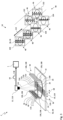
- FIG 2 and 3 12 show schematic representations of exemplary embodiments of the device 2 according to the invention, which has the image sensor arrangement 12 already mentioned above and an illumination arrangement 90 .
- the construction and function of the lighting arrangement 90 are described below with reference to FIG 2 explained, in which the image sensor arrangement 12 is shown only greatly simplified.
- the image sensor array 12 is again discussed with reference to FIG 3 described, in which, for the sake of a better overview, the lighting arrangement 90 is shown in a greatly simplified form.
- the device 2 is used to generate the photometric stereo image 6 and the color image 8.
- the lighting arrangement 90 of the device 2 is used to generate the lighting constellations 44, 46, 48 and the image sensor arrangement 12 of the device 2 is used to record the brightness values 28 for the image data sets 18
- the device 2 can also have a conveying device 92, for example a conveyor belt 94, on which the object 14 can be moved relative to the device 2, in particular relative to the image sensor arrangement 12.
- the device 2, in particular the image sensor arrangement 12 can also be designed to be movable relative to the object 14.
- the illumination arrangement 90 is aligned with an illumination area 96 and configured to emit an illumination sequence 98 into the illumination area 96 in a cyclic manner.
- the illumination sequence 98 has at least four illumination pulses 100 which are preferably repeated periodically, each illumination pulse 100 having a wavelength range 30 and an illumination direction 34 .
- the wavelength range 30 can be continuous, interrupted or formed from individual spectral lines.
- the illumination direction 34 is the spatial direction in which the respective illumination pulse 100 propagates towards the illumination region 96 .
- At least three of the illumination pulses 100 differ in their respective wavelength ranges 30 and at least two of the illumination pulses 100 differ by their respective directions of illumination 34, which is reflected in the image data record groups 32a, 32b already mentioned above.
- the illumination pulses 100 may be emitted individually from the illumination assembly 90 and each create a unidirectional illumination constellation 44 .
- a two-way illumination constellation 46 see FIG 3
- a multi-sided diffuse illumination constellation 48 result. This is explained below.
- the lighting arrangement 90 can e.g. B. configured to emit a first illumination pulse 100a in a first wavelength range 30a from a first illumination direction 34a, a second illumination pulse 100b in a second wavelength range 30b from a second illumination direction 34b and a third illumination pulse 100c in a third wavelength range 30c from a third illumination direction 34c , wherein the wavelength ranges 30a, 30b, 30c are not congruent with each other, and wherein the illumination directions 34a, 34b, 34c are not parallel to each other. However, all illumination directions can intersect in the illumination area 96 .
- each illumination pulse 100a, 100b, 100c is emitted individually and in each case generates precisely one unidirectional illumination constellation 44.
- the illumination pulses 100a, 100b, 100c can be repeated periodically.
- the illumination arrangement 90 can also be configured to emit a fourth illumination pulse 100d in the third wavelength range 30c from the illumination direction 34d, with the illumination directions 34c, 34d not being parallel to one another.
- the illumination arrangement 90 can be configured to deliver exactly one illumination pulse in the first wavelength range from each of the first, second, third and fourth illumination directions, exactly one illumination pulse in the second wavelength range from each of the first, second, third and fourth illumination directions and exactly one illumination pulse in the to emit the third wavelength range from each of the first, second, third and fourth illumination directions.
- This is not shown separately. In that case, correspondingly more pixel lines would have to be made available. Namely exactly the number of wavelengths times the number of directions.
- Two illumination pulses 100 in the same wavelength range 30 can also be emitted at the same time in order to generate a bidirectional illumination constellation 46 .
- the directions of illumination of the two illumination pulses emitted at the same time preferably have a horizontal component 102 directed in the same direction and a horizontal component 104 directed in the opposite direction.
- the remaining illumination pulses in the same wavelength range 30 are then preferably also emitted at the same time. This is in plan views 50 of FIG 3 shown.
- the lighting arrangement 90 can have at least three electromagnetic emitters 106 aligned to the lighting region 96, each of which is designed to emit exactly one of the lighting pulses 100 in exactly one wavelength range 30 and exactly one illumination direction 34, so that the top views 50 of 1 lighting sequence 98 shown at the top left is created.
- the electromagnetic radiators 106 are configured with red light 36, green light 38 and blue light 40, with the red light 36, the green light 38 and the blue light 40 being present in alternation and radiating onto the illumination area 96 from different spatial directions for each electronic radiator 106.
- each electromagnetic emitter 106 can have optics (not shown) directed towards the illumination area.
- the illumination arrangement 90 preferably has at least one combined electromagnetic radiator 106 for each different wavelength range 30 of the illumination pulses 100 and/or for each different illumination direction 34 of the illumination pulses 100 .
- the lighting arrangement 90 as exemplified in 3 shown, have four electromagnetic emitters 106 configured as light strips 108 .
- LEDs 110 of each of the different wavelength ranges 30 can be arranged alternately (eg in the order: RGB-...-RGB). In this case, LEDs of the same wavelength range 30 can be controlled independently of the LEDs of the other wavelength ranges 30 .
- the light strips 108 can be configured to radiate onto the illumination area 96 in four different spatial orientations. This makes it possible to generate the lighting sequences 98 shown in the plan views 50 .
- At least one illumination pulse 100 can form a light sheet 112 or a light disk 114.
- each of the electromagnetic emitters 106 can have optics (not shown) directed towards the illumination area 96 .
- the image sensor arrangement 12 For recording the brightness values 28 already mentioned above, the image sensor arrangement 12 has a recording area 116 which is superimposed on the illumination area 96 . In this case, the image sensor arrangement 12 is designed to measure the brightness values 28 in the recording region 116 during each illumination pulse 100 .
- the image sensor arrangement 12 has at least four pixel rows 52a, 52b, 52c, 52d arranged at a spatial distance 54 from one another.
- the image sensor arrangement 12 can have at least one pixel row for each different illumination constellation 44 , 46 , 48 resulting from the illumination sequence 98 .
- This ensures that for each multicolored pixel tuple 58, a multidirectional pixel tuple 60 can also be recorded, which images the same point in the object area.
- the image sensor arrangement 12 can be used, for example, as a multi-line camera 118 (see 3 ) or a matrix camera 120 that can be read line by line (see 2 ) be configured.
- a combination of several cameras of this type can also form the image sensor arrangement 12 .
- the time interval 122 between two consecutive illumination pulses 98 of the illumination sequence 98 is preferably equal to the time during which the image of the object 14 projected onto the image sensor arrangement 12 advances by a distance due to the relative speed 10 , which corresponds to the spatial distance 54 between two adjacent pixel rows.
- the spatial distance 54 and the relative speed 10 can be predefined and the time distance 122 between two successive illumination pulses 100 can be adapted thereto. For example, this adaptation can take place by activating the lighting arrangement 90 .
- the spatial distance 54 and the time distance 122 can be specified and the relative speed 10 can be adapted thereto.
- the conveyor 92 can be controlled accordingly.
- the time interval 122 and the relative speed 10 can be predetermined and the spatial interval 54 can be adapted thereto.
- the spatial distance 54 can be structurally adjusted on the image sensor arrangement 12 in advance. It is also conceivable for the matrix camera 120 that the line spacing 124 is influenced by which lines of the matrix camera 120 are read out. In order to increase the spatial distance 54, instead of every pixel line, only every second pixel line can be read, for example.
- the number of pixel rows of the image sensor arrangement 12 can optionally also be smaller than the number of different illumination constellations 44 , 46 , 48 resulting from the illumination sequence 98 . this is in 3 shown.
- the image sensor arrangement 12 has four pixel rows 52a, 52b, 52c, 52d, while the illumination arrangement 90 is designed to emit an illumination sequence with six different illumination constellations 46, 48 (see top views 50 in 3 ).
- the time interval 122 between two consecutive illumination pulses 98 must be smaller, at least in the case of two illumination constellations 46, than the time during which the image of the object 14 projected onto the image sensor arrangement 12 changes due to the relative speed 10 by the distance which corresponds to the spatial distance 54 between two adjacent pixel rows. Consequently, the brightness values 28 for these lighting constellations 46 must be recorded "between" the pixel rows. this is in 3 indicated by the staggered top views 50 . If the pixel lines are directly adjacent, the brightness values 28 can be approximated by interpolation or averaging.
- the above-mentioned pixel synchronicity can also be achieved with pixel rows that are not immediately adjacent if the "interposed" illumination constellations 46 are generated at the shortest possible time interval from the previous illumination constellation and the brightness values are measured immediately.
- An imaginary raster projection 126 is shown, which shows the data recorded by the individual pixel rows 52a, 52b, 52c, 52d of the image sensor arrangement 12 Object areas indicates. Spatial distance 54 and pixel width 68 are indicated on grid projection 126 .
- the image sensor arrangement 12 can also have other types of pixel arrays.
- the image data processor 1 is designed to identify the multicolored pixel tuples 58 and the multidirectional pixel tuples 60 using other sensor data 57 representing the sensor geometry.
- the speed values 56 and sensor data 57 are preferably constant. Depending on the application, the speed values 56 and/or sensor data 57 can change over time.
- the image data processor 1 can have an interface 128 for inputting or reading out the speed values 56 .
- the image data processor 1 can be connected to a rotary encoder (not shown) of the conveyor device 92 via the interface 128 (see 2 ) can be connected or receive the speed values 56 from it in real time.
- a further interface 130 for entering or reading out the sensor data 57 can optionally also be provided on the image data processor 1 .
- the device 2 can have the image data processor 1 .
- the device 2 can also be connected to a computer 132 on which a computer program can be executed which includes instructions which cause the computer 132 to carry out the method steps already described for the image data processor 1 .
Landscapes
- Engineering & Computer Science (AREA)
- Multimedia (AREA)
- Signal Processing (AREA)
- Physics & Mathematics (AREA)
- Electromagnetism (AREA)
- Length Measuring Devices By Optical Means (AREA)
- Spectrometry And Color Measurement (AREA)
Applications Claiming Priority (1)
| Application Number | Priority Date | Filing Date | Title |
|---|---|---|---|
| DE102021004071.6A DE102021004071B3 (de) | 2021-08-06 | 2021-08-06 | Vorrichtung und Verfahren zum Erzeugen photometrischer Stereobilder und eines Farbbildes |
Publications (4)
| Publication Number | Publication Date |
|---|---|
| EP4131920A2 true EP4131920A2 (fr) | 2023-02-08 |
| EP4131920A3 EP4131920A3 (fr) | 2023-04-19 |
| EP4131920C0 EP4131920C0 (fr) | 2025-01-15 |
| EP4131920B1 EP4131920B1 (fr) | 2025-01-15 |
Family
ID=83115552
Family Applications (1)
| Application Number | Title | Priority Date | Filing Date |
|---|---|---|---|
| EP22186178.4A Active EP4131920B1 (fr) | 2021-08-06 | 2022-07-21 | Dispositif et procédé de génération d'une image stéréo photométrique et d'une image couleur |
Country Status (4)
| Country | Link |
|---|---|
| US (1) | US12095971B2 (fr) |
| EP (1) | EP4131920B1 (fr) |
| DE (1) | DE102021004071B3 (fr) |
| PL (1) | PL4131920T3 (fr) |
Family Cites Families (5)
| Publication number | Priority date | Publication date | Assignee | Title |
|---|---|---|---|---|
| US20040125205A1 (en) * | 2002-12-05 | 2004-07-01 | Geng Z. Jason | System and a method for high speed three-dimensional imaging |
| JP6857079B2 (ja) * | 2017-05-09 | 2021-04-14 | 株式会社キーエンス | 画像検査装置 |
| JP6864549B2 (ja) * | 2017-05-09 | 2021-04-28 | 株式会社キーエンス | 画像検査装置 |
| EP3460753A1 (fr) | 2017-09-21 | 2019-03-27 | Infaimon, SL | Système stéréo photométrique et procédé d'inspection d'objets à l'aide d'une caméra à une prise et programme informatique |
| JP7222796B2 (ja) | 2019-04-05 | 2023-02-15 | 株式会社キーエンス | 画像検査システム及び画像検査方法 |
-
2021
- 2021-08-06 DE DE102021004071.6A patent/DE102021004071B3/de active Active
-
2022
- 2022-07-21 PL PL22186178.4T patent/PL4131920T3/pl unknown
- 2022-07-21 EP EP22186178.4A patent/EP4131920B1/fr active Active
- 2022-08-04 US US17/880,682 patent/US12095971B2/en active Active
Also Published As
| Publication number | Publication date |
|---|---|
| EP4131920A3 (fr) | 2023-04-19 |
| PL4131920T3 (pl) | 2025-06-09 |
| EP4131920C0 (fr) | 2025-01-15 |
| DE102021004071B3 (de) | 2023-01-19 |
| US20230038127A1 (en) | 2023-02-09 |
| US12095971B2 (en) | 2024-09-17 |
| EP4131920B1 (fr) | 2025-01-15 |
Similar Documents
| Publication | Publication Date | Title |
|---|---|---|
| EP2469224B1 (fr) | Procédé de mesure optique intra-orale d'objets en utilisant un procédé de triangulation | |
| DE102012112322B4 (de) | Verfahren zum optischen Abtasten und Vermessen einer Umgebung | |
| DE102008002730B4 (de) | Verfahren und Vorrichtung zur 3D-Rekonstruktion | |
| DE102011106052B4 (de) | Schattenentfernung in einem durch eine fahrzeugbasierte Kamera erfassten Bild unter Verwendung eines nichtlinearen beleuchtungsinvarianten Kerns | |
| DE202012104890U1 (de) | Vorrichtung zum optischen Abtasten und Vermessen einer Umgebung | |
| EP3278302A1 (fr) | Système de mesure de déplacement d'une machine et procédé de fonctionnement du système de mesure de déplacement | |
| DE102012112321A1 (de) | Vorrichtung zum optischen Abtasten und Vermessen einer Umgebung | |
| DE19963333A1 (de) | Verfahren zur Ermittlung von dreidimensionalen Oberflächenkoordinaten | |
| DE102013111761B4 (de) | Verfahren und Scanner zum berührungslosen Ermitteln der Position und dreidimensionalen Form von Produkten auf einer laufenden Fläche | |
| EP3033588A1 (fr) | Procédé et dispositif pour la mesure sans contact de contours de surfaces | |
| EP1485670A2 (fr) | Procede et dispositif pour determiner les coordonnees absolues d'un objet | |
| DE102008002725A1 (de) | Verfahren und Vorrichtung zur 3D-Rekonstruktion | |
| EP2019961B1 (fr) | Procédé pour la génération d'informations d'images | |
| DE102014104903A1 (de) | Verfahren und Sensor zum Erzeugen und Erfassen von Mustern auf einer Oberfläche | |
| DE102021004071B3 (de) | Vorrichtung und Verfahren zum Erzeugen photometrischer Stereobilder und eines Farbbildes | |
| DE102019133515B3 (de) | Verfahren und Vorrichtung zur Parallaxenbestimmung von Aufnahmen eines Multilinsen-Kamerasystems | |
| DE102023133259B3 (de) | Verfahren zum Erfassen einer ein Phasenobjekt umfassenden Szenerie | |
| DE102021104947A1 (de) | Scanner, damit ausgestattete Ermittlungs-Vorrichtung sowie Verfahren für deren Betrieb | |
| DE102023108676B4 (de) | Vorrichtung und Verfahren zur fotogrammetrischen Erstellung eines 3D-Modells eines Objekts mittels strukturiertem Licht | |
| DE102012013079B4 (de) | Verfahren und Vorrichtung zum berührungslosen Erfassen einer dreidimensionalen Kontur | |
| EP3985608B1 (fr) | Procédé mis en oeuvre par ordinateur permettant de créer des structures de données d'objets à dimensions multiples | |
| DE102013223852A1 (de) | Verfahren zur Erstellung von mindestens zwei Bildern mit einer Kameravorrichtung sowie Kameravorrichtung | |
| DE102013104060B4 (de) | Verfahren und Vorrichtung zur videografischen Verfolgung von schnell bewegten Objekten | |
| DE102019133516B4 (de) | Verfahren und Vorrichtung zur Bestimmung von Wellenlängenabweichungen von Aufnahmen eines Multilinsen-Kamerasystems | |
| DE102017220720B4 (de) | Verfahren und Vorrichtung zum berührungslosen Vermessen dreidimensionaler Oberflächenkonturen |
Legal Events
| Date | Code | Title | Description |
|---|---|---|---|
| PUAI | Public reference made under article 153(3) epc to a published international application that has entered the european phase |
Free format text: ORIGINAL CODE: 0009012 |
|
| STAA | Information on the status of an ep patent application or granted ep patent |
Free format text: STATUS: THE APPLICATION HAS BEEN PUBLISHED |
|
| AK | Designated contracting states |
Kind code of ref document: A2 Designated state(s): AL AT BE BG CH CY CZ DE DK EE ES FI FR GB GR HR HU IE IS IT LI LT LU LV MC MK MT NL NO PL PT RO RS SE SI SK SM TR |
|
| PUAL | Search report despatched |
Free format text: ORIGINAL CODE: 0009013 |
|
| AK | Designated contracting states |
Kind code of ref document: A3 Designated state(s): AL AT BE BG CH CY CZ DE DK EE ES FI FR GB GR HR HU IE IS IT LI LT LU LV MC MK MT NL NO PL PT RO RS SE SI SK SM TR |
|
| STAA | Information on the status of an ep patent application or granted ep patent |
Free format text: STATUS: REQUEST FOR EXAMINATION WAS MADE |
|
| 17P | Request for examination filed |
Effective date: 20230525 |
|
| RBV | Designated contracting states (corrected) |
Designated state(s): AL AT BE BG CH CY CZ DE DK EE ES FI FR GB GR HR HU IE IS IT LI LT LU LV MC MK MT NL NO PL PT RO RS SE SI SK SM TR |
|
| STAA | Information on the status of an ep patent application or granted ep patent |
Free format text: STATUS: EXAMINATION IS IN PROGRESS |
|
| 17Q | First examination report despatched |
Effective date: 20240515 |
|
| REG | Reference to a national code |
Ref country code: DE Ref legal event code: R079 Free format text: PREVIOUS MAIN CLASS: H04N0005225000 Ipc: H04N0023600000 Ref document number: 502022002624 Country of ref document: DE |
|
| GRAP | Despatch of communication of intention to grant a patent |
Free format text: ORIGINAL CODE: EPIDOSNIGR1 |
|
| STAA | Information on the status of an ep patent application or granted ep patent |
Free format text: STATUS: GRANT OF PATENT IS INTENDED |
|
| RIC1 | Information provided on ipc code assigned before grant |
Ipc: H04N 23/56 20230101ALI20241004BHEP Ipc: H04N 23/60 20230101AFI20241004BHEP |
|
| INTG | Intention to grant announced |
Effective date: 20241028 |
|
| GRAS | Grant fee paid |
Free format text: ORIGINAL CODE: EPIDOSNIGR3 |
|
| GRAA | (expected) grant |
Free format text: ORIGINAL CODE: 0009210 |
|
| STAA | Information on the status of an ep patent application or granted ep patent |
Free format text: STATUS: THE PATENT HAS BEEN GRANTED |
|
| AK | Designated contracting states |
Kind code of ref document: B1 Designated state(s): AL AT BE BG CH CY CZ DE DK EE ES FI FR GB GR HR HU IE IS IT LI LT LU LV MC MK MT NL NO PL PT RO RS SE SI SK SM TR |
|
| REG | Reference to a national code |
Ref country code: CH Ref legal event code: EP Ref country code: GB Ref legal event code: FG4D Free format text: NOT ENGLISH |
|
| REG | Reference to a national code |
Ref country code: DE Ref legal event code: R096 Ref document number: 502022002624 Country of ref document: DE |
|
| REG | Reference to a national code |
Ref country code: IE Ref legal event code: FG4D Free format text: LANGUAGE OF EP DOCUMENT: GERMAN |
|
| U01 | Request for unitary effect filed |
Effective date: 20250213 |
|
| U07 | Unitary effect registered |
Designated state(s): AT BE BG DE DK EE FI FR IT LT LU LV MT NL PT RO SE SI Effective date: 20250219 |
|
| PG25 | Lapsed in a contracting state [announced via postgrant information from national office to epo] |
Ref country code: RS Free format text: LAPSE BECAUSE OF FAILURE TO SUBMIT A TRANSLATION OF THE DESCRIPTION OR TO PAY THE FEE WITHIN THE PRESCRIBED TIME-LIMIT Effective date: 20250415 |
|
| PG25 | Lapsed in a contracting state [announced via postgrant information from national office to epo] |
Ref country code: ES Free format text: LAPSE BECAUSE OF FAILURE TO SUBMIT A TRANSLATION OF THE DESCRIPTION OR TO PAY THE FEE WITHIN THE PRESCRIBED TIME-LIMIT Effective date: 20250115 |
|
| PG25 | Lapsed in a contracting state [announced via postgrant information from national office to epo] |
Ref country code: IS Free format text: LAPSE BECAUSE OF FAILURE TO SUBMIT A TRANSLATION OF THE DESCRIPTION OR TO PAY THE FEE WITHIN THE PRESCRIBED TIME-LIMIT Effective date: 20250515 Ref country code: NO Free format text: LAPSE BECAUSE OF FAILURE TO SUBMIT A TRANSLATION OF THE DESCRIPTION OR TO PAY THE FEE WITHIN THE PRESCRIBED TIME-LIMIT Effective date: 20250415 |
|
| PG25 | Lapsed in a contracting state [announced via postgrant information from national office to epo] |
Ref country code: HR Free format text: LAPSE BECAUSE OF FAILURE TO SUBMIT A TRANSLATION OF THE DESCRIPTION OR TO PAY THE FEE WITHIN THE PRESCRIBED TIME-LIMIT Effective date: 20250115 |
|
| PG25 | Lapsed in a contracting state [announced via postgrant information from national office to epo] |
Ref country code: GR Free format text: LAPSE BECAUSE OF FAILURE TO SUBMIT A TRANSLATION OF THE DESCRIPTION OR TO PAY THE FEE WITHIN THE PRESCRIBED TIME-LIMIT Effective date: 20250416 |
|
| U20 | Renewal fee for the european patent with unitary effect paid |
Year of fee payment: 4 Effective date: 20250729 |
|
| PG25 | Lapsed in a contracting state [announced via postgrant information from national office to epo] |
Ref country code: SM Free format text: LAPSE BECAUSE OF FAILURE TO SUBMIT A TRANSLATION OF THE DESCRIPTION OR TO PAY THE FEE WITHIN THE PRESCRIBED TIME-LIMIT Effective date: 20250115 |
|
| PGFP | Annual fee paid to national office [announced via postgrant information from national office to epo] |
Ref country code: PL Payment date: 20250709 Year of fee payment: 4 |
|
| PG25 | Lapsed in a contracting state [announced via postgrant information from national office to epo] |
Ref country code: CZ Free format text: LAPSE BECAUSE OF FAILURE TO SUBMIT A TRANSLATION OF THE DESCRIPTION OR TO PAY THE FEE WITHIN THE PRESCRIBED TIME-LIMIT Effective date: 20250115 |
|
| PG25 | Lapsed in a contracting state [announced via postgrant information from national office to epo] |
Ref country code: SK Free format text: LAPSE BECAUSE OF FAILURE TO SUBMIT A TRANSLATION OF THE DESCRIPTION OR TO PAY THE FEE WITHIN THE PRESCRIBED TIME-LIMIT Effective date: 20250115 |
|
| PLBE | No opposition filed within time limit |
Free format text: ORIGINAL CODE: 0009261 |
|
| STAA | Information on the status of an ep patent application or granted ep patent |
Free format text: STATUS: NO OPPOSITION FILED WITHIN TIME LIMIT |
|
| REG | Reference to a national code |
Ref country code: CH Ref legal event code: L10 Free format text: ST27 STATUS EVENT CODE: U-0-0-L10-L00 (AS PROVIDED BY THE NATIONAL OFFICE) Effective date: 20251126 |
|
| 26N | No opposition filed |
Effective date: 20251016 |
|
| REG | Reference to a national code |
Ref country code: CH Ref legal event code: H13 Free format text: ST27 STATUS EVENT CODE: U-0-0-H10-H13 (AS PROVIDED BY THE NATIONAL OFFICE) Effective date: 20260224 |