EP2887010A1 - Procédé et dispositif de mesure optique en trois dimensions d'objets avec un procédé de mesure topométrique ainsi que programme informatique correspondant - Google Patents
Procédé et dispositif de mesure optique en trois dimensions d'objets avec un procédé de mesure topométrique ainsi que programme informatique correspondant Download PDFInfo
- Publication number
- EP2887010A1 EP2887010A1 EP14195437.0A EP14195437A EP2887010A1 EP 2887010 A1 EP2887010 A1 EP 2887010A1 EP 14195437 A EP14195437 A EP 14195437A EP 2887010 A1 EP2887010 A1 EP 2887010A1
- Authority
- EP
- European Patent Office
- Prior art keywords
- projection
- projection pattern
- image
- pattern
- measurement
- Prior art date
- Legal status (The legal status is an assumption and is not a legal conclusion. Google has not performed a legal analysis and makes no representation as to the accuracy of the status listed.)
- Granted
Links
- 238000005259 measurement Methods 0.000 title claims abstract description 215
- 238000000034 method Methods 0.000 title claims abstract description 71
- 230000003287 optical effect Effects 0.000 title claims abstract description 18
- 238000011156 evaluation Methods 0.000 claims description 38
- 238000004590 computer program Methods 0.000 claims description 8
- 239000004973 liquid crystal related substance Substances 0.000 claims description 6
- 238000012545 processing Methods 0.000 claims description 5
- 230000002123 temporal effect Effects 0.000 claims description 2
- 230000003252 repetitive effect Effects 0.000 claims 1
- 238000004458 analytical method Methods 0.000 description 11
- 238000005286 illumination Methods 0.000 description 10
- 230000005855 radiation Effects 0.000 description 7
- 238000013459 approach Methods 0.000 description 6
- 238000003384 imaging method Methods 0.000 description 6
- 239000000306 component Substances 0.000 description 5
- 230000015572 biosynthetic process Effects 0.000 description 4
- 230000000694 effects Effects 0.000 description 4
- 230000005670 electromagnetic radiation Effects 0.000 description 4
- 230000008569 process Effects 0.000 description 4
- 238000005520 cutting process Methods 0.000 description 3
- 238000001514 detection method Methods 0.000 description 3
- XUIMIQQOPSSXEZ-UHFFFAOYSA-N Silicon Chemical compound [Si] XUIMIQQOPSSXEZ-UHFFFAOYSA-N 0.000 description 2
- 230000003213 activating effect Effects 0.000 description 2
- 230000008901 benefit Effects 0.000 description 2
- 238000004364 calculation method Methods 0.000 description 2
- 230000008859 change Effects 0.000 description 2
- 230000001419 dependent effect Effects 0.000 description 2
- 239000011159 matrix material Substances 0.000 description 2
- 229910052710 silicon Inorganic materials 0.000 description 2
- 239000010703 silicon Substances 0.000 description 2
- 206010038743 Restlessness Diseases 0.000 description 1
- 230000004913 activation Effects 0.000 description 1
- 230000004075 alteration Effects 0.000 description 1
- 230000005540 biological transmission Effects 0.000 description 1
- 238000004422 calculation algorithm Methods 0.000 description 1
- 230000001364 causal effect Effects 0.000 description 1
- 239000008358 core component Substances 0.000 description 1
- 238000013461 design Methods 0.000 description 1
- 230000006866 deterioration Effects 0.000 description 1
- 230000007717 exclusion Effects 0.000 description 1
- 239000011521 glass Substances 0.000 description 1
- 238000004519 manufacturing process Methods 0.000 description 1
- 238000002360 preparation method Methods 0.000 description 1
- 238000010561 standard procedure Methods 0.000 description 1
- 239000000758 substrate Substances 0.000 description 1
- 230000009897 systematic effect Effects 0.000 description 1
- 238000012360 testing method Methods 0.000 description 1
- 238000013519 translation Methods 0.000 description 1
Images


Classifications
-
- G—PHYSICS
- G01—MEASURING; TESTING
- G01B—MEASURING LENGTH, THICKNESS OR SIMILAR LINEAR DIMENSIONS; MEASURING ANGLES; MEASURING AREAS; MEASURING IRREGULARITIES OF SURFACES OR CONTOURS
- G01B11/00—Measuring arrangements characterised by the use of optical techniques
- G01B11/24—Measuring arrangements characterised by the use of optical techniques for measuring contours or curvatures
- G01B11/25—Measuring arrangements characterised by the use of optical techniques for measuring contours or curvatures by projecting a pattern, e.g. one or more lines, moiré fringes on the object
- G01B11/2513—Measuring arrangements characterised by the use of optical techniques for measuring contours or curvatures by projecting a pattern, e.g. one or more lines, moiré fringes on the object with several lines being projected in more than one direction, e.g. grids, patterns
Definitions
- the invention relates to a method for the three-dimensional optical measurement of objects with a topometric measuring method by projection of at least one pattern onto an object with a pattern generator and recording at least one image of the object with the aufproji disposeen pattern with at least one image pickup unit for topometric measurement of the object.
- the invention further relates to a device for the three-dimensional optical measurement of objects with a topometric measuring method, wherein the device comprises a topometric sensor comprising at least one projection unit for illuminating partial areas of an object with optional projection pattern segments of a selectable projection pattern and at least one image acquisition unit, and a Control unit and an evaluation unit for topometric evaluation of the recorded with the image pickup unit images of the object to be measured includes.
- a topometric sensor comprising at least one projection unit for illuminating partial areas of an object with optional projection pattern segments of a selectable projection pattern and at least one image acquisition unit, and a Control unit and an evaluation unit for topometric evaluation of the recorded with the image pickup unit images of the object to be measured includes.
- the three-dimensional optical detection of object surfaces by means of optical triangulation sensors according to the principle of topometry is sufficient known.
- patterns in particular stripe patterns, are projected onto the object to be measured.
- the backscattered pattern is recorded by one or more image acquisition units (usually cameras) and then evaluated by an image evaluation unit.
- the patterns projected by the projection unit can be variously designed. Typical projected patterns are stochastic patterns as well as regular patterns, e.g. B. Dot and Strip Patterns. In particular, stripe patterns have established themselves as common patterns in the context of optical 3D measurement.
- the projection unit comprises three core components. These are a lighting unit, a pattern generator and a projection optics.
- the lighting unit provides electromagnetic radiation. Depending on the design of the lighting unit electromagnetic radiation is generated with characterizing properties. These are in particular the wavelength range in which the light source emits radiation and the power.
- the precise determination of the imaged object point in the respective image recording unit generally requires that the pattern signal backscattered by the object is not significantly superimposed by other signals, in particular further, differently shaped pattern signals.
- additional signals e.g, temporal constancy, intensity, etc.
- the effects range from a deterioration of the signal-to-noise ratio to a systematic falsification of the pattern measurement.
- a particular problem with a three-dimensional optical measuring of objects with a topometric measuring method occurs when the projected pattern is reflected several times on the illuminated object. This depends on the inner and outer orientation of the projection unit, the geometry of the object, the position and orientation of the object to the projection unit, as well as the reflection properties of the object. Depending on the inner and outer orientation of the at least one image recording unit, the directly backscattered pattern signal of the observed object point as well as a multiply reflected other pattern signal, which originally illuminated another object point, can overlap in one image area.
- a method and a device for determining the 3D coordinates of an object which seek to avoid measurement errors due to specular reflection of the pattern on the object.
- a pattern is projected onto the object and the pattern reflected by the object is recorded and evaluated.
- the surface normals of the measured object points and their orientation to the projector are determined.
- the object points are divided into at least two classes.
- a pattern is projected onto the first subregion of the object and the pattern reflected by this subregion is recorded.
- a pattern is projected onto the second subregion of the object and the pattern reflected by this subregion is recorded. Due to the unambiguous assignment of the object points based on the surface normal to each subregion, the subregions do not overlap. Indeed, the location and orientation of the object with respect to the projector and the involved imagers and the surface normals must be known prior to computation of the subregions. For this purpose, the position and orientation of the object as well as its surface normal are either determined by a prior "rough" measurement or derived from a CAD data set. When using a CAD data set, the position and orientation of the object with respect to the sensor must be specified. The subsequent classification of the object points based on the position of their surface normal with respect to the respective projection beam in partial regions is based on the assumption that a specular reflection occurs.
- the invention can be carried out with a topometric sensor which includes one or more imaging units. If more than one image acquisition unit is used, the analysis of the subareas per associated projection pattern segment must be separate with respect to an overlap with one or more other subareas of one or more associated projection pattern segments in each image capture unit. Thus, no sub-areas of images of different image-recording units are explicitly matched with respect to overlaps. To create the projection masks, however, the overlap results per image acquisition unit are considered together. Thus, for example, only two projection pattern segments can be part of a common projection mask if their associated sub-areas, viewed separately in each case, have no overlapping partial areas in each participating image acquisition unit.
- the method has the advantage that no implicit assumptions for the reflection behavior are required and the position and orientation of the object to the topometric sensor need not be known. Therefore, no prior three-dimensional measurement of the object is required. With the method, a falsification of the measurement result can be excluded even if multiple reflections occur.
- the method and the device set up for carrying out this method are based on the consideration that measurement errors occur precisely when different signal components of the pattern projected onto the object and then backscattered at the respective measurement image are superimposed on the image position to be evaluated, with multiple reflections of the pattern for the overlay and the resulting measurement errors are the cause.
- An undisturbed measurement is made possible when, as part of a measurement of a pattern at one or more image positions to be evaluated by selective projection of a portion of the original pattern, the overlays are avoided.
- the information is required, which sample shares are superimposed on the respective image position to be evaluated. Exactly these patterns must not be projected on the same side. This information can be obtained, for example, in that each pattern component, i. H.
- each projection pattern segment is projected individually, wherein in each case one measurement image recorded per participating image capture and subsequently all measurement images are evaluated with respect to reflected pattern portions for each image position.
- the knowledge of whether the respective reflected pattern component from a direct reflection, d. H. a one-time reflection on the object, or an indirect reflection, d. H. a multiple reflection on the object, does not matter.
- the step a) of determining the partial areas in at least one image of the object per participating image acquisition unit can take place, for example, by that the object is illuminated by projection through at least one projection pattern segment. Then, the subareas are detected in the at least one image per participating image acquisition unit, which contain a backscattered from the illuminated object signal of each projected projection pattern segment of the pattern generator. Thereupon, the detected subareas are assigned to an associated projection pattern segment.
- This determination of the subareas can take place sequentially for non-overlapping projection pattern segments in succession.
- the entire projection pattern in a variety of z. B. segmented rectangular projection pattern segments and the object then sequentially sequentially lit exclusively with one projection pattern segment. It is then detected which partial areas are illuminated by a respective projection pattern segment. It can then z.
- an exclusion table it is possible to determine which projection pattern segments can be projected onto an object at the same time, without intersecting illuminated faces of the several projection pattern segments.
- these activated projection pattern segments In projecting projection pattern segments of the pattern generator onto an object, these activated projection pattern segments exclusively illuminate the object without other areas of the surface of a pattern generator being active and emitting electromagnetic radiation in those areas onto the object.
- object is not only the primary in the context of this invention to understand the object to be measured. Rather, this term also encompasses the summation of one or more objects to be measured and the background bodies possibly surrounding them.
- object eg object to be measured primarily and / or background body
- the determination of the sub-areas without taking account of a used for the later topometric measurement special pattern, such as a stripe pattern, but simply by activating a portion of the pattern generator and the associated projector so that the object by activating the segment in sections simply with uniform electromagnetic Radiation is applied.
- a used for the later topometric measurement special pattern such as a stripe pattern
- the defined projection pattern segments are in a kind of hierarchical tree structure with one or more logical levels (n) divided. Multiple adjacent projection pattern segments of i + 1.
- Layer or hierarchy level
- layers together form a higher-level projection pattern segment of the i. Level, d. H. an element of the tree structure of the next higher level.
- d. H. several adjacent elements of this next higher level, d. H. several neighboring higher-order projection pattern segments can in turn form an element of the next higher level in this regard.
- the number of selected levels is basically arbitrary. However, it is limited by the number of projection pattern segments of the pattern generator as well as the number of segments (and subsequently the elements of the respective next higher level), which each form an element of the next higher level. It is important that the intersection (average) of all elements of a layer is always an empty set and that the sum (union) of all elements of a layer always corresponds to the same predefined surface (for example, the whole face or a face) of the pattern generator.
- the quad-tree structure can be used, in which a parent area is subdivided into four similar child areas.
- the projection pattern segments can thus be arranged in multiple levels.
- the preferred embodiment is based on the following. In the event that two or more elements of a hierarchical level do not have shared faces, then the dependent child elements or projection pattern segments of the pattern generator also have no common faces. This fact makes it possible to speed up the method by jointly illuminating the object with elements of a hierarchical level (defined projection pattern segments), whose superordinate elements do not share each other with jointly illuminated partial areas for all image acquisition units involved.
- the first measurements are always the same regardless of the object to be measured, ie independent of the position, orientation, reflection properties etc. of the object performed by determining the faces of the parent tree elements.
- the number and severity of the subsequent measurements are carried out dynamically (on the fly) by analysis of the previous measurements and thus dependent on the properties of the object to be measured.
- the number of measurements thereby saved depends on several factors, such as: Example of the number of tree structure levels, selection criteria for simultaneously to be projected subordinate tree structure elements and / or projection pattern segments and in particular the number of occurring in the parent tree elements multiple reflections (overlapping of faces).
- the analysis of the measurement images of the higher-level tree structure elements or of the defined projection pattern segment takes place in real time.
- real time it is understood that the measurement and analysis in a process is carried out immediately following one another, with the measurement and analysis overlapping in time.
- These evaluation steps can to a large extent be carried out in parallel with other necessary work steps, such as the control of the pattern generator for illuminating the object, the recording of a measurement image per image acquisition unit, the transmission of each measurement image in the evaluation, etc.
- the information necessary to determine the one or more projection masks is usually present within several seconds to a maximum of one minute, depending on the number of measurement images required for this purpose.
- the total time depends, among other things, very strongly on the exposure time per measurement image and the number of measurement images, which in turn depends in particular on the reflection properties and the position and orientation of the object.
- the projection pattern segments preferably have identical sizes.
- the projection pattern segments have different sizes from one another.
- a classification of the determined partial areas in the at least one image into a direct reflection surface, in which the signal of a projection pattern segment is backscattered directly from the object after a single reflection, and in an indirect reflection surface, in which the signal of a Projection pattern segment after multiple reflection on the object is backscattered from the object is performed.
- the indirect reflection surfaces are assigned to the projection pattern segments, which directly illuminate the assigned indirect reflection surface. This classifies each subarea of a measurement image into a direct or indirect reflection surface. Due to their different origins, the surfaces typically have pronounced characteristics. Direct reflection surfaces are usually very compact and often have the same number of corners as the associated tree element or the associated projection pattern segment.
- the boundary lines run in particular when illuminated by small projection pattern segments in a straight line to a good approximation. Furthermore, the contrast between the direct reflection surface and the background is relatively high. In contrast, indirect reflective surfaces have a low compactness. The boundary lines are very restless and often more vertices occur than the associated projection pattern segment has. Furthermore, the contrast between the indirect reflection surface and the background is often relatively small.
- suitable methods of digital image processing which quantify the different characteristic values, a distinction can therefore be made between direct and indirect reflection. This applies both to smaller subordinate projection pattern segments and to larger parent projection pattern segments. It is particularly advantageous if the projection masks are created in such a way that direct reflection surfaces do not overlap each other with indirect reflection surfaces, whereas an overlap of direct reflection surfaces with one another or with indirect reflection surfaces is permissible with one another.
- the classification of the determined partial surfaces based on the geometric shape of the respective shape of the respective partial surface, the contrast of the respective partial surface, the position of the respective partial surface with respect to other partial surfaces and / or based on the Epipolargeometrie the at least one image pickup unit and optionally the Pattern generator takes place. This can be done in a reliable manner computer-controlled with the aid of suitable software.
- Another method for classification is based on the use of neighborhood relationships of the tree structure elements or projection pattern segments.
- the associated direct reflection surfaces of the directly adjacent tree structure elements or projection pattern segments in the participating measurement images are usually located directly adjacent to the direct reflection surface of the outgoing tree structure element or projection pattern segment.
- indirect reflection surfaces are generally spatially separated from adjacent reflection surfaces.
- the measurement images can be classified by several neighboring tree elements or projection pattern segments. In some cases, however, due to shadowing by the object in the pattern projection and / or when taking the measurement image of the object to undercuts.
- neighboring tree structure elements or projection pattern segments in the area of shading can no longer be classified with this approach because these associated direct subregions are generally spatially separated in the measurement image.
- the epipolar geometry can be used particularly advantageously as a distinguishing criterion.
- the inner and outer orientation of the projector is known.
- the epipolar line can be calculated in the respective image acquisition unit.
- their corner points lie exactly on the respective epipolar line of the associated corner point of the projection pattern segment or tree structure element.
- the indirect reflection surfaces are more or less arbitrary with respect to the epipolar lines.
- each vertex of the reflection surface of the measurement image of the second image acquisition unit would lie on the respective associated epipolar line of the vertex of the direct reflection surface of the first image acquisition unit.
- the method can now be further optimized based on the following considerations.
- the overlapping of direct reflection surfaces within a tree structure level or for all exclusive projection pattern segments is theoretically not possible.
- an overlap can occur only due to the system blur, among other things, as a result of the imperfection of the projection optics and the receiving optics. It is harmless for the later impact. Consequently, direct reflection areas may overlap.
- the overlapping of indirect reflection surfaces with each other is also harmless. These image areas should not be evaluated anyway with regard to the projection pattern segments or tree structure elements generating them because they lead to completely incorrect 3D points. To avoid such a grossly incorrect evaluation, the classification result can also be used. In addition, such errors can be avoided by other analyzes (eg epipolar geometry, phase direction, etc.). An overlap of direct and indirect reflection ranges, on the other hand, must be avoided since this leads to measurement errors with a direct effect on the determined associated 3D coordinates. Consequently, the mask generation can be optimized so that only an overlap of direct and indirect reflection ranges is not permitted.
- the combination of the tree-structure approach which significantly reduces the necessary number of measurements to determine the illuminated sub-areas per defined projection pattern segment, with the classification of the sub-areas in direct and indirect reflection surfaces to only the projection pattern segments from each other in the preparation of the projection masks separating, where direct and indirect reflecting surfaces overlap, results in a very powerful and fast process. Both the time for the determination of the projection masks and the measuring time for the complete detection of the region of an object which can be illuminated in the context of a topometric sensor alignment with a minimum number of projection masks can therefore be kept relatively small.
- the measurement image used for the evaluation is performed from the difference of the respective measurement image, which was recorded by an object illuminated with at least one projection pattern segment, and the at least one calibration measurement image of the unlit object.
- the topometric measurement of the object is thus finally carried out by evaluating at least one modified measurement image and not by means of the at least one measurement image recorded directly by the at least one image acquisition unit.
- the constant background radiation is eliminated from the measurement image.
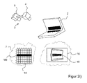
- FIG. 1 shows a sketch of a device 1 for the three-dimensional optical measurement of objects 2 with a topometric sensor 3 to avoid measurement errors due to multiple reflections.
- the topometric sensor 3 comprises a projection unit 4 and at least one image acquisition unit 5.
- the projection unit 4 has a light source 6, a programmable pattern generator 7 with separately controllable individual elements and projection optics 8.
- the topometric sensor 3 further comprises at least one image acquisition unit 5, which is an imaging element 9 and a receiving optics 10 has.
- the topometric sensor 3 is connected to a control unit 11. This is set up so that the topometric sensor 3 can perform measurements in which the pattern generator 7 of the projection unit 4 projects a specific pattern. In particular, patterns can be projected in which only one or more projection pattern segments of the pattern generator 7 illuminate the object 2 to be measured.
- a projection pattern segment is in each case a selected individual element or a contiguous group of adjacent individual elements of the imaging element.
- the control unit 11 is connected to an evaluation unit 12. Furthermore, a display unit 13 is provided which is connected at least to the evaluation unit 12 and the user displays the measurement image 16 or a modified measurement image 17 recorded by the at least one image recording unit 5.
- the evaluation unit 12 analyzes the measurement images recorded by the at least one image recording unit 5 in order to determine the partial surfaces which have arisen by direct or indirect reflection of the pattern, wherein only one or more projection pattern segments of the pattern generator 7 illuminate the object 2 to be measured.
- the measurement images 16 analyzed by the evaluation unit 12 can optionally be modified measurement images 17, in which the measurement images recorded by the image acquisition unit 5 are modified by the influence of the background illumination.
- the evaluation unit 12 is set up to generate at least one projection mask after evaluation of all (possibly modified) measurement images.
- the evaluation unit 12 is preferably suitable for this purpose to carry out the necessary data processing steps with a computer program.
- FIGS. 2a) to 2i illustrate the first embodiment of the method for the three-dimensional optical measurement of objects with the device FIG. 1 using a schematic example.
- FIG. 2a shows a recording configuration for a measurement alignment of the topometric sensor 3 on the object 2.
- the object 2 is to be measured by the topometric sensor 3, which includes a projection unit 4 and an image pickup unit 5, so that no measurement errors due to multiple reflections occur.
- the projection unit 4 contains for this purpose a programmable pattern generator 7 with separately controllable individual elements.
- a programmable pattern generator 7 may include, for example, a digital micromirror device DMD, a liquid crystal display LCD or a liquid crystal on a silicon substrate LCoS.
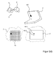
- FIG. 2b omits a sketch of the measurement setup FIG. 2a ) with a definition of the projection pattern segments 14 of the programmable pattern generator 7 and the projection of the projection pattern segments 14 on the object 2 recognize.
- FIG. 2b the outlines of the defined projection pattern segments 14 are projected onto the object 2.
- FIG. 2b bottom left, the two-dimensional representation of the pattern generator 7 with the 64 defined projection pattern segments 14.
- Each segment is uniquely identified by a row and column numbering (eg A1, B1, ... H8).
- FIG. 2 b) at the bottom right shows the associated measurement image 16, which is recorded with the imaging element 9 of the image acquisition unit 5 of this configuration. Again, the recorded segment boundaries of the projection pattern segments 14 are shown on the object 2 in the measurement image 16 for better understanding.
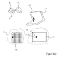
- a measurement image 16 is now respectively recorded by the image acquisition unit 5, in which the respectively associated projection pattern segment 14 of the programmable pattern generator 7 illuminates the object 2 exclusively.
- this process of illuminating the object is sequentially outlined sequentially by the individual projection pattern segments (14) for the segments A1, A3, A4 and A5.
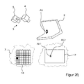
- a calibration measurement image of the object 2 is taken by the image recording unit 5, in which the object 2 is not illuminated by the projection unit 4.
- the calibration measurement image thus contains the information about the influence of a constant background illumination, which also occurs in the later measurements with illumination by selected projection pattern segments 14.
- This calibration measurement image is used to calculate a modified measurement image 17 used for the later evaluation by subtracting from each measurement image 16 for a particular projection pattern segment 14 the calibration measurement image without illumination by the projection unit 4.
- the influence of the backlight (ignoring brightness change and noise) is eliminated mathematically.
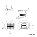
- the modified measuring images 17 of the projection pattern segments A1, A3, A4 and A5, which are each formed by subtraction, ie by subtraction, are shown.
- the reflected partial surfaces 15 are then determined in all modified measuring images 17.
- the detection of these partial surfaces 15 may, for. B. by the application of a gray value threshold. All pixels of the (possibly modified) measurement image 16 (17) above a threshold defined a priori are recognized as partial areas.
- the respective partial surface 15 is a direct or indirect reflection surface.
- all possible combinations of two (possibly modified) measurement images are analyzed by the evaluation unit 12 by suitable programming. For each combination, it is checked whether the respective sub-areas 15 overlap in the identical image areas. If there is an overlap, the two associated projection pattern segments 14 must not illuminate the object 2 at the same time, since then the overlapping of the projected partial patterns of the two projection pattern segments 14 in the image acquisition unit 5 can occur. If the two (possibly modified) measurement images do not include any common subareas 15, then the two associated projection pattern segments 14 can jointly illuminate the object 2, since no superimposition of the subpatterns takes place in the image acquisition unit 5.
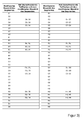
- FIG. 2 are the results of the overlap analysis of the (possibly modified) measurement images in FIG. 3 listed.
- each projection pattern segment A1 to H8 it is listed whether overlapping partial surfaces 15 with the (optionally modified) measurement image of other projection pattern segments occur during the projection with this projection pattern segment A1 to H8.
- So z. B. for the projection pattern segment A3 found that its sub-areas also superimpose the projection pattern segments A4 and A5 associated sub-surfaces 15 in the recorded (possibly modified) measurement image.
- the partial surfaces 15 contained in the (possibly modified) measurement image do not overlap with partial surfaces 15 of another (modified) measurement image. So you can easily share illuminate the object 2, since it does not come in the image pickup unit 5 to a superposition of the pattern signals.
- the evaluation unit is set up by suitable programming in order to record in the first projection mask all the projection pattern segments 14 whose (modified) measurement images have no common sub-areas 15 with other (modified) measurement images. Subsequently, it is advisable to test the other projection pattern segments 14, which may not be projected together with other projection pattern segments 14, with regard to their possible assignment to the first projection mask. If the respective potentially to be added projection pattern segment 14 no overlapping sub-areas 15 with one of the previous projection pattern segments 14 of the respective projection screen in the associated (modified) measurement images 16 (17), this projection pattern segment 14 can be added to this projection mask. For the optional following projection masks can be proceeded very similar.
- the measurement of the projection pattern segments A3, B3, C3, D3, E3, F3, G3 and H3 have no common sub-areas 15 with the projection pattern segments the previous first projection mask M1. They are therefore added to the first projection mask M1.
- projection pattern segments A3, B3, C3, D3, E3, F3, G3 and H3 could have been added instead.
- An alternative useful extension of the projection mask M1 would be z.
- the projection mask M1 would consist of two compact, completely filled partial masks.
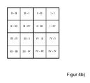
- each quadrant I to IV is subsequently subdivided into four equally sized subquadrants following the same principle.
- the second tree structure level thus comprises 16 elements II to IV-IV, wherein the first quadrant name of the quadrant pairs of the quadrant of the parent tree structure level FIG. 4a ) and the following quadrant designation the respective subquadrants.
- Each element of the second tree structure level is again decomposed analogously into four quadrants. This is in Figure 4c ) recognizable.
- the elements of the third tree structure level are thus identical to the a priori defined projection pattern segments 14 from the embodiment described above.
- the individual elements are thus declared by three consecutive quadrant designations, the first quadrant designation corresponding to the quadrant in the first tree structure plane FIG. 4a ), the middle quadrant designation of the quadrants in the second tree structure level according to FIG. 4b ) and the last quadrant designation according to the sub-sub quadrant in the third tree structure plane Figure 4c ).
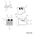
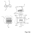
- FIG. 5a exemplifies the device FIG. 1 and 2a ), in the example of each one of the three defined tree structure levels FIGS. 4a) to 4c ) is highlighted.
- This is the element I of the first tree structure plane (characterized by the completely blackened surface), the element II-II of the second tree structure plane (characterized by the blackened triangles) and the element IV-I-IV of the third tree structure plane (indicated by the blackened rhombus).
- a measurement image 16 is respectively taken by the image acquisition unit 5, in which the respectively associated tree structure element of the programmable pattern generator 7 illuminates the object 2 exclusively.
- the reflected partial surfaces 15 are determined in all (possibly modified by subtraction with the Kalibriermesstruck) measurement images.
- all possible combinations of two (modified) measurement images of the first tree structure level are analyzed. Analogously to the described procedure of the first embodiment, it is checked in each combination whether the respective sub-areas 15 overlap in identical image areas. The results of this overlap analysis are in FIG. 6 listed in tabular form.
- the 16 original measurements of the second tree structure level can thus be reduced to eight measurements.
- FIG. 5d it can be seen that for the subordinate projection pattern segments B5, D5, F5 and H5, ie for the projection pattern segments III-II, III-II-I, IV-II and IV-II-I multiple reflections in the area above occur.
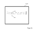
- FIG. 7 is the modified measurement image 17-A3 off Figure 2d ) enlarged.
- the two partial surfaces A3-1 and A3-2 are detected.
- the contour of the partial surfaces 15 is shown. Since the inner and outer orientations of the projection unit 4 and of the image acquisition unit 5 are known, the epipolar lines E1, E2, E3 and E4 of the four vertices of the projection pattern segment A3 can be drawn into the modified measurement image 17-A3.
- the partial area of the object 2 which is illuminated by a projection pattern segment 14 is, to a good approximation, a plane area, provided that the size of the partial area is only sufficiently small.
- a straight line is shown as a straight line.
- the area illuminated on the object 2 by the respectively active projection pattern segment 14 is a quadrangle with, to a good approximation, straight boundary lines.
- the subarea A3-2 of the modified measurement image 17-A3 is produced by a two-fold reflection on the object 2. Its geometric shape is significantly more indefinite. Likewise, the contrast, ie the gray value difference between partial area and background, is significantly weaker. Furthermore, it can be clearly seen that this subarea A3-2 has no relation to the epipolar lines of the vertices of the projection pattern segment A3. In contrast, the partial area A3-1 is encompassed by the epipolar lines. The four corner points of the sub-area A3-1 lie exactly on the associated epipolar line of the associated vertex of the projection pattern segment A3 on the pattern generator 7. On the basis of this analysis, the sub-area A3-1 as direct reflection surface and the sub-area A3-2 as indirect Reflection surface are classified.
- FIG. 8 shows in a common representation the detected partial areas A3-1, A3-2 (hatched highlighted), the partial areas A4-1 and A4-2 (hatched highlighted) for the segments A3 and A4 and the epipolar lines E1, E2, E3 and E4 for the segment A3, as well as the epipolar lines E5, E6, E7 or E8 for the segment A4.
- the subareas A4-1 and A4-2 can also be classified.
- the neighborhood approach can be used here.
- the two indirect sub-areas A3-2 and A4-2 overlap. According to the previous method, therefore, the two associated segments A3 and A4 must not be contained in a common projection mask, since their associated sub-areas overlap in the modified measurement images 17. Since, however, only the direct partial surfaces are to be evaluated with the later measurement with a projection mask, an overlap of these two indirect partial surfaces is irrelevant. Thus, the projection pattern segments A3 and A4 can nevertheless be contained within a projection mask.
- the direct reflection surfaces between two directly adjacent segments also overlap.
- the causes are typically blurring phenomena due to the imperfection of the projection optics 8 or receiving optics 10.
- a blurred projection or image may occur if the object 2 is outside the focal plane of the projection unit 4 or the image recording unit 5. In the previously outlined embodiments, this effect has not been considered.
- various adjacent projection pattern segments 14 should not be part of a common projection mask in the implementation of the method.
- the number of necessary projection masks would thus increase significantly.
- the resulting projection masks would contain a plurality of isolated projection pattern segments 14 (ie projection pattern segments without illumination of the direct neighboring segments).
- the overlap of direct reflection surfaces in the modified measurement image 17 is just as innocuous as the overlap of indirect reflection surfaces. It is only necessary to prevent the overlapping of direct and indirect reflection surfaces.
- projection masks with many isolated elements can be used due to overlapping direct faces due to the blurring overlapping direct faces avoided.
- FIG. 9 shows for the application example FIG. 2 the excluding projection pattern segments 14, in which the respective direct reflection surface of the one projection pattern segment overlap with at least one indirect reflection surface of the other projection pattern segment.
- FIG. 3 With regard to the overlapping of subareas without prior classification, it is shown that various exclusionary projection pattern segments 14 have been omitted within a projection mask in the standard method described at the outset. Since in these cases only indirect sub-areas overlap, which should not be evaluated anyway, they can still be illuminated together in the optimized mask generation.
- the area of the object 2 illuminated by the projection unit 4 can be measured with only two instead of three projection masks without the influence of measurement errors due to multiple reflections.
- the second projection mask M2 remains in the previously described form FIG. 2h ) consist.
Applications Claiming Priority (1)
| Application Number | Priority Date | Filing Date | Title |
|---|---|---|---|
| DE102013114687.2A DE102013114687A1 (de) | 2013-12-20 | 2013-12-20 | Verfahren und Vorrichtung zum dreidimensionalen optischen Vermessen von Objekten mit einem topometrischen Messverfahren sowie Computerprogramm hierzu |
Publications (2)
| Publication Number | Publication Date |
|---|---|
| EP2887010A1 true EP2887010A1 (fr) | 2015-06-24 |
| EP2887010B1 EP2887010B1 (fr) | 2019-09-04 |
Family
ID=52000713
Family Applications (1)
| Application Number | Title | Priority Date | Filing Date |
|---|---|---|---|
| EP14195437.0A Active EP2887010B1 (fr) | 2013-12-20 | 2014-11-28 | Procédé et dispositif de mesure optique en trois dimensions d'objets avec un procédé de mesure topométrique ainsi que programme informatique correspondant |
Country Status (2)
| Country | Link |
|---|---|
| EP (1) | EP2887010B1 (fr) |
| DE (1) | DE102013114687A1 (fr) |
Cited By (1)
| Publication number | Priority date | Publication date | Assignee | Title |
|---|---|---|---|---|
| WO2023011854A1 (fr) * | 2021-08-03 | 2023-02-09 | Sms Group Gmbh | Dispositif de mesure optique d'un filetage à une extrémité d'un tube métallique ou sur un manchon et procédé de mesure |
Families Citing this family (3)
| Publication number | Priority date | Publication date | Assignee | Title |
|---|---|---|---|---|
| DE102018205191A1 (de) | 2018-04-06 | 2019-10-10 | Carl Zeiss Industrielle Messtechnik Gmbh | Verfahren und Anordnung zum Erfassen von Koordinaten einer Objektoberfläche mittels Triangulation |
| DE102018212104A1 (de) | 2018-07-19 | 2020-01-23 | Carl Zeiss Industrielle Messtechnik Gmbh | Verfahren und Anordnung zum optischen Erfassen eines Objekts mittels Lichtmusterprojektion |
| DE102019101313A1 (de) | 2019-01-18 | 2020-07-23 | Gom Gmbh | Messeinrichtung und Verfahren zum dreidimensionalen optischen Vermessen von Messobjekten |
Citations (3)
| Publication number | Priority date | Publication date | Assignee | Title |
|---|---|---|---|---|
| EP0294577A1 (fr) * | 1987-04-30 | 1988-12-14 | Lbp Partnership | Appareil optique de mesure de contours de surfaces |
| WO2004111571A1 (fr) * | 2003-06-12 | 2004-12-23 | UNIVERZA V LJUBLJANI, Fakulteta za strojnistvo | Appareil pour determiner la forme et la taille d'objets tridimensionnels |
| DE102008015499C5 (de) | 2008-03-25 | 2013-01-10 | Steinbichler Optotechnik Gmbh | Verfahren und Vorrichtung zur Bestimmung der 3D-Koordinaten eines Objekts |
-
2013
- 2013-12-20 DE DE102013114687.2A patent/DE102013114687A1/de not_active Withdrawn
-
2014
- 2014-11-28 EP EP14195437.0A patent/EP2887010B1/fr active Active
Patent Citations (3)
| Publication number | Priority date | Publication date | Assignee | Title |
|---|---|---|---|---|
| EP0294577A1 (fr) * | 1987-04-30 | 1988-12-14 | Lbp Partnership | Appareil optique de mesure de contours de surfaces |
| WO2004111571A1 (fr) * | 2003-06-12 | 2004-12-23 | UNIVERZA V LJUBLJANI, Fakulteta za strojnistvo | Appareil pour determiner la forme et la taille d'objets tridimensionnels |
| DE102008015499C5 (de) | 2008-03-25 | 2013-01-10 | Steinbichler Optotechnik Gmbh | Verfahren und Vorrichtung zur Bestimmung der 3D-Koordinaten eines Objekts |
Cited By (1)
| Publication number | Priority date | Publication date | Assignee | Title |
|---|---|---|---|---|
| WO2023011854A1 (fr) * | 2021-08-03 | 2023-02-09 | Sms Group Gmbh | Dispositif de mesure optique d'un filetage à une extrémité d'un tube métallique ou sur un manchon et procédé de mesure |
Also Published As
| Publication number | Publication date |
|---|---|
| EP2887010B1 (fr) | 2019-09-04 |
| DE102013114687A1 (de) | 2015-06-25 |
Similar Documents
| Publication | Publication Date | Title |
|---|---|---|
| EP2469224B1 (fr) | Procédé de mesure optique intra-orale d'objets en utilisant un procédé de triangulation | |
| EP1784978B1 (fr) | Procede et dispositif pour representer une image numerique sur une surface non triviale d'un point de vue geometrique ou photometrique | |
| EP3033588B1 (fr) | Procédé et dispositif pour la mesure sans contact de contours de surfaces | |
| DE102006055758B4 (de) | Verfahren zur Kalibrierung von Kameras und Projektoren | |
| WO2016156406A1 (fr) | Système de mesure de déplacement d'une machine et procédé de fonctionnement du système de mesure de déplacement | |
| DE102014210099B3 (de) | Verfahren zur bildbasierten Kalibrierung von Mehrkamerasystemen mit einstellbarem Fokus und / oder Zoom | |
| DE102015104732A1 (de) | Informationsverarbeitungsvorrichtung, verfahren zum steuern einer informationsverarbeitungsvorrichtung, greifsystem und speichermedium | |
| EP3775767B1 (fr) | Procédé et système de mesure d'un objet par stéréoscopie | |
| EP2887010B1 (fr) | Procédé et dispositif de mesure optique en trois dimensions d'objets avec un procédé de mesure topométrique ainsi que programme informatique correspondant | |
| EP2589926B1 (fr) | Dispositif et procédé de mesure optique de la forme d'un objet mobile | |
| EP3195264A1 (fr) | Dispositif et procédé de représentation tridimensionnelle d'un objet | |
| DE102014207095A1 (de) | Kantenmessungs-Videowerkzeug mit robustem Kantenunterscheidungs-Spielraum | |
| DE102014113389A1 (de) | Verfahren und Vorrichtung zum Identifizieren von Strukturelementen eines projizierten Strukturmusters in Kamerabildern | |
| EP2819109B1 (fr) | Capteur optoélectronique 3D et procédé de reconnaissance d'objets | |
| DE102016100132A1 (de) | Verfahren und Vorrichtung zum Untersuchen eines Objekts unter Verwendung von maschinellem Sehen | |
| DE102017010683B4 (de) | Verfahren zur automatischen Wiederherstellung eines eingemessenen Zustands eines Projektionssystems | |
| DE102012102580A1 (de) | Verfahren zum Messen eines Objektes sowie Intraoral-Scanner | |
| DE112018001600T5 (de) | System und verfahren zur 3d-profilbestimmung unter verwendung einer modellbasierten peak-auswahl | |
| DE19953063A1 (de) | Verfahren zur dreidimensionalen optischen Vermessung von Objektoberflächen | |
| WO2020136037A2 (fr) | Système et procédé de traitement pour traiter les données mesurées d'un capteur d'images | |
| DE102018105794A1 (de) | Abbildung eines Objektes mittels Schattenwurf | |
| DE102013217347A1 (de) | Benutzeroberfläche zur parametereinstellung für kantenmessungs- videowerkzeuge | |
| DE102011000088A1 (de) | Verfahren zur Ermittlung eines Verfahrweges bei der Messung von Strukturen eines Objekts | |
| DE102020216419A1 (de) | Verfahren zum Bestimmen einer Astigmatismuskorrektur | |
| DE102015010264A1 (de) | Verfahren zur Erstellung einer 3D-Repräsentation und korrespondierende Bildaufnahmevorrichtung |
Legal Events
| Date | Code | Title | Description |
|---|---|---|---|
| PUAI | Public reference made under article 153(3) epc to a published international application that has entered the european phase |
Free format text: ORIGINAL CODE: 0009012 |
|
| 17P | Request for examination filed |
Effective date: 20141128 |
|
| AK | Designated contracting states |
Kind code of ref document: A1 Designated state(s): AL AT BE BG CH CY CZ DE DK EE ES FI FR GB GR HR HU IE IS IT LI LT LU LV MC MK MT NL NO PL PT RO RS SE SI SK SM TR |
|
| AX | Request for extension of the european patent |
Extension state: BA ME |
|
| R17P | Request for examination filed (corrected) |
Effective date: 20151216 |
|
| RBV | Designated contracting states (corrected) |
Designated state(s): AL AT BE BG CH CY CZ DE DK EE ES FI FR GB GR HR HU IE IS IT LI LT LU LV MC MK MT NL NO PL PT RO RS SE SI SK SM TR |
|
| RAP1 | Party data changed (applicant data changed or rights of an application transferred) |
Owner name: GOM GMBH |
|
| GRAP | Despatch of communication of intention to grant a patent |
Free format text: ORIGINAL CODE: EPIDOSNIGR1 |
|
| STAA | Information on the status of an ep patent application or granted ep patent |
Free format text: STATUS: GRANT OF PATENT IS INTENDED |
|
| INTG | Intention to grant announced |
Effective date: 20181211 |
|
| GRAJ | Information related to disapproval of communication of intention to grant by the applicant or resumption of examination proceedings by the epo deleted |
Free format text: ORIGINAL CODE: EPIDOSDIGR1 |
|
| STAA | Information on the status of an ep patent application or granted ep patent |
Free format text: STATUS: REQUEST FOR EXAMINATION WAS MADE |
|
| INTC | Intention to grant announced (deleted) | ||
| GRAS | Grant fee paid |
Free format text: ORIGINAL CODE: EPIDOSNIGR3 |
|
| STAA | Information on the status of an ep patent application or granted ep patent |
Free format text: STATUS: GRANT OF PATENT IS INTENDED |
|
| GRAP | Despatch of communication of intention to grant a patent |
Free format text: ORIGINAL CODE: EPIDOSNIGR1 |
|
| INTG | Intention to grant announced |
Effective date: 20190531 |
|
| GRAA | (expected) grant |
Free format text: ORIGINAL CODE: 0009210 |
|
| STAA | Information on the status of an ep patent application or granted ep patent |
Free format text: STATUS: THE PATENT HAS BEEN GRANTED |
|
| AK | Designated contracting states |
Kind code of ref document: B1 Designated state(s): AL AT BE BG CH CY CZ DE DK EE ES FI FR GB GR HR HU IE IS IT LI LT LU LV MC MK MT NL NO PL PT RO RS SE SI SK SM TR |
|
| REG | Reference to a national code |
Ref country code: GB Ref legal event code: FG4D Free format text: NOT ENGLISH |
|
| REG | Reference to a national code |
Ref country code: CH Ref legal event code: EP |
|
| REG | Reference to a national code |
Ref country code: AT Ref legal event code: REF Ref document number: 1175987 Country of ref document: AT Kind code of ref document: T Effective date: 20190915 |
|
| REG | Reference to a national code |
Ref country code: DE Ref legal event code: R096 Ref document number: 502014012556 Country of ref document: DE |
|
| REG | Reference to a national code |
Ref country code: IE Ref legal event code: FG4D Free format text: LANGUAGE OF EP DOCUMENT: GERMAN |
|
| REG | Reference to a national code |
Ref country code: NL Ref legal event code: MP Effective date: 20190904 |
|
| REG | Reference to a national code |
Ref country code: LT Ref legal event code: MG4D |
|
| PG25 | Lapsed in a contracting state [announced via postgrant information from national office to epo] |
Ref country code: LT Free format text: LAPSE BECAUSE OF FAILURE TO SUBMIT A TRANSLATION OF THE DESCRIPTION OR TO PAY THE FEE WITHIN THE PRESCRIBED TIME-LIMIT Effective date: 20190904 Ref country code: SE Free format text: LAPSE BECAUSE OF FAILURE TO SUBMIT A TRANSLATION OF THE DESCRIPTION OR TO PAY THE FEE WITHIN THE PRESCRIBED TIME-LIMIT Effective date: 20190904 Ref country code: NO Free format text: LAPSE BECAUSE OF FAILURE TO SUBMIT A TRANSLATION OF THE DESCRIPTION OR TO PAY THE FEE WITHIN THE PRESCRIBED TIME-LIMIT Effective date: 20191204 Ref country code: BG Free format text: LAPSE BECAUSE OF FAILURE TO SUBMIT A TRANSLATION OF THE DESCRIPTION OR TO PAY THE FEE WITHIN THE PRESCRIBED TIME-LIMIT Effective date: 20191204 Ref country code: HR Free format text: LAPSE BECAUSE OF FAILURE TO SUBMIT A TRANSLATION OF THE DESCRIPTION OR TO PAY THE FEE WITHIN THE PRESCRIBED TIME-LIMIT Effective date: 20190904 Ref country code: FI Free format text: LAPSE BECAUSE OF FAILURE TO SUBMIT A TRANSLATION OF THE DESCRIPTION OR TO PAY THE FEE WITHIN THE PRESCRIBED TIME-LIMIT Effective date: 20190904 |
|
| PG25 | Lapsed in a contracting state [announced via postgrant information from national office to epo] |
Ref country code: LV Free format text: LAPSE BECAUSE OF FAILURE TO SUBMIT A TRANSLATION OF THE DESCRIPTION OR TO PAY THE FEE WITHIN THE PRESCRIBED TIME-LIMIT Effective date: 20190904 Ref country code: ES Free format text: LAPSE BECAUSE OF FAILURE TO SUBMIT A TRANSLATION OF THE DESCRIPTION OR TO PAY THE FEE WITHIN THE PRESCRIBED TIME-LIMIT Effective date: 20190904 Ref country code: RS Free format text: LAPSE BECAUSE OF FAILURE TO SUBMIT A TRANSLATION OF THE DESCRIPTION OR TO PAY THE FEE WITHIN THE PRESCRIBED TIME-LIMIT Effective date: 20190904 Ref country code: GR Free format text: LAPSE BECAUSE OF FAILURE TO SUBMIT A TRANSLATION OF THE DESCRIPTION OR TO PAY THE FEE WITHIN THE PRESCRIBED TIME-LIMIT Effective date: 20191205 Ref country code: AL Free format text: LAPSE BECAUSE OF FAILURE TO SUBMIT A TRANSLATION OF THE DESCRIPTION OR TO PAY THE FEE WITHIN THE PRESCRIBED TIME-LIMIT Effective date: 20190904 |
|
| PG25 | Lapsed in a contracting state [announced via postgrant information from national office to epo] |
Ref country code: RO Free format text: LAPSE BECAUSE OF FAILURE TO SUBMIT A TRANSLATION OF THE DESCRIPTION OR TO PAY THE FEE WITHIN THE PRESCRIBED TIME-LIMIT Effective date: 20190904 Ref country code: IT Free format text: LAPSE BECAUSE OF FAILURE TO SUBMIT A TRANSLATION OF THE DESCRIPTION OR TO PAY THE FEE WITHIN THE PRESCRIBED TIME-LIMIT Effective date: 20190904 Ref country code: EE Free format text: LAPSE BECAUSE OF FAILURE TO SUBMIT A TRANSLATION OF THE DESCRIPTION OR TO PAY THE FEE WITHIN THE PRESCRIBED TIME-LIMIT Effective date: 20190904 Ref country code: NL Free format text: LAPSE BECAUSE OF FAILURE TO SUBMIT A TRANSLATION OF THE DESCRIPTION OR TO PAY THE FEE WITHIN THE PRESCRIBED TIME-LIMIT Effective date: 20190904 Ref country code: PL Free format text: LAPSE BECAUSE OF FAILURE TO SUBMIT A TRANSLATION OF THE DESCRIPTION OR TO PAY THE FEE WITHIN THE PRESCRIBED TIME-LIMIT Effective date: 20190904 Ref country code: PT Free format text: LAPSE BECAUSE OF FAILURE TO SUBMIT A TRANSLATION OF THE DESCRIPTION OR TO PAY THE FEE WITHIN THE PRESCRIBED TIME-LIMIT Effective date: 20200106 |
|
| PG25 | Lapsed in a contracting state [announced via postgrant information from national office to epo] |
Ref country code: CZ Free format text: LAPSE BECAUSE OF FAILURE TO SUBMIT A TRANSLATION OF THE DESCRIPTION OR TO PAY THE FEE WITHIN THE PRESCRIBED TIME-LIMIT Effective date: 20190904 Ref country code: SK Free format text: LAPSE BECAUSE OF FAILURE TO SUBMIT A TRANSLATION OF THE DESCRIPTION OR TO PAY THE FEE WITHIN THE PRESCRIBED TIME-LIMIT Effective date: 20190904 Ref country code: IS Free format text: LAPSE BECAUSE OF FAILURE TO SUBMIT A TRANSLATION OF THE DESCRIPTION OR TO PAY THE FEE WITHIN THE PRESCRIBED TIME-LIMIT Effective date: 20200224 Ref country code: SM Free format text: LAPSE BECAUSE OF FAILURE TO SUBMIT A TRANSLATION OF THE DESCRIPTION OR TO PAY THE FEE WITHIN THE PRESCRIBED TIME-LIMIT Effective date: 20190904 |
|
| REG | Reference to a national code |
Ref country code: DE Ref legal event code: R097 Ref document number: 502014012556 Country of ref document: DE |
|
| REG | Reference to a national code |
Ref country code: CH Ref legal event code: PL |
|
| PLBE | No opposition filed within time limit |
Free format text: ORIGINAL CODE: 0009261 |
|
| STAA | Information on the status of an ep patent application or granted ep patent |
Free format text: STATUS: NO OPPOSITION FILED WITHIN TIME LIMIT |
|
| PG2D | Information on lapse in contracting state deleted |
Ref country code: IS |
|
| PG25 | Lapsed in a contracting state [announced via postgrant information from national office to epo] |
Ref country code: MC Free format text: LAPSE BECAUSE OF FAILURE TO SUBMIT A TRANSLATION OF THE DESCRIPTION OR TO PAY THE FEE WITHIN THE PRESCRIBED TIME-LIMIT Effective date: 20190904 Ref country code: CH Free format text: LAPSE BECAUSE OF NON-PAYMENT OF DUE FEES Effective date: 20191130 Ref country code: LU Free format text: LAPSE BECAUSE OF NON-PAYMENT OF DUE FEES Effective date: 20191128 Ref country code: DK Free format text: LAPSE BECAUSE OF FAILURE TO SUBMIT A TRANSLATION OF THE DESCRIPTION OR TO PAY THE FEE WITHIN THE PRESCRIBED TIME-LIMIT Effective date: 20190904 Ref country code: LI Free format text: LAPSE BECAUSE OF NON-PAYMENT OF DUE FEES Effective date: 20191130 Ref country code: IS Free format text: LAPSE BECAUSE OF FAILURE TO SUBMIT A TRANSLATION OF THE DESCRIPTION OR TO PAY THE FEE WITHIN THE PRESCRIBED TIME-LIMIT Effective date: 20200105 |
|
| 26N | No opposition filed |
Effective date: 20200605 |
|
| REG | Reference to a national code |
Ref country code: BE Ref legal event code: MM Effective date: 20191130 |
|
| PG25 | Lapsed in a contracting state [announced via postgrant information from national office to epo] |
Ref country code: SI Free format text: LAPSE BECAUSE OF FAILURE TO SUBMIT A TRANSLATION OF THE DESCRIPTION OR TO PAY THE FEE WITHIN THE PRESCRIBED TIME-LIMIT Effective date: 20190904 |
|
| PG25 | Lapsed in a contracting state [announced via postgrant information from national office to epo] |
Ref country code: IE Free format text: LAPSE BECAUSE OF NON-PAYMENT OF DUE FEES Effective date: 20191128 |
|
| PG25 | Lapsed in a contracting state [announced via postgrant information from national office to epo] |
Ref country code: BE Free format text: LAPSE BECAUSE OF NON-PAYMENT OF DUE FEES Effective date: 20191130 |
|
| REG | Reference to a national code |
Ref country code: AT Ref legal event code: MM01 Ref document number: 1175987 Country of ref document: AT Kind code of ref document: T Effective date: 20191128 |
|
| PG25 | Lapsed in a contracting state [announced via postgrant information from national office to epo] |
Ref country code: AT Free format text: LAPSE BECAUSE OF NON-PAYMENT OF DUE FEES Effective date: 20191128 |
|
| PG25 | Lapsed in a contracting state [announced via postgrant information from national office to epo] |
Ref country code: CY Free format text: LAPSE BECAUSE OF FAILURE TO SUBMIT A TRANSLATION OF THE DESCRIPTION OR TO PAY THE FEE WITHIN THE PRESCRIBED TIME-LIMIT Effective date: 20190904 |
|
| PG25 | Lapsed in a contracting state [announced via postgrant information from national office to epo] |
Ref country code: MT Free format text: LAPSE BECAUSE OF FAILURE TO SUBMIT A TRANSLATION OF THE DESCRIPTION OR TO PAY THE FEE WITHIN THE PRESCRIBED TIME-LIMIT Effective date: 20190904 Ref country code: HU Free format text: LAPSE BECAUSE OF FAILURE TO SUBMIT A TRANSLATION OF THE DESCRIPTION OR TO PAY THE FEE WITHIN THE PRESCRIBED TIME-LIMIT; INVALID AB INITIO Effective date: 20141128 |
|
| PG25 | Lapsed in a contracting state [announced via postgrant information from national office to epo] |
Ref country code: TR Free format text: LAPSE BECAUSE OF FAILURE TO SUBMIT A TRANSLATION OF THE DESCRIPTION OR TO PAY THE FEE WITHIN THE PRESCRIBED TIME-LIMIT Effective date: 20190904 |
|
| PG25 | Lapsed in a contracting state [announced via postgrant information from national office to epo] |
Ref country code: MK Free format text: LAPSE BECAUSE OF FAILURE TO SUBMIT A TRANSLATION OF THE DESCRIPTION OR TO PAY THE FEE WITHIN THE PRESCRIBED TIME-LIMIT Effective date: 20190904 |
|
| REG | Reference to a national code |
Ref country code: DE Ref legal event code: R082 Ref document number: 502014012556 Country of ref document: DE Representative=s name: MEISSNER BOLTE PATENTANWAELTE RECHTSANWAELTE P, DE |
|
| P01 | Opt-out of the competence of the unified patent court (upc) registered |
Effective date: 20230516 |
|
| PGFP | Annual fee paid to national office [announced via postgrant information from national office to epo] |
Ref country code: GB Payment date: 20231123 Year of fee payment: 10 |
|
| PGFP | Annual fee paid to national office [announced via postgrant information from national office to epo] |
Ref country code: FR Payment date: 20231123 Year of fee payment: 10 Ref country code: DE Payment date: 20231130 Year of fee payment: 10 |