EP2887010A1 - Method and device for three dimensional optical measurement of objects with a topometric measuring method and computer programme for same - Google Patents
Method and device for three dimensional optical measurement of objects with a topometric measuring method and computer programme for same Download PDFInfo
- Publication number
- EP2887010A1 EP2887010A1 EP14195437.0A EP14195437A EP2887010A1 EP 2887010 A1 EP2887010 A1 EP 2887010A1 EP 14195437 A EP14195437 A EP 14195437A EP 2887010 A1 EP2887010 A1 EP 2887010A1
- Authority
- EP
- European Patent Office
- Prior art keywords
- projection
- projection pattern
- image
- pattern
- measurement
- Prior art date
- Legal status (The legal status is an assumption and is not a legal conclusion. Google has not performed a legal analysis and makes no representation as to the accuracy of the status listed.)
- Granted
Links
- 238000005259 measurement Methods 0.000 title claims abstract description 215
- 238000000034 method Methods 0.000 title claims abstract description 71
- 230000003287 optical effect Effects 0.000 title claims abstract description 18
- 238000011156 evaluation Methods 0.000 claims description 38
- 238000004590 computer program Methods 0.000 claims description 8
- 239000004973 liquid crystal related substance Substances 0.000 claims description 6
- 238000012545 processing Methods 0.000 claims description 5
- 230000002123 temporal effect Effects 0.000 claims description 2
- 230000003252 repetitive effect Effects 0.000 claims 1
- 238000004458 analytical method Methods 0.000 description 11
- 238000005286 illumination Methods 0.000 description 10
- 230000005855 radiation Effects 0.000 description 7
- 238000013459 approach Methods 0.000 description 6
- 238000003384 imaging method Methods 0.000 description 6
- 239000000306 component Substances 0.000 description 5
- 230000015572 biosynthetic process Effects 0.000 description 4
- 230000000694 effects Effects 0.000 description 4
- 230000005670 electromagnetic radiation Effects 0.000 description 4
- 230000008569 process Effects 0.000 description 4
- 238000005520 cutting process Methods 0.000 description 3
- 238000001514 detection method Methods 0.000 description 3
- XUIMIQQOPSSXEZ-UHFFFAOYSA-N Silicon Chemical compound [Si] XUIMIQQOPSSXEZ-UHFFFAOYSA-N 0.000 description 2
- 230000003213 activating effect Effects 0.000 description 2
- 230000008901 benefit Effects 0.000 description 2
- 238000004364 calculation method Methods 0.000 description 2
- 230000008859 change Effects 0.000 description 2
- 230000001419 dependent effect Effects 0.000 description 2
- 239000011159 matrix material Substances 0.000 description 2
- 229910052710 silicon Inorganic materials 0.000 description 2
- 239000010703 silicon Substances 0.000 description 2
- 206010038743 Restlessness Diseases 0.000 description 1
- 230000004913 activation Effects 0.000 description 1
- 230000004075 alteration Effects 0.000 description 1
- 230000005540 biological transmission Effects 0.000 description 1
- 238000004422 calculation algorithm Methods 0.000 description 1
- 230000001364 causal effect Effects 0.000 description 1
- 239000008358 core component Substances 0.000 description 1
- 238000013461 design Methods 0.000 description 1
- 230000006866 deterioration Effects 0.000 description 1
- 230000007717 exclusion Effects 0.000 description 1
- 239000011521 glass Substances 0.000 description 1
- 238000004519 manufacturing process Methods 0.000 description 1
- 238000002360 preparation method Methods 0.000 description 1
- 238000010561 standard procedure Methods 0.000 description 1
- 239000000758 substrate Substances 0.000 description 1
- 230000009897 systematic effect Effects 0.000 description 1
- 238000012360 testing method Methods 0.000 description 1
- 238000013519 translation Methods 0.000 description 1
Images


Classifications
-
- G—PHYSICS
- G01—MEASURING; TESTING
- G01B—MEASURING LENGTH, THICKNESS OR SIMILAR LINEAR DIMENSIONS; MEASURING ANGLES; MEASURING AREAS; MEASURING IRREGULARITIES OF SURFACES OR CONTOURS
- G01B11/00—Measuring arrangements characterised by the use of optical techniques
- G01B11/24—Measuring arrangements characterised by the use of optical techniques for measuring contours or curvatures
- G01B11/25—Measuring arrangements characterised by the use of optical techniques for measuring contours or curvatures by projecting a pattern, e.g. one or more lines, moiré fringes on the object
- G01B11/2513—Measuring arrangements characterised by the use of optical techniques for measuring contours or curvatures by projecting a pattern, e.g. one or more lines, moiré fringes on the object with several lines being projected in more than one direction, e.g. grids, patterns
Definitions
- the invention relates to a method for the three-dimensional optical measurement of objects with a topometric measuring method by projection of at least one pattern onto an object with a pattern generator and recording at least one image of the object with the aufproji disposeen pattern with at least one image pickup unit for topometric measurement of the object.
- the invention further relates to a device for the three-dimensional optical measurement of objects with a topometric measuring method, wherein the device comprises a topometric sensor comprising at least one projection unit for illuminating partial areas of an object with optional projection pattern segments of a selectable projection pattern and at least one image acquisition unit, and a Control unit and an evaluation unit for topometric evaluation of the recorded with the image pickup unit images of the object to be measured includes.
- a topometric sensor comprising at least one projection unit for illuminating partial areas of an object with optional projection pattern segments of a selectable projection pattern and at least one image acquisition unit, and a Control unit and an evaluation unit for topometric evaluation of the recorded with the image pickup unit images of the object to be measured includes.
- the three-dimensional optical detection of object surfaces by means of optical triangulation sensors according to the principle of topometry is sufficient known.
- patterns in particular stripe patterns, are projected onto the object to be measured.
- the backscattered pattern is recorded by one or more image acquisition units (usually cameras) and then evaluated by an image evaluation unit.
- the patterns projected by the projection unit can be variously designed. Typical projected patterns are stochastic patterns as well as regular patterns, e.g. B. Dot and Strip Patterns. In particular, stripe patterns have established themselves as common patterns in the context of optical 3D measurement.
- the projection unit comprises three core components. These are a lighting unit, a pattern generator and a projection optics.
- the lighting unit provides electromagnetic radiation. Depending on the design of the lighting unit electromagnetic radiation is generated with characterizing properties. These are in particular the wavelength range in which the light source emits radiation and the power.
- the precise determination of the imaged object point in the respective image recording unit generally requires that the pattern signal backscattered by the object is not significantly superimposed by other signals, in particular further, differently shaped pattern signals.
- additional signals e.g, temporal constancy, intensity, etc.
- the effects range from a deterioration of the signal-to-noise ratio to a systematic falsification of the pattern measurement.
- a particular problem with a three-dimensional optical measuring of objects with a topometric measuring method occurs when the projected pattern is reflected several times on the illuminated object. This depends on the inner and outer orientation of the projection unit, the geometry of the object, the position and orientation of the object to the projection unit, as well as the reflection properties of the object. Depending on the inner and outer orientation of the at least one image recording unit, the directly backscattered pattern signal of the observed object point as well as a multiply reflected other pattern signal, which originally illuminated another object point, can overlap in one image area.
- a method and a device for determining the 3D coordinates of an object which seek to avoid measurement errors due to specular reflection of the pattern on the object.
- a pattern is projected onto the object and the pattern reflected by the object is recorded and evaluated.
- the surface normals of the measured object points and their orientation to the projector are determined.
- the object points are divided into at least two classes.
- a pattern is projected onto the first subregion of the object and the pattern reflected by this subregion is recorded.
- a pattern is projected onto the second subregion of the object and the pattern reflected by this subregion is recorded. Due to the unambiguous assignment of the object points based on the surface normal to each subregion, the subregions do not overlap. Indeed, the location and orientation of the object with respect to the projector and the involved imagers and the surface normals must be known prior to computation of the subregions. For this purpose, the position and orientation of the object as well as its surface normal are either determined by a prior "rough" measurement or derived from a CAD data set. When using a CAD data set, the position and orientation of the object with respect to the sensor must be specified. The subsequent classification of the object points based on the position of their surface normal with respect to the respective projection beam in partial regions is based on the assumption that a specular reflection occurs.
- the invention can be carried out with a topometric sensor which includes one or more imaging units. If more than one image acquisition unit is used, the analysis of the subareas per associated projection pattern segment must be separate with respect to an overlap with one or more other subareas of one or more associated projection pattern segments in each image capture unit. Thus, no sub-areas of images of different image-recording units are explicitly matched with respect to overlaps. To create the projection masks, however, the overlap results per image acquisition unit are considered together. Thus, for example, only two projection pattern segments can be part of a common projection mask if their associated sub-areas, viewed separately in each case, have no overlapping partial areas in each participating image acquisition unit.
- the method has the advantage that no implicit assumptions for the reflection behavior are required and the position and orientation of the object to the topometric sensor need not be known. Therefore, no prior three-dimensional measurement of the object is required. With the method, a falsification of the measurement result can be excluded even if multiple reflections occur.
- the method and the device set up for carrying out this method are based on the consideration that measurement errors occur precisely when different signal components of the pattern projected onto the object and then backscattered at the respective measurement image are superimposed on the image position to be evaluated, with multiple reflections of the pattern for the overlay and the resulting measurement errors are the cause.
- An undisturbed measurement is made possible when, as part of a measurement of a pattern at one or more image positions to be evaluated by selective projection of a portion of the original pattern, the overlays are avoided.
- the information is required, which sample shares are superimposed on the respective image position to be evaluated. Exactly these patterns must not be projected on the same side. This information can be obtained, for example, in that each pattern component, i. H.
- each projection pattern segment is projected individually, wherein in each case one measurement image recorded per participating image capture and subsequently all measurement images are evaluated with respect to reflected pattern portions for each image position.
- the knowledge of whether the respective reflected pattern component from a direct reflection, d. H. a one-time reflection on the object, or an indirect reflection, d. H. a multiple reflection on the object, does not matter.
- the step a) of determining the partial areas in at least one image of the object per participating image acquisition unit can take place, for example, by that the object is illuminated by projection through at least one projection pattern segment. Then, the subareas are detected in the at least one image per participating image acquisition unit, which contain a backscattered from the illuminated object signal of each projected projection pattern segment of the pattern generator. Thereupon, the detected subareas are assigned to an associated projection pattern segment.
- This determination of the subareas can take place sequentially for non-overlapping projection pattern segments in succession.
- the entire projection pattern in a variety of z. B. segmented rectangular projection pattern segments and the object then sequentially sequentially lit exclusively with one projection pattern segment. It is then detected which partial areas are illuminated by a respective projection pattern segment. It can then z.
- an exclusion table it is possible to determine which projection pattern segments can be projected onto an object at the same time, without intersecting illuminated faces of the several projection pattern segments.
- these activated projection pattern segments In projecting projection pattern segments of the pattern generator onto an object, these activated projection pattern segments exclusively illuminate the object without other areas of the surface of a pattern generator being active and emitting electromagnetic radiation in those areas onto the object.
- object is not only the primary in the context of this invention to understand the object to be measured. Rather, this term also encompasses the summation of one or more objects to be measured and the background bodies possibly surrounding them.
- object eg object to be measured primarily and / or background body
- the determination of the sub-areas without taking account of a used for the later topometric measurement special pattern, such as a stripe pattern, but simply by activating a portion of the pattern generator and the associated projector so that the object by activating the segment in sections simply with uniform electromagnetic Radiation is applied.
- a used for the later topometric measurement special pattern such as a stripe pattern
- the defined projection pattern segments are in a kind of hierarchical tree structure with one or more logical levels (n) divided. Multiple adjacent projection pattern segments of i + 1.
- Layer or hierarchy level
- layers together form a higher-level projection pattern segment of the i. Level, d. H. an element of the tree structure of the next higher level.
- d. H. several adjacent elements of this next higher level, d. H. several neighboring higher-order projection pattern segments can in turn form an element of the next higher level in this regard.
- the number of selected levels is basically arbitrary. However, it is limited by the number of projection pattern segments of the pattern generator as well as the number of segments (and subsequently the elements of the respective next higher level), which each form an element of the next higher level. It is important that the intersection (average) of all elements of a layer is always an empty set and that the sum (union) of all elements of a layer always corresponds to the same predefined surface (for example, the whole face or a face) of the pattern generator.
- the quad-tree structure can be used, in which a parent area is subdivided into four similar child areas.
- the projection pattern segments can thus be arranged in multiple levels.
- the preferred embodiment is based on the following. In the event that two or more elements of a hierarchical level do not have shared faces, then the dependent child elements or projection pattern segments of the pattern generator also have no common faces. This fact makes it possible to speed up the method by jointly illuminating the object with elements of a hierarchical level (defined projection pattern segments), whose superordinate elements do not share each other with jointly illuminated partial areas for all image acquisition units involved.
- the first measurements are always the same regardless of the object to be measured, ie independent of the position, orientation, reflection properties etc. of the object performed by determining the faces of the parent tree elements.
- the number and severity of the subsequent measurements are carried out dynamically (on the fly) by analysis of the previous measurements and thus dependent on the properties of the object to be measured.
- the number of measurements thereby saved depends on several factors, such as: Example of the number of tree structure levels, selection criteria for simultaneously to be projected subordinate tree structure elements and / or projection pattern segments and in particular the number of occurring in the parent tree elements multiple reflections (overlapping of faces).
- the analysis of the measurement images of the higher-level tree structure elements or of the defined projection pattern segment takes place in real time.
- real time it is understood that the measurement and analysis in a process is carried out immediately following one another, with the measurement and analysis overlapping in time.
- These evaluation steps can to a large extent be carried out in parallel with other necessary work steps, such as the control of the pattern generator for illuminating the object, the recording of a measurement image per image acquisition unit, the transmission of each measurement image in the evaluation, etc.
- the information necessary to determine the one or more projection masks is usually present within several seconds to a maximum of one minute, depending on the number of measurement images required for this purpose.
- the total time depends, among other things, very strongly on the exposure time per measurement image and the number of measurement images, which in turn depends in particular on the reflection properties and the position and orientation of the object.
- the projection pattern segments preferably have identical sizes.
- the projection pattern segments have different sizes from one another.
- a classification of the determined partial areas in the at least one image into a direct reflection surface, in which the signal of a projection pattern segment is backscattered directly from the object after a single reflection, and in an indirect reflection surface, in which the signal of a Projection pattern segment after multiple reflection on the object is backscattered from the object is performed.
- the indirect reflection surfaces are assigned to the projection pattern segments, which directly illuminate the assigned indirect reflection surface. This classifies each subarea of a measurement image into a direct or indirect reflection surface. Due to their different origins, the surfaces typically have pronounced characteristics. Direct reflection surfaces are usually very compact and often have the same number of corners as the associated tree element or the associated projection pattern segment.
- the boundary lines run in particular when illuminated by small projection pattern segments in a straight line to a good approximation. Furthermore, the contrast between the direct reflection surface and the background is relatively high. In contrast, indirect reflective surfaces have a low compactness. The boundary lines are very restless and often more vertices occur than the associated projection pattern segment has. Furthermore, the contrast between the indirect reflection surface and the background is often relatively small.
- suitable methods of digital image processing which quantify the different characteristic values, a distinction can therefore be made between direct and indirect reflection. This applies both to smaller subordinate projection pattern segments and to larger parent projection pattern segments. It is particularly advantageous if the projection masks are created in such a way that direct reflection surfaces do not overlap each other with indirect reflection surfaces, whereas an overlap of direct reflection surfaces with one another or with indirect reflection surfaces is permissible with one another.
- the classification of the determined partial surfaces based on the geometric shape of the respective shape of the respective partial surface, the contrast of the respective partial surface, the position of the respective partial surface with respect to other partial surfaces and / or based on the Epipolargeometrie the at least one image pickup unit and optionally the Pattern generator takes place. This can be done in a reliable manner computer-controlled with the aid of suitable software.
- Another method for classification is based on the use of neighborhood relationships of the tree structure elements or projection pattern segments.
- the associated direct reflection surfaces of the directly adjacent tree structure elements or projection pattern segments in the participating measurement images are usually located directly adjacent to the direct reflection surface of the outgoing tree structure element or projection pattern segment.
- indirect reflection surfaces are generally spatially separated from adjacent reflection surfaces.
- the measurement images can be classified by several neighboring tree elements or projection pattern segments. In some cases, however, due to shadowing by the object in the pattern projection and / or when taking the measurement image of the object to undercuts.
- neighboring tree structure elements or projection pattern segments in the area of shading can no longer be classified with this approach because these associated direct subregions are generally spatially separated in the measurement image.
- the epipolar geometry can be used particularly advantageously as a distinguishing criterion.
- the inner and outer orientation of the projector is known.
- the epipolar line can be calculated in the respective image acquisition unit.
- their corner points lie exactly on the respective epipolar line of the associated corner point of the projection pattern segment or tree structure element.
- the indirect reflection surfaces are more or less arbitrary with respect to the epipolar lines.
- each vertex of the reflection surface of the measurement image of the second image acquisition unit would lie on the respective associated epipolar line of the vertex of the direct reflection surface of the first image acquisition unit.
- the method can now be further optimized based on the following considerations.
- the overlapping of direct reflection surfaces within a tree structure level or for all exclusive projection pattern segments is theoretically not possible.
- an overlap can occur only due to the system blur, among other things, as a result of the imperfection of the projection optics and the receiving optics. It is harmless for the later impact. Consequently, direct reflection areas may overlap.
- the overlapping of indirect reflection surfaces with each other is also harmless. These image areas should not be evaluated anyway with regard to the projection pattern segments or tree structure elements generating them because they lead to completely incorrect 3D points. To avoid such a grossly incorrect evaluation, the classification result can also be used. In addition, such errors can be avoided by other analyzes (eg epipolar geometry, phase direction, etc.). An overlap of direct and indirect reflection ranges, on the other hand, must be avoided since this leads to measurement errors with a direct effect on the determined associated 3D coordinates. Consequently, the mask generation can be optimized so that only an overlap of direct and indirect reflection ranges is not permitted.
- the combination of the tree-structure approach which significantly reduces the necessary number of measurements to determine the illuminated sub-areas per defined projection pattern segment, with the classification of the sub-areas in direct and indirect reflection surfaces to only the projection pattern segments from each other in the preparation of the projection masks separating, where direct and indirect reflecting surfaces overlap, results in a very powerful and fast process. Both the time for the determination of the projection masks and the measuring time for the complete detection of the region of an object which can be illuminated in the context of a topometric sensor alignment with a minimum number of projection masks can therefore be kept relatively small.
- the measurement image used for the evaluation is performed from the difference of the respective measurement image, which was recorded by an object illuminated with at least one projection pattern segment, and the at least one calibration measurement image of the unlit object.
- the topometric measurement of the object is thus finally carried out by evaluating at least one modified measurement image and not by means of the at least one measurement image recorded directly by the at least one image acquisition unit.
- the constant background radiation is eliminated from the measurement image.
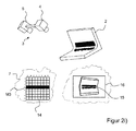
- FIG. 1 shows a sketch of a device 1 for the three-dimensional optical measurement of objects 2 with a topometric sensor 3 to avoid measurement errors due to multiple reflections.
- the topometric sensor 3 comprises a projection unit 4 and at least one image acquisition unit 5.
- the projection unit 4 has a light source 6, a programmable pattern generator 7 with separately controllable individual elements and projection optics 8.
- the topometric sensor 3 further comprises at least one image acquisition unit 5, which is an imaging element 9 and a receiving optics 10 has.
- the topometric sensor 3 is connected to a control unit 11. This is set up so that the topometric sensor 3 can perform measurements in which the pattern generator 7 of the projection unit 4 projects a specific pattern. In particular, patterns can be projected in which only one or more projection pattern segments of the pattern generator 7 illuminate the object 2 to be measured.
- a projection pattern segment is in each case a selected individual element or a contiguous group of adjacent individual elements of the imaging element.
- the control unit 11 is connected to an evaluation unit 12. Furthermore, a display unit 13 is provided which is connected at least to the evaluation unit 12 and the user displays the measurement image 16 or a modified measurement image 17 recorded by the at least one image recording unit 5.
- the evaluation unit 12 analyzes the measurement images recorded by the at least one image recording unit 5 in order to determine the partial surfaces which have arisen by direct or indirect reflection of the pattern, wherein only one or more projection pattern segments of the pattern generator 7 illuminate the object 2 to be measured.
- the measurement images 16 analyzed by the evaluation unit 12 can optionally be modified measurement images 17, in which the measurement images recorded by the image acquisition unit 5 are modified by the influence of the background illumination.
- the evaluation unit 12 is set up to generate at least one projection mask after evaluation of all (possibly modified) measurement images.
- the evaluation unit 12 is preferably suitable for this purpose to carry out the necessary data processing steps with a computer program.
- FIGS. 2a) to 2i illustrate the first embodiment of the method for the three-dimensional optical measurement of objects with the device FIG. 1 using a schematic example.
- FIG. 2a shows a recording configuration for a measurement alignment of the topometric sensor 3 on the object 2.
- the object 2 is to be measured by the topometric sensor 3, which includes a projection unit 4 and an image pickup unit 5, so that no measurement errors due to multiple reflections occur.
- the projection unit 4 contains for this purpose a programmable pattern generator 7 with separately controllable individual elements.
- a programmable pattern generator 7 may include, for example, a digital micromirror device DMD, a liquid crystal display LCD or a liquid crystal on a silicon substrate LCoS.
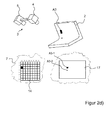
- FIG. 2b omits a sketch of the measurement setup FIG. 2a ) with a definition of the projection pattern segments 14 of the programmable pattern generator 7 and the projection of the projection pattern segments 14 on the object 2 recognize.
- FIG. 2b the outlines of the defined projection pattern segments 14 are projected onto the object 2.
- FIG. 2b bottom left, the two-dimensional representation of the pattern generator 7 with the 64 defined projection pattern segments 14.
- Each segment is uniquely identified by a row and column numbering (eg A1, B1, ... H8).
- FIG. 2 b) at the bottom right shows the associated measurement image 16, which is recorded with the imaging element 9 of the image acquisition unit 5 of this configuration. Again, the recorded segment boundaries of the projection pattern segments 14 are shown on the object 2 in the measurement image 16 for better understanding.
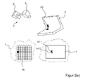
- a measurement image 16 is now respectively recorded by the image acquisition unit 5, in which the respectively associated projection pattern segment 14 of the programmable pattern generator 7 illuminates the object 2 exclusively.
- this process of illuminating the object is sequentially outlined sequentially by the individual projection pattern segments (14) for the segments A1, A3, A4 and A5.
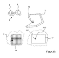
- a calibration measurement image of the object 2 is taken by the image recording unit 5, in which the object 2 is not illuminated by the projection unit 4.
- the calibration measurement image thus contains the information about the influence of a constant background illumination, which also occurs in the later measurements with illumination by selected projection pattern segments 14.
- This calibration measurement image is used to calculate a modified measurement image 17 used for the later evaluation by subtracting from each measurement image 16 for a particular projection pattern segment 14 the calibration measurement image without illumination by the projection unit 4.
- the influence of the backlight (ignoring brightness change and noise) is eliminated mathematically.
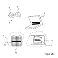
- the modified measuring images 17 of the projection pattern segments A1, A3, A4 and A5, which are each formed by subtraction, ie by subtraction, are shown.
- the reflected partial surfaces 15 are then determined in all modified measuring images 17.
- the detection of these partial surfaces 15 may, for. B. by the application of a gray value threshold. All pixels of the (possibly modified) measurement image 16 (17) above a threshold defined a priori are recognized as partial areas.
- the respective partial surface 15 is a direct or indirect reflection surface.
- all possible combinations of two (possibly modified) measurement images are analyzed by the evaluation unit 12 by suitable programming. For each combination, it is checked whether the respective sub-areas 15 overlap in the identical image areas. If there is an overlap, the two associated projection pattern segments 14 must not illuminate the object 2 at the same time, since then the overlapping of the projected partial patterns of the two projection pattern segments 14 in the image acquisition unit 5 can occur. If the two (possibly modified) measurement images do not include any common subareas 15, then the two associated projection pattern segments 14 can jointly illuminate the object 2, since no superimposition of the subpatterns takes place in the image acquisition unit 5.
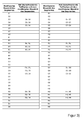
- FIG. 2 are the results of the overlap analysis of the (possibly modified) measurement images in FIG. 3 listed.
- each projection pattern segment A1 to H8 it is listed whether overlapping partial surfaces 15 with the (optionally modified) measurement image of other projection pattern segments occur during the projection with this projection pattern segment A1 to H8.
- So z. B. for the projection pattern segment A3 found that its sub-areas also superimpose the projection pattern segments A4 and A5 associated sub-surfaces 15 in the recorded (possibly modified) measurement image.
- the partial surfaces 15 contained in the (possibly modified) measurement image do not overlap with partial surfaces 15 of another (modified) measurement image. So you can easily share illuminate the object 2, since it does not come in the image pickup unit 5 to a superposition of the pattern signals.
- the evaluation unit is set up by suitable programming in order to record in the first projection mask all the projection pattern segments 14 whose (modified) measurement images have no common sub-areas 15 with other (modified) measurement images. Subsequently, it is advisable to test the other projection pattern segments 14, which may not be projected together with other projection pattern segments 14, with regard to their possible assignment to the first projection mask. If the respective potentially to be added projection pattern segment 14 no overlapping sub-areas 15 with one of the previous projection pattern segments 14 of the respective projection screen in the associated (modified) measurement images 16 (17), this projection pattern segment 14 can be added to this projection mask. For the optional following projection masks can be proceeded very similar.
- the measurement of the projection pattern segments A3, B3, C3, D3, E3, F3, G3 and H3 have no common sub-areas 15 with the projection pattern segments the previous first projection mask M1. They are therefore added to the first projection mask M1.
- projection pattern segments A3, B3, C3, D3, E3, F3, G3 and H3 could have been added instead.
- An alternative useful extension of the projection mask M1 would be z.
- the projection mask M1 would consist of two compact, completely filled partial masks.
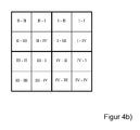
- each quadrant I to IV is subsequently subdivided into four equally sized subquadrants following the same principle.
- the second tree structure level thus comprises 16 elements II to IV-IV, wherein the first quadrant name of the quadrant pairs of the quadrant of the parent tree structure level FIG. 4a ) and the following quadrant designation the respective subquadrants.
- Each element of the second tree structure level is again decomposed analogously into four quadrants. This is in Figure 4c ) recognizable.
- the elements of the third tree structure level are thus identical to the a priori defined projection pattern segments 14 from the embodiment described above.
- the individual elements are thus declared by three consecutive quadrant designations, the first quadrant designation corresponding to the quadrant in the first tree structure plane FIG. 4a ), the middle quadrant designation of the quadrants in the second tree structure level according to FIG. 4b ) and the last quadrant designation according to the sub-sub quadrant in the third tree structure plane Figure 4c ).
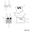
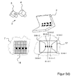
- FIG. 5a exemplifies the device FIG. 1 and 2a ), in the example of each one of the three defined tree structure levels FIGS. 4a) to 4c ) is highlighted.
- This is the element I of the first tree structure plane (characterized by the completely blackened surface), the element II-II of the second tree structure plane (characterized by the blackened triangles) and the element IV-I-IV of the third tree structure plane (indicated by the blackened rhombus).
- a measurement image 16 is respectively taken by the image acquisition unit 5, in which the respectively associated tree structure element of the programmable pattern generator 7 illuminates the object 2 exclusively.
- the reflected partial surfaces 15 are determined in all (possibly modified by subtraction with the Kalibriermesstruck) measurement images.
- all possible combinations of two (modified) measurement images of the first tree structure level are analyzed. Analogously to the described procedure of the first embodiment, it is checked in each combination whether the respective sub-areas 15 overlap in identical image areas. The results of this overlap analysis are in FIG. 6 listed in tabular form.
- the 16 original measurements of the second tree structure level can thus be reduced to eight measurements.
- FIG. 5d it can be seen that for the subordinate projection pattern segments B5, D5, F5 and H5, ie for the projection pattern segments III-II, III-II-I, IV-II and IV-II-I multiple reflections in the area above occur.
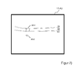
- FIG. 7 is the modified measurement image 17-A3 off Figure 2d ) enlarged.
- the two partial surfaces A3-1 and A3-2 are detected.
- the contour of the partial surfaces 15 is shown. Since the inner and outer orientations of the projection unit 4 and of the image acquisition unit 5 are known, the epipolar lines E1, E2, E3 and E4 of the four vertices of the projection pattern segment A3 can be drawn into the modified measurement image 17-A3.
- the partial area of the object 2 which is illuminated by a projection pattern segment 14 is, to a good approximation, a plane area, provided that the size of the partial area is only sufficiently small.
- a straight line is shown as a straight line.
- the area illuminated on the object 2 by the respectively active projection pattern segment 14 is a quadrangle with, to a good approximation, straight boundary lines.
- the subarea A3-2 of the modified measurement image 17-A3 is produced by a two-fold reflection on the object 2. Its geometric shape is significantly more indefinite. Likewise, the contrast, ie the gray value difference between partial area and background, is significantly weaker. Furthermore, it can be clearly seen that this subarea A3-2 has no relation to the epipolar lines of the vertices of the projection pattern segment A3. In contrast, the partial area A3-1 is encompassed by the epipolar lines. The four corner points of the sub-area A3-1 lie exactly on the associated epipolar line of the associated vertex of the projection pattern segment A3 on the pattern generator 7. On the basis of this analysis, the sub-area A3-1 as direct reflection surface and the sub-area A3-2 as indirect Reflection surface are classified.
- FIG. 8 shows in a common representation the detected partial areas A3-1, A3-2 (hatched highlighted), the partial areas A4-1 and A4-2 (hatched highlighted) for the segments A3 and A4 and the epipolar lines E1, E2, E3 and E4 for the segment A3, as well as the epipolar lines E5, E6, E7 or E8 for the segment A4.
- the subareas A4-1 and A4-2 can also be classified.
- the neighborhood approach can be used here.
- the two indirect sub-areas A3-2 and A4-2 overlap. According to the previous method, therefore, the two associated segments A3 and A4 must not be contained in a common projection mask, since their associated sub-areas overlap in the modified measurement images 17. Since, however, only the direct partial surfaces are to be evaluated with the later measurement with a projection mask, an overlap of these two indirect partial surfaces is irrelevant. Thus, the projection pattern segments A3 and A4 can nevertheless be contained within a projection mask.
- the direct reflection surfaces between two directly adjacent segments also overlap.
- the causes are typically blurring phenomena due to the imperfection of the projection optics 8 or receiving optics 10.
- a blurred projection or image may occur if the object 2 is outside the focal plane of the projection unit 4 or the image recording unit 5. In the previously outlined embodiments, this effect has not been considered.
- various adjacent projection pattern segments 14 should not be part of a common projection mask in the implementation of the method.
- the number of necessary projection masks would thus increase significantly.
- the resulting projection masks would contain a plurality of isolated projection pattern segments 14 (ie projection pattern segments without illumination of the direct neighboring segments).
- the overlap of direct reflection surfaces in the modified measurement image 17 is just as innocuous as the overlap of indirect reflection surfaces. It is only necessary to prevent the overlapping of direct and indirect reflection surfaces.
- projection masks with many isolated elements can be used due to overlapping direct faces due to the blurring overlapping direct faces avoided.
- FIG. 9 shows for the application example FIG. 2 the excluding projection pattern segments 14, in which the respective direct reflection surface of the one projection pattern segment overlap with at least one indirect reflection surface of the other projection pattern segment.
- FIG. 3 With regard to the overlapping of subareas without prior classification, it is shown that various exclusionary projection pattern segments 14 have been omitted within a projection mask in the standard method described at the outset. Since in these cases only indirect sub-areas overlap, which should not be evaluated anyway, they can still be illuminated together in the optimized mask generation.
- the area of the object 2 illuminated by the projection unit 4 can be measured with only two instead of three projection masks without the influence of measurement errors due to multiple reflections.
- the second projection mask M2 remains in the previously described form FIG. 2h ) consist.
Abstract
Ein Verfahren zum dreidimensionalen optischen Vermessen von Objekten (2) mit einem topometrischen Messverfahren mittels Projektion mindestens eines Musters auf ein Objekt (2) mit einem Mustergenerator (7) und Aufnehmen mindestens einer Abbildung des Objektes (2) mit dem aufprojizierten Muster mit mindestens einer Bildaufnahmeeinheit (5) zur topometrischen Vermessung des Objektes (2) wird beschrieben. Das Verfahren hat die Schritte: a) Ermitteln von Teilflächen (15) in mindestens einer Abbildung je beteiligter Bildaufnahmeeinheit (5) des Objektes (2), die ein von dem Objekt (2) rückgestreutes Signal eines jeweils auf das Objekt (2) projizierten Projektionsmuster-Segmentes (14) des Mustergenerators (7) enthalten, b) Erstellen von mindestens einer Projektionsmaske (M i ; i ˆˆ N \{0})), welche jeweils mindestens ein Projektionsmuster-Segment (14) umfasst, wobei die Projektionsmuster-Segmente (14) einer Projektionsmaske (M i ) so ausgewählt sind, dass sich die ermittelten Teilflächen (15) der Projektionsmuster-Segmente (14) in der mindestens einen Abbildung je beteiligter Bildaufnahmeeinheit (5) nicht gegenseitig überlappen, und c) Durchführen der topometrischen Vermessung des Objektes (2) jeweils durch Projektion mindestens eines Musters mittels der mindestens einen erstellten Projektionsmaske (M i ; i ˆˆ N \{0}).A method for three-dimensional optical measuring of objects (2) with a topometric measuring method by projection of at least one pattern on an object (2) with a pattern generator (7) and recording at least one image of the object (2) with the aufprojizierten pattern with at least one image pickup unit (5) for topometric measurement of the object (2) will be described. The procedure has the steps: a) Determining partial surfaces (15) in at least one image per participating image acquisition unit (5) of the object (2), which is a backscattered from the object (2) signal of each of the object (2) projected projection pattern segment (14) Pattern generator (7) included, b) creating at least one projection mask (M i; i N \ {0})), which in each case comprises at least one projection pattern segment (14), wherein the projection pattern segments (14) of a projection mask (M i) are selected in that the determined subareas (15) of the projection pattern segments (14) do not overlap one another in the at least one image per each involved image acquisition unit (5), and c) performing the topometric measurement of the object (2) in each case by projection of at least one pattern by means of the at least one created projection mask (M i; i N \ {0}).
Description
Die Erfindung betrifft ein Verfahren zum dreidimensionalen optischen Vermessen von Objekten mit einem topometrischen Messverfahren mittels Projektion mindestens eines Musters auf ein Objekt mit einem Mustergenerator und Aufnehmen mindestens einer Abbildung des Objektes mit dem aufprojizierten Muster mit mindestens einer Bildaufnahmeeinheit zur topometrischen Vermessung des Objektes.The invention relates to a method for the three-dimensional optical measurement of objects with a topometric measuring method by projection of at least one pattern onto an object with a pattern generator and recording at least one image of the object with the aufprojizierten pattern with at least one image pickup unit for topometric measurement of the object.
Die Erfindung betrifft weiterhin eine Vorrichtung zum dreidimensionalen optischen Vermessen von Objekten mit einem topometrischen Messverfahren, wobei die Vorrichtung einen topometrischen Sensor, der mindestens eine Projektionseinheit zur Beleuchtung von Teilflächen eines Objektes mit wahlweisen Projektionsmuster-Segmenten eines auswählbaren Projektionsmusters und mindestens eine Bildaufnahmeeinheit umfasst, sowie eine Steuereinheit und eine Auswerteeinheit zur topometrischen Auswertung der mit der Bildaufnahmeeinheit aufgenommenen Bilder des zu vermessenden Objektes beinhaltet.The invention further relates to a device for the three-dimensional optical measurement of objects with a topometric measuring method, wherein the device comprises a topometric sensor comprising at least one projection unit for illuminating partial areas of an object with optional projection pattern segments of a selectable projection pattern and at least one image acquisition unit, and a Control unit and an evaluation unit for topometric evaluation of the recorded with the image pickup unit images of the object to be measured includes.
Die Erfindung betrifft weiterhin ein Computerprogramm mit Programmcodemitteln zur Durchführung des oben beschriebenen Verfahrens, wenn das Computerprogramm auf einer Datenverarbeitungseinrichtung ausgeführt wird.The invention further relates to a computer program with program code means for carrying out the method described above when the computer program is executed on a data processing device.
Die dreidimensionale optische Erfassung von Objektoberflächen mittels optischer Triangulationssensoren nach dem Prinzip der Topometrie ist hinreichend bekannt. Hierbei werden Muster, insbesondere Streifenmuster, auf das zu vermessende Objekt projiziert. Das rückgestreute Muster wird von einer oder mehreren Bildaufnahmeeinheiten (in der Regel Kameras) aufgenommen und anschließend durch eine Bildauswerteeinheit ausgewertet.The three-dimensional optical detection of object surfaces by means of optical triangulation sensors according to the principle of topometry is sufficient known. In this case, patterns, in particular stripe patterns, are projected onto the object to be measured. The backscattered pattern is recorded by one or more image acquisition units (usually cameras) and then evaluated by an image evaluation unit.
Die durch die Projektionseinheit projizierten Muster können mannigfaltig ausgestaltet sein. Typische projizierte Muster sind stochastische Muster sowie regelmäßige Muster, z. B. Punkt- und Streifenmuster. Insbesondere Streifenmuster haben sich als gängige Muster im Rahmen der optischen 3D-Messung etabliert.The patterns projected by the projection unit can be variously designed. Typical projected patterns are stochastic patterns as well as regular patterns, e.g. B. Dot and Strip Patterns. In particular, stripe patterns have established themselves as common patterns in the context of optical 3D measurement.
Durch das projizierte Muster entsteht auf dem zu vermessenden Objekt eine künstliche, temporäre Textur. Diese wird durch eine oder mehrere Bildaufnahmeeinheiten erfasst. Anhand der künstlich erzeugten, im allgemeinen a priori bekannten Textur können beleuchtete 3D-Punkte auf dem zu vermessenden Objekt eindeutig sowohl in der Projektionseinheit, als auch der einen oder mehreren Bildaufnahmeeinheiten identifiziert werden.The projected pattern creates an artificial, temporary texture on the object to be measured. This is detected by one or more image acquisition units. On the basis of the artificially produced, generally a priori known texture illuminated 3D points on the object to be measured can be uniquely identified in both the projection unit, and the one or more image recording units.
Durch ein Triangulationsverfahren (im Allgemeinen durch Vorwärtsschnitt) können die 3D-Koordinaten bestimmt werden. Dazu muss der gleiche Objektpunkt in mindestens zwei räumlich verschiedenen Aufnahmepositionen gemessen werden. Die Projektionseinheit kann dabei als inverse Kamera fungieren, so dass zur Bestimmung der 3D-Koordinaten die Messung mit einer Kamera ausreicht. In vielen Fällen kann es jedoch hilfreich sein, mehrere Kameras zur Erfassung der projizierten Textur zu verwenden. Die Projektionseinheit wird oftmals nur als Texturgeber genutzt und nicht bei der 3D-Punkt-Berechnung berücksichtigt, da die innere und äußere Orientierung der Projektionseinheit aufgrund ihrer im Vergleich zu einer Kamera großen Masse und höheren Temperatur (aufgrund der Strahlungsquelle) häufig instabiler als für die beteiligten Kameras ist.By a triangulation method (generally by forward cutting) the 3D coordinates can be determined. For this, the same object point must be measured in at least two spatially different recording positions. The projection unit can act as an inverse camera, so that sufficient to determine the 3D coordinates, the measurement with a camera. In many cases, however, it may be helpful to use multiple cameras to capture the projected texture. The projection unit is often used only as a texturizer and not considered in the 3D point calculation, since the internal and external orientation of the projection unit often because of their large mass and higher temperature (due to the radiation source) compared to a camera unstable than for those involved Cameras is.
Die Projektionseinheit umfasst drei Kernbestandteile. Diese sind eine Beleuchtungseinheit, ein Mustergenerator und eine Projektionsoptik. Die Beleuchtungseinheit stellt elektromagnetische Strahlung bereit. Je nach Ausführung der Beleuchtungseinheit wird elektromagnetische Strahlung mit charakterisierenden Eigenschaften erzeugt. Diese sind insbesondere der Wellenlängenbereich, in dem die Lichtquelle Strahlung emittiert, sowie die Leistung.The projection unit comprises three core components. These are a lighting unit, a pattern generator and a projection optics. The lighting unit provides electromagnetic radiation. Depending on the design of the lighting unit electromagnetic radiation is generated with characterizing properties. These are in particular the wavelength range in which the light source emits radiation and the power.
Der Mustergenerator erzeugt ein Muster, welches durch die Beleuchtungseinheit beleuchtet wird. Anschließend wird das Muster mit Hilfe der Projektionsoptik auf das zu vermessende Objekt projiziert. Der Mustergenerator kann mannigfaltig ausgestaltet sein. So können z. B. Glasdias verwendet werden, welche das zu projizierende Muster enthalten. Es ist ebenfalls möglich, dass das Dia bezüglich der Lichtquelle in Bewegung gebracht wird (z. B. Rotation und/oder Translation). Darüber hinaus können programmierbare Displays, wie Liquid-Crystal-on-Silicon (LCoS), Liquid-Crystal-Display (LCD) und digitale Mikrospiegeleinheiten (Digital Micromirror Device - DMD) eingesetzt werden. Sie zeichnen sich durch getrennt ansteuerbare Einzelelemente aus. Je nach Ausführungsform werden Sie als Pixel (LCoS, LCD) bzw. als Mikrospiegel (DMD) bezeichnet. Programmierbare Mustergeneratoren mit programmierbaren Displays bieten eine Reihe von Vorteilen gegenüber analogen Mustergeneratoren. Insbesondere können prinzipiell unendlich verschiedene Muster projiziert werden.The pattern generator generates a pattern which is illuminated by the illumination unit. Subsequently, the pattern is projected onto the object to be measured with the aid of the projection optics. The pattern generator can be designed manifold. So z. As glass slides are used which contain the pattern to be projected. It is also possible that the slide is made to move with respect to the light source (eg, rotation and / or translation). In addition, programmable displays such as liquid crystal on silicon (LCoS), liquid crystal display (LCD) and digital micromirror device (DMD) can be used. They are characterized by separately controllable individual elements. Depending on the embodiment, they are referred to as pixels (LCoS, LCD) or micromirrors (DMD). Programmable pattern generators with programmable displays offer a number of advantages over analog pattern generators. In particular, infinitely different patterns can be projected in principle.
Die präzise Bestimmung des abgebildeten Objektpunktes in der jeweiligen Bildaufnahmeeinheit setzt in der Regel voraus, dass das vom Objekt rückgestreute Mustersignal nicht durch andere Signale, insbesondere weitere, anders artige Mustersignale, signifikant überlagert wird. Je nach den Eigenschaften dieser zusätzlichen Signale (z. B. zeitliche Konstanz, Intensität, etc.) sowie des Musterprojektionsverfahrens reichen die Auswirkungen von einer Verschlechterung des Signal-Rausch-Verhältnisses bis zu einer systematischen Verfälschung der Mustermessung.The precise determination of the imaged object point in the respective image recording unit generally requires that the pattern signal backscattered by the object is not significantly superimposed by other signals, in particular further, differently shaped pattern signals. Depending on the characteristics of these additional signals (eg, temporal constancy, intensity, etc.) as well as the pattern projection method, the effects range from a deterioration of the signal-to-noise ratio to a systematic falsification of the pattern measurement.
Ein besonderes Problem bei einem dreidimensionalen optischen Vermessen von Objekten mit einem topometrischen Messverfahren tritt dann auf, wenn das projizierte Muster auf dem beleuchteten Objekt mehrfach reflektiert wird. Dies ist abhängig von der inneren und äußeren Orientierung der Projektionseinheit, der Geometrie des Objektes, der Lage und Ausrichtung des Objektes zur Projektionseinheit, sowie den Reflexionseigenschaften des Objektes. In Abhängigkeit von der inneren und äußeren Orientierung der mindestens einen Bildaufnahmeeinheit können sich in einem Bildbereich das direkt rückgestreute Mustersignal des beobachteten Objektpunktes, sowie ein mehrfach reflektiertes anderes Mustersignal, welches ursprünglich einen anderen Objektpunkt beleuchtet hat, überlagern.A particular problem with a three-dimensional optical measuring of objects with a topometric measuring method occurs when the projected pattern is reflected several times on the illuminated object. This depends on the inner and outer orientation of the projection unit, the geometry of the object, the position and orientation of the object to the projection unit, as well as the reflection properties of the object. Depending on the inner and outer orientation of the at least one image recording unit, the directly backscattered pattern signal of the observed object point as well as a multiply reflected other pattern signal, which originally illuminated another object point, can overlap in one image area.
Die zusätzlichen Signalanteile durch Mehrfachreflexion des Musters am Objekt sind für verschiedene Muster nicht konstant. Insbesondere bei einer Streifenprojektion führen diese Mehrfachreflexionen zu fehlerhaften Phasenmessungen und nachfolgend zu falschen 3D-Punkten.The additional signal components due to multiple reflection of the pattern on the object are not constant for different patterns. Particularly in the case of a fringe projection, these multiple reflections lead to erroneous phase measurements and subsequently to incorrect 3D points.
Aus der
Ein Problem tritt jedoch dadurch auf, dass je nach Art, Beschaffenheit und ggf. Vorbehandlung des zu vermessenden Objektes die Reflexionseigenschaften deutlich unterschiedlich sind. Diese können zwischen einer idealen diffusen Reflexion über eine gerichtete Reflexion bis hin zur spiegelnden Reflexion variieren. Sie können sich sogar innerhalb eines Objektes deutlich unterschiedlich ausprägen. Darüber hinaus kann nicht nur spiegelnde Reflexion zur Mehrfachreflexion führen, welche die Mustermessung in der jeweiligen Bildaufnahmeeinheit systematisch verfälschen kann. Durch die implizite Modellannahme, dass nur spiegelnde Reflexion auftritt, wird die allgemein deutlich komplexere Realität nur unzureichend abgebildet. Dies führt zu einer suboptimalen Teilbereichsbildung, bei der weiterhin die Mustermessung in einigen Bereichen systematisch verfälscht sein kann. Weiterhin können auch Teilbereiche in Messbereichen des zu vermessenden Objektes gebildet werden, in denen die Bildung von Teilbereichen praktisch überhaupt nicht nötig ist. Zudem wird nur das Auftreten von Doppelreflexionen berücksichtigt. Es treten aber durchaus Fälle auf, in denen das Signal mehr als zweimal in dem Objekt reflektiert wird.However, a problem arises in that, depending on the nature, condition and possibly pretreatment of the object to be measured, the reflection properties are significantly different. These can vary from ideal diffuse reflection to directional reflection and specular reflection. They can even be expressed significantly differently within an object. In addition, not only specular reflection can lead to multiple reflection, which can systematically distort the pattern measurement in the respective image acquisition unit. Due to the implicit model assumption that only specular reflection occurs, the generally much more complex reality is not adequately depicted. This leads to a sub-optimal partial area formation, in which the pattern measurement can continue to be systematically falsified in some areas. Furthermore, it is also possible to form partial areas in measuring areas of the object to be measured, in which the formation of partial areas is practically unnecessary at all. In addition, only the occurrence of double reflections is taken into account. However, there are cases in which the signal is reflected more than twice in the object.
Aufgabe der vorliegenden Erfindung ist es daher, ein verbessertes Verfahren und eine Vorrichtung zum dreidimensionalen optischen Vermessen von optischen Objekten mit einem topometrischen Messverfahren zu schaffen, um Messfehler, die aus Mehrfachreflexionen des projizierten Musters an dem Objekt und einer anschließenden Überlagerung unterschiedlicher Mustersignalanteile in einer oder mehreren Bildaufnahmeeinheiten resultieren, bestmöglich zu reduzieren oder bestenfalls sogar ganz zu vermeiden.It is therefore an object of the present invention to provide an improved method and apparatus for the three-dimensional optical measurement of optical objects using a topometric measuring method Measurement errors that result from multiple reflections of the projected pattern on the object and a subsequent superposition of different pattern signal components in one or more image recording units, as best as possible to reduce or at best even completely avoided.
Die Aufgabe wird mit dem Verfahren mit den Merkmalen des Anspruchs 1 sowie mit der Vorrichtung mit den Merkmalen des Anspruchs 12 sowie das Computerprogramm mit den Programmcodemitteln mit den Merkmalen des Anspruchs 17 gelöst.The object is achieved with the method having the features of
Vorteilhafte Ausführungsformen sind in den Unteransprüchen beschrieben.Advantageous embodiments are described in the subclaims.
Bei dem erfindungsgemäßen Verfahren sind folgende Schritte vorgesehen:
- a) Ermitteln von Teilflächen in mindestens einer Abbildung je beteiligter Bildaufnahmeeinheit des Objektes, die ein von dem Objekt rückgestreutes Signal eines jeweils auf das Objekt projizierten Projektionsmuster-Segmentes des Mustergenerators enthalten,
- b) Erstellen von mindestens einer Projektionsmaske, welche jeweils mindestens ein Projektionsmuster-Segment umfasst, wobei die Projektionsmuster-Segmente einer Projektionsmaske so ausgewählt sind, dass sich die ermittelten Teilflächen der Projektionsmuster-Segmente in der mindestens einen Abbildung je beteiligter Bildaufnahmeeinheit nicht gegenseitig überlappen, und
- c) Durchführen der topometrischen Vermessung des Objektes jeweils durch Projektion mindestens eines Musters mittels der mindestens einen erstellten Projektionsmaske.
- a) determining partial areas in at least one image per participating image acquisition unit of the object, which contain a signal, which is backscattered by the object, of a projection pattern segment of the pattern generator projected onto the object,
- b) creating at least one projection mask, which in each case comprises at least one projection pattern segment, wherein the projection pattern segments of a projection mask are selected such that the determined subareas of the projection pattern segments do not overlap one another in the at least one image per participating image acquisition unit, and
- c) Performing the topometric measurement of the object in each case by projection of at least one pattern by means of the at least one created projection mask.
Das auf ein Objekt aufprojizierte Muster wird somit in definierte Segmente z. B. durch geeignete Programmierung eines Mustergenerators unterteilt. Für jedes Projektionsmuster-Segment werden nun Teilflächen in der mindestens einen Abbildung ermittelt, die das rückgestreute Signal dieses Projektionsmuster-Segmentes am Objekt enthalten. Sofern mehrere Bildaufnahmeeinheiten verwendet werden, muss für jede Bildaufnahmeeinheit exklusiv analysiert werden, welche Teilflächen sich überlappen. Hieraus wird dann mindestens eine Projektionsmaske derart erstellt, dass sich durch verschiedene Projektionsmuster-Segmente eines Projektionsmusters beleuchtete Teilflächen je beteiligter Bildaufnahmeeinheit nicht überlagern. Anschließend wird die topometrische Messung des Objekts durch Projektion des Musters mittels der mindestens einen erstellten Projektionsmaske durchgeführt. Bei Mehrfachreflexionen, die durch Projektion des vollständigen Musters auf das Objekt auftreten würden, ergeben sich dann mehrere Projektionsmasken, die getrennt nacheinander auf das Objekt projiziert werden. Für den Sonderfall, dass keine streuenden Reflexionen auftreten, kann die topometrische Messung des Objektes mit Hilfe einer einzigen Projektionsmaske durchgeführt werden, die dann das gesamte Muster enthält. Diese einzige Projektionsmaske ist dann aber ein Resultat der vorherigen Überprüfung, ob tatsächlich keine Überschneidung von beleuchteten Teilflächen durch einzelne Projektionsmuster-Segmente auftreten.The aufprojizierte on an object pattern is thus in defined segments z. B. divided by appropriate programming a pattern generator. For each projection pattern segment, subareas in the at least one image are determined, which are the backscattered signal of this projection pattern segment included on the object. If several image acquisition units are used, it must be exclusively analyzed for each image acquisition unit which subareas overlap. From this, at least one projection mask is then created in such a way that, due to different projection pattern segments of a projection pattern, illuminated subareas per participating image acquisition unit do not overlap. Subsequently, the topometric measurement of the object is carried out by projection of the pattern by means of the at least one created projection mask. In the case of multiple reflections, which would occur by projecting the complete pattern onto the object, then several projection masks result, which are projected separately one after the other onto the object. For the special case that no scattering reflections occur, the topometric measurement of the object can be carried out with the aid of a single projection mask, which then contains the entire pattern. However, this single projection mask is then a result of the previous check as to whether there actually is no overlap of illuminated partial surfaces by individual projection pattern segments.
Wie bereits erläutert wurde, kann die Erfindung mit einem topometrischen Sensor durchgeführt werden, der eine oder mehrere Bildaufnahmeeinheiten beinhaltet. Sofern mehr als eine Bildaufnahmeeinheit verwendet wird, muss die Analyse der Teilflächen je zugehörigem Projektionsmuster-Segment hinsichtlich einer Überschneidung mit einer oder mehreren anderen Teilflächen einer oder mehreren zugehörigen Projektionsmuster-Segmenten in jeder Bildaufnahmeeinheit getrennt erfolgen. Es werden also explizit keine Teilflächen aus Abbildungen von verschiedenen Bildaufnahmeeinheiten hinsichtlich Überschneidungen abgeglichen. Zur Erstellung der Projektionsmasken werden die Überschneidungsergebnisse je Bildaufnahmeeinheit aber zusammen betrachtet. So können zum Beispiel nur dann zwei Projektionsmuster-Segmente Teil einer gemeinsamen Projektionsmaske sein, wenn ihre zugehörigen Teilflächen jeweils getrennt betrachtet in jeder beteiligten Bildaufnahmeeinheit jeweils keine überschneidenden Teilflächen aufweisen.As already explained, the invention can be carried out with a topometric sensor which includes one or more imaging units. If more than one image acquisition unit is used, the analysis of the subareas per associated projection pattern segment must be separate with respect to an overlap with one or more other subareas of one or more associated projection pattern segments in each image capture unit. Thus, no sub-areas of images of different image-recording units are explicitly matched with respect to overlaps. To create the projection masks, however, the overlap results per image acquisition unit are considered together. Thus, for example, only two projection pattern segments can be part of a common projection mask if their associated sub-areas, viewed separately in each case, have no overlapping partial areas in each participating image acquisition unit.
Das Verfahren hat den Vorteil, dass keine impliziten Annahmen für das Reflexionsverhalten erforderlich sind sowie die Lage und Ausrichtung des Objektes zum topometrischen Sensor nicht bekannt sein muss. Deshalb ist keine vorherige dreidimensionale Vermessung des Objektes erforderlich. Mit dem Verfahren kann eine Verfälschung des Messergebnisses auch bei Auftreten von Mehrfachreflexionen ausgeschlossen werden.The method has the advantage that no implicit assumptions for the reflection behavior are required and the position and orientation of the object to the topometric sensor need not be known. Therefore, no prior three-dimensional measurement of the object is required. With the method, a falsification of the measurement result can be excluded even if multiple reflections occur.
Das Verfahren und die zur Durchführung dieses Verfahrens eingerichtete Vorrichtung beruhen auf der Überlegung, dass Messfehler genau dann auftreten, wenn sich im jeweiligen Messbild unterschiedliche Signalanteile des auf das Objekt projizierten und anschließend an diesem zurückgestreuten Musters an der auszuwerten Bildposition überlagern, wobei Mehrfachreflexionen des Musters für die Überlagerung und die daraus resultierenden Messfehler ursächlich sind. Eine ungestörte Messung wird dann ermöglicht, wenn im Rahmen einer Messung eines Musters an einer oder mehreren auszuwertenden Bildpositionen durch selektive Projektion eines Teils des ursprünglichen Musters die Überlagerungen vermieden werden. Hierzu ist die Information erforderlich, welche Musteranteile sich an der jeweiligen auszuwertenden Bildposition überlagern. Genau diese Musteranteile dürfen dann nicht gleichseitig projiziert werden. Diese Information kann beispielsweise dadurch gewonnen werden, dass jeder Musteranteil, d. h. jedes Projektionsmuster-Segment, einzeln projiziert wird, wobei jeweils ein Messbild pro beteiligter Bildaufnahme aufgenommen und nachfolgend alle Messbilder hinsichtlich reflektierter Musteranteile für jede Bildposition ausgewertet werden. Die Kenntnis darüber, ob der jeweilig reflektierte Musteranteil aus einer direkter Reflexion, d. h. einer einmaligen Reflexion am Objekt, oder einer indirekten Reflexion, d. h. einer Mehrfachreflexion am Objekt, herrührt, spielt dabei keine Rolle.The method and the device set up for carrying out this method are based on the consideration that measurement errors occur precisely when different signal components of the pattern projected onto the object and then backscattered at the respective measurement image are superimposed on the image position to be evaluated, with multiple reflections of the pattern for the overlay and the resulting measurement errors are the cause. An undisturbed measurement is made possible when, as part of a measurement of a pattern at one or more image positions to be evaluated by selective projection of a portion of the original pattern, the overlays are avoided. For this purpose, the information is required, which sample shares are superimposed on the respective image position to be evaluated. Exactly these patterns must not be projected on the same side. This information can be obtained, for example, in that each pattern component, i. H. each projection pattern segment, is projected individually, wherein in each case one measurement image recorded per participating image capture and subsequently all measurement images are evaluated with respect to reflected pattern portions for each image position. The knowledge of whether the respective reflected pattern component from a direct reflection, d. H. a one-time reflection on the object, or an indirect reflection, d. H. a multiple reflection on the object, does not matter.
Der Schritt a) des Ermittelns der Teilflächen in mindestens einer Abbildung des Objektes je beteiligter Bildaufnahmeeinheit kann beispielsweise dadurch erfolgen, dass das Objekt mittels Projektion durch mindestens ein Projektionsmuster-Segment beleuchtet wird. Dann werden die Teilflächen in der mindestens einen Abbildung je beteiligter Bildaufnahmeeinheit detektiert, die ein vom beleuchteten Objekt rückgestreutes Signal eines jeweils projizierten Projektionsmuster-Segmentes des Mustergenerators enthalten. Daraufhin erfolgt ein Zuordnen der detektierten Teilflächen jeweils zu einem zugehörigen Projektionsmuster-Segment.The step a) of determining the partial areas in at least one image of the object per participating image acquisition unit can take place, for example, by that the object is illuminated by projection through at least one projection pattern segment. Then, the subareas are detected in the at least one image per participating image acquisition unit, which contain a backscattered from the illuminated object signal of each projected projection pattern segment of the pattern generator. Thereupon, the detected subareas are assigned to an associated projection pattern segment.
Dieses Ermitteln der Teilflächen kann sequentiell für sich nicht überlappende Projektionsmuster-Segmente zeitlich hintereinander erfolgen. Im einfachsten Fall wird das gesamte Projektionsmuster in eine Vielzahl von z. B. rechteckförmigen Projektionsmuster-Segmenten aufgeteilt und das Objekt dann sequentiell hintereinander exklusiv mit jeweils einem Projektionsmuster-Segment ausgeleuchtet. Es wird dann erfasst, welche Teilflächen von jeweils einem Projektionsmuster-Segment beleuchtet werden. Hieraus kann dann z. B. mit Hilfe einer Ausschlusstabelle festgelegt werden, welche Projektionsmuster-Segmente gleichzeitig auf ein Objekt projiziert werden können, ohne dass sich von den mehreren Projektionsmuster-Segmenten beleuchtete Teilflächen überschneiden.This determination of the subareas can take place sequentially for non-overlapping projection pattern segments in succession. In the simplest case, the entire projection pattern in a variety of z. B. segmented rectangular projection pattern segments and the object then sequentially sequentially lit exclusively with one projection pattern segment. It is then detected which partial areas are illuminated by a respective projection pattern segment. It can then z. For example, with the help of an exclusion table, it is possible to determine which projection pattern segments can be projected onto an object at the same time, without intersecting illuminated faces of the several projection pattern segments.
Denkbar ist aber auch, dass das Ermitteln der Teilflächen parallel für mehrere sich nicht überlappende Projektionsmuster-Segmente zeitlich zusammen erfolgt.However, it is also conceivable that the determination of the partial surfaces takes place in parallel for a plurality of non-overlapping projection pattern segments in time.
Bei der Projektion von Projektionsmuster-Segmenten des Mustergenerators auf ein Objekt beleuchten diese aktivierten Projektionsmuster-Segmente das Objekt exklusiv, ohne das andere Bereiche der Fläche eines Mustergenerators aktiv sind und elektromagnetische Strahlung in diesen Bereichen auf das Objekt abgeben.In projecting projection pattern segments of the pattern generator onto an object, these activated projection pattern segments exclusively illuminate the object without other areas of the surface of a pattern generator being active and emitting electromagnetic radiation in those areas onto the object.
Unter dem Begriff Objekt ist im Rahmen dieser Erfindung nicht nur der primär zu vermessenden Gegenstand zu verstehen. Vielmehr umfasst dieser Begriff auch die Summation eines oder mehrerer zu vermessender Gegenstände sowie die sie gegebenenfalls umgebenden Hintergrundkörper. Für das Verfahren und die Vorrichtung ist es unerheblich, welches Objekt (z.B. primär zu vermessender Gegenstand und/oder Hintergrundkörper) für die Mehrfachreflexion verantwortlich ist. Dies ist im Allgemeinen auch nicht möglich, da die Position und Ausrichtung des zu vermessenden Gegenstands für das Verfahren nicht vorbekannt sein muss. Die spätere Aufspaltung der 3D-Daten in die Messdaten, welche den zu vermessenden Gegenstand betreffen und die Messdaten, welche den umgebenden Hintergrundkörper betreffen ist dagegen eine Standard-Teilaufgabe im Rahmen der topometrischen Messung. Dafür gibt es eine Vielzahl von Methoden. Sie sind nicht Teil der Erfindung und werden als zum fachmännischen Können zählend deswegen nicht weiter beschrieben.The term object is not only the primary in the context of this invention to understand the object to be measured. Rather, this term also encompasses the summation of one or more objects to be measured and the background bodies possibly surrounding them. For the method and the device, it does not matter which object (eg object to be measured primarily and / or background body) is responsible for the multiple reflection. This is generally not possible, since the position and orientation of the object to be measured for the process need not be previously known. The subsequent splitting of the 3D data into the measurement data, which relate to the object to be measured and the measurement data, which relate to the surrounding background body, however, is a standard subtask within the scope of the topometric measurement. There are a variety of methods for this. They are not part of the invention and are therefore not further described as including those of skill in the art.
Vorzugsweise erfolgt das Ermitteln der Teilflächen ohne Berücksichtigung eines für die spätere topometrischen Messung genutzten speziellen Musters, wie beispielsweise eines Streifenmusters, sondern erfolgt einfach durch Aktivierung eines Bereichs des Mustergenerators und des zugehörigen Projektors so, dass das Objekt durch Aktivierung des Segmentes ausschnittsweise einfach mit gleichmäßiger elektromagnetischer Strahlung beaufschlagt wird.Preferably, the determination of the sub-areas without taking account of a used for the later topometric measurement special pattern, such as a stripe pattern, but simply by activating a portion of the pattern generator and the associated projector so that the object by activating the segment in sections simply with uniform electromagnetic Radiation is applied.
Besonders vorteilhaft ist es, wenn mehrere Projektionsmuster-Segmente gleichzeitig das Objekt beleuchten und dennoch eine eindeutige Zuordnung der ermittelten Teilflächen zum jeweilig ursächlichen Projektionsmuster-Segment aus einer Abbildung erfolgen kann, da so die Anzahl der notwendigen Bildaufnahmen deutlich reduziert wird und das Verfahren deutlich schneller wird. Dies ist möglich, wenn jeweils die Position und die maximal mögliche Ausdehnung der Teilflächen mindestens zweier Projektionsmuster-Segmente in der Abbildung z.B. aufgrund von Vorinformationen auf eine Untermenge der Gesamtfläche der Abbildung reduziert werden kann.It is particularly advantageous if several projection pattern segments simultaneously illuminate the object and yet an unambiguous assignment of the determined subareas to the respective causal projection pattern segment can be made from a map, since the number of necessary image recordings is significantly reduced and the method becomes significantly faster , This is possible if in each case the position and the maximum possible extent of the subareas of at least two projection pattern segments in the image can be reduced to a subset of the total area of the image, for example on the basis of preliminary information.
Bei dieser bevorzugten Ausführung werden dazu die definierten Projektionsmuster-Segmente in einer Art hierarchischer Baumstruktur mit einer oder mehreren logischen Ebenen (n) aufgeteilt. Mehrere benachbarte Projektionsmuster-Segmente der i+1. Ebene (bzw. Hierarchieebene) bilden dabei zusammen ein übergeordnetes Projektionsmuster-Segment der i. Ebene, d. h. ein Element der Baumstruktur der nächst höheren Ebene. Mehrere benachbarte Elemente dieser nächst höheren Ebene, d. h. mehrere benachbarte übergeordnete Projektionsmuster-Segmente können wiederum ein Element der diesbezüglich nächst höheren Ebene bilden. Die Anzahl der gewählten Ebenen (n) ist prinzipiell beliebig. Sie ist aber durch die Anzahl der Projektionsmuster-Segmente des Mustergenerators sowie die Anzahl der Segmente (und nachfolgend der Elemente der jeweilig nächst höheren Ebene), die jeweils ein Element der nächst höheren Ebene bilden, limitiert. Wichtig ist, dass die Schnittmenge (Durchschnitt) aller Elemente einer Ebene immer eine leere Menge ist und die Summe (Vereinigung) aller Elemente einer Ebene immer der gleichen vordefinierten Fläche (z.B. die gesamte Fläche oder auch eine Teilfläche) des Mustergenerators entspricht.In this preferred embodiment, the defined projection pattern segments are in a kind of hierarchical tree structure with one or more logical levels (n) divided. Multiple adjacent projection pattern segments of i + 1. Layer (or hierarchy level) together form a higher-level projection pattern segment of the i. Level, d. H. an element of the tree structure of the next higher level. Several adjacent elements of this next higher level, d. H. several neighboring higher-order projection pattern segments can in turn form an element of the next higher level in this regard. The number of selected levels is basically arbitrary. However, it is limited by the number of projection pattern segments of the pattern generator as well as the number of segments (and subsequently the elements of the respective next higher level), which each form an element of the next higher level. It is important that the intersection (average) of all elements of a layer is always an empty set and that the sum (union) of all elements of a layer always corresponds to the same predefined surface (for example, the whole face or a face) of the pattern generator.
Für die praktische Umsetzung dieses hierarchischen Verfahrens kann beispielsweise die Quad-Tree-Struktur genutzt werden, bei der eine Elternfläche in vier gleichartige Kindflächen unterteilt wird. Die Projektionsmuster-Segmente können so in mehreren (n) Ebenen angeordnet werden.For the practical implementation of this hierarchical method, for example, the quad-tree structure can be used, in which a parent area is subdivided into four similar child areas. The projection pattern segments can thus be arranged in multiple levels.
Die bevorzugte Ausführung basiert auf folgender Grundlage. Für den Fall, dass zwei oder mehr Elemente einer Hierarchieebene keine gemeinsam beleuchteten Teilflächen haben, so haben auch die davon abhängigen untergeordneten Elemente bzw. Projektionsmuster-Segmente des Mustergenerators keine gemeinsamen Teilflächen. Diese Tatsache ermöglicht die Beschleunigung des Verfahrens durch eine gemeinsame Beleuchtung des Objektes mit Elementen einer Hierarchieebene (definierten Projektionsmuster-Segmenten), deren übergeordneten Elemente jeweils miteinander keine gemeinsam beleuchteten Teilflächen für alle beteiligten Bildaufnahmeeinheiten umfassen.The preferred embodiment is based on the following. In the event that two or more elements of a hierarchical level do not have shared faces, then the dependent child elements or projection pattern segments of the pattern generator also have no common faces. This fact makes it possible to speed up the method by jointly illuminating the object with elements of a hierarchical level (defined projection pattern segments), whose superordinate elements do not share each other with jointly illuminated partial areas for all image acquisition units involved.
Unter der Annahme der vorherigen Auswertung des jeweiligen übergeordneten Baumstrukturelementes ist die Position und Größe der zugehörigen Teilflächen bekannt. Ein untergeordnetes Baumstrukturelement bzw. ein untergeordnetes Projektionsmuster-Segment kann deshalb auch nur eine Unterfläche der entsprechenden Teilfläche(n) bzw. maximal die gleiche Teilfläche(n) beleuchten. Somit ist bei gleichzeitiger Beleuchtung des Objektes mit untergeordneten Baumstrukturelementen, d. h. mit den zugehörigen Projektionsmuster-Segmenten, deren übergeordnete Baumstrukturelemente jeweils miteinander keine gemeinsam beleuchteten Teilflächen für alle beteiligten Bildaufnahmeeinheiten umfassen, eine eindeutige Zuordnung jeder Teilfläche zu dem jeweiligen untergeordneten Baumstrukturelement, d.h. dem definierten untergeordneten Projektionsmuster-Segment aufgrund der Kenntnis der Position und Größe der Teilflächen der zugehörigen übergeordneten Baumstrukturelemente (übergeordnete Projektionsmuster-Segmente) möglich.Assuming the previous evaluation of the respective parent tree element, the position and size of the associated faces is known. A subordinate tree structure element or a subordinate projection pattern segment can therefore illuminate only one subarea of the corresponding subarea (s) or at most the same subarea (s). Thus, with simultaneous illumination of the object with subordinate tree elements, i. H. with the associated projection pattern segments whose superordinate tree structure elements in each case do not comprise mutually illuminated subareas for all image acquisition units involved, a unique assignment of each subarea to the respective subordinate tree element, i. the defined subordinate projection pattern segment on the basis of the knowledge of the position and size of the faces of the associated parent tree elements (parent projection pattern segments) possible.
Das Verfahren kann nun dahingehend optimiert werden, dass zuerst für ein oder mehrere übergeordnete Baumstrukturebenen die zugehörigen Teilflächen bestimmt werden und aufgrund der Analyse dieser Teilflächen für die nachfolgenden Baumstrukturebenen eine gemeinsame Beleuchtung des Objektes durch untergeordnete Baumstrukturelemente (untergeordnete Projektionsmuster-Segmente) erfolgt, deren übergeordnete Baumstrukturelemente keine gemeinsamen Teilflächen haben. Dafür fallen die zugehörigen Einzelmessungen, bei denen das Objekt jeweils nur durch ein untergeordnetes Baumstrukturelement bzw. ein untergeordnetes Projektionsmuster-Segment beleuchtet wird, weg.The method can now be optimized such that the associated subareas are first determined for one or more superordinate tree structure levels and, based on the analysis of these subareas for the subsequent tree structure levels, a common illumination of the object takes place by subordinate tree structure elements (subordinate projection pattern segments) whose superordinate tree structure elements have no common faces. For this purpose, the associated individual measurements in which the object is only illuminated by a subordinate tree structure element or a subordinate projection pattern segment fall away.
Dies heißt, dass die ersten Messungen (zumindest der obersten Hierachieebene) unabhängig vom zu messenden Objekt, d. h. unabhängig von der Position, Orientierung, Reflexionseigenschaften etc. des Objektes, immer gleichartig durchgeführt werden, indem die Teilflächen der übergeordneten Baumstrukturelemente ermittelt werden. Die Anzahl und Ausprägung der nachfolgenden Messungen werden hingegen durch Analyse der vorherigen Messungen dynamisch (on the fly) und damit abhängig von den Eigenschaften des zu vermessenden Objektes durchgeführt. Die Anzahl der hierdurch eingesparten Messungen ist von mehreren Faktoren abhängig, wie z. B. von der Anzahl der Baumstrukturebenen, von Auswahlkriterien für gleichzeitig zu projizierende untergeordnete Baumstrukturelemente und/oder Projektionsmuster-Segmente sowie insbesondere der Anzahl von in den übergeordneten Baumstrukturelementen auftretenden Mehrfachreflexionen (Überlappung von Teilflächen).This means that the first measurements (at least the uppermost hierarchical level) are always the same regardless of the object to be measured, ie independent of the position, orientation, reflection properties etc. of the object performed by determining the faces of the parent tree elements. By contrast, the number and severity of the subsequent measurements are carried out dynamically (on the fly) by analysis of the previous measurements and thus dependent on the properties of the object to be measured. The number of measurements thereby saved depends on several factors, such as: Example of the number of tree structure levels, selection criteria for simultaneously to be projected subordinate tree structure elements and / or projection pattern segments and in particular the number of occurring in the parent tree elements multiple reflections (overlapping of faces).
Das vorgeschlagene optimierte Verfahren umfasst somit folgende Schritte:
- Definieren übergeordneter Projektionsmuster-Segmente, die eine Anzahl räumlich benachbarter Projektionsmuster-Segmente des Mustergenerators umfassen, wobei die übergeordneten Projektionsmuster-Segmente zusammen mit den Projektionsmuster-Segmenten des Mustergenerators eine hierarchische Ordnung von n Ebenen bilden (n≥2),
- Aufnehmen je einer Abbildung je beteiligter Bildaufnahmeeinheit für jedes übergeordnete Projektionsmuster-Segment der obersten Hierarchieebene des Mustergenerators, wobei das jeweilige übergeordnete Projektionsmuster-Segment exklusiv das Objekt beleuchtet,
- Sequenzielles Durchführen folgender Unterschritte für jede Hierarchieebene mit Ausnahme der obersten Hierarchieebene
- o Bilden von Teilmengen von mehreren Projektionsmuster-Segmenten der i. Hierarchieebene, mit folgenden Eigenschaften:
- ▪ Je Teilmenge haben die übergeordneten Projektionsmuster-Segmente der (i-1).ten Hierarchieebene keine sich überlappenden Teilflächen je beteiligter Bildaufnahmeeinheit.
- ▪ Je übergeordnetem Projektionsmuster-Segment der (i-1).ten. Hierarchieebene ist maximal ein Projektionsmuster-Segment der i. Hierarchieebene Mitglied der jeweiligen Teilmenge.
- ▪ Die Summe aller Teilmengen der i. Hierarchieebene umfasst eine vordefinierte Menge der Projektionsmuster-Segmente der i. Hierarchieebene des Mustergenerators.
- ∘ Aufnehmen von einer Abbildung je beteiligter Bildaufnahmeeinheit für jede Teilmenge der i. Hierarchieebene, wobei die jeweiligen zugehörigen Projektionsmuster-Segmente der Teilmenge exklusiv das Objekt beleuchten,
- o Bilden von Teilmengen von mehreren Projektionsmuster-Segmenten der i. Hierarchieebene, mit folgenden Eigenschaften:
- Erstellen von mindestens einer Projektionsmaske, welche jeweils mindestens ein Projektionsmuster-Segment umfasst, wobei die Projektionsmuster-Segmente einer Projektionsmaske so ausgewählt sind, dass sich die ermittelten Teilflächen der Projektionsmuster-Segmente je beteiligter Bildaufnahmeeinheit in der mindestens einen Abbildung nicht gegenseitig überlappen, und
- Durchführen der topometrischen Vermessung des Objektes jeweils durch Projektion mindestens eines Musters mittels der mindestens einen erstellten Projektionsmaske.
- Defining superordinate projection pattern segments comprising a number of spatially adjacent projection pattern segments of the pattern generator, the superordinate projection pattern segments forming a hierarchical order of n planes together with the projection pattern segments of the pattern generator (n≥2),
- Picking up one image per participating image acquisition unit for each superordinate projection pattern segment of the topmost hierarchical level of the pattern generator, the respective parent projection pattern segment illuminating the object exclusively,
- Sequentially performing the following substeps for each hierarchical level except the topmost hierarchical level
- o forming subsets of multiple projection pattern segments of the i. Hierarchy level, with the following properties:
- ▪ For each subset, the parent projection pattern segments of the (i-1) th hierarchy level have no overlapping faces per image acquisition unit involved.
- ▪ Per superordinate projection pattern segment of (i-1) .ten. Hierarchy level is a maximum of one projection pattern segment of the i. Hierarchy level Member of the respective subset.
- ▪ The sum of all subsets of the i. Hierarchy level includes a predefined set of the projection pattern segments of i. Hierarchy level of the pattern generator.
- ∘ taking one image per participating image acquisition unit for each subset of the i. Hierarchy level, with the respective associated projection pattern segments of the subset illuminating the object exclusively,
- o forming subsets of multiple projection pattern segments of the i. Hierarchy level, with the following properties:
- Creating at least one projection mask, which in each case comprises at least one projection pattern segment, wherein the projection pattern segments of a projection mask are selected so that the determined subareas of the projection pattern segments do not overlap one another for each involved image acquisition unit in the at least one image, and
- Performing the topometric measurement of the object in each case by projection of at least one pattern by means of the at least one created projection mask.
Besonders vorteilhaft ist es, wenn die Analyse der Messbilder der übergeordneten Baumstrukturelemente bzw. der definierten Projektionsmuster-Segment in Echtzeit erfolgt. Unter Echtzeit wird verstanden, dass die Messung und Analyse in einem Prozess unmittelbar aufeinander folgend ausgeführt wird und dabei die Messung und Analyse zeitlich überlappend erfolgt. Dies bedeutet, dass die notwendigen Auswerteschritte zur Bestimmung der Teilflächen für jedes Messbild, die Analyse, welche Teilflächen welcher Messung sich überlappen, die Bestimmung von untergeordneten Baumstrukturelementen bzw. Projektionsmuster-Segmenten, welche zeitgleich das Objekt beleuchten können, innerhalb von wenigen Millisekunden durchgeführt werden. Dabei können diese Auswerteschritte zu einem großen Teil parallel zu weiteren notwendigen Arbeitsschritten, wie die Ansteuerung des Mustergenerators zur Beleuchtung des Objektes, die Aufnahme eines Messbildes je Bildaufnahmeeinheit, die Übertragung jedes Messbildes in die Auswerteeinheit etc. durchgeführt werden. Damit liegen die zur Bestimmung der einen oder mehreren Projektionsmasken notwendigen Informationen je nach Anzahl der dafür notwendigen Messbilder üblicherweise innerhalb von mehreren Sekunden bis zu maximal einer Minute vor. Dabei ist die Gesamtzeit unter anderem sehr stark abhängig von der Belichtungszeit pro Messbild sowie der Anzahl der Messbilder, die wiederum insbesondere von den Reflexionseigenschaften sowie der Position und Ausrichtung des Objektes abhängt.It is particularly advantageous if the analysis of the measurement images of the higher-level tree structure elements or of the defined projection pattern segment takes place in real time. Under real time, it is understood that the measurement and analysis in a process is carried out immediately following one another, with the measurement and analysis overlapping in time. This means that the necessary evaluation steps for determining the partial areas for each measurement image, the analysis of which partial areas of which measurement overlap, the determination of subordinate tree structure elements or projection pattern segments, which can illuminate the object at the same time, within be carried out by a few milliseconds. These evaluation steps can to a large extent be carried out in parallel with other necessary work steps, such as the control of the pattern generator for illuminating the object, the recording of a measurement image per image acquisition unit, the transmission of each measurement image in the evaluation, etc. Thus, the information necessary to determine the one or more projection masks is usually present within several seconds to a maximum of one minute, depending on the number of measurement images required for this purpose. The total time depends, among other things, very strongly on the exposure time per measurement image and the number of measurement images, which in turn depends in particular on the reflection properties and the position and orientation of the object.
Die Projektionsmuster-Segmente haben bevorzugt identische Größen. Optional ist aber auch denkbar, dass die Projektionsmuster-Segmente unterschiedliche Größen voneinander haben.The projection pattern segments preferably have identical sizes. Optionally, however, it is also conceivable that the projection pattern segments have different sizes from one another.
Besonders vorteilhaft ist es, wenn ein Klassifizieren der ermittelten Teilflächen in der mindestens einen Abbildung in eine direkte Reflexionsfläche, bei der das Signal eines Projektionsmuster-Segmentes nach einmaliger Reflexion direkt von dem Objekt rückgestreut wird, und in eine indirekte Reflexionsfläche, bei der das Signal eines Projektionsmuster-Segmentes nach mehrfacher Reflexion am Objekt von dem Objekt rückgestreut wird, durchgeführt wird. Es erfolgt dann ein Zuordnen der indirekten Reflexionsflächen jeweils zu den Projektionsmuster-Segmenten, welche die zugeordnete indirekte Reflexionsfläche direkt beleuchten. Damit wird jede Teilfläche eines Messbildes in eine direkte oder in eine indirekte Reflexionsfläche klassifiziert. Aufgrund ihrer unterschiedlichen Entstehung weisen die Flächen typisch ausgeprägte Merkmale auf. Direkte Reflexionsflächen sind in der Regel sehr kompakt und haben oftmals die gleiche Anzahl an Ecken, wie das zugehörige Baumstrukturelement bzw. das zugehörige Projektionsmuster-Segment. Die Begrenzungslinien verlaufen insbesondere bei Beleuchtung durch kleine Projektionsmuster-Segmente in guter Näherung geradlinig. Weiterhin ist der Kontrast zwischen der direkten Reflexionsfläche und dem Hintergrund relativ hoch. Dagegen weisen indirekte Reflexionsflächen eine geringe Kompaktheit auf. Die Begrenzungslinien verlaufen sehr unruhig und es treten oft mehr Eckpunkte auf, als das zugehörige Projektionsmuster-Segment besitzt. Weiterhin ist der Kontrast zwischen indirekter Reflexionsfläche und Hintergrund oft relativ klein. Durch geeignete Methoden der digitalen Bildverarbeitung, welche die unterschiedlichen Merkmalsausprägungen quantifizieren, kann deshalb zwischen direkter und indirekter Reflexion unterschieden werden. Dies gilt sowohl für kleinere untergeordnete Projektionsmuster-Segmente als auch für größere übergeordnete Projektionsmuster-Segmente. Dabei ist es besonders vorteilhaft, wenn die Projektionsmasken derart erstellt werden, dass sich direkte Reflexionsflächen nicht mit indirekten Reflexionsflächen gegenseitig überlappen, während hingegen eine Überlappung von direkten Reflexionsflächen miteinander oder von indirekten Reflexionsflächen miteinander zulässig ist.It is particularly advantageous if a classification of the determined partial areas in the at least one image into a direct reflection surface, in which the signal of a projection pattern segment is backscattered directly from the object after a single reflection, and in an indirect reflection surface, in which the signal of a Projection pattern segment after multiple reflection on the object is backscattered from the object is performed. Then, the indirect reflection surfaces are assigned to the projection pattern segments, which directly illuminate the assigned indirect reflection surface. This classifies each subarea of a measurement image into a direct or indirect reflection surface. Due to their different origins, the surfaces typically have pronounced characteristics. Direct reflection surfaces are usually very compact and often have the same number of corners as the associated tree element or the associated projection pattern segment. The boundary lines run in particular when illuminated by small projection pattern segments in a straight line to a good approximation. Furthermore, the contrast between the direct reflection surface and the background is relatively high. In contrast, indirect reflective surfaces have a low compactness. The boundary lines are very restless and often more vertices occur than the associated projection pattern segment has. Furthermore, the contrast between the indirect reflection surface and the background is often relatively small. By means of suitable methods of digital image processing, which quantify the different characteristic values, a distinction can therefore be made between direct and indirect reflection. This applies both to smaller subordinate projection pattern segments and to larger parent projection pattern segments. It is particularly advantageous if the projection masks are created in such a way that direct reflection surfaces do not overlap each other with indirect reflection surfaces, whereas an overlap of direct reflection surfaces with one another or with indirect reflection surfaces is permissible with one another.
Weiterhin ist es vorteilhaft, wenn das Klassifizieren der ermittelten Teilflächen anhand der geometrischen Form der jeweiligen Form der jeweiligen Teilfläche, des Kontrastes der jeweiligen Teilfläche, der Position der jeweiligen Teilfläche bezogen auf andere Teilflächen und/oder anhand der Epipolargeometrie der mindestens einen Bildaufnahmeeinheit sowie optional des Mustergenerators erfolgt. Dies kann auf zuverlässige Weise rechnergesteuert mit Hilfe geeigneter Software durchgeführt werden.Furthermore, it is advantageous if the classification of the determined partial surfaces based on the geometric shape of the respective shape of the respective partial surface, the contrast of the respective partial surface, the position of the respective partial surface with respect to other partial surfaces and / or based on the Epipolargeometrie the at least one image pickup unit and optionally the Pattern generator takes place. This can be done in a reliable manner computer-controlled with the aid of suitable software.
Eine weitere Methode zur Klassifikation beruht auf der Nutzung von Nachbarschaftsbeziehungen der Baumstrukturelemente bzw. Projektionsmuster-Segmente. Ausgehend von einer direkten Reflexionsfläche eines zugehörigen Baumstrukturelementes bzw. Projektionsmuster-Segments, die vorher durch ein geeignetes Verfahren entsprechend klassifiziert wurde, können in vielen Fällen die zugehörigen Teilflächen der direkt benachbarten Baumstrukturelemente bzw. Projektionsmuster-Segmente klassifiziert werden. Die zugehörigen direkten Reflexionsflächen der direkt benachbarten Baumstrukturelemente bzw. Projektionsmuster-Segmente in den beteiligten Messbildern befinden sich in der Regel direkt benachbart zu der direkten Reflexionsfläche des ausgehenden Baumstrukturelementes bzw. Projektionsmuster-Segmentes. Indirekte Reflexionsflächen liegen dagegen in der Regel räumlich getrennt zu benachbarten Reflexionsflächen. Durch Wiederholen der Anwendung können die Messbilder von mehreren benachbarten Baumstrukturelementen bzw. Projektionsmuster-Segmenten klassifiziert werden. In einigen Fällen kommt es allerdings aufgrund von Abschattungen durch das Objekt bei der Musterprojektion und/oder bei der Aufnahme des Messbildes von dem Objekt zu Hinterschneidungen. In diesen Fällen können benachbarte Baumstrukturelemente bzw. Projektionsmuster-Segmente im Bereich der Abschattung nicht mehr mit diesem Ansatz klassifiziert werden, weil diese zugehörigen direkten Teilbereiche in der Regel im Messbild räumlich getrennt sind. Es ist aber ohne weiteres möglich, mit mehreren verschiedenen räumlich getrennten direkten Reflexionsflächen jeweils getrennt nach diesem Ansatz die Klassifikation durchzuführen.Another method for classification is based on the use of neighborhood relationships of the tree structure elements or projection pattern segments. Starting from a direct reflection surface of an associated tree structure element or projection pattern segment, which has been previously classified accordingly by a suitable method, in many cases the associated subareas of the directly adjacent tree structure elements or projection pattern segments are classified. The associated direct reflection surfaces of the directly adjacent tree structure elements or projection pattern segments in the participating measurement images are usually located directly adjacent to the direct reflection surface of the outgoing tree structure element or projection pattern segment. By contrast, indirect reflection surfaces are generally spatially separated from adjacent reflection surfaces. By repeating the application, the measurement images can be classified by several neighboring tree elements or projection pattern segments. In some cases, however, due to shadowing by the object in the pattern projection and / or when taking the measurement image of the object to undercuts. In these cases, neighboring tree structure elements or projection pattern segments in the area of shading can no longer be classified with this approach because these associated direct subregions are generally spatially separated in the measurement image. However, it is readily possible to carry out the classification separately with several different spatially separated direct reflecting surfaces, each separated according to this approach.
Sofern die beteiligten Bildaufnahmeeinheiten sowie ggf. der Projektor kalibriert sind, kann die Epipolargeometrie besonders vorteilhaft als Unterscheidungskriterium eingesetzt werden. Im günstigsten Fall ist die innere und äußere Orientierung des Projektors bekannt. Dann kann für jeden Eckpunkt des zugehörigen Projektionsmuster-Segments bzw. Baumstrukturelements, die Epipolarlinie in der jeweiligen Bildaufnahmeeinheit berechnet werden. Bei der direkten Reflexionsfläche liegen deren Eckpunkte genau auf der jeweiligen Epipolarlinie des zugehörigen Eckpunktes des Projektionsmuster-Segmentes bzw. Baumstrukturelements. Die indirekten Reflexionsflächen liegen dagegen mehr oder weniger willkürlich bzgl. der Epipolarlinien. Sofern nur zwei oder mehr beteiligte Bildaufnahmeeinheiten kalibriert sind, kann ebenfalls für eine beliebige Teilfläche der jeweilig zusammen durchgeführten Messung eines Projektionsmuster-Segmentes bzw. Baumstrukturelementes die Epipolargeometrie analog verwendet werden. Allerdings wird in diesem Fall mit den Eckpunkten einer Teilfläche eines Messbildes gestartet und es werden die Epipolarlinien in den zugehörigen Messbildern der weiteren Bildaufnahmeeinheiten bestimmt. Im Gegensatz zur Verwendung des Projektors ist aber für die jeweilige Teilfläche des einen Messbildes nicht zwingend klar, ob es sich um eine direkte oder indirekte Reflexionsfläche handelt. Bei jeweils homologen direkten Reflexionsflächen in zwei zugehörigen Messbildern zweier Bildaufnahmeeinheiten würde jeder Eckpunkt der Reflexionsfläche des Messbildes der zweiten Bildaufnahmeeinheit auf der jeweiligen zugehörigen Epipolarlinie des Eckpunktes der direkten Reflexionsfläche der ersten Bildaufnahmeeinheit liegen.If the image acquisition units involved and, if appropriate, the projector are calibrated, the epipolar geometry can be used particularly advantageously as a distinguishing criterion. In the best case, the inner and outer orientation of the projector is known. Then, for each vertex of the associated projection pattern segment or tree structure element, the epipolar line can be calculated in the respective image acquisition unit. In the case of the direct reflection surface, their corner points lie exactly on the respective epipolar line of the associated corner point of the projection pattern segment or tree structure element. By contrast, the indirect reflection surfaces are more or less arbitrary with respect to the epipolar lines. If only two or more participating image acquisition units are calibrated, the epipolar geometry can likewise be used analogously for any subarea of the respective measurement of a projection pattern segment or tree structure element carried out together become. However, in this case, the corner points of a partial area of a measurement image are started and the epipolar lines in the associated measurement images of the further image acquisition units are determined. In contrast to the use of the projector, however, it is not absolutely clear for the respective subarea of the one measurement image whether it is a direct or indirect reflection surface. With homologous direct reflection surfaces in two associated measurement images of two image acquisition units, each vertex of the reflection surface of the measurement image of the second image acquisition unit would lie on the respective associated epipolar line of the vertex of the direct reflection surface of the first image acquisition unit.
Das Verfahren kann nun anhand folgender Überlegungen weiter optimiert werden. Das Überschneiden von direkten Reflexionsflächen innerhalb einer Baumstrukturebene bzw. für alle exklusiven Projektionsmuster-Segmente ist theoretisch nicht möglich. Praktisch kann eine Überschneidung nur durch die Systemunschärfe unter anderem resultierend aus der Unvollkommenheit der Projektionsoptik und der Empfangsoptik auftreten. Sie ist für die spätere Auswirkung unschädlich. Folglich dürfen sich direkte Reflexionsbereiche überlappen. Das Überschneiden von indirekten Reflexionsflächen miteinander ist ebenfalls unschädlich. Diese Bildbereiche sollen bezüglich der sie erzeugenden Projektionsmuster-Segmente bzw. Baumstrukturelemente sowieso nicht ausgewertet werden, weil sie zu völlig falschen 3D-Punkten führen. Zur Vermeidung einer solchen grob falschen Auswertung kann ebenfalls das Klassifizierungsergebnis herangezogen werden. Zudem können durch andere Analysen (z. B. Epipolargeometrie, Phasenrichtung etc.) solche Fehler vermieden werden. Eine Überlappung von direkten und indirekten Reflexionsbereichen ist dagegen zwingend zu vermeiden, da dies zu Messfehlern mit direkter Auswirkung auf die ermittelten zugehörigen 3D-Koordinaten führt. Folglich kann die Maskengenerierung so optimiert werden, dass nur eine Überlappung von direkten und indirekten Reflexionsbereichen nicht gestattet ist.The method can now be further optimized based on the following considerations. The overlapping of direct reflection surfaces within a tree structure level or for all exclusive projection pattern segments is theoretically not possible. In practice, an overlap can occur only due to the system blur, among other things, as a result of the imperfection of the projection optics and the receiving optics. It is harmless for the later impact. Consequently, direct reflection areas may overlap. The overlapping of indirect reflection surfaces with each other is also harmless. These image areas should not be evaluated anyway with regard to the projection pattern segments or tree structure elements generating them because they lead to completely incorrect 3D points. To avoid such a grossly incorrect evaluation, the classification result can also be used. In addition, such errors can be avoided by other analyzes (eg epipolar geometry, phase direction, etc.). An overlap of direct and indirect reflection ranges, on the other hand, must be avoided since this leads to measurement errors with a direct effect on the determined associated 3D coordinates. Consequently, the mask generation can be optimized so that only an overlap of direct and indirect reflection ranges is not permitted.
Insbesondere die Kombination des Baumstrukturansatzes, welcher die notwendige Anzahl an durchzuführenden Messungen zur Bestimmung der beleuchteten Teilflächen je definiertem Projektionsmuster-Segment deutlich reduziert, mit der Klassifikation der Teilflächen in direkte und indirekte Reflexionsflächen, um bei der Erstellung der Projektionsmasken nur die Projektionsmuster-Segmente voneinander zu trennen, bei denen direkte und indirekte Reflexionsflächen sich überlappen, führt zu einem sehr leistungsfähigen und schnellen Verfahren. Sowohl die Zeit zur Bestimmung der Projektionsmasken, als auch die Messzeit für die vollständige Erfassung des im Rahmen einer topometrischen Sensorausrichtung beleuchtbaren Bereichs eines Objektes mit einer minimalen Anzahl an Projektionsmasken kann dadurch relativ klein gehalten werden.In particular, the combination of the tree-structure approach, which significantly reduces the necessary number of measurements to determine the illuminated sub-areas per defined projection pattern segment, with the classification of the sub-areas in direct and indirect reflection surfaces to only the projection pattern segments from each other in the preparation of the projection masks separating, where direct and indirect reflecting surfaces overlap, results in a very powerful and fast process. Both the time for the determination of the projection masks and the measuring time for the complete detection of the region of an object which can be illuminated in the context of a topometric sensor alignment with a minimum number of projection masks can therefore be kept relatively small.
Besonders vorteilhaft ist, wenn die Projektionsmasken, welche für die erforderlichen Ausrichtungen eines zur topometrischen Vermessung eingesetzten topometrischen Sensors auf das Objekt erstellt wurden, wiederholt für eine Anzahl von topometrischen Messungen dieses Objektes oder gleichwertiger Objekte angewendet werden. Dabei ist es vorteilhaft, wenn das Verfahren und die zugehörige Vorrichtung im Rahmen einer automatisierten topometrischen Messung eingesetzt werden. Hierbei wird der topometrische Sensor auf einem Handhabungsautomaten, wie beispielsweise einem Industrieroboter, montiert. Der Handhabungsautomat kann so gesteuert werden, dass der topometrische Sensor immer gleichartige Positionen und Ausrichtungen einnimmt. Das zu vermessende Objekt wird an einem definierten Ort und in definierter Ausrichtung bezüglich des topometrischen Sensors auf dem Handhabungsautomaten aufgebaut. Nachfolgend können die verschiedenen Einzelmessungen definiert jeweils durch die Position und Ausrichtung des topometrischen Sensors bezüglich des Objektes eingelernt (geteacht) werden. Für jede Einzelmessung werden nach dem erläuterten Verfahren eine oder mehrere Projektionsmasken ermittelt. Nachfolgend kann dieses Objekt und/oder baugleiche weitere Objekte mit den gleichen eingelernten Positionen und Ausrichtungen vermessen werden, wobei die im ersten Durchlauf ermittelten Projektionsmasken gleichartig angewendet werden, ohne sie nochmalig zu ermitteln. Dadurch werden Messfehler aufgrund von Mehrfachreflexionen vermieden und der Gesamtzeitaufwand hält sich aufgrund der einmaligen vorhergehenden Ermittlung der Projektionsmasken deutlich in Grenzen.It is particularly advantageous if the projection masks which were created on the object for the required alignments of a topometric sensor used for topometric measurement are repeatedly used for a number of topometric measurements of this object or equivalent objects. It is advantageous if the method and the associated device are used within the scope of an automated topometric measurement. Here, the topometric sensor is mounted on an automatic handling machine, such as an industrial robot. The handling machine can be controlled so that the topometric sensor always assumes similar positions and orientations. The object to be measured is set up at a defined location and in a defined orientation with respect to the topometric sensor on the automatic handling machine. Subsequently, the various individual measurements can be defined (taught) in each case by the position and orientation of the topometric sensor with respect to the object. For each individual measurement, one or more projection masks are determined according to the method explained. Subsequently, this object and / or identical other objects can be measured with the same learned positions and orientations, wherein the projection masks determined in the first pass are applied in a similar manner without determining them again. As a result, measurement errors due to multiple reflections are avoided and the total time expenditure is kept within limits due to the unique previous determination of the projection masks.
In einigen Fällen tritt das Problem auf, dass das von dem Objekt rückgestreute Mustersignal aufgrund von Fremdlichtquellen durch eine mehr oder weniger konstante Hintergrundstrahlung überlagert wird. Der Einfluss dieser Fremdlichtquellen (z. B. Sonne, Lampe, etc.) auf das in der Bildaufnahmeeinheit empfangene Bild kann durch verschiedene Maßnahmen, wie z. B. dem Einsatz einer lichtstarken Projektionseinheit, die Verwendung von Bandpassfiltern zur Begrenzung des Wellenlängenbereichs, durch optimierte Standortauswahl etc. minimiert werden. Weiterhin wird eine konstante Hintergrundstrahlung bei einigen topometrischen Verfahren bereits im Auswertealgorithmus berücksichtigt. Ein klassisches Beispiel hierfür ist die Streifenprojektion (z. B. 3-Step oder 4-Step) bei der im Rahmen der Demodulation der Phase aus den Streifenbildern ein konstanter Grauwert-Offset berücksichtigt wird.In some cases, the problem arises that the pattern signal backscattered by the object is superimposed due to extraneous light sources by a more or less constant background radiation. The influence of these extraneous light sources (eg sun, lamp, etc.) on the image received in the image acquisition unit can be achieved by various measures, such as, for example, As the use of a high-speed projection unit, the use of band-pass filters to limit the wavelength range, optimized by optimized location selection, etc. Furthermore, a constant background radiation in some topometric methods is already taken into account in the evaluation algorithm. A classic example of this is the fringe projection (eg 3-step or 4-step) in which a constant gray value offset is taken into account during the demodulation of the phase from the fringe images.
Um das Verfahren im Hinblick auf Mehrfachreflexion bei konstanter Hintergrundstrahlung weiter zu verbessern sind folgende Schritte vorteilhaft:
- Aufnehmen mindestens eines Kalibrier-Messbildes des zu vermessenden Objektes, bei dem das Objekt nicht beleuchtet ist,
- Berechnen von modifizierten Messbildern für jedes Projektionsmuster-Segment durch Bildung der Differenz zwischen dem jeweiligen bei Beleuchtung des Objektes mit dem jeweiligen Projektionsmuster-Segment aufgenommenen Messbildes und dem entsprechenden Kalibier-Messbild; und
- Durchführen der Schritte des Ermittelns von Teilflächen in mindestens einer Abbildung des Objektes, die ein von dem Objekt rückgestreutes Signal eines jeweils auf das Objekt projizierten Projektionsmuster-Segmentes des Muster-Generators enthalten, und des Erstellens von mindestens einer Projektionsmaske anhand des modifizierten Messbildes derart, dass die Projektionsmuster-Segmente einer Projektionsmaske so ausgewählt werden, dass sich die ermittelten Teilflächen der Projektionsmuster-Segmente in dem mindestens einen modifizierten Messbild nicht gegenseitig überlappen.
- Recording at least one calibration measurement image of the object to be measured, in which the object is not illuminated,
- Calculating modified measurement images for each projection pattern segment by forming the difference between the respective measurement image acquired when the object is illuminated with the respective projection pattern segment and the corresponding calibration measurement image; and
- Performing the steps of determining faces in at least one image of the object that is a signal backscattered from the object a projection pattern segment of the pattern generator projected onto the object, and the creation of at least one projection mask on the basis of the modified measurement image such that the projection pattern segments of a projection mask are selected so that the determined subareas of the projection pattern segments in the at least one modified measurement image does not overlap one another.
Es wird somit vorgeschlagen, dass das zur Auswertung genutzte Messbild aus der Differenz des jeweiligen Messbildes, das von einem mit mindestens einem Projektionsmuster-Segment beleuchteten Objekt aufgenommen wurde, und dem mindestens einen Kalibrier-Messbildes des unbeleuchteten Objektes durchgeführt wird. Die topometrische Vermessung des Objektes wird letztendlich damit durch Auswertung mindestens eines modifizierten Messbildes und nicht anhand des direkt von der mindestens einen Bildaufnahmeeinheit aufgenommenen mindestens einen Messbildes durchgeführt.It is thus proposed that the measurement image used for the evaluation is performed from the difference of the respective measurement image, which was recorded by an object illuminated with at least one projection pattern segment, and the at least one calibration measurement image of the unlit object. The topometric measurement of the object is thus finally carried out by evaluating at least one modified measurement image and not by means of the at least one measurement image recorded directly by the at least one image acquisition unit.
Durch die Differenzbildung zur Ermittlung eines modifizierten Messbildes wird die konstante Hintergrundstrahlung aus dem Messbild eliminiert.By forming the difference to determine a modified measurement image, the constant background radiation is eliminated from the measurement image.
Die Erfindung wird nachfolgend anhand eines Ausführungsbeispiels mit den beigefügten Zeichnungen näher erläutert. Es zeigen:
Figur 1- - Skizze einer Vorrichtung zum dreidimensionalen optischen Vermessen von Objekten mit einem topometrischen Sensor und einer zur Vermeidung von Messfehlern aufgrund von Mehrfach-Reflexionen eingerichteten Steuerungs- und Auswerteeinheit;
- Figur 2a) bis i)
- - Skizze des Ablaufs einer Ausführungsform des Verfahrens zum dreidimensionalen optischen Vermessen eines Objektes;
Figur 3- - Beispielhafte Auswertetabelle als Ergebnis der Auswertung der modifizierten Messbilder aller jeweils exklusiv das Objekt beleuchtenden Projektionsmuster-Segmente hinsichtlich der Überlappung von Teilflächen;
- Figur 4a) bis c)
- - Skizze der Aufteilung einer Produktionsmusterfläche eines Mustergenerators in übergeordnete und untergeordnete Projektionsmuster-Segmente;
- Figur 5a) bis d)
- - Skizze des Ablaufs einer zweiten Ausführungsform des Verfahrens zum dreidimensionalen optischen Vermessen von Objekten mit übergeordneten und untergeordneten Projektionsmuster-Segmenten unter Verwendung von mehreren Baumstrukturebenen;
Figur 6- - Beispielhafte Auswertetabelle als Ergebnis der Auswertung der modifizierten Messbilder aller jeweils exklusiv das Objekt beleuchtenden Baumstrukturelemente der ersten und zweiten Ebene hinsichtlich der Überlappung von Teilflächen;
Figur 7- - Darstellung eines modifizierten Messbildes für das Segment A3 mit den zugehörigen Epipolarlinien;
Figur 8- - modifiziertes Messbild für das Segment A3 und A4 mit den zugehörigen Epipolarlinien;
Figur 9- - beispielhafte Auswertetabelle als Ergebnis der Auswertung der direkten Reflexionsflächen des modifizierten Messbildes für die einzelnen Projektionsmuster-Segmente und deren Überschneidungen mit indirekten Reflexionsflächen anderer Projektionsmuster-Segmente.
- FIG. 1
- - Sketch of a device for three-dimensional optical measurement of objects with a topometric sensor and a set up to avoid measurement errors due to multiple reflections control and evaluation unit;
- FIGS. 2a) to i)
- Sketch of the sequence of an embodiment of the method for the three-dimensional optical measurement of an object;
- FIG. 3
- Exemplary evaluation table as a result of the evaluation of the modified measurement images of all projection pattern segments which exclusively illuminate the object with regard to the overlapping of partial areas;
- FIGS. 4a) to c)
- Sketch of the division of a production pattern area of a pattern generator into higher-level and lower-level projection pattern segments;
- FIGS. 5a) to d)
- - Sketch of the flow of a second embodiment of the method for the three-dimensional optical measurement of objects with parent and child projection pattern segments using multiple tree structure levels;
- FIG. 6
- Exemplary evaluation table as a result of the evaluation of the modified measurement images of all tree-structure elements of the first and second planes illuminating exclusively the object with regard to the overlapping of partial areas;
- FIG. 7
- - Representation of a modified measurement image for the segment A3 with the associated epipolar lines;
- FIG. 8
- - Modified measurement image for the segment A3 and A4 with the associated epipolar lines;
- FIG. 9
- exemplary evaluation table as a result of the evaluation of the direct reflection surfaces of the modified measurement image for the individual projection pattern segments and their overlapping with indirect reflection surfaces of other projection pattern segments.
Die Steuerungseinheit 11 ist mit einer Auswerteeinheit 12 verbunden. Weiterhin ist eine Anzeigeeinheit 13 vorgesehen, die zumindest mit der Auswerteeinheit 12 verbunden ist und den Benutzer das von der mindestens einen Bildaufnahmeeinheit 5 aufgenommene Messbild 16 oder ein modifiziertes Messbild 17 anzeigt.The
Die Auswerteeinheit 12 analysiert die durch die mindestens eine Bildaufnahmeeinheit 5 aufgenommenen Messbilder, um die Teilflächen zu ermitteln, die durch direkte oder indirekte Reflexion des Musters entstanden sind, wobei nur ein oder mehrere Projektionsmuster-Segmente des Mustergenerators 7 das zu vermessende Objekt 2 beleuchten. Die von der Auswerteeinheit 12 analysierten Messbilder 16 können optional modifizierte Messbilder 17 sein, bei denen die von der Bildaufnahmeeinheit 5 aufgenommenen Messbilder um den Einfluss der Hintergrundbeleuchtung modifiziert sind. Die Auswerteeinheit 12 ist eingerichtet, um nach Auswertung aller (u. U. modifizierten) Messbilder mindestens eine Projektionsmaske zu erstellen. Die Auswerteeinheit 12 ist vorzugsweise hierzu geeignet mit einem Computerprogramm die notwendigen Datenverarbeitungsschritte durchzuführen.The
Die
Die Projektionsmuster-Segmente 14 umfassen eine definierte Anzahl (1, 2, ...., n) von exklusiv ansteuerbaren Einzelelementen des Mustergenerators 7. Im illustrierten Beispiel umfasst der Mustergenerator 7 eine Anzahl von 64 quadratischen Segmenten, die in einer Matrix mit den Zeilennummern 1 bis 8 und in Spaltennummern A bis H angeordnet sind. Ein Segment besteht in diesem Ausführungsbeispiel aus 25 (5x5) Einzelsegmenten des Mustergenerators 7. Dieser besitzt somit 64x25=1600 Einzelelemente. In der
In
Für jedes Projektionsmuster-Segment 14 wird nun jeweils ein Messbild 16 durch die Bildaufnahmeeinheit 5 aufgenommen, bei dem das jeweilig zugehörige Projektionsmuster-Segment 14 des programmierbaren Mustergenerators 7 das Objekt 2 exklusiv beleuchtet.For each
In den
Weiterhin wird einmal ein Kalibrier-Messbild von dem Objekt 2 durch die Bildaufnahmeeinheit 5 aufgenommen, bei dem das Objekt 2 nicht durch die Projektionseinheit 4 beleuchtet ist. Das Kalibrier-Messbild beinhaltet somit die Information über den Einfluss einer konstanten Hintergrundbeleuchtung, die auch bei den späteren Messungen mit Beleuchtung durch ausgewählte Projektionsmuster-Segmente 14 auftritt. Dieses Kalibrier-Messbild wird zur Berechnung eines für die spätere Auswertung genutzten modifizierten Messbildes 17 genutzt, indem von jedem Messbild 16 für ein bestimmtes Projektionsmuster-Segment 14 das Kalibrier-Messbild ohne Beleuchtung durch die Projektionseinheit 4 abgezogen wird. Damit wird der Einfluss der Hintergrundbeleuchtung (unter Vernachlässigung von Helligkeitsänderung sowie Rauschen) rechnerisch beseitigt.Furthermore, once a calibration measurement image of the
In den
Aus
Für die Durchführung des Verfahrens in der der einfachsten Ausführungsform spielt es dabei keine Rolle, ob es sich bei der jeweiligen Teilfläche 15 um eine direkte oder indirekte Reflexionsfläche handelt.For carrying out the method in the simplest embodiment, it does not matter whether the respective
Nach Aktivierung aller Projektionsmuster-Segmente 14 (A1 bis H8) hintereinander und Aufnahme der zugehörigen Messbilder 16 werden von der Auswerteeinheit 12 durch geeignete Programmierung alle möglichen Kombinationen von jeweils zwei (ggf. modifizierten) Messbildern analysiert. Für jede Kombination wird geprüft, ob sich die jeweiligen Teilflächen 15 in den identischen Bildbereichen überlappen. Sofern eine Überlappung vorliegt, dürfen die beiden zugehörigen Projektionsmuster-Segmente 14 nicht gleichzeitig das Objekt 2 beleuchten, da es dann zu einer Überlagerung der projizierten Teilmuster der beiden Projektionsmuster-Segmente 14 in der Bildaufnahmeeinheit 5 kommen kann. Umfassen die beiden (ggf. modifizierten) Messbilder keine gemeinsamen Teilflächen 15, so können die beiden zugehörigen Projektionsmuster-Segmente 14 gemeinsam das Objekt 2 beleuchten, da in der Bildaufnahmeeinheit 5 keine Überlagerung der Teilmuster erfolgt.After activation of all projection pattern segments 14 (A1 to H8) in succession and recording of the associated
Für das Beispiel aus
Es ist aber auch erkennbar, dass für viele Projektionsmuster-Segmente, wie z. B. A1, A2, A6 bis B2, B6 bis C2 etc. die im (ggf. modifizierten) Messbild enthaltenen Teilflächen 15 keine Überschneidungen mit Teilflächen 15 eines anderen (modifizierten) Messbildes aufweisen. Sie können also problemlos gemeinsam das Objekt 2 beleuchten, da es in der Bildaufnahmeeinheit 5 nicht zu einer Überlagerung der Mustersignale kommt. Die Projektionsmuster-Segmente der Reihen 3, 4 und 5, welche die abgerundete Kante des Objektes 2 bzw. die direkte Umgebung beleuchten, umfassen gemeinsam beleuchtete Teilflächen 15, in diversen (modifizierten) Messbilderpaaren.But it can also be seen that for many projection pattern segments, such. A1, A2, A6 to B2, B6 to C2, etc., the
Auf Grundlage der modifizierten Messbilder 17 können nachfolgend eine oder mehrere Projektionsmasken, welche jeweils eine oder mehrere Projektionsmuster-Segmente 14 des programmierbaren Mustergenerators 7 umfassen, erstellt werden, jede Projektionsmaske ist dabei so ausgestaltet, dass die zugehörigen beleuchteten Teilflächen 15 je (modifiziertem) Messbild 16 (17) sich nicht gegenseitig überlappen. Abgesehen von dieser "Überlappungsbedingung" können die Projektionsmasken aber prinzipiell völlig beliebig festgelegt werden. In der Praxis empfiehlt es sich jedoch, möglichst wenige kompakte Projektionsmasken zu erzeugen. Zum einen wird auf diese Weise die Gesamtmesszeit möglichst klein gehalten. Zum anderen bewirkt die gemeinsame Beleuchtung des Objektes 2 durch benachbarte Projektionsmuster-Segmente 14 ein besseres Signal-Rausch-Verhältnis im Falle von Unschärfe, wie sie z. B. durch die Tiefpasswirkung der Projektionsoptik sowie der Empfangsoptik in der Praxis nahezu immer auftritt.Based on the modified
Generell ist es vorteilhaft, wenn die Auswerteeinheit durch geeignete Programmierung eingerichtet ist, um in der ersten Projektionsmaske alle die Projektionsmuster-Segmente 14 aufzunehmen, deren (modifizierte) Messbilder keine gemeinsamen Teilflächen 15 mit anderen (modifizierten) Messbildern aufweisen. Anschließend ist es ratsam, die anderen Projektionsmuster-Segmente 14, welche nicht gemeinsam mit anderen Projektionsmuster-Segmenten 14 projiziert werden dürfen, hinsichtlich ihrer möglichen Zuordnung zur ersten Projektionsmaske zu testen. Sofern das jeweilig potentiell hinzuzufügende Projektionsmuster-Segment 14 keine überschneidende Teilflächen 15 mit einem der bisherigen Projektionsmuster-Segmente 14 der jeweiligen Projektionsmaske in den zugehörigen (modifizierten) Messbildern 16 (17) hat, kann dieses Projektionsmuster-Segment 14 dieser Projektionsmaske hinzugefügt werden. Für die optional folgenden Projektionsmasken kann sehr ähnlich vorgegangen werden. Allerdings sollte hier mit einem Projektionsmuster-Segment 14 gestartet werden, welches bisher noch nicht in den vorherigen Projektionsmasken enthalten war. Dabei ist es ohne weiteres möglich, dass bestimmte Projektionsmuster-Segmente 14 in mehreren Projektionsmasken auftreten. Das betrifft insbesondere die Projektionsmuster-Segmente 14, deren (modifizierte) Messbilder keine gemeinsamen Teilflächen 15 mit anderen (modifizierten) Messbildern aufweisen, da sie niemals andere Musterbereiche beeinflussen.In general, it is advantageous if the evaluation unit is set up by suitable programming in order to record in the first projection mask all the
Entsprechend der oben skizzierten Herangehensweise werden die Projektionsmasken für das Ausführungsbeispiel aus
Die erste Projektionsmaske M1 umfasst dabei alle Projektionsmuster-Segmente 14, deren (modifizierte) Messbilder 16 (17) keine gemeinsamen Teilflächen 15 mit anderen (modifizierten) Messbildern 16 (17) aufweisen.The first projection mask M1 comprises all
Sodann werden die anderen Projektionsmuster-Segmente 14, d. h. die Segmente in den Zeilen 4 und 5 in dem Ausführungsbeispiel, welche nicht gemeinsam mit anderen Projektionsmuster-Segment 14 projiziert werden dürfen, hinsichtlich ihrer möglichen Zuordnung zur ersten Projektionsmaske M1 getestet.Then, the other
Die Messung der Projektionsmuster-Segmente A3, B3, C3, D3, E3, F3, G3 und H3 haben keine gemeinsamen Teilflächen 15 mit den Projektionsmuster-Segmenten der bisherigen ersten Projektionsmaske M1. Sie werden deshalb der ersten Projektionsmaske M1 hinzugefügt.The measurement of the projection pattern segments A3, B3, C3, D3, E3, F3, G3 and H3 have no common sub-areas 15 with the projection pattern segments the previous first projection mask M1. They are therefore added to the first projection mask M1.
Weitere Projektionsmuster-Segmente 14 können nicht mehr zur ersten Projektionsmaske M1 aufgenommen werden, da jedes dieser Projektionsmuster-Segmente 14 der verbleibenden Zeilen 4 und 5 mindestens eine Überschneidung der zugehörigen Teilflächen 15 in dem jeweiligen (modifizierten) Messbild zu den Teilflächen 15 der Projektionsmuster-Segmente 14 der bestehenden Projektionsmaske M1 aufweist.Further
Alternativ zum Zufügen der Projektionsmuster-Segmente A3, B3, C3, D3, E3, F3, G3 und H3 hätten stattdessen auch andere Projektionsmuster-Segmente 14 hinzugefügt werden können. Eine alternative sinnvolle Erweiterung der Projektionsmaske M1 wäre z. B. die Hinzunahme der Projektionsmuster-Segmente A5, B5, C5, D5, E5, F5, G5 und H5. Auch in diesem Fall würde die Projektionsmaske M1 aus zwei kompakten, vollständig gefüllten Teilmasken bestehen.Alternatively to the addition of the projection pattern segments A3, B3, C3, D3, E3, F3, G3 and H3, other
Eine andere mögliche Erweiterung, wie z. B. die Zunahme der Projektionsmuster-Segment A4, B4, C4, D4, E4, F4, G4 und H4 ist dagegen nicht empfehlenswert, da in diesem Fall die Projektionsmaske M1 aus drei Teilmasken bestehen würde. Prinzipiell lassen sich auch weitere, nicht empfehlenswerte Kombinationen bilden, wie z. B. die Hinzunahme der Projektionsmuster-Segmente A5, B4, C3, D4, E5, F4, G3 und H5 in die erste Projektionsmaske M1.Another possible extension, such as For example, the increase of the projection pattern segment A4, B4, C4, D4, E4, F4, G4 and H4, however, is not recommended, since in this case the projection mask M1 would consist of three sub-masks. In principle, other, not recommended combinations can be formed, such. Example, the addition of the projection pattern segments A5, B4, C3, D4, E5, F4, G3 and H5 in the first projection mask M1.
Die Bildung der Projektionsmaske M1 sollte dahin optimiert werden, dass diese Projektionsmaske aus wenigen kompakten, vollständig gefüllten Teilmasken besteht.The formation of the projection mask M1 should be optimized so that this projection mask consists of a few compact, completely filled sub-masks.
Die in
Nachfolgend wird eine weitere Ausführungsform beschrieben, die auf einer hierarchischen Struktur mit Hilfe eines oder mehrerer übergeordneten Baumstrukturebenen beruht, zu der einzelne untergeordnete Projektionsmuster-Segmente 14 zusammengefasst werden.In the following, a further embodiment will be described, which is based on a hierarchical structure with the aid of one or more superordinate tree structure levels is based, are summarized to the individual subordinate
Das Ausführungsbeispiel verwendet das Quad-Tree-Verfahren, bei dem drei Baumstrukturebenen (=Hierarchieebenen) festgelegt werden.The embodiment uses the quad-tree method in which three tree-structure levels (= hierarchy levels) are set.
Ausgehend von der Gesamtheit aller Elemente des Mustergenerators 7, bzw. ausgehend von der Matrix der kleinsten Projektionsmuster-Segmente 14, werden diese in vier gleichgroße Quadranten unterteilt.Starting from the totality of all elements of the
Aus
Jedes Element der zweiten Baumstrukturebene wird nochmals analog in vier Quadranten zerlegt. Dies ist in
Die einzelnen Elemente werden somit durch drei aufeinanderfolgende Quadranten-Bezeichnungen deklariert, wobei die erste Quadranten-Bezeichnung den Quadrant in der ersten Baumstrukturebene gemäß
Das Verfahren lässt sich nun wie folgt optimieren. Zuerst wird ein Kalibrier-Messbild mit der Bildaufnahmeeinheit 5 aufgenommen, bei dem die Projektionseinheit 4 nicht das Objekt 2 beleuchtet, um den Einfluss der Hintergrundstrahlung durch spätere Subtraktion dieses Kalibrier-Messbildes vom jeweilig auszuwertenden Messbild 16 auszuschließen.The method can now be optimized as follows. First, a calibration measurement image is taken with the
Danach wird nun für jedes Baumstrukturelement der ersten Baumstrukturebene jeweils ein Messbild 16 durch die Bildaufnahmeeinheit 5 aufgenommen, bei dem das jeweilig zugehörige Baumstrukturelement des programmierbaren Mustergenerators 7 das Objekt 2 exklusiv beleuchtet. Nachfolgend werden in allen (ggf. durch Differenzbildung mit dem Kalibriermessbild modifizierten) Messbildern die reflektierten Teilflächen 15 ermittelt. Anschließend werden alle möglichen Kombinationen von jeweils zwei (modifizierten) Messbildern der ersten Baumstrukturebene analysiert. Analog zum beschriebenen Vorgehen des ersten Ausführungsbeispiels wird bei jeder Kombination geprüft, ob die jeweiligen Teilflächen 15 sich in identischen Bildbereichen überlappen. Die Ergebnisse dieser Überlappungsanalyse sind in
Bei den Baumstrukturelementen für die einzelnen Baumstrukturebenen handelt es sich somit um übergeordnete Projektionsmuster-Segmente 14 im Sinne der vorliegenden Erfindung. Während in dem ersten Ausführungsbeispiel das Verfahren mit gleich großen Projektionsmuster-Segmenten 14 durchgeführt wird, erfolgt das Verfahren gemäß dem zweiten Ausführungsbeispiel mit übergeordneten und untergeordneten Projektionsmuster-Segmenten 14, wobei die übergeordneten Projektionsmuster-Segmente größer als die untergeordneten Projektionsmuster-Segmente sind und untergeordnete Projektionsmuster-Segmente in einer übergeordneten Fläche zusammenfassen.The tree structure elements for the individual tree structure levels are therefore parent
Aus der Tabelle in
Ausgehend von den Ergebnissen der Auswertung der (modifizierten) Messbilder 16 (17) der ersten Baumstrukturebene kann die Anzahl der notwendigen Messungen der zweiten Stufe reduziert werden. Da sich die Teilflächen 15 der (modifizierten) Messbilder für die Baumstrukturelemente I und II sowie III und IV - wie erläutert - nicht überschneiden und die Position und die maximale Größe beliebiger Teilflächen 15 für Baumstrukturelemente der zweiten Ebene bekannt sind, können jeweils zwei Baumstrukturelemente der zweiten Ebene für die übergeordneten Ebenen I und II sowie III und IV parallel das Objekt 2 beleuchten. Im praktischen Beispiel beleuchten folgende Elementpaare der zweiten Baumstrukturebene gemeinsam das Objekt 2:
- I-I und II-I, I-II und II-II, I-III und II-III, I-IV und II-IV, III-I und IV-I, III-II und IV-II, III-III und IV-III, III-IV und IV-IV.
- II and II-I, I-II and II-II, I-III and II-III, I-IV and II-IV, III-I and IV-I, III-II and IV-II, III-III and IV-III, III-IV and IV-IV.
Die 16 originär durchzuführenden Messungen der zweiten Baumstrukturebene können somit auf acht Messungen reduziert werden. Zum besseren Verständnis skizziert
Anschließend werden analog zur ersten Baumstrukturebene die (modifizierten) Messbilder 16 (17) der zweiten Baumstrukturebene jeweils paarweise hinsichtlich der Überlappung von Teilflächen 15 analysiert.Subsequently, analogously to the first tree structure level, the (modified) measurement images 16 (17) of the second tree structure plane are analyzed in pairs with respect to the overlapping of
Wir aus der Tabelle in
- Messung 1: I-I-I, I-II-I, II-I-I, II-II-I, I-IV-I, I-III-I, II-IV-I, II-III-I, IV-IV-I, IV-III-I, III-IV-I, III-III-I
- Messung 2: I-I-II, I-II-II, II-I-II, II-II-II, I-IV-II, I-III-II, II-IV-II, II-III-II, IV-IV-II, IV-III-II, III-IV-II, III-III-II
- Messung 3: I-I-III, I-II-III, II-I-III, II-II-III, I-IV-III, I-III-III, II-IV-III, II-III-III, IV-IV-III, IV-III-III, III-IV-III, III-III-III
- Messung 4: I-I-IV, I-II-IV, II-I-IV, II-II-IV, I-IV-IV, I-III-IV, II-IV-IV, II-III-IV, IV-IV-IV, IV-III-IV, III-IV-IV, III-III-IV
- Measurement 1: III, I-II-I, II-II, II-II-I, I-IV-I, I-III-I, II-IV-I, II-III-I, IV-IV-I , IV-III-I, III-IV-I, III-III-I
- Measurement 2: II-II, I-II-II, II-I-II, II-II-II, I-IV-II, I-III-II, II-IV-II, II-III-II, IV -IV-II, IV-III-II, III-IV-II, III-III-II
- Measurement 3: II-III, I-II-III, II-I-III, II-II-III, I-IV-III, I-III-III, II-IV-III, II-III-III, IV -IV-III, IV-III-III, III-IV-III, III-III-III
- Measurement 4: II-IV, I-II-IV, II-I-IV, II-II-IV, I-IV-IV, I-III-IV, II-IV-IV, II-III-IV, IV -IV-IV, IV-III-IV, III-IV-IV, III-III-IV
Pro Messung beleuchten also 12 Elemente der dritten Baumstrukturebene parallel das Objekt 2. Die verbleibenden 16 Elemente der dritten Baumstrukturebene können in vier Messungen ä vier Elemente gegliedert werden. Die Teilflächen 15 in den (modifizierten) Messbildern 16 (17) der betreffenden Elemente der zweiten Baumstrukturebene IV-I, IV-II, III-I und III-II überlappen sich nicht. Somit kann wiederum eine beliebige Kombination von jeweils einem Element der dritten Baumstrukturebene pro genanntes Element der zweiten Baumstrukturebene zusammen projiziert werden. Für das praktische Beispiel wurden folgende Kombinationen gebildet.
- Messung 5: IV-I-I, IV-II-I, III-I-I, III-II-I
- Messung 6: IV-I-II, IV-II-II, III-I-II, III-II-II
- Messung 7: IV-I-III, IV-II-III, III-I-III, III-II-III
- Messung 8: IV-I-IV, IV-II-IV, III-I-IV, III-II-IV
- Measurement 5: IV-II, IV-II-I, III-II, III-II-I
- Measurement 6: IV-I-II, IV-II-II, III-I-II, III-II-II
- Measurement 7: IV-I-III, IV-II-III, III-III, III-III
- Measurement 8: IV-I-IV, IV-II-IV, III-I-IV, III-II-IV
Die Messungen 1 und 5 werden zum besseren Verständnis in
Aus
Aus
In der Summe ergibt sich durch die Verwendung von Baumstrukturebenen, d. h. durch die hierarchisch gegliederte Durchführung des Verfahrens eine deutliche Ersparnis von notwendigen Messungen zur Berechnung der Projektionsmasken. Für das originäre Verfahren wären für das Ausführungsbeispiels 65 Einzelmessungen notwendig. Wenn nun wie beschrieben drei Baumstrukturebenen nach dem Quad-Tree-Verfahren verwendet, so werden für die erste Baumstrukturebene vier Messungen, für die zweite Baumstrukturebene acht Messungen und für die dritte Baumstrukturebene ebenfalls acht Messungen benötigt. Zusätzlich zu der einen (ggfs. nötigen) Dunkelmessung zur Aufnahme des Kalibrier-Messbildes ergibt sich eine Gesamtzahl von nur 21 Messungen, mit denen die gleichen Auswerteergebnisse der Teilflächen 15 wie im originären Ansatz gewonnen werden können. Anschließend werden die Projektionsmasken gebildet und die topometrische Messung für jede ermittelte Projektionsmaske durchgeführt. Da diese Verfahrensschritte sowie das Ergebnis gleichartig zum ersten Ausführungsbeispiel sind, wird auf eine detaillierte Beschreibung verzichtet.In sum, the use of tree structure levels, i. H. by the hierarchically structured execution of the method a significant saving of necessary measurements for the calculation of the projection masks. For the original method 65 individual measurements would be necessary for the embodiment. If, as described, three tree structure levels are used according to the quad-tree method, then four measurements are required for the first tree structure level, eight measurements for the second tree structure level, and eight measurements for the third tree structure level. In addition to the one (possibly necessary) dark measurement for recording the calibration measurement image, there is a total of only 21 measurements with which the same evaluation results of the
In einer weiteren vorteilhaften Ausführungsform werden die Teilflächen 15 in dem (ggf. modifizierten) Messbildern 16 (17) hinsichtlich ihrer Entstehung klassifiziert. Dabei wird zwischen zwei Varianten unterschieden.
- a) Entweder ist die jeweilige
Teilfläche 15 aus einer direkten Reflexion (also einer einmaligen Reflexion am Objekt) oder - b) einer indirekten Reflexion (also Mehrfachreflexion am Objekt) entstanden.
- a) Either the respective
partial surface 15 from a direct reflection (ie a single reflection on the object) or - b) an indirect reflection (ie multiple reflection on the object) emerged.
Wie bereits ausgeführt wurde, sind diesen beiden Klassen hinsichtlich ihrer Ausprägung bestimmter Merkmale wie Kontrast, Kompaktheit, etc. signifikant unterschiedlich. Dies lässt sich anhand der
In
Die Teilfläche A3-1 des modifizierten Messbildes 17-A3 entsteht durch die direkte Reflexion des ausschließlich von dem Projektionsmuster-Segment A3 beleuchteten Objektes 2. Die äußere Kontur der Teilfläche A3-1 entspricht in guter Näherung einem Viereck. Die vier Begrenzungslinien weisen fast keine Richtungsänderung auf. Dies trifft praktisch für alle Teilflächen zu, die durch direkte Reflexion entstanden sind und deren beleuchteter Bereich auf dem Objekt 2 hinreichend klein ist. Diese Tatsache beruht auf dem Abbildungsprinzip. Sowohl die Projektion des Musters durch die Projektionseinheit 4, als auch die Aufnahme des Messbildes 16 bzw. 17 durch die Bildaufnahmeeinheit 5 funktioniert nach dem Verfahren der Zentralprojektion. Die durch ein Projektionsmuster-Segment 14 beleuchtete Teilfläche des Objektes 2 ist in guter Näherung ein ebener Bereich, sofern die Größe der Teilfläche nur hinreichend klein ist. Für die Zentralprojektion - unter Vernachlässigung des Einflusses von Abbildungsfehlern z. B. hervorgerufen durch Verzeichnungen des abbildenden Objektives gilt, dass eine Gerade als Gerade abgebildet wird. Der auf dem Objekt 2 durch das jeweilig aktive Projektionsmuster-Segment 14 beleuchtete Bereich ist ein Viereck mit in guter Näherung geraden Begrenzungslinien.The sub-area A3-1 of the modified measurement image 17-A3 is formed by the direct reflection of the
Die Teilfläche A3-2 des modifizierten Messbildes 17-A3 entsteht dagegen durch eine zweimalige Reflexion an dem Objekt 2. Ihre geometrische Form ist deutlich unbestimmter. Ebenso ist der Kontrast, also der Grauwerteunterschied zwischen Teilfläche und Hintergrund, deutlich schwächer ausgeprägt. Ferner lässt sich gut erkennen, dass diese Teilfläche A3-2 keinerlei Bezüge zu den Epipolarlinien der Eckpunkte des Projektionsmuster-Segmentes A3 hat. Im Gegensatz dazu wird die Teilfläche A3-1 von den Epipolarlinien umfasst. Die vier Eckpunkte der Teilfläche A3-1 liegen jeweils genau auf der zugehörigen Epipolarlinie des zugehörigen Eckpunktes des Projektionsmuster-Segmentes A3 auf dem Mustergenerator 7. Auf Grundlage dieser Analyse kann also die Teilfläche A3-1 als direkte Reflexionsfläche und die Teilfläche A3-2 als indirekte Reflexionsfläche klassifiziert werden.In contrast, the subarea A3-2 of the modified measurement image 17-A3 is produced by a two-fold reflection on the
Wie aus
In vielen praktischen Anwendungen überschneiden sich auch die direkten Reflexionsflächen zwischen zwei direkt benachbarten Segmenten. Die Ursachen sind typischerweise Unschärfephänomene durch die Unvollkommenheit der Projektionsoptik 8 bzw. Empfangsoptik 10. Weiterhin kann es zu einer unscharfen Projektion bzw. Abbildung kommen, wenn sich das Objekt 2 außerhalb der Schärfeebene der Projektionseinheit 4 bzw. der Bildaufnahmeeinheit 5 befindet. Im den bisher skizzierten Ausführungsbeispielen wurde dieser Effekt bisher nicht betrachtet.In many practical applications, the direct reflection surfaces between two directly adjacent segments also overlap. The causes are typically blurring phenomena due to the imperfection of the
Unter Erweiterung der Ausführungsbeispiele um diesen Tatbestand dürften bei der Durchführung des Verfahrens diverse benachbarte Projektionsmuster-Segmente 14 nicht Teil einer gemeinsamen Projektionsmaske sein. Die Anzahl der notwendigen Projektionsmasken würde damit deutlich ansteigen. Zudem würden die entstehenden Projektionsmasken eine Vielzahl von isolierten Projektionsmuster-Segmenten 14 (also Projektionsmuster-Segmente ohne Beleuchtung der direkten Nachbarsegmente) enthalten. Wie bereits ausgeführt wurde, ist die Überschneidung von direkten Reflexionsflächen im modifizierten Messbild 17 aber genauso unschädlich wie die Überschneidung von indirekten Reflexionsflächen. Es muss lediglich die Überschneidung von direkten und indirekten Reflexionsflächen miteinander verhindert werden. Durch Berücksichtigung dieser Erkenntnis können Projektionsmasken mit vielen isolierten Elementen aufgrund von überlappenden direkten Teilflächen aufgrund von sich durch die Unschärfe überlappenden direkten Teilflächen vermieden werden.By extension of the exemplary embodiments with regard to this fact, various adjacent
Ein Vergleich dieses tabellarischen Auswertungsergebnisses mit der ursprünglichen Analyse ist
Anhand der Ergebnisse aus
Claims (17)
und die Vorrichtung (1) zum
and the device (1) for
Applications Claiming Priority (1)
| Application Number | Priority Date | Filing Date | Title |
|---|---|---|---|
| DE102013114687.2A DE102013114687A1 (en) | 2013-12-20 | 2013-12-20 | Method and device for the three-dimensional optical measurement of objects with a topometric measuring method and computer program for this purpose |
Publications (2)
| Publication Number | Publication Date |
|---|---|
| EP2887010A1 true EP2887010A1 (en) | 2015-06-24 |
| EP2887010B1 EP2887010B1 (en) | 2019-09-04 |
Family
ID=52000713
Family Applications (1)
| Application Number | Title | Priority Date | Filing Date |
|---|---|---|---|
| EP14195437.0A Active EP2887010B1 (en) | 2013-12-20 | 2014-11-28 | Method and device for three dimensional optical measurement of objects with a topometric measuring method and computer programme for same |
Country Status (2)
| Country | Link |
|---|---|
| EP (1) | EP2887010B1 (en) |
| DE (1) | DE102013114687A1 (en) |
Cited By (1)
| Publication number | Priority date | Publication date | Assignee | Title |
|---|---|---|---|---|
| WO2023011854A1 (en) * | 2021-08-03 | 2023-02-09 | Sms Group Gmbh | Arrangement for optical measurement of a thread on an end of a metal pipe or on a sleeve and measurement method |
Families Citing this family (3)
| Publication number | Priority date | Publication date | Assignee | Title |
|---|---|---|---|---|
| DE102018205191A1 (en) | 2018-04-06 | 2019-10-10 | Carl Zeiss Industrielle Messtechnik Gmbh | Method and device for detecting coordinates of an object surface by means of triangulation |
| DE102018212104A1 (en) | 2018-07-19 | 2020-01-23 | Carl Zeiss Industrielle Messtechnik Gmbh | Method and arrangement for the optical detection of an object by means of light pattern projection |
| DE102019101313A1 (en) | 2019-01-18 | 2020-07-23 | Gom Gmbh | Measuring device and method for three-dimensional optical measurement of measurement objects |
Citations (3)
| Publication number | Priority date | Publication date | Assignee | Title |
|---|---|---|---|---|
| EP0294577A1 (en) * | 1987-04-30 | 1988-12-14 | Lbp Partnership | Optical means for making measurements of surface contours |
| WO2004111571A1 (en) * | 2003-06-12 | 2004-12-23 | UNIVERZA V LJUBLJANI, Fakulteta za strojnistvo | Apparatus for determining shape and size of three-dimensional objects |
| DE102008015499C5 (en) | 2008-03-25 | 2013-01-10 | Steinbichler Optotechnik Gmbh | Method and device for determining the 3D coordinates of an object |
-
2013
- 2013-12-20 DE DE102013114687.2A patent/DE102013114687A1/en not_active Withdrawn
-
2014
- 2014-11-28 EP EP14195437.0A patent/EP2887010B1/en active Active
Patent Citations (3)
| Publication number | Priority date | Publication date | Assignee | Title |
|---|---|---|---|---|
| EP0294577A1 (en) * | 1987-04-30 | 1988-12-14 | Lbp Partnership | Optical means for making measurements of surface contours |
| WO2004111571A1 (en) * | 2003-06-12 | 2004-12-23 | UNIVERZA V LJUBLJANI, Fakulteta za strojnistvo | Apparatus for determining shape and size of three-dimensional objects |
| DE102008015499C5 (en) | 2008-03-25 | 2013-01-10 | Steinbichler Optotechnik Gmbh | Method and device for determining the 3D coordinates of an object |
Cited By (1)
| Publication number | Priority date | Publication date | Assignee | Title |
|---|---|---|---|---|
| WO2023011854A1 (en) * | 2021-08-03 | 2023-02-09 | Sms Group Gmbh | Arrangement for optical measurement of a thread on an end of a metal pipe or on a sleeve and measurement method |
Also Published As
| Publication number | Publication date |
|---|---|
| DE102013114687A1 (en) | 2015-06-25 |
| EP2887010B1 (en) | 2019-09-04 |
Similar Documents
| Publication | Publication Date | Title |
|---|---|---|
| EP2469224B1 (en) | Method for intra-oral optical measurement of objects using a triangulation method | |
| EP1784978B1 (en) | Method and device for representing a digital image on a surface which is non-trivial in terms of its geometry and photometry | |
| EP3033588B1 (en) | Method and device for non-contact measuring of surface contours | |
| DE102006055758B4 (en) | Method for calibrating cameras and projectors | |
| WO2016156406A1 (en) | Motion-measuring system of a machine and method for operating the motion-measuring system | |
| DE102014210099B3 (en) | Method for image-based calibration of multi-camera systems with adjustable focus and / or zoom | |
| DE102015104732A1 (en) | INFORMATION PROCESSING DEVICE, METHOD FOR CONTROLLING AN INFORMATION PROCESSING DEVICE, GRIPPING SYSTEM AND STORAGE MEDIUM | |
| EP3775767B1 (en) | Method and system for measuring an object by means of stereoscopy | |
| EP2887010B1 (en) | Method and device for three dimensional optical measurement of objects with a topometric measuring method and computer programme for same | |
| EP2589926B1 (en) | Device for and method of optically measuring the shape of moving objects | |
| EP3195264A1 (en) | Device and method for producing a three-dimensional image of an object | |
| DE102014207095A1 (en) | Edge measurement video tool with robust edge discrimination travel | |
| DE102014113389A1 (en) | Method and device for identifying structural elements of a projected structural pattern in camera images | |
| EP2819109B1 (en) | Optoelectronic 3D-sensor and method for recognising objects | |
| DE102016100132A1 (en) | A method and apparatus for inspecting an object using machine vision | |
| DE102017010683B4 (en) | Method for automatic restoration of a measured state of a projection system | |
| DE102012102580A1 (en) | Method for measuring an object and intraoral scanner | |
| DE112018001600T5 (en) | SYSTEM AND METHOD FOR 3D PROFILE DETERMINATION USING A MODEL-BASED PEAK SELECTION | |
| DE19953063A1 (en) | Method for three-dimensional optical measurement of object surfaces | |
| WO2020136037A2 (en) | Method and processing device for processing measured data of an image sensor | |
| DE102018105794A1 (en) | Illustration of an object by means of a shadow | |
| DE102013217347A1 (en) | USER INTERFACE FOR PARAMETER ADJUSTMENT FOR EDGE MEASUREMENT VIDEO TOOLS | |
| DE102011000088A1 (en) | Method for determining structures and/or geometry of workpiece, involves defining path to be passed and/or sequence of executions for specified range and/or fixed amount of measuring points and/or measuring elements | |
| DE102020216419A1 (en) | Method for determining an astigmatism correction | |
| EP2950268B1 (en) | Method and device for detecting the three-dimensional shape of an object |
Legal Events
| Date | Code | Title | Description |
|---|---|---|---|
| PUAI | Public reference made under article 153(3) epc to a published international application that has entered the european phase |
Free format text: ORIGINAL CODE: 0009012 |
|
| 17P | Request for examination filed |
Effective date: 20141128 |
|
| AK | Designated contracting states |
Kind code of ref document: A1 Designated state(s): AL AT BE BG CH CY CZ DE DK EE ES FI FR GB GR HR HU IE IS IT LI LT LU LV MC MK MT NL NO PL PT RO RS SE SI SK SM TR |
|
| AX | Request for extension of the european patent |
Extension state: BA ME |
|
| R17P | Request for examination filed (corrected) |
Effective date: 20151216 |
|
| RBV | Designated contracting states (corrected) |
Designated state(s): AL AT BE BG CH CY CZ DE DK EE ES FI FR GB GR HR HU IE IS IT LI LT LU LV MC MK MT NL NO PL PT RO RS SE SI SK SM TR |
|
| RAP1 | Party data changed (applicant data changed or rights of an application transferred) |
Owner name: GOM GMBH |
|
| GRAP | Despatch of communication of intention to grant a patent |
Free format text: ORIGINAL CODE: EPIDOSNIGR1 |
|
| STAA | Information on the status of an ep patent application or granted ep patent |
Free format text: STATUS: GRANT OF PATENT IS INTENDED |
|
| INTG | Intention to grant announced |
Effective date: 20181211 |
|
| GRAJ | Information related to disapproval of communication of intention to grant by the applicant or resumption of examination proceedings by the epo deleted |
Free format text: ORIGINAL CODE: EPIDOSDIGR1 |
|
| STAA | Information on the status of an ep patent application or granted ep patent |
Free format text: STATUS: REQUEST FOR EXAMINATION WAS MADE |
|
| INTC | Intention to grant announced (deleted) | ||
| GRAS | Grant fee paid |
Free format text: ORIGINAL CODE: EPIDOSNIGR3 |
|
| STAA | Information on the status of an ep patent application or granted ep patent |
Free format text: STATUS: GRANT OF PATENT IS INTENDED |
|
| GRAP | Despatch of communication of intention to grant a patent |
Free format text: ORIGINAL CODE: EPIDOSNIGR1 |
|
| INTG | Intention to grant announced |
Effective date: 20190531 |
|
| GRAA | (expected) grant |
Free format text: ORIGINAL CODE: 0009210 |
|
| STAA | Information on the status of an ep patent application or granted ep patent |
Free format text: STATUS: THE PATENT HAS BEEN GRANTED |
|
| AK | Designated contracting states |
Kind code of ref document: B1 Designated state(s): AL AT BE BG CH CY CZ DE DK EE ES FI FR GB GR HR HU IE IS IT LI LT LU LV MC MK MT NL NO PL PT RO RS SE SI SK SM TR |
|
| REG | Reference to a national code |
Ref country code: GB Ref legal event code: FG4D Free format text: NOT ENGLISH |
|
| REG | Reference to a national code |
Ref country code: CH Ref legal event code: EP |
|
| REG | Reference to a national code |
Ref country code: AT Ref legal event code: REF Ref document number: 1175987 Country of ref document: AT Kind code of ref document: T Effective date: 20190915 |
|
| REG | Reference to a national code |
Ref country code: DE Ref legal event code: R096 Ref document number: 502014012556 Country of ref document: DE |
|
| REG | Reference to a national code |
Ref country code: IE Ref legal event code: FG4D Free format text: LANGUAGE OF EP DOCUMENT: GERMAN |
|
| REG | Reference to a national code |
Ref country code: NL Ref legal event code: MP Effective date: 20190904 |
|
| REG | Reference to a national code |
Ref country code: LT Ref legal event code: MG4D |
|
| PG25 | Lapsed in a contracting state [announced via postgrant information from national office to epo] |
Ref country code: LT Free format text: LAPSE BECAUSE OF FAILURE TO SUBMIT A TRANSLATION OF THE DESCRIPTION OR TO PAY THE FEE WITHIN THE PRESCRIBED TIME-LIMIT Effective date: 20190904 Ref country code: SE Free format text: LAPSE BECAUSE OF FAILURE TO SUBMIT A TRANSLATION OF THE DESCRIPTION OR TO PAY THE FEE WITHIN THE PRESCRIBED TIME-LIMIT Effective date: 20190904 Ref country code: NO Free format text: LAPSE BECAUSE OF FAILURE TO SUBMIT A TRANSLATION OF THE DESCRIPTION OR TO PAY THE FEE WITHIN THE PRESCRIBED TIME-LIMIT Effective date: 20191204 Ref country code: BG Free format text: LAPSE BECAUSE OF FAILURE TO SUBMIT A TRANSLATION OF THE DESCRIPTION OR TO PAY THE FEE WITHIN THE PRESCRIBED TIME-LIMIT Effective date: 20191204 Ref country code: HR Free format text: LAPSE BECAUSE OF FAILURE TO SUBMIT A TRANSLATION OF THE DESCRIPTION OR TO PAY THE FEE WITHIN THE PRESCRIBED TIME-LIMIT Effective date: 20190904 Ref country code: FI Free format text: LAPSE BECAUSE OF FAILURE TO SUBMIT A TRANSLATION OF THE DESCRIPTION OR TO PAY THE FEE WITHIN THE PRESCRIBED TIME-LIMIT Effective date: 20190904 |
|
| PG25 | Lapsed in a contracting state [announced via postgrant information from national office to epo] |
Ref country code: LV Free format text: LAPSE BECAUSE OF FAILURE TO SUBMIT A TRANSLATION OF THE DESCRIPTION OR TO PAY THE FEE WITHIN THE PRESCRIBED TIME-LIMIT Effective date: 20190904 Ref country code: ES Free format text: LAPSE BECAUSE OF FAILURE TO SUBMIT A TRANSLATION OF THE DESCRIPTION OR TO PAY THE FEE WITHIN THE PRESCRIBED TIME-LIMIT Effective date: 20190904 Ref country code: RS Free format text: LAPSE BECAUSE OF FAILURE TO SUBMIT A TRANSLATION OF THE DESCRIPTION OR TO PAY THE FEE WITHIN THE PRESCRIBED TIME-LIMIT Effective date: 20190904 Ref country code: GR Free format text: LAPSE BECAUSE OF FAILURE TO SUBMIT A TRANSLATION OF THE DESCRIPTION OR TO PAY THE FEE WITHIN THE PRESCRIBED TIME-LIMIT Effective date: 20191205 Ref country code: AL Free format text: LAPSE BECAUSE OF FAILURE TO SUBMIT A TRANSLATION OF THE DESCRIPTION OR TO PAY THE FEE WITHIN THE PRESCRIBED TIME-LIMIT Effective date: 20190904 |
|
| PG25 | Lapsed in a contracting state [announced via postgrant information from national office to epo] |
Ref country code: RO Free format text: LAPSE BECAUSE OF FAILURE TO SUBMIT A TRANSLATION OF THE DESCRIPTION OR TO PAY THE FEE WITHIN THE PRESCRIBED TIME-LIMIT Effective date: 20190904 Ref country code: IT Free format text: LAPSE BECAUSE OF FAILURE TO SUBMIT A TRANSLATION OF THE DESCRIPTION OR TO PAY THE FEE WITHIN THE PRESCRIBED TIME-LIMIT Effective date: 20190904 Ref country code: EE Free format text: LAPSE BECAUSE OF FAILURE TO SUBMIT A TRANSLATION OF THE DESCRIPTION OR TO PAY THE FEE WITHIN THE PRESCRIBED TIME-LIMIT Effective date: 20190904 Ref country code: NL Free format text: LAPSE BECAUSE OF FAILURE TO SUBMIT A TRANSLATION OF THE DESCRIPTION OR TO PAY THE FEE WITHIN THE PRESCRIBED TIME-LIMIT Effective date: 20190904 Ref country code: PL Free format text: LAPSE BECAUSE OF FAILURE TO SUBMIT A TRANSLATION OF THE DESCRIPTION OR TO PAY THE FEE WITHIN THE PRESCRIBED TIME-LIMIT Effective date: 20190904 Ref country code: PT Free format text: LAPSE BECAUSE OF FAILURE TO SUBMIT A TRANSLATION OF THE DESCRIPTION OR TO PAY THE FEE WITHIN THE PRESCRIBED TIME-LIMIT Effective date: 20200106 |
|
| PG25 | Lapsed in a contracting state [announced via postgrant information from national office to epo] |
Ref country code: CZ Free format text: LAPSE BECAUSE OF FAILURE TO SUBMIT A TRANSLATION OF THE DESCRIPTION OR TO PAY THE FEE WITHIN THE PRESCRIBED TIME-LIMIT Effective date: 20190904 Ref country code: SK Free format text: LAPSE BECAUSE OF FAILURE TO SUBMIT A TRANSLATION OF THE DESCRIPTION OR TO PAY THE FEE WITHIN THE PRESCRIBED TIME-LIMIT Effective date: 20190904 Ref country code: IS Free format text: LAPSE BECAUSE OF FAILURE TO SUBMIT A TRANSLATION OF THE DESCRIPTION OR TO PAY THE FEE WITHIN THE PRESCRIBED TIME-LIMIT Effective date: 20200224 Ref country code: SM Free format text: LAPSE BECAUSE OF FAILURE TO SUBMIT A TRANSLATION OF THE DESCRIPTION OR TO PAY THE FEE WITHIN THE PRESCRIBED TIME-LIMIT Effective date: 20190904 |
|
| REG | Reference to a national code |
Ref country code: DE Ref legal event code: R097 Ref document number: 502014012556 Country of ref document: DE |
|
| REG | Reference to a national code |
Ref country code: CH Ref legal event code: PL |
|
| PLBE | No opposition filed within time limit |
Free format text: ORIGINAL CODE: 0009261 |
|
| STAA | Information on the status of an ep patent application or granted ep patent |
Free format text: STATUS: NO OPPOSITION FILED WITHIN TIME LIMIT |
|
| PG2D | Information on lapse in contracting state deleted |
Ref country code: IS |
|
| PG25 | Lapsed in a contracting state [announced via postgrant information from national office to epo] |
Ref country code: MC Free format text: LAPSE BECAUSE OF FAILURE TO SUBMIT A TRANSLATION OF THE DESCRIPTION OR TO PAY THE FEE WITHIN THE PRESCRIBED TIME-LIMIT Effective date: 20190904 Ref country code: CH Free format text: LAPSE BECAUSE OF NON-PAYMENT OF DUE FEES Effective date: 20191130 Ref country code: LU Free format text: LAPSE BECAUSE OF NON-PAYMENT OF DUE FEES Effective date: 20191128 Ref country code: DK Free format text: LAPSE BECAUSE OF FAILURE TO SUBMIT A TRANSLATION OF THE DESCRIPTION OR TO PAY THE FEE WITHIN THE PRESCRIBED TIME-LIMIT Effective date: 20190904 Ref country code: LI Free format text: LAPSE BECAUSE OF NON-PAYMENT OF DUE FEES Effective date: 20191130 Ref country code: IS Free format text: LAPSE BECAUSE OF FAILURE TO SUBMIT A TRANSLATION OF THE DESCRIPTION OR TO PAY THE FEE WITHIN THE PRESCRIBED TIME-LIMIT Effective date: 20200105 |
|
| 26N | No opposition filed |
Effective date: 20200605 |
|
| REG | Reference to a national code |
Ref country code: BE Ref legal event code: MM Effective date: 20191130 |
|
| PG25 | Lapsed in a contracting state [announced via postgrant information from national office to epo] |
Ref country code: SI Free format text: LAPSE BECAUSE OF FAILURE TO SUBMIT A TRANSLATION OF THE DESCRIPTION OR TO PAY THE FEE WITHIN THE PRESCRIBED TIME-LIMIT Effective date: 20190904 |
|
| PG25 | Lapsed in a contracting state [announced via postgrant information from national office to epo] |
Ref country code: IE Free format text: LAPSE BECAUSE OF NON-PAYMENT OF DUE FEES Effective date: 20191128 |
|
| PG25 | Lapsed in a contracting state [announced via postgrant information from national office to epo] |
Ref country code: BE Free format text: LAPSE BECAUSE OF NON-PAYMENT OF DUE FEES Effective date: 20191130 |
|
| REG | Reference to a national code |
Ref country code: AT Ref legal event code: MM01 Ref document number: 1175987 Country of ref document: AT Kind code of ref document: T Effective date: 20191128 |
|
| PG25 | Lapsed in a contracting state [announced via postgrant information from national office to epo] |
Ref country code: AT Free format text: LAPSE BECAUSE OF NON-PAYMENT OF DUE FEES Effective date: 20191128 |
|
| PG25 | Lapsed in a contracting state [announced via postgrant information from national office to epo] |
Ref country code: CY Free format text: LAPSE BECAUSE OF FAILURE TO SUBMIT A TRANSLATION OF THE DESCRIPTION OR TO PAY THE FEE WITHIN THE PRESCRIBED TIME-LIMIT Effective date: 20190904 |
|
| PG25 | Lapsed in a contracting state [announced via postgrant information from national office to epo] |
Ref country code: MT Free format text: LAPSE BECAUSE OF FAILURE TO SUBMIT A TRANSLATION OF THE DESCRIPTION OR TO PAY THE FEE WITHIN THE PRESCRIBED TIME-LIMIT Effective date: 20190904 Ref country code: HU Free format text: LAPSE BECAUSE OF FAILURE TO SUBMIT A TRANSLATION OF THE DESCRIPTION OR TO PAY THE FEE WITHIN THE PRESCRIBED TIME-LIMIT; INVALID AB INITIO Effective date: 20141128 |
|
| PG25 | Lapsed in a contracting state [announced via postgrant information from national office to epo] |
Ref country code: TR Free format text: LAPSE BECAUSE OF FAILURE TO SUBMIT A TRANSLATION OF THE DESCRIPTION OR TO PAY THE FEE WITHIN THE PRESCRIBED TIME-LIMIT Effective date: 20190904 |
|
| PG25 | Lapsed in a contracting state [announced via postgrant information from national office to epo] |
Ref country code: MK Free format text: LAPSE BECAUSE OF FAILURE TO SUBMIT A TRANSLATION OF THE DESCRIPTION OR TO PAY THE FEE WITHIN THE PRESCRIBED TIME-LIMIT Effective date: 20190904 |
|
| REG | Reference to a national code |
Ref country code: DE Ref legal event code: R082 Ref document number: 502014012556 Country of ref document: DE Representative=s name: MEISSNER BOLTE PATENTANWAELTE RECHTSANWAELTE P, DE |
|
| P01 | Opt-out of the competence of the unified patent court (upc) registered |
Effective date: 20230516 |
|
| PGFP | Annual fee paid to national office [announced via postgrant information from national office to epo] |
Ref country code: GB Payment date: 20231123 Year of fee payment: 10 |
|
| PGFP | Annual fee paid to national office [announced via postgrant information from national office to epo] |
Ref country code: FR Payment date: 20231123 Year of fee payment: 10 Ref country code: DE Payment date: 20231130 Year of fee payment: 10 |