WO2016156406A1 - Motion-measuring system of a machine and method for operating the motion-measuring system - Google Patents
Motion-measuring system of a machine and method for operating the motion-measuring system Download PDFInfo
- Publication number
- WO2016156406A1 WO2016156406A1 PCT/EP2016/056928 EP2016056928W WO2016156406A1 WO 2016156406 A1 WO2016156406 A1 WO 2016156406A1 EP 2016056928 W EP2016056928 W EP 2016056928W WO 2016156406 A1 WO2016156406 A1 WO 2016156406A1
- Authority
- WO
- WIPO (PCT)
- Prior art keywords
- image
- detection structure
- movement
- camera
- radiation
- Prior art date
Links
Classifications
-
- G—PHYSICS
- G06—COMPUTING; CALCULATING OR COUNTING
- G06T—IMAGE DATA PROCESSING OR GENERATION, IN GENERAL
- G06T7/00—Image analysis
- G06T7/20—Analysis of motion
- G06T7/246—Analysis of motion using feature-based methods, e.g. the tracking of corners or segments
- G06T7/248—Analysis of motion using feature-based methods, e.g. the tracking of corners or segments involving reference images or patches
-
- B—PERFORMING OPERATIONS; TRANSPORTING
- B23—MACHINE TOOLS; METAL-WORKING NOT OTHERWISE PROVIDED FOR
- B23Q—DETAILS, COMPONENTS, OR ACCESSORIES FOR MACHINE TOOLS, e.g. ARRANGEMENTS FOR COPYING OR CONTROLLING; MACHINE TOOLS IN GENERAL CHARACTERISED BY THE CONSTRUCTION OF PARTICULAR DETAILS OR COMPONENTS; COMBINATIONS OR ASSOCIATIONS OF METAL-WORKING MACHINES, NOT DIRECTED TO A PARTICULAR RESULT
- B23Q17/00—Arrangements for observing, indicating or measuring on machine tools
- B23Q17/24—Arrangements for observing, indicating or measuring on machine tools using optics or electromagnetic waves
- B23Q17/2409—Arrangements for indirect observation of the working space using image recording means, e.g. a camera
-
- G—PHYSICS
- G01—MEASURING; TESTING
- G01B—MEASURING LENGTH, THICKNESS OR SIMILAR LINEAR DIMENSIONS; MEASURING ANGLES; MEASURING AREAS; MEASURING IRREGULARITIES OF SURFACES OR CONTOURS
- G01B11/00—Measuring arrangements characterised by the use of optical techniques
- G01B11/002—Measuring arrangements characterised by the use of optical techniques for measuring two or more coordinates
-
- G—PHYSICS
- G01—MEASURING; TESTING
- G01B—MEASURING LENGTH, THICKNESS OR SIMILAR LINEAR DIMENSIONS; MEASURING ANGLES; MEASURING AREAS; MEASURING IRREGULARITIES OF SURFACES OR CONTOURS
- G01B21/00—Measuring arrangements or details thereof, where the measuring technique is not covered by the other groups of this subclass, unspecified or not relevant
- G01B21/02—Measuring arrangements or details thereof, where the measuring technique is not covered by the other groups of this subclass, unspecified or not relevant for measuring length, width, or thickness
- G01B21/04—Measuring arrangements or details thereof, where the measuring technique is not covered by the other groups of this subclass, unspecified or not relevant for measuring length, width, or thickness by measuring coordinates of points
- G01B21/042—Calibration or calibration artifacts
-
- G—PHYSICS
- G01—MEASURING; TESTING
- G01B—MEASURING LENGTH, THICKNESS OR SIMILAR LINEAR DIMENSIONS; MEASURING ANGLES; MEASURING AREAS; MEASURING IRREGULARITIES OF SURFACES OR CONTOURS
- G01B5/00—Measuring arrangements characterised by the use of mechanical techniques
- G01B5/004—Measuring arrangements characterised by the use of mechanical techniques for measuring coordinates of points
- G01B5/008—Measuring arrangements characterised by the use of mechanical techniques for measuring coordinates of points using coordinate measuring machines
-
- G—PHYSICS
- G06—COMPUTING; CALCULATING OR COUNTING
- G06T—IMAGE DATA PROCESSING OR GENERATION, IN GENERAL
- G06T2207/00—Indexing scheme for image analysis or image enhancement
- G06T2207/30—Subject of image; Context of image processing
- G06T2207/30108—Industrial image inspection
- G06T2207/30164—Workpiece; Machine component
Definitions
- the invention relates to a movement measuring system of a machine, a machine with a motion measuring system, a method for operating a
- Machines such as e.g. Coordinate measuring machines or machine tools usually have a moving part, which is e.g. a sensor for detecting
- the movable part is therefore in particular a sensor carrier.
- the movable part is within a range of motion relative to another part of the machine, e.g. relative to a base, movable.
- the coordinate measuring machine sensor is a measuring head attached to the moving part (for example, a quill or arm) of the CMM.
- a stylus e.g., a stylus
- the probe head for tactionally engaging the surface of the workpiece with the CMM to generate the probe sensor signals. Therefore, in particular, a probe for tactile probing of the workpiece to be measured is an example of a sensor or for a part of the sensor.
- the measuring head has a sensor system which generates measuring signals, by the evaluation of which the coordinates can be determined.
- Coordinate metrology come before other sensors.
- the sensor can only trigger the measurement of the coordinates. This is the case, for example, in the case of a switching measuring head, which is in contact with the measuring element
- Workpiece generates a switching signal, which is the measurement of the coordinates z.
- B. triggers by reading the scales of the moving parts or the CMM.
- the sensors can be divided into contact (tactile probing of the workpiece) and non-contact sensors.
- optical or capacitive sensors for coordinate measurement are sensors that are not based on the principle of tactile sensing.
- invasive radiation penetrating into the interior of the measurement object for measuring coordinates. It is too possible to divide sensors according to the type or size of the particular simultaneously detected area of the workpiece.
- sensors can measure coordinates of only one point or surface on the surface or even inside the workpiece, or measure coordinates of a volume of the workpiece. For example, by computed tomography can from measurement results of
- Radiation detectors are created a three-dimensional image of the measurement object.
- Interface for attaching the respective sensor has to be referred to as a sensor carrier.
- that portion of the coupled sensor that is immobile in the coupled state relative to the docking interface may also be referred to as part of the sensor carrier. It is also such as in the already mentioned case of a measuring head with a tactile feeler attached thereto, it is possible to designate two different parts as a sensor. If one sensor carries the other sensor, one sensor may be referred to as a sensor carrier of the other sensor.
- the sensor is used to acquire coordinates of a workpiece.
- signals generated by the sensor from a scan of the workpiece alone are not sufficient to be able to determine the coordinates of the workpiece in the coordinate system of the coordinate measuring machine.
- the CMM therefore has one
- Position determining device for determining a position and / or a
- a scale such as a scale graduation with bars, are arranged on a part of the CMM and a
- Measuring signal transmitter arranged on a relatively movable second part of the CMM.
- An evaluation device of the CMM determined from one of the
- Position determining device detected position and / or orientation of the sensor carrier and from signals of the sensor coordinates of the workpiece. If the term position determination is used in this description, it is to be understood as an alternative or in addition to a determination of an orientation of the respective part or region, unless otherwise specified in the context.
- the position determination of the sensor carrier depends on external influences and the respective operating state of the CMM. For example, affects the temperature and
- Influencing variables vary in size. Also, the behavior of the CMM changes over time, so the calibration must be repeated.
- Workpiece processing applies the statements about the position determination analogously to machine tools that have a movable in a range of motion
- Such machine tools usually have a
- the calibration of the position determination device can at least be simplified if an optical position determination takes place by taking camera images through at least one camera.
- the position of the movable part can be determined with high accuracy with a suitable design and arrangement of the camera or cameras.
- the Position determination with at least one camera can be a
- Positioning device can be used with non-imaging optical sensor, for example, with a correlation sensor.
- Scale graduation are usually also used tachometers, which in particular directly measure the movement of motors of the machine.
- the tachometer signals can be used directly from the engine control. You can, however, e.g. be transmitted as redundant measurement results of the movement to a higher-level control of the machine.
- High precision motion sensing devices such as required as part of coordinate measuring machines and machine tools, are relatively expensive to manufacture and must be calibrated.
- the solution of the object is based on a measuring system with image recording device, which is e.g. Also useful as a position measuring system for measuring the position of a movable machine part.
- the measuring system has at least one
- Image recording device which is referred to in the description as a camera, even if the image recording device with an optical
- LSS Lisless Smart Sensors
- the image recording device is disposed on a first part of the machine and takes at least one recording image (hereinafter, without limitation, the
- a recording image is therefore understood to mean information about a mapped scene generated by the image recording device, wherein image values (for example binary values, gray values or color values) are defined with respect to an image coordinate system. Although preferred, it must be in the
- a sharp transition (edge) from a bright, white, or highly reflective texture region to a dark, black, or weakly reflective texture region is blurred to a gradual transition from light, white, or highly reflective to dark, black, or low reflective in the camera image.
- sharp transitions (edges) between structural areas of different color or color depth is blurred.
- the detection structure not only in the case of the
- Presence of at least one edge reflect radiation and / or even generate radiation (eg be a field of light emitting diodes).
- the structure detected in the camera image thus differs from the actual appearance of the structure. This is due to the fact that during the time interval of the structure detection (often referred to as exposure time) by the camera, the structure has moved relative to the camera and therefore a shift of the image of the structure has taken place. In other words, the smudges are caused by a radiation distribution of the radiation detected by the camera during the recording time interval.
- the structure can be a radiation-reflecting and / or radiation-emitting structure, for example by a structure that is formed by a luminous image content of a display (for example with an LED matrix).
- the display can be arranged on the movable part or, in another case, on a fixed part (base) of the machine. In the latter case, the camera is moved with the moving part.
- a radiation-emitting structure may optionally have, for example, a non-self-generating radiation substructure in front of a radiation-emitting rear substructure. The front partial structure thus generates a locally non-constant radiation distribution, since they pass radiation depending on location leaves.
- Such a radiation-emitting structure, but also displays without a arranged in the direction of the camera not self-generating radiation part structure are particularly well for the determination of the orientation described in more detail below
- the application of the inverse optical transfer function thus allows the reconstruction of the object content from the image content.
- this applies only to those components of a frequency analysis (for example Fourier analysis) of the object which have been transmitted by the system and / or for which an inversion of the optical transfer function is possible.
- the mapping has to be bijective at least with respect to a sufficient information content for the desired purposes and / or allow a sufficiently low-loss reconstruction. It is suggested the effects of relative motion of
- Image recording device and detected machine part namely in particular to evaluate the said smearing of the structures in the recording image, and to determine therefrom the speed of the relative movement. It is therefore not necessary to shorten the exposure time as much as possible and / or with
- Motion measuring system of a machine in particular a coordinate measuring machine or a machine tool, wherein
- An image recording device arranged on a first part of the machine records at least one recording image of a second part of the machine, the first part and the second part being movable relative to one another,
- a detection structure which is formed by the second part and / or which is arranged on the second part, is detected by the at least one recording image and
- Detection structure of differences of the at least one recording image to the actual appearance of the detection structure a speed, an orientation, a time course and / or a direction of movement of the
- Relative movement of the first part and the second part is determined.
- the method and its embodiments may be part of a method of operating the machine having the motion sensing system.
- a motion measuring system for a machine in particular a coordinate measuring machine or a machine tool, which has a first part and a second part, which are movable relative to each other, wherein the
- Motion measuring system comprising:
- An image recording device wherein the image recording device is arranged or arrangeable on the first part of the machine, wherein the
- Detection structure is formed by the second part and / or can be arranged on the second part and wherein the image recording device is configured to detect at least one recording image of the detection structure, and A determination device that is configured using
- Information about an actual appearance of the detection structure from differences in the at least one recording image to the actual appearance of the detection structure to determine a speed, an orientation, a time course and / or a direction of movement of the relative movement of the first part and the second part.
- the movement measuring system can be configured such that it executes a corresponding configuration of the method for operating the movement measuring system.
- the motion measuring system and its embodiments may in particular be part of a machine having the motion measuring system. Therefore, the scope of the invention also includes in particular a machine, in particular a coordinate measuring machine or a machine tool, the machine comprising:
- a first part and a second part which are movable relative to each other,
- a motion measuring system having at least one detection structure and at least one image recording device, wherein the image recording device is arranged on the first part of the machine, wherein the detection structure is formed by the second part and / or arranged on the second part and wherein the image recording device is configured to capture at least one recording image of the detection structure, and
- a determination device that is configured using
- Information about an actual appearance of the detection structure from differences in the at least one recording image to the actual appearance of the detection structure to determine a speed, an orientation, a time course and / or a direction of movement of the relative movement of the first part and the second part.
- the scope of the invention includes a method for producing a
- the detection structure may in particular reflect and / or emit radiation. Therefore, to make a Detection structure also setting a variably adjustable detection structure, such as a display. By adjusting the emanating from the detection structure, is transmitted to the at least one camera transmitting radiation.
- the dimensions of the detection structure may be changed over time, for example by irradiation with a radiation distribution which changes over time, for example whose wavelengths (colors) change.
- the detection structure may be dependent on the incident
- Radiation distribution (for example, color distribution) have different dimensions of structural features of the detection structure, which can be detected by the camera.
- An easy way to change the detection structure is the use of at least one display whose displayed content is changed.
- additional information can be obtained by the camera image if the camera detects detectable structural features and in particular dimensions of the detection structure during the time interval over which image information for the camera image is recorded.
- Parts of the following description refer to the case where the relative movement is perpendicular to the optical axis of the image.
- the invention is not limited to this case.
- by pre-processing the image data and / or by prior knowledge of the geometry of the image in particular via the position and / or orientation of the detection structure relative to the camera, it can be taken into account in the determination of the velocity that the relative movement does not run perpendicular to the optical axis.
- Depth information that is information about the third dimension, exists.
- the detection structure can not extend only in a plane which runs perpendicular to the optical axis of the image.
- the plane of the detection structure may be angled against that plane.
- the detection structure not to run only in one plane, but for example to have a three-dimensional structure and / or to run along a curved surface.
- Imaged point or area of the detection structure may result in different degrees of lubrication in the camera image.
- the invention is also not limited to the case of movements of a movable part of a machine along a straight-line coordinate axis or within a plane. Nor is the invention limited to linear movements along any direction in space. Rather, also rotational movements or superpositions of rotational movements and rectilinear movements with the
- Motion measuring system or be measured by the method.
- the detection structure may have at least one, and preferably more, of the edges mentioned above.
- the local course of smearing i.e., for example, the transition from white to black or light to dark
- information about the actual appearance of the detection structure in this case, e.g. the knowledge of the position and / or the course of the edge in the
- Collection structure it may also be considered how sharp the edge is in the detection structure and to what extent and / or how the edge is altered and, in particular, smeared already due to the camera image being captured (e.g., by aberrations and local resolution of the camera).
- Speed can also be taken into account if there is no edge or no smearing at one edge is evaluated.
- a detection structure may have one or more line-like surfaces, at the edges of which are the edges, that is, the sudden transitions.
- a detection structure with line-like areas may have one or more line-like surfaces, at the edges of which are the edges, that is, the sudden transitions.
- Shutter speed interval of the camera and the speed range are selected in which the speed of the relative movement is expected and to be determined.
- the detection structure may have a continuous gray scale distribution and / or (in the frequency domain) a continuous frequency spectrum of the structural elements. The frequencies of the frequency spectrum become a common
- Gray value distribution superimposed The frequency superposition can be done with statistical Phase, so that there is a statistical gray scale distribution in the image.
- Such a configuration of the detection structure is well suited to average out noise components in the speed measurement.
- the computational effort for the evaluation of an image of a detection structure with statistical gray value distribution is relatively high. If, as preferred, each camera image of a sequence of successively recorded camera images (eg at a frequency of greater than 1 kHz) is to be evaluated for determining the speed, the computational effort is very high. Therefore, a defined by the detection structure is preferred
- the camera image may be referred to as a contiguous data set, so that no reference or comparison with external information is necessary.
- Gray value distributions can be achieved so that each frequency occurs at every location in the detection structure. Grayscale imaging methods for generating such continuous gray level distributions are already known. Alternatively, however, e.g. a binary black and white (or light-dark) spatial distributions are realized by the detection structure. For the determination of the speed from relatively large distances, the dot densities (pixel densities) of the detection structure in this case are not resolvable, i. they are in a spatial frequency interval outside the
- each signal can be represented as a superposition of frequencies. This means that even binary structures (which form edges at the transitions of the structures) contain many frequencies from the possible frequency spectrum. However, since an edge, ie a single contrast jump in the image, provides a non-periodic signal, its description requires a Fourier integral, ie no Fourier sum. The frequency spectrum is infinitely extended and contains information at high Frequencies that can not be resolved by the optical transmission system. This leads to a low signal-to-noise ratio.
- the binary structures in the Fourier plane can be designed to contain low frequencies. In particular, structural elements can be designed regularly or have appreciable periodic proportions. This periodicity has the consequence that the frequency spectrum contains peaks (ie narrow frequency ranges with a sudden increase and decrease in amplitude) whose frequency spacing corresponds to the inverse structure period.
- the smearing of the edge in the camera image can be determined, characterized and / or evaluated by methods already known per se in the field of image processing and image enhancement.
- the first and / or second local derivative of the image value e.g., the gray value
- the degree of smearing can be characterized.
- Another possibility is to smear one edge at a time by mathematically folding a mathematical function, which is the
- Smearing the edge in the camera image describes using a second mathematical function that describes the edge of the acquisition structure.
- the information obtained by evaluating a single Kantenverschmtechnik information content is relatively low.
- the accuracy of the velocity determination can be increased if not just a single edge is evaluated. It is therefore preferred to evaluate not only a single edge with respect to the smearing in the camera image, but to take into account a plurality of edges and in particular also the spacing of the edges from one another.
- the detection structure has a multiplicity of edges (ie at least three edges) whose distances from each other are not the same. This applies in particular to the arrangement of the edges along a virtual or actually existing (eg straight) line in the detection structure, which the edges across their course and in particular perpendicular to their course intersects.
- the edge distance is defined between two adjacent edges so that pairs of nearest adjacent edges are different
- the local edge distribution of the detection structure may be virtual or actual, e.g. be transformed by a Fourier transform in the frequency domain and in particular the frequency distribution are analyzed and determined in this way the speed. Different edge distances thus correspond to different frequencies in the frequency domain, the larger amplitudes than others
- detection structures can be designed so that properties of the detection structures can be evaluated with respect to a plurality of in particular straight-line evaluation directions.
- properties of the detection structures can be evaluated with respect to a plurality of in particular straight-line evaluation directions.
- Evaluation directions are made based on the collection structure. This way, not only is the velocity component in one
- Evaluation direction but determined in several evaluation directions.
- the evaluation directions do not have to be predefined. Much more can be deduced from the effects of smearing on the direction of the velocity by determining in the camera image the direction in which the relative movement leads to the highest degree of smearing.
- edges of the structure may have a curved and in particular circularly curved (eg concentric) profile.
- Evaluation directions are z. B. perpendicular to the course of the edge (s).
- Determining the direction of movement is to be distinguished from the determination of the
- Orientation of the movement i. the orientation of the movement (forward or backward) along a given or possible path of movement.
- the orientation can not be determined from a single camera image.
- One way to determine the orientation is to compare camera images of the collection structure taken at different times.
- the orientation can already be determined by evaluating a single camera image. This presupposes that the camera image contains image values which were obtained by evaluation (with regard to the duration and / or the beginning or end) of different time intervals. This will be discussed in more detail.
- the detection structure can have at least one region in which the brightness, color and / or
- the detection structure not only has in a straight direction, but in at least one further straight direction, which runs transversely to the first straight direction, such a continuous change.
- the detection structure can be evaluated with at least one continuous transition by means of mathematical convolution of the image value distribution of the camera image.
- a detection structure that has circular structures, in particular concentric structures, which has periodic structural elements with different periods, that is to say in the frequency domain with different high-amplitude frequencies.
- circular structures in particular concentric structures, which has periodic structural elements with different periods, that is to say in the frequency domain with different high-amplitude frequencies.
- such a structure but also other circular structures, allow the determination of the speed with respect to different directions, with respect to which the speed or components of the speed can and should be determined.
- the detection structure can be designed and manufactured specifically for this direction (s).
- the edge courses extend perpendicular to the specified one
- Movement directions the local resolution in the determination of the speed and / or the accuracy of the determination can be increased.
- edge smear (as well as other embodiments of the method described elsewhere in this specification) not only provides the ability to average the magnitude of the velocity over the
- Exposure interval to determine, but under certain conditions, the temporal course of the speed, for example, the average acceleration or even the time course of the acceleration over the exposure interval.
- the prerequisite is that during the exposure time no reversal of the movement has taken place.
- the course of the movement over the exposure interval can, for example, be determined from the course of the image values and, for example, consideration of the local derivative or derivatives along an evaluation line transversely to the course the edge are determined. But also, for example, the determination and evaluation of a convolution kernel described in more detail enables the determination of the course of motion.
- the mapping of the detection structure by the camera onto the camera image can be described as mathematical folding.
- an equation can be formulated by which the image value distribution of the camera image over the image area is equated to the result of an operation in which the so-called convolution kernel is processed with the intensity value distribution of the recorded detection structure.
- a reference image of the detection structure which is suitable, for example, as the intensity distribution of the detection structure (which is not affected by smearing) is suitable. was recorded by the camera when there is no relative movement between the camera and the detection structure.
- the reference image may alternatively be e.g. from planning data of the detection structure and / or by computer simulation of the detection structure.
- the convolution kernel can be determined. It contains the information about the mapping and thus change of the intensity distribution of the detection structure and thus also the information about the speed of the relative movement.
- Reference images of the detection structure are in particular digital images, i. have several pixels. Accordingly, the camera is in particular a digital camera. However, the reference image does not need to be in the same data format and / or processed as the camera image.
- the reference image and that region of the camera image in which the detection structure is imaged can be understood as mathematical functions, so that, in particular, a mathematical convolution of the region of the camera image with the reference image or a function derived from the reference image can be performed and preferably also executed.
- the camera image and / or the reference image are two-dimensional images. It can therefore in particular a known per se camera with a
- the information about the actual appearance of the detection structure may comprise a reference image of the detection structure, wherein the speed of the relative movement is determined by evaluating differences of the reference image and the at least one camera image recorded by the camera. By taking into account the reference image, the speed can be determined easier, more accurate and in less time. The evaluation of the
- the evaluation of the differences can be limited to the subregions in which one of the acquisition structures is detected in each case.
- a preferred way to evaluate the differences of the camera image to the reference image and to determine the speed of the relative movement provides the above-mentioned mathematical description of the convolution of the intensity distribution of
- Detection structure with a convolution kernel which gives the image structure corresponding to the acquisition structure in the camera image.
- the convolution kernel and thus the information about the speed of the relative movement can be determined in a simple manner from the camera image using the reference image.
- a convolution kernel of the convolution can be determined and from the convolution kernel the velocity of the convolution kernel
- Relative movement can be determined.
- Relative movement can be determined from at least one geometric property of a sub-structure of the convolution kernel.
- a rectilinear movement of the Amount of speed can be determined from a length of a partial structure of the convolution kernel.
- the magnitude and / or direction of the velocity can be determined from the geometry of a partial structure of the convolution kernel. This is especially true for the simple case that the
- Detection structure moved transversely to the optical axis of the image of the detection structure by the camera. Otherwise, however, such an evaluation is also possible, for example, if a corresponding geometric correction is made and / or the geometric properties of the arrangement of camera and detection structure are taken into account.
- Detection structure describes as a function of the place (location function), takes place in particular a corresponding operation in the frequency space. This means that properties of the detection structure in the frequency domain are important.
- the detection structure described as a function of the location can in particular be transformed into the frequency domain by a Fourier transformation.
- a frequency space detection structure has the property of having no zero within a frequency range beginning at zero frequency but not including frequency zero and ending at a given maximum frequency. This means that the function value of the function in
- Frequency space which can also be referred to as amplitude, within the
- Frequency range is greater than zero.
- the maximum frequency is / is in particular set so that it is not smaller than the Nyquist frequency of the camera.
- the maximum frequency is equal to the Nyquist frequency of the camera or greater than the Nyquist frequency of the camera, but is not more than twice the Nyquist frequency of the camera.
- a detection structure without zeros in the frequency domain has the advantage that the convolution of the detection structure can be achieved by an operation related to the frequency domain and can therefore be carried out in a simple manner. For zeros, on the other hand, the operation is not defined in the frequency domain.
- the function value is in the frequency domain transformed spatial function of the detection structure in the entire frequency range from zero to the maximum frequency greater than a predetermined minimum value.
- the predetermined minimum value is greater than one by the recording of the camera image and by the evaluation of the camera image by a
- Evaluation device of the machine caused statistical fluctuation (noise) of the image values. More generally, the predetermined minimum value is greater than one by recording the recording image and determining the
- Such a detection structure can be generated, for example, using Barker codes.
- the function value of the spatial function of the detection structure transformed into the frequency domain is in the entire frequency range from zero to zero
- the constant function value in the frequency domain corresponds to the property that the convolution of the detection structure with itself or its inverse function results in a delta distribution in the spatial domain.
- a preferred class of sensing structures is therefore defined by the property of having a perfect autocorrelation. This means that the result of the convolution of the structure with its inverse structure gives a structure in place space which at a single position (in particular in a central local area of the structure) has a value different from the values at all other positions in the central area of the structure Has. In particular, this one value is a high value so that it can be called a peak.
- the values at all other positions in the central area of the result structure are the same size, eg zero or can be normalized to zero, ie the value distribution is constant with the exception of the peak.
- a detection structure can be determined in a particularly simple and computing time-saving manner of the convolution kernel of the convolution, which results in the application of the convolution kernel on the intensity distribution of the detection structure, the corresponding image through the camera. Also in a particularly simple way, the speed can be determined from this convolution kernel.
- the determined speed can be used for correcting the position determination.
- Position determination result by immediate evaluation of the recorded camera image the determined speed can also be used for the correction of delay effects, regardless of the question of whether a position determination takes place. Delays occur in particular due to the evaluation of the camera image and the duration of further processes of information processing, in particular in the motion control of the machine. The knowledge of the speed of the movement allows at least an estimate of how far the relatively moving parts have moved during a delay period. When considering a relative movement, it does not matter which or which of the parts has actually moved in a stationary coordinate system of the machine. Also, in the calibration of an optical positioning system having, in particular, the same camera or cameras and in particular the same sensing structure (s), the determined velocity may be used, for example the effects of motion during capture of a camera image for the purpose of calibration to correct.
- the movement measurement according to the invention has the advantage that not only the position of a movable part of the machine, but also the speed of the movement can be determined from a single camera image and
- the determination of at least one kinematic variable which describes the relative movement can be used to control and / or regulate the movement of at least one moving part of the machine.
- the orientation of the movement determined by evaluating at least one camera image can also be taken into account.
- the at least one kinematic variable can be used for determining coordinates of a workpiece or another measurement object by a coordinate measuring machine, in particular by correcting a result of the position measurement, for example the
- Measurement of the position of a sensor carrier of a CMM The same applies to the determination of the position of a tool carrier of a machine tool.
- At least one solution should be specified, which makes it possible to determine the orientation of the movement and also the temporal course of movement, in particular from a single recording image.
- Motion measuring system of a machine as well as a machine with a
- Motion measuring system a method for operating a motion measuring system of a machine and a method for operating a machine with a
- the determination of the orientation is also advantageous if further information about the movement other than by evaluation of at least one
- Evaluation of at least one recording image of a detection structure contains additional information about the movement and this information is obtained.
- the scale sensors may gain pulses from the recognition of marks (e.g., line marks) on the scales. Since the distances of these markings are known, information about the position and the speed of the movement can be obtained from the pulses and the time course of the pulses.
- the orientation of the relative movement of the two machine parts can be determined from at least one recording image of the detection structure.
- the temporal variation can in principle before, during and / or after the transmission of the radiation from the detection structure to the at least one camera as well as during the detection of the
- Radiation through the at least one camera take place.
- the knowledge about the temporal variation in the evaluation of the at least one recorded image is used.
- the determination of the orientation or the knowledge about the orientation of the movement makes it possible to eliminate an ambiguity in the evaluation. This makes it possible to determine the temporal course of movement.
- the invention is not limited to determining both the orientation and the time course of the movement from the respective recording image or the respective combination of recording images.
- the knowledge about the Orientation of the movement can be obtained in other ways and is also, as already explained above, alone the determination of the orientation of advantage.
- Exposure time interval varies, i. the local radiation distribution emanating from the detection structure changes over time during the exposure time interval. This therefore leads to a temporal variation in the transmission of the radiation.
- All sensor elements of the camera sensor matrix may have the same exposure time interval, i. the exposure time interval starts for all sensor elements at the same time and ends at the same time. This is the case with commercially available cameras.
- the individual sensor elements of the camera each detecting a local area of the radiation distribution, but different
- Exposure time interval are different even at a constant moving speed. More generally, a first one of the sensor elements of the camera detects a particular local area of the detection structure during the
- Radiation distribution in other ways than a second sensor element of the camera, which during the exposure time interval, the same local area of the detection structure, but at a different sub-period of the exposure time interval detected.
- the knowledge of the local radiation distribution as a function of time makes it possible to determine the temporal course of movement and / or the orientation of the
- the temporal course of the movement can be described in different ways. For example, he can by the way, the speed or by the
- Acceleration of the movement can be described as a function of time.
- the time course of the movement can be determined during the exposure time interval corresponding to the acquisition of the recording image.
- ambiguities there are two ambiguities in the evaluation of a single recording image.
- One of the ambiguities may be due to the known temporal variation described herein in the transmission and detection of radiation emanating from the detection structure, for example, the local
- the distribution of the image values in the recording image can be mathematically described as convolution and a convolution kernel of the convolution can be determined, wherein the convolution kernel is determined by the known temporal variation and by the temporal course of the movement. With the exception of orientation, the convolution kernel is uniquely determined by these two functions of time. Taking into account the knowledge of the temporal variation and by deciding which orientation of the movement applies, the temporal course of the movement can be determined.
- Exposure time interval becomes zero and in particular when the direction of the
- Reverses movement during the exposure time interval This can be countered with a correspondingly short duration of the exposure time interval.
- the information content in the at least one recording image can be increased.
- Exposure time interval emanating from the detection structure and is detected by the sensor array of the camera / is to change over the exposure time interval.
- the first possibility of the temporal change of the local radiation distribution is the change of the radiation intensity, ie the radiation flux density.
- a second possibility of the temporal change of the local radiation distribution is the change of the radiation intensity, ie the radiation flux density.
- Possibility is the change of the spectral distribution of the radiation. Yet another possibility is the change in the polarization of the radiation.
- the possibilities can be combined in any way. It is e.g. but also possible that the total intensity of the radiation emitted by each local area of the
- Detection structure starts, remains constant during the entire exposure time interval, but the spectral distribution and / or the polarization is changed over time, at least for subregions of the detection structure.
- the spectral components in the green, red, and blue spectral regions can be detected during the
- Change exposure time interval for example, change in opposite directions. For example, Therefore, the radiation intensity in a first spectral range increase, while the
- the radiation intensity in a third spectral range can remain constant. This makes it possible to use the constant spectral range as a reference, i. all sensor elements that detect this spectral range over equally long part-time intervals of the exposure time interval also receive the same
- a sensor element typically consists of several sub-sensor elements that are radiation sensitive in different spectral regions (e.g., red, green and blue). If e.g. two different spectral regions (e.g., red, green and blue). If e.g. two different spectral regions (e.g., red, green and blue). If e.g. two different spectral regions (e.g., red, green and blue). If e.g. two different
- the intensity can not only be monotonically increasing or alternatively monotonically decreasing during the entire exposure time interval, but alternatively the intensity can be at least maximum and / or at least go through a minimum.
- the intensity can be periodically varied, e.g. with sinusoidal intensity over time.
- a sinusoidal variation of the intensity of different spectral components is preferred for at least three different frequencies of the radiation, eg one frequency each red, green and blue spectral range. In contrast to the embodiment already mentioned above, in this case also a variation of the intensity takes place in the green spectral range.
- LEDs are used to emanate from the detection structure
- Light-emitting diodes not only in this combination of three colors, can be easily controlled in order to produce the desired time course of the intensity.
- the at least three spectral components with a sinusoidal temporal course of the intensity are in particular a narrow spectral range. A majority or all of the temporal courses of the intensity may have the same frequency of the intensity change.
- the spectral components are not on the visible spectral range
- the at least three sinusoidal waveforms of the radiation intensity in the at least three frequency ranges each have a phase shift in pairs, i. the maximum of the intensity is reached at different times.
- the frequency of the intensity change over time need not be the same for all at least three sinusoidal waveforms. With exactly three sinusoidal curves, it is preferred that the frequency of the intensity change is the same and the phase shift between each pair of sinusoidal curves is one third of the period.
- the intensity can be varied in the manner of a repeated random jump-like change (in the following: pseudo-random) over time.
- the pseudo-random variation of the intensity can be compared with a code corresponding to the temporal sequence of intensity levels. Unlike a truly random variation of the intensity levels, it can be given that everyone
- Intensity jump from a level to a subsequent level or at least one of several consecutive intensity jumps must have a minimum jump height (down or up).
- Saturation is understood to mean that the sensor signal no longer, or no longer in a suitable manner, receives the amount which exceeds the saturation amount, as it has reached a saturation amount of radiation
- Amount of radiation reflects.
- the observance of the saturation quantity makes it possible, especially at the beginning or at the end of the exposure time interval during a short sub-period, to have an
- Range of 10% to 20% of the saturation amount e.g. 15% of the saturation amount to be broadcast.
- a correspondingly rapid drop in intensity takes place, so that the saturation amount can not be reached or exceeded.
- Sensor elements that have received a certain amount of radiation during the exposure time interval must therefore have detected the area of the detection structure from which the initially high amount of radiation was emitted, at the beginning of the exposure period.
- the first time derivative of the intensity of the radiation is large.
- the radiation amount emanating from the detection structure is particularly large in a certain sub-period (e.g., at the beginning or end) of the exposure time interval.
- the orientation and also the time course of the movement can be determined in a simple manner.
- the change in the radiation intensity in any case does not run in all spectral regions with time symmetry to the center of the exposure time interval. Without further measures that can still be taken, the orientation can not be clearly determined with such a symmetrical variation of the radiation intensity.
- the frequency of the intensity maxima or intensity minima is varied. However, the frequency is tuned to the expected
- Movement speed is not so high that the radiation intensity on all sensor elements along the direction of movement of the same effect. Rather, it is preferred that the frequency has a maximum value which is not exceeded and allows one to distinguish the effects on the reception of radiation quantities on the various sensor elements due to the variation of the frequency and thereby conclusions on the orientation and / or to trace the time course of the movement.
- Another way to determine the orientation and / or the time course of the movement by temporal variation consists in a temporal variation on the
- the exposure time intervals of all sensor elements of the sensor matrix of the camera do not start at the same time and end at the same time. This is achieved, in particular, by the values of the integrated radiation quantities of the individual sensor elements being read out in succession and being reset to zero with the readout.
- several read-out sequences of adjacent sensor elements may be present in the sensor matrix, but only one sensor element of the entire sensor matrix is read out at a time.
- one of the sensor elements of the two read-out sequences can therefore always be read alternately.
- a recording image of the camera containing values from all the sensor elements is not, as usual, limited to a single exposure time interval
- Snapshot but contains information about a longer time course of the acquisition of the collection structure.
- Detection structure in contrast to its neighboring sensor elements not or detected with less radiation amount, then it can gain information about the orientation and / or the time course of the movement. In general terms, taking into account the knowledge of the exposure time intervals of the individual sensor elements, it can be determined in a simple manner whether the movement with the one orientation or with the opposite orientation corresponds to the recording image of the camera and / or the temporal course is determined.
- other camera characteristics may be varied over time. This concerns in particular the influencing of the radiation transmissivity of the radiation optics of the camera, for example by using diaphragms and / or filters with temporally varying properties (eg by movement or control of the diaphragm and / or the filter), as well as the sensitivity of the sensor elements for the impinging Radiation. At lower sensitivity, the same received radiation quantity results in a smaller value of the sensor signal of the sensor element and vice versa.
- the sensitivity initially drops rapidly from a high value at the beginning of the exposure time interval and then decreases more slowly to a low sensitivity value in the further course of the exposure time interval, then this corresponds to the embodiment described above with high radiation intensity at the beginning and low radiation intensity at the end of the exposure exposure time interval.
- the temporal variation of properties of the camera can be compared with the above-described temporal variation of the local intensity distribution of radiation emanating from the detection structure and leads in part to corresponding procedures for determining the orientation and / or the time course of the movement. All of the above-mentioned methods of temporal variation make it possible, in particular, individually or in combination with one another, to determine the orientation and / or the temporal course of the movement from a single one
- the various measures of temporal variation may be combined with each other by pseudo-randomly varying the intensity level of the radiation emanating from the detection structure, while varying at least one property of at least one camera producing a recording image of the detection structure other than the intensity level.
- Another way to change the local radiation distribution over time during the exposure time interval is to change the polarization of the
- the detection structure may comprise a light source and / or a display, wherein in the direction of the camera, a controllable polarization filter of the detection structure is arranged, which allows to control the polarization, the radiation emanating from it in the direction of the camera locally different and time-dependent.
- the camera or at least one of the cameras can have sensor elements which are sensitive to radiation of a specific polarization direction selectively.
- the individual sensor element has a plurality of sub-sensor elements sensitive to different spectral ranges
- the sensor elements can each comprise a plurality of (at least two) sub-sensor elements that are sensitive to radiation of different polarization directions.
- the polarization direction can be varied in an analogous manner, as above for the different temporal variation of the intensities in different spectral ranges of the radiation incident on the camera, and the same information regarding the motion detection and in particular with respect to the determination of the orientation and / or the temporal Course of the movement win.
- Detection structure may have at least one marker.
- the description of the figures concentrates on concrete exemplary embodiments. However, it is generally possible that the detection structure has at least one marker or consists of at least one marker.
- a surface may be formed having a circumferentially continuous outer circumferential line (i.e., outer edge, e.g., circle or
- bordered surface be constant.
- the peripheral line of the marker thus represents an edge in the sense of the above description.
- the detection structure may comprise at least one circular marker.
- This has the advantage that the relative movement of the detection structure and the camera in each direction along the marker surface leads to the circle line perpendicular to the outer circumference of the marker, ie in the direction of a radius of the circular line, is crossed by a projection of the movement path of the relative movement on the marker surface. Therefore, in each of these cases, there are adjacent sensor elements of the camera sensor matrix which during the course of the relative movement one
- Acceleration and / or the jerk of the movement can vary in size.
- Recording images by the camera by a plurality of cameras or in each case by one of several cameras record and evaluate.
- at least a first recording image of the temporal sequence is evaluated and, depending on the result of the evaluation of at least one first recording image, the temporal variation of the local radiation distribution and / or the temporal variation of the camera properties are changed. Accordingly, a second, after the
- LEDs emitting radiation even at much higher frequencies up to the MHz range can be varied. Due to the computing power of computers available today, the evaluation of individual recording images and the control of changed temporal variation of the local radiation distribution at these frequencies is possible. The same applies to the temporal variation of the
- the order in which the integration values of the sensor elements are read out can be easily changed, even if this can lead to a difference between the recording of the first one during a period of time
- the duration of the exposure time interval are changed, e.g. if it is determined in the evaluation of the at least one first recording image that the saturation value is reached, exceeded or approximately reached in at least one of the sensor elements, or if it is determined that the saturation value is not nearly reached for all sensor elements, e.g. only 10% or 20% of the saturation value can be achieved.
- the duration of the exposure time interval are changed, e.g. if it is determined in the evaluation of the at least one first recording image that the saturation value is reached, exceeded or approximately reached in at least one of the sensor elements, or if it is determined that the saturation value is not nearly reached for all sensor elements, e.g. only 10% or 20% of the saturation value can be achieved.
- Exposure time interval the intensity of the radiation can be adjusted.
- Radiation quantities should comply. If the default is not met, for example the predetermined range e.g. for a given number or a given one
- the intensity of the radiation in at least one local area of the radiation distribution is varied sinusoidally in different spectral regions of the radiation, ie the intensity is a sine function of the time.
- the sinusoids of the intensity can be phase-shifted in at least two, preferably at least three different spectral ranges.
- the sinusoids are changed again after evaluation of one or more of the further recording images until a satisfactory evaluation result is obtained.
- the sinusoidal waveforms are set to a higher sinusoidal frequency when the dynamics of the motion are greater and vice versa.
- the amplitude of the sinusoidal curves is preferably adjusted so that the signal / noise ratio with respect to the evaluation of the various spectral components is high, whereby it should also be ensured that the radiation quantities determined by the sensor elements of the camera sensor field are in the exposure time interval over a substantial portion distribute between zero and the saturation amount.
- the kind of the pseudo-random variation is changed when it is determined after evaluation of the first recording image that there is a need.
- Intensity levels of the radiation is characterized in particular by the length of the time intervals during which the intensity is constant, by the difference between the maximum allowed and the minimum allowable intensity and / or determined by the maximum allowable intensity, ie one or more of these parameters are changed when the type of pseudo-random variation of the intensity level of the radiation is changed.
- the length of the time intervals of constant intensity can be chosen to be shorter if the dynamics of the movement are high and vice versa.
- the difference between the maximum allowed intensity and the minimum allowed intensity can be selected in an analogous manner as in the first embodiment for the amplitudes of the sinusoidal waveform. The same applies to the maximum value of the intensity.
- Fast image processing algorithms that allow a decision as to whether the temporal variation of the radiation intensity and / or the camera properties should be changed, for example, use a fast Fourier transform (FFT).
- FFT fast Fourier transform
- Even methods that evaluate radiation quantities in different spectral ranges can be designed quickly in this sense.
- a frequency shift due to the relative movement of the machine parts can be detected quickly.
- the radiation intensity in particular periodically for example, cosine-shaped
- the frequency is the periodic one
- Frequency shift in the locally periodic course of the image values and the temporal speed curve can therefore be determined from the recorded image.
- the frequency shift may be, for example, by way of a locally resolved one
- Frequency analysis can be found in a variety of locations of a recording image.
- the local distribution of the frequency shift can be determined and thus information about the time course of the relative movement can be obtained.
- information from the history of the movement in particular from the past evaluation of a sequence of camera images, can be used to adjust the temporal variation of the transmission and / or detection of the radiation.
- Especially suitable for this are Kalman filters.
- the variation of the intensity in different spectral regions and the alternatively or additionally carried out variation of the polarization of the radiation are felt by persons who are in the area of the machine, as less disturbing than the variation of the total radiation intensity.
- At least one camera can be used with sensor elements which are each sensitive in one of more than three or four spectral ranges.
- hyperspectral cameras which have sensitive sensor elements in more than ten, for example, sixteen different spectral ranges. In this way, the information content in the recording image can be further increased.
- the radiation intensity of the radiation emanating from the detection structure can be varied in the different spectral ranges with different frequency of the intensity change.
- the radiation intensity may be varied at a frequency of 5 kHz and in another, second spectral range, the radiation intensity may be varied at a frequency of 10 kHz.
- Different frequencies increase the information content and simplify the evaluation of the recorded images.
- the range of movement of the two relatively movable parts of the machine can be small. It is therefore possible to make the spatial detection range of the at least one camera also small, without the
- Detection structure can leave the detection area.
- the method described below of the irradiation of a pattern on the surface of the detection structure is advantageous because both the relatively small spatial detection area and the evaluation of the result of the irradiation of the pattern requires little effort or an evaluation of the recording images with particularly high Accuracy allows.
- irradiation in particular projection
- the appearance of the collection structure that already exists without the projection is determined together with the irradiated radiation distribution the effective appearance, which is detected by the at least one camera.
- the appearance already present without projection can form a first pattern (that is to say a structure) and can be the irradiated local one
- Patterns are, in particular, binary patterns, for example
- first pattern and the second pattern may be similar, such that the superposition of the first pattern with the second pattern has, in particular, the same appearance as the first pattern alone and / or at least in local subregions of the surface of the detection structure
- the degree of cancellation of the first binary pattern by the second binary pattern can be easily determined by the area ratio that does not correspond to the binary value of the cancellation (eg, "1" for "bright”).
- a moire effect resulting from the superimposition of the two patterns and / or other pattern-specific overlay effect can be determined and evaluated in a simple manner.
- a predetermined state of the superposition of the first and the second pattern may be present and may be attempted by the irradiation of the second pattern on the detection structure to reach this predetermined state despite the relative movement of the machine parts or to come as close as possible.
- at least one first recorded image is evaluated and the irradiation of the second pattern is adapted as a function of the result of the evaluation. This makes it possible in particular to keep the range of values for the size to be evaluated small. This in turn makes it possible to determine the size to be evaluated with little effort and good signal-to-noise ratio.
- Fig. 1 in a simplified schematic representation of a coordinate measuring machine in
- Gantry design wherein a plurality of cameras are aligned with the range of movement of the sensor carrier at the lower end of the quill of the CMM,
- Fig. 2 is a schematic representation of four cameras whose
- Coverage areas cover the range of motion of a sensor carrier of a CMM, wherein on the sensor carrier a plurality of
- FIG. 3 schematically in a simplified representation of a coordinate measuring machine
- Gantry design with cameras attached to the sensor carrier and a variety of detection structures connected to the base of the CMM,
- Fig. 4 is a machine tool in gantry design, in a Fig. 1 similar
- Fig. 5 is a schematic representation of various portions of a
- Fig. 6 is a schematic representation of the subregions and the associated
- FIG. 7 shows temporal profiles of the two pixels of the camera image.
- MURA Modified Uniformly Redundant Array
- Fig. 9 shows schematically in a single representation a folding core as
- FIG. 11 shows integrated radiation quantities of a pixel of a camera image over time for the three movements for which the temporal courses of the radiation flux density are shown in FIG. 10, FIG.
- FIG. 12 shows integrated radiation quantities of the pixel similar to FIG. 11, but with the integration periods being offset in time from the integration periods of the representation in FIG. 11, FIG.
- FIG. 13 shows an example of a simple position controller for controlling the position of a movable part of a machine
- FIG. 14 shows a cascaded control for regulating the position and speed and optionally also the acceleration of a moving part of a machine as an example of a control that takes into account the actual value of the speed of the movable part determined from a single camera image
- FIG. 15 shows diagrammatically positions of a circular marker in a movement with a constant speed of movement in a straight line direction, a profile of image values of a sensor field along the direction of movement and a temporal intensity curve during the
- Exposure time interval wherein the radiation transmitted by the marker to the sensor field of a camera is not varied in time with respect to the intensity
- Fig. 16 is a schematic representation of a case as in Fig. 15, wherein the
- Fig. 17 is a schematic illustration of a case as in Figs. 15 and 16, but with the marker performing a rectilinear motion which reverses during the exposure time interval, i. the orientation of the movement changes during the
- Exposure time interval, 18 is a schematic illustration of a case as in FIG. 17, but with the intensity of the radiation transmitted from the marker to the sensor array of the camera decreasing during the exposure time interval with a constant slope, FIG.
- FIG. 20 shows the intensity profile of radiation during a pseudo-random variation of the intensity level.
- Fig. 1 shows a coordinate measuring machine 1 in gantry design.
- the movable in the X direction of a Cartesian coordinate system of the CMM 1 portal 3 is arranged.
- a carriage 5 can in the Y direction of the
- a quill 6 in the Z-direction of the coordinate system is movably arranged on the carriage 5.
- no drives are shown.
- the coordinate measuring machine 1 has a
- Control and evaluation device 10 for example, part of a
- Evaluation device 10 is connected to the moving parts of the CMM 1, as shown by a dotted line.
- On the measuring table is a
- the quill 6 In conventional CMM, and also in machine tools, encoders and former are attached to the relatively movable parts to determine the position of the sensor carrier (here the quill 6). From the positions at different times, the speed and optionally also the acceleration can be determined.
- the lower end of the quill is detected by a plurality of cameras connected to the base of the CMM 1 via unillustrated connections.
- the measuring table 2 belongs to the base. The speed, the time course and / or the orientation of the movement of the lower end of the sleeve and optionally determined their position. In particular, in each case the current, last recorded camera image can be evaluated in this way.
- the cameras 13 are e.g. to wide angle cameras. They are, as shown by dotted lines, also connected to the control and evaluation device 10.
- Laboratory coordinate system movable part e.g. the quill
- the at least one detection structure is arranged on the part not moved in the laboratory coordinate system. Furthermore, it is possible that both the at least one camera and the at least one detection structure are each connected to different ones in the
- Laboratory coordinate system moving parts are arranged. If the at least one camera is arranged on a movable part of the machine, the
- Detection structure even if the at least one camera is aligned with a non-moving part of the machine, are also moved.
- the non-movable part of the machine for example, at least one display on which the detection structure is / is shown. Taking into account the information about where the detection structure is at a given time and / or with which movement it moves, then the relative movement and / or relative position can be determined.
- Detection structure in particular a detection structure moved at approximately the speed of the camera, makes it possible to use a camera with normal opening angle of the detected spatial area or even with a narrow opening angle.
- the resolution is refined by the camera image and / or a digital camera with fewer pixels can be used.
- Fig. 2 shows a dotted line represented by a cube
- Movement area of a moving part of a CMM In the figure, as an example, the lower end portion of a quill 6 of a CMM with stylus 8 coupled thereto is shown as moving part shown.
- the movable part could also be another part of a CMM or a machine tool, eg a measuring head of a CMM or a tool or tool carrier of a machine tool.
- the camera arrangement in FIG. 2 may be used as an alternative to the arrangement in FIG. 1 or 4.
- a total of four cameras 23a, 23b, 23c, 23d are aligned in different directions in each case on the range of motion. Edges of the detection area of three of the cameras 23a, 23b, 23c are shown by dashed lines as in FIG. Using the example of the camera 23b shown above in FIG. 2, it is further shown schematically that the cameras each have an optical system 24b, e.g. a lens array, and a sensor element array 25b of radiation-sensitive sensor elements.
- an optical system 24b e.g. a lens array
- the movable part 6 has at least one marker 31 on different sides, here on differently oriented surfaces.
- the marker or groups of markers forms / form a detection structure that is detected by at least one of the cameras 23.
- four markers 31 are arranged on the forward-facing surface and on the right-facing surface.
- the four markers 31 are each detected by at least one of the cameras 23.
- the markers 31 of the right-facing surface of the movable part 6 are detected by the cameras 23c, 23d on the right and in the foreground of FIG. The one shown in the foreground
- Camera 23d may e.g. In addition, capture the forward facing surface, which is also detected by the top left camera 23a.
- FIG. 4 The arrangements of cameras shown schematically in Figs. 1 and 2 attached to the base of a CMM or machine tool are merely examples. This also applies to the construction of a CMM shown in FIG. 4, a machine tool 1 1 is shown as a variant whose construction is similar to the construction of the CMM 1 of FIG. 1 with a few exceptions. The following is briefly the
- the machine tool 1 1 in Fig. 4 has at the lower end of the sleeve 6 on a tool carrier 17 which carries a machining tool 18 for machining a workpiece 22 on the table.
- a tool carrier 17 which carries a machining tool 18 for machining a workpiece 22 on the table.
- Cameras 13; 23, the speed, the time course and / or the orientation of the movement and optionally also the position and / or orientation of the movable part are determined, for example, as follows.
- the cameras 13; 23 take repeated, e.g. with a clock frequency of 100 Hz, images of their detection range.
- Each image is given a timestamp, i. the time of taking the respective camera image is assigned to the camera image and e.g. stored in a common record with the image data.
- each individual camera image to be evaluated is optionally subjected to pre-processing, in which the image region of the camera image in which there is at least one detection structure of the movable part (for example a characteristic feature or a marker) is determined.
- pre-processing is e.g. within the respective camera which has taken the camera image, and is e.g. from one
- the next processing step namely the determination of the speed, the time course and / or the orientation of the movement and optionally also the position and / or orientation of the at least one detection structure, which is detected in the camera image, with respect to a coordinate system of the camera (which may in particular be a two-dimensional coordinate system lying in the image plane of the camera image), can be executed decentrally, eg by the mentioned computing device of the camera.
- a coordinate system of the camera which may in particular be a two-dimensional coordinate system lying in the image plane of the camera image
- the computing device may be For example, one or more microprocessors and / or FPGA (Field
- the detection structure may be a detection structure having a circular or rectangular outer edge, the surface of the detection structure not being optically homogeneous within its boundary, i. over the course of its surface, the detection structure has an optical structure. It can therefore be concluded from the image of the structured surface on the speed, the time course and / or the orientation of the movement and optionally also on the position and / or orientation of the detection structure and thus on the associated movable part.
- the knowledge of the at least one detected detection structure makes it possible, on the basis of geometric considerations, to determine from the at least one camera image how the detection structure is positioned and / or aligned in the movement region of the movable part.
- a circular-edge detection structure in the camera image is generally depicted as a structure having a circumferential edge of an ellipse.
- Detection structure and the distance of the camera to the detection structure are detected.
- Camera image detected detection structure redundant information, so that the position and / or orientation of the detection structure not only based on a
- Structural feature but can be performed on the basis of a plurality of structural features. This increases the safety in determining the position and / or orientation of the movable part. This also applies with regard to the evaluation of a plurality of camera images which have detected at least one detection structure from different viewing directions in the same movement state of the movable part.
- determining the imaging geometry of camera and moving part eg calculating the viewing angle and the distance from the geometry of the imaged sensing structure
- Image processing other methods are known. For example, by comparing the detection structure imaged in the camera image with simulated and / or before
- the position and / or orientation of the detection structure in the range of motion are determined. For example, Each of the simulated or previously recorded images may be assigned the appropriate position and / or orientation. By determining the correct comparison image, therefore, the position and / or orientation is determined.
- FIG. 3 shows an exemplary embodiment for the reversal of the principle explained with reference to FIGS. 1, 2 and 4, according to which the at least one camera is connected to the base and the at least one detection structure is connected to the movable part.
- the at least one camera is connected to the movable part and at least one detection structure is connected to the base.
- the device may be a machine tool, such as a machine tool. in Fig. 4.
- the device may be a machine tool, such as a machine tool. in Fig. 4.
- Reversal of the detection principle can be applied to other constructions of CMM and machine tools, e.g. on CMM in Horizontalarmbauweise or Gelenkarmbauweise and on appropriately designed machine tools.
- markers 31 are arranged in FIG. 3 only behind the movement range. In practice, however, additional markers may be used, e.g. also on the side, in the foreground and above the range of motion. In the illustrated embodiment eleven rows each with nine markers 31 are present, and for the sake of better recognizability of the illustration, some markers 31 are omitted, which are located behind the quill and behind the measuring head 7 and the probe 8.
- each of the markers represents a detection structure, wherein by evaluating the camera image of the marker, the speed, the time course and / or the orientation of the marker
- two cameras 33 a, 33 b are shown, which are connected to the quill 6. Alternatively, you can have more than two cameras or just a camera attached to the quill 6.
- the two cameras 33a, 33b shown in FIG. 3 are oriented in different directions. Marginal lines of her
- Detection area are shown in dashed lines.
- each of the two cameras 33a, 33b detects at least one of the markers 31 completely.
- the fully detected markers 31 are in the drawing with a plus sign
- the markers 31 each have an individual structure or are otherwise individually designed for the camera, information about the approximate position can already be obtained from the identification of the detection structure captured in the camera image and from the knowledge of the orientation of the detection range of the camera / or alignment of the movable part are obtained. If, for example, it is moving the quill 6 from the state shown in Fig. 3 upwards in the Z direction, would no longer detected with a plus sign in Fig. 3 marker detected, but an overlying marker.
- the detection areas of the cameras 33a, 33b in FIG. 3 extend over a smaller solid angle than the detection areas of the arrangements in FIGS. 1, 2, and 4.
- the respective detected detection structure therefore occupies a larger part of
- Extensions that is, portions of a moving part of the machine and in particular the detection structure are considered.
- one-dimensional portions of the binary structure are considered whose dimensions in the width direction (from left to right in the figure) are one, two, three, and four image pixels.
- FIG. 5 describes the local course of image values of corresponding pixels n of the camera image which capture the subregions.
- the image values correspond to the recorded values taking into account the optical properties
- Exposure time when, when the shutter speed (integration time) of the camera is selected accordingly.
- the shutter speed integration time
- Image value history is that the object is not moved during image acquisition.
- FIG. 6 illustrates the relationships when the object (here the binary structure) suddenly starts to move at time zero, shifts to the right by one pixel in the image space during the constant-speed integration time (the position is symbolized by dashed rectangles), and then suddenly comes to rest.
- the object here the binary structure
- the position is symbolized by dashed rectangles
- the local profiles of the saturation S or the image values of the corresponding camera pixels n are again shown.
- FIG. 7 shows the radiation flux density ⁇ for two of the camera pixels p1 and p2 over time.
- the exposure time interval begins at time t1 and ends at time t2.
- Fig. 7 shows the case of only the one-pixel portion at the left of Fig. 6.
- the radiation flux density received by the pixel p1 is at a constant level until the beginning of the exposure time interval at time t1 and linearly increases during the exposure time interval 0 off.
- the radiation flux density ⁇ of the second pixel p2 increases linearly from time t1 to time t2 to the same level that previously had the radiation flux density on the pixel p1.
- the executed movement can be determined.
- the respective image value of the pixels p1 and p2 as shown in FIG. 6 shows the same value since it is integrated over the integration time interval and the time profile during this time interval is unknown. However, this is different for the local image value curves in FIG. 6 for the broader subregions. Since there is a radiation-reflecting and / or emitting partial area in the middle local area during the entire exposure time interval, the saturation S there is maximal. At the edges of the image value curves or saturation curves is the value but less. There has been a smearing of the edges that are in
- Movement direction are located at the ends of the sections. This information can now be evaluated to determine the speed of the movement. Already the length of the areas of pixels n receiving radiation and during the
- Speed or, in general, the mean amount of speed during the exposure time interval.
- the speed or, in general, the mean amount of speed during the exposure time interval.
- Subregion is moved by one pixel and is therefore the length of the area of the exposed pixels or the non-fading portions shown
- the width of the four rectangular partial areas shown above in FIG. 5 is known in advance. These subareas can be identified by per se known methods of image processing despite the smearing of edges in the camera image. It can with repeated recording and evaluation of camera images of the camera, especially from frame to frame, a
- Object tracking take place, so that the cost of identifying the known subregions or structures is low.
- the transfer function changes with the movement. Therefore, the transfer function contains the information about the movement. In particular, the change of the transfer function with moving and not moving object
- Detection structure are considered or evaluated directly from the transfer function with a moving object, the movement.
- Detection structure in particular to a frequency analysis, in particular after transformation into the frequency domain
- Image value distribution of the camera image for evaluating the motion in question is also preferred.
- the detection structure can be produced, which is detected by the camera.
- suitable collection structures have already been mentioned. For example, as detection structures with edges Siemens stars are eligible.
- Embodiments for determining the velocity from a convolution kernel will now be described.
- an underlying mathematical description of the mapping of the detection structure to the camera image as a convolution of the intensity distribution of the detection structure with a convolution kernel will first be described.
- the gray-scale distribution GW of the image of the detection structure possibly smeared by the camera image, occurs.
- this is just one example of the distribution of image values.
- the color distribution e.g. Color values and color intensities are taken into account.
- the gray value distribution GW (x) can be described by the following integral equation (1):
- equation (1) assumes that the relative velocity v x of the detection structure and the camera in the direction of the x-axis during the
- Exposure interval is constant and in particular perpendicular to the optical axis of the figure.
- T is the length of the exposure time interval, ie the time interval over which the imaging structure has been imaged onto the camera image.
- I (s x ) is the intensity distribution of the non-smeared, imaged acquisition structure.
- the last line of equation (1) contains the replacement of the integral by a simplified notation of the convolution of the convolution kernel k with the intensity distribution I.
- the convolution is dependent on the spatial variable x. For the convolution kernel k the following applies:
- l is a spatial variable in the direction of the x-axis.
- Velocity takes place in an xy plane and runs perpendicular to the optical axis of the figure.
- the velocity is therefore clearly described by its components v x in the direction of the x-axis and v y in the direction of the y-axis extending perpendicular to the x-axis.
- s y is the distance in the y-direction, which is dependent on the time variable t and has been traveled since the beginning of the exposure interval.
- the function ⁇ is the Dirac function also called delta distribution. Equation (4) reads as follows:
- the gray value distribution can therefore be expressed as a convolution of a convolution kernel with the intensity distribution of the non-blurred detection structure:
- equation (6) the image value distribution of the image of the detection structure detected by the camera can be expressed by the convolution of a convolution kernel k with the intensity distribution.
- Intensity distribution describes the detection structure in the original, not smeared due to a motion state, and since the smeared by the movement in the camera image state results from the image value distribution contains the
- Convolution kernel k the information about the speed of the relative movement that has led to the smeared camera image.
- Speed is related. By determining the length, therefore, the speed can be determined. Of course, this first sets the determination of the convolution kernel. This will be discussed in more detail.
- the detection structure can be chosen such that in the central local area of the convolution kernel, which does not form the geometric boundary of the convolution kernel, a geometric substructure of the convolution kernel is contained and the length of these
- Partial structure is the length mentioned, which is the size and / or direction of
- this substructure only corresponds to the size of a single pixel of the camera image when the speed is zero (and otherwise there are no aberrations or other influences that lead to smearing of the detection structure in the camera image). If, on the other hand, the amount of speed is not zero, the substructure increases so that its size can be described by said length corresponding to the magnitude and / or direction of the velocity.
- the substructure may correspond to the size of two adjacent pixels of the camera image. This means that from the beginning of the exposure interval until the end of the exposure interval, a movement has taken place which causes the offset of the
- the substructure results in the central area from the difference of the image values (e.g., gray values or color values) to the neighborhood of the substructure in the central area.
- the substructure is defined by constant image values in a contiguous local subregion of the central region of the convolution kernel, while outside the substructure in the central region constant image values lie at a different image value level than for the substructure.
- the image values of the substructure have the value "1" in a possible image value interval of [0, 1], while the central region outside the substructure is described by constant, lower image values, for example by image values "0".
- the convolution kernel can be interpreted in particular as a spatial function whose scaling corresponds to the matrix of the camera image, the central region of the convolution kernel is digitally structured in particular according to the subdivision of the camera image into pixels. There may therefore be fuzziness at the edges of the substructure of the convolution kernel, i.
- the image values of the local regions corresponding to the pixels in the camera image may therefore be e.g. have constant high or constant low values only in a central region of the substructure.
- the determination of the size of the substructure is e.g. possible with the mentioned already known methods. From the course of the image values along the extension of the substructure, it is also possible to obtain information about the temporal course of the speed during the exposure time interval. This is based on the knowledge that the pixels of the substructure of the convolution kernel are like the pixels of the
- Radiation reflectivity is mapped to this pixel and a corresponding to the
- Certain classes of detection structures can be easily manufactured and allow a particularly simple and time-saving determination of the convolution kernel. Also, the resulting substructures of the
- Folding cores are particularly easy to evaluate in particular in the manner described above.
- One such class of collection structures are the so-called Modified Uniformly Redundant Arrays (MURA), which have the property of giving a single peak of intensity with their inverse structure folded. This corresponds to a mathematical delta function.
- MURA Modified Uniformly Redundant Arrays
- Structures of the particular binary MURA used are matched to the geometry of the image and resolution of the camera image so that the intensity peak corresponds to a single pixel of the camera image.
- the corresponding local area of the mentioned substructure in the central area of the convolution kernel therefore has the
- Detection structure determined by the camera and taken into account.
- URA Uniformly Redundant Arrays
- Both MURA and URA are binary structures in particular. For example, they are chosen for the determination of the convolution kernel, so that only those on the interval [0, 1] normalized image values occur.
- An example of a MURA 41 is shown in FIG. One recognizes the point-symmetric structure to the center of the represented surface of the MURA.
- the convolution kernel has the following properties at the relative velocity 0:
- the convolution kernel can be determined by applying to the convolution (to the right of said equations) the operation that eliminates the intensity distribution of the detection structure.
- the type of operation is therefore dependent in particular on the type or class of the collection structure.
- the term describing the convolution of the convolution kernel with the intensity distribution of the detection structure is convoluted with the inverse detection structure. It must therefore only on the received
- Gray value distribution the corresponding operation are applied and it results in the convolution kernel k.
- this is the convolution of the image value distribution with the intensity distribution of the detection structure. It is therefore only one
- Convolution operation is required to determine the convolution kernel.
- an aberration of the image can also be taken into account in the evaluation of the convolution kernel.
- a convolution kernel can be determined in each case in a previously executed calibration of the movement measuring system for at least one relative position and preferably for different relative positions of the detection structure and the camera, if no relative movement takes place.
- the result of the aberration can be determined and during later actual operation of the motion measuring system
- a detection structure is composed of a plurality of adjoining subareas which, in the manner of tiles, give a total area without gaps.
- An example is the total area of nine tiles, which is composed of three lines with three partial areas each, which is shown in FIG. 9. Three of the tiles, namely the tiles in the first row, are designated by reference numeral 51.
- Subarea or the tile in the center of the arrangement is designated by the reference numeral 51 e.
- Each of the partial areas is preferably formed by the same pattern, so that the patterns repeat periodically due to the tiling. It is also it is possible to generate such periodic structures as a detection structure by patterns and in adjacent subregions inverted patterns.
- the periodic structures have the advantage that edge effects due to the finite dimensions of the
- Detection structure in determining the convolution kernel in the central area have little or no effect.
- Several such central areas can optionally be evaluated simultaneously or one after the other. This makes it possible, in particular, to increase the accuracy in determining the speed, if edge effects are still to be detected even in the central area, and / or if other effects, such as e.g. statistical fluctuations of the image signals of the camera sensors (noise) occur.
- the illustration in FIG. 9 can be understood as a schematic representation of a convolution kernel which results from convolution of the image value distribution from a camera image.
- the substructure 53 is e.g. a rectilinear structure resulting from right-to-left pixels in the figure one after another.
- the length t corresponds to the amount of the relative velocity taking into account the geometry of the detection structure and the geometry of the image. Also, the direction of the constant velocity motion can be extracted from the substructure 53, if that is of interest and not already known by the characteristics of the machine.
- the substructure 54 has a curved course since the speed has changed direction during the exposure time interval.
- the curved course corresponds to the curved path of the movement.
- the length of the substructure 54 may be determined as the length of the curved path. Thereby, the amount of the speed or the mean value of the amount of the speed is determined.
- the curved course contains the information about the direction of movement.
- the detection structure extends in a plane that is not perpendicular to the optical axis, the images of the individual tiles, have the same per se, as different patterns shown in the camera image. However, this can be done in particular by using information about the inclination of the plane relative to the optical axis before, during and / or after
- FIG. 10 shows temporal profiles of the radiation flux density ⁇ on a sensor element of the camera, which generates a camera image pixel, the progressions for three
- the camera pixel contains the integrated information about the radiation received by the sensor element via the
- Exposure time interval which begins at time t1 and ends at time t2.
- the movement begins at time t1 and ends at time t2.
- the sensor element receives radiation at a maximum radiation flux density.
- the radiation flux density decreases until the end of the
- a first movement takes place at a constant speed during the exposure time interval (solid line of the radiation flux density trajectory).
- a second movement proceeds in the first part of the exposure time interval at a constant speed, then stops and is again at constant speed in the same direction as before (end of the exposure time interval) (dashed line of the radiant flux density trace).
- the Radiantmann Togetherverlauf is shown for a third movement similar to the second movement, but the period of interruption of movement in the middle of the exposure time interval is greater, and therefore the amount of
- the sensor element receives the same amount of radiation. This follows from the illustration in FIG. 10 by integrating the radiation flux density courses over the time interval from t1 to t2. All three surfaces under the Strahlungs detoxier None are the same size. Therefore, the sensor element and the information provided by it can not be used to identify the course of the movement during the exposure time interval. However, this only relates to the illustrated ideal course of the movements, which start exactly at time t1 and end precisely at time t2. This also applies to the consideration of only a single pixel. As already stated, by considering several pixels, information about the time course during the integration time interval are obtained. However, it is described below that even the observation of a single camera pixel leads to a possibility to increase the information content overall over the course of the movement in the camera image.
- FIG. 11 shows the radiation flux density J (
- the integration value provided by the sensor element is represented by a small dark rectangle.
- a movement takes place, which corresponds to the radiation flux density curve shown by a solid line in Fig. 10, i. the speed is constant during the integration time interval between times t1 and t2 and before and after zero. Therefore lies the
- Integration value at time t1 at the maximum possible value is 50% of the maximum value, and at time t3 (ie, a complete integration time interval after the end of the movement) is
- FIG. 12 shows the integration values for a situation modified relative to FIG. 11.
- the modification is that, although not the duration of the integration time intervals has been changed, but the times of the beginning and the end of the respective integration time interval. The same results would be obtained if the beginning and end of the time interval of the movement had shifted at a constant speed.
- the integration value in the illustration in FIG. 12 at the time of a half integration time interval before time t1 is still at the maximum value.
- the integration value is only one-quarter below the maximum value at the end of the next integration time interval.
- the integration value is one quarter of the maximum value. Only at the end of the following integration time interval after the time t3 is the
- Integration time interval is where no radiation was received.
- Integration time interval has an influence on which integration values and thus image values provide the individual sensor elements of the camera matrix.
- information is detected by at least one camera that contains integrated amounts of radiation over different integration periods.
- a single camera can already provide a camera image whose pixels
- Integration values of time-shifted, but for example equal length integration periods are. Such cameras are also referred to as so-called rolling shutter cameras (English: rolling shutter cameras).
- the detection structure captured in total by the camera image contains redundant information in different subareas.
- the camera detects a first half of the detection structure with the upper half of the camera image and the second half of the detection structure with the lower half of the camera image. If the integration periods of the upper half and the lower half of the camera image are different and there is redundant structure information in the first half and the second half of the detection structure, then the information content in the camera image increases.
- the integration periods can not or not only differ in that they are temporally offset from each other. Rather, the duration or length of the integration periods may (also) differ.
- the speed of the movement and / or the time course of the movement can be determined from one or more camera images with image information which originates from different integration periods of the integration of radiation.
- the camera image may comprise pixels whose image values each correspond to an amount of radiation integrated over an exposure time interval, the exposure time intervals of different pixels of the camera image differing from each other and taking into account information about the different exposure time intervals
- Speed of relative movement and / or information about a time course of the movement is / are determined.
- the orientation and / or the time course of the movement can / can be determined.
- a line-shaped structure that moves transversely to the longitudinal extent of the line is detected with pixels from mutually offset integration periods, this results in an offset of the line. For example, if a first pixel occupies the one end portion of the line over a first time interval, a second pixel occupies the middle portion of the line for a second time interval offset from the first time interval by one-third and adopts a third pixel to the other end portion of the line
- a third time interval offset by two thirds from the first time interval results in three lines in the entire camera image, each corresponding to one third of the three sections of the original line.
- the speed can be calculated and / or the time course of the speed and / or the orientation of the movement can be determined.
- the arrangement of the three lines differs in the camera image. Therefore, it is preferable that the detection structure be designed to contain information (for example, edge characteristics or a known binary structure) that is useful
- Speed can be used. For example, it can be achieved by appropriate selection of the object contents of the detection structure that the smearing in the
- Camera image can be calculated to subsequently from the offset in the
- a digital camera known per se which has a sensor matrix with at least one row of sensor elements whose integration values
- the individual rows (or alternatively the individual columns) can be read out successively with the line speed.
- the local offset i.e., a positional shift
- the speed can be determined.
- An image of a detection structure taken by a single row of sensor elements can not initially be distinguished from zero velocity as the detection structure moves at the line speed of the camera.
- the movement of the object causes smearing, depending on the speed and exposure time of the individual sensor elements.
- the speed can be determined based on the smearing or changing the image of the detection structure relative to the non-moving detection structure.
- the detection structure is therefore designed and manufactured so that it can be determined both by smearing and by effects of the different Integration time intervals a determination of the relative movement of camera and
- a plurality of cameras at least two cameras, in particular with the same number of rows and columns of the sensor elements and the same
- Line speed can be used.
- the sequence in which the radiation quantities integrated in by the sensor elements over the individual integration time intervals are read out as image values differs.
- the readout in the first camera can begin with the sensor element in the first row and the first column (or with line scan cameras with the first sensor element) and can read out in the second camera with the sensor element in the first camera Last line and last column begin (or on line scan cameras with the last sensor element of the line).
- Commercially available cameras read the image values line by line at the same time. In this case, for the first camera, for example, the reading may begin with the first line and the second line with the last line.
- read-out in the central region of the matrix can start simultaneously at both or all of the cameras, but the sensor elements are read out in the reverse order.
- reading starts with the first camera, for example with the last line of the first half of the lines, and with the second camera with the first line of the second half of the lines.
- the readout takes place in particular at the same line speed and in two-dimensional arrays line by line instead of one after the other. This can generally be referred to as crossed readout.
- the matrices of the sensor elements of the different cameras are aligned in particular in the same way on the detection structure, ie, the same or approximately the same area of the detection structure is detected by the first sensor element of the respective camera.
- the crucified reading can be achieved, for example, in a simple manner by aligning two similar cameras with rolling read-out relative to one another with their optical axes turned by 180 ° onto the detection structure.
- the cameras may first be similarly aligned with the detection structure, and then one of the cameras rotated 180 degrees about its optical axis. This specific example makes it clear that by taking into account the local offset of the simultaneously recorded camera images of the two cameras
- Information about the relative movement is taken, which is preferably used to determine the speed and / or at least one other climatic magnitude of the movement.
- the order of reading out the sensor elements differs for all cameras and / or that sensor elements corresponding to one another and detecting the same region of the detection structure are read out of the different cameras in a time-shifted manner.
- a homogenization of the resolving power of the camera ensemble is achieved when detecting the movement in different spatial directions, in particular in the case of more than two cameras, so that the object speeds in the different spatial directions can be measured with approximately the same accuracy.
- the detection structure in such a way that it does not contain any periodic structural elements which lead to ambiguous images in the planned object velocity spectrum, as described e.g. in an apparent reverse rotation of a forward-rotating spoked wheel with a film camera at corresponding repeated frequencies of the image recording is the case.
- the time-shifted operation of several cameras is also a way to increase the resolution of the speed measurement. Alternatively or additionally, this time-shifted operation enables a motion measurement with determination of depth information. e
- a further advantageous way of avoiding the problem that irreversible or ambiguous results may occur with certain combinations of speeds and object contents is the use of rolling shutter readout methods in more than one camera in which not only one readout direction occurs .
- the reading sequence when reading out the image values of the same camera, in particular after reading out a complete camera image can also be changed.
- readout methods can also be used which combine rolling readout to form a camera image in at least one camera with simultaneous readout of all sensor elements to form a camera image in at least one other camera in which the readout frequencies in the different cameras of the ensemble differ. This can ensure that unique image information is recorded.
- the detection structure can be changed over time, for example by using at least one display, and / or to realize different structural elements by different colors (by reflection and / or emission of radiation).
- color sensitive cameras are used.
- this is based on the same basic approach as when using cameras or camera areas with different integration time intervals.
- Temporal variability of the detection structure can be achieved, for example, by virtue of the fact that the detection structure has at least one display which changes a gray scale distribution represented by the display over time.
- the state of the gray value distribution can be selected as a function of at least one parameter of the machine. In this way (in frequency space) the state of the
- Detection structure in particular the frequency content of the detection structure
- the current for example, intended by the drive control
- the continuous gray scale distribution is a continuous gray scale distribution
- the pixel raster of the display being, in particular, small in comparison to
- Resolution of the image on the camera image is.
- the information about the measured speed of the movable part of the machine and optionally also of the location determined from the camera image can be used, taking into account the planned trajectory of the movement with an optional safety margin for expected path deviations from the sub-range of the
- the controlled variable actual speed and optionally also actual position for the regulation of the movement of the movable part can be generated from individual images.
- the information obtained from the speed measurement can in particular also be used to correct the smearing of the detection structure in the camera image.
- the resolution and / or the accuracy for a determination of the position of the movable part can be increased by evaluating the camera image.
- stereoscopic images can be used. This does not exclude that more than two cameras, but for example, three or four cameras are used, and their images, for example, taking into account the position and
- Depth information is obtained, that is, a 3D image of the moving part created and evaluated.
- known methods of separating polarized radiation by polarizing filters or separating radiation for example, known methods of separating polarized radiation by polarizing filters or separating radiation
- the three linear axes of motion can be referred to as stacked or cascaded axes of motion, since a movement of the respective logically superior axis of motion in the stack or the cascade to one
- Rotational motion takes place when the movement is performed. It is also possible to stack or cascade exclusively rotational axes of motion.
- a coordinate system based on the respective axis has been used for the measurement of the movement. If, for example, a motion measurement with respect to an axis takes place in an axis stacking sequence that is not the first axis in the stacking sequence, it moves the coordinate system relative to the fixed machine coordinate system (which may also be referred to as a laboratory system or world coordinate system) when there is a movement of at least one parent axis.
- the measurement of a movement according to the invention now makes it possible in a simple manner to measure the movement of the movable part of a machine with respect to the laboratory coordinate system.
- the at least one camera (as already described above with examples) can either be arranged at the base of the machine and thus fixed in the laboratory coordinate system or the detection structure can be fixedly arranged on the base and the camera can be moved with the moving part.
- the number of cameras used depends in particular on the type of motion measurement and / or the design of the machine as well as on the range of motion to be detected.
- a camera image can be recorded repeatedly and the kinematic variable for each of the
- Camera images are determined. This can be up to date for the most recent
- the value of the kinematic size can be determined.
- the orientation and / or the temporal course of the movement can also be determined repeatedly from one of the camera images.
- local measurement systems may be used on moving parts (e.g., scale scales and optical scales)
- Provide pitch mark can be replaced by the camera image evaluation according to the invention. Even tachometers of drives can be replaced by this.
- the detection structure or subregions of the detection structure can be tracked with respect to their relative movement, in particular from the various successively recorded ones
- Camera images are each identified.
- a plurality of cameras is used, with which the movement of the same moving part is tracked.
- This also includes the already mentioned case in that the plurality of cameras is moved along the movable part and detects at least one stationary detection structure.
- control and / or regulation of the movement of the movable part can be carried out using kinematic variables of the movement which are determined repeatedly from the camera images.
- both the position of the movable part and its speed and / or acceleration are determined from each camera image. Since only a single, current camera image is needed for the speed determination, the movement and / or regulation of the movement is already with a slight delay after the recording of a single
- Fig. 13 shows an embodiment of a simple position controller.
- y (t) stands for the control variable at the output of the controlled system 71, to which, for example, a disturbance variable d (t) can act.
- the controlled variable y (t) is fed to a comparison device 75, which thus compares the actual position with the value of a reference variable w (t) and feeds the comparison result e (t) to the controller 77.
- the manipulated variable u (t) is output to the controlled system 71.
- a controller adapted to the controlled system is also able to reduce the control deviation e (t) to a minimum, and thus the position to be controlled to the requested one, even if the controlled variable is conventionally detected at the output of the controlled system
- Transfer function by calculating the difference to an earlier position. In this case, however, outdated information is taken into account, namely the former position from an earlier cycle of execution of the control.
- Velocity of the moving part at the location of the target position but not zero. This is especially the case when the regulated system is usually high-frequency
- Target speed and an actual speed is used.
- a control may be a cascade control, i. a first controller (e.g., the position controller) and a second controller (e.g., the speed controller) are connected in series, i. cascaded.
- a first controller e.g., the position controller
- a second controller e.g., the speed controller
- a measured actual size (possibly as a difference between a desired acceleration and an actual acceleration) are used by the control as input.
- FIG. 14 An exemplary embodiment of such a cascaded control is shown in FIG. 14, where s denotes the position of the movable part, v the speed of the movable part, and a the acceleration of the movable part. These three, the Movement of the movable part descriptive kinematic variables, which for the measurement at the output of a corresponding part of the controlled system for
- the speed is preferably determined directly from a camera image.
- the speed is e.g. by a voltage applied to a DC motor electrical voltage and / or by measuring the
- Acceleration a are determined by the current supplied to the DC motor.
- at least one acceleration sensor can be arranged on the movable part. While this conventional determination of the acceleration is also possible, it is preferred that the acceleration be determined either directly from the course of the movement during the integration time interval of the camera image and / or from the time course of the speed, which is determined from a sequence of several camera images.
- control shown in Fig. 14 is merely a specific embodiment of a control by which the directly determined from a camera image
- Speed is used.
- the acceleration can not be a measured variable and, for example, instead be determined by calculation from the speed or ignored.
- the embodiment specifically shown in Fig. 14 has at its input shown on the left, a comparison means to which the desired position s soll with the actual position s is compared and a first controller, the position controller supplies Po.
- This controller may be, for example, a proportional controller.
- the output control value eg, a speed
- a further comparison device supplied to this control value, in particular with the measured actual velocity v and the target velocity v so n compares and supplies the appropriate control error to a speed controller PID, which, for example, a controller with Proportional, integral and differential component is.
- a further comparison device for example is an acceleration with the actual acceleration a and the target acceleration a as n compares.
- the corresponding control deviation is fed to an acceleration controller PI, which may be, for example, a proportional and integral controller.
- the manipulated variable U for the controlled system.
- the controlled system is symbolized by a first PT element for modeling a time delay at whose output the acceleration a can be measured.
- a downstream further PT element models a further delay, at the output of which the speed v can be measured.
- Yet another element I models an integrating effect of the controlled system, at whose output the position s can be measured.
- Figs. 15 to 18 each show the location of a circular marker which is part of a detection structure detected by a recording image at four different times during a single exposure time interval.
- the marker moves in the rectilinear direction relative to the camera.
- the location variable of the straight-line direction is denoted by x.
- the times t0 at the beginning of the exposure time interval
- the time t0 + T / 3 when one third of the exposure time interval has elapsed
- the time ⁇ 0 + 2 ⁇ / 3 when two-thirds of the exposure time interval have elapsed
- the time t0 + ⁇ at the end of the exposure time interval in Figs. 15 to 18 indicated.
- each of FIGS. 15 to 18 is a diagram in which the radiation quantity S (x) emanating from the marker over the entire exposure time interval and received by the sensor elements of the camera is plotted as a function of the location x. This corresponds to the signal strength of the sensor at the corresponding location in the recording image.
- the marker is located at location x0.
- the marker is not in all of Figs. 15 to 18 at the time of the end of the exposure time interval at the location furthest from the location x0. This is only the case in the cases of FIGS. 15 and 16.
- the movement reverses at time t0 + T / 3.
- FIGS. 15 to 18 Below the diagram representing the received radiation quantity as a function of location, in each of FIGS. 15 to 18 is another diagram representing the temporal intensity profile l (t) of the radiation emanating from the marker during the exposure time interval, ie the intensity I is a function of time t.
- the course In the case of FIGS. 15 to 17, the course is constant, ie, the marker goes during the
- a variant of the temporal intensity profile in FIG. 18 is indicated by a dashed line.
- the intensity at the beginning of the exposure time interval is substantially greater and initially falls steeply, in order then to swivel into the course descending with a constant gradient. The corresponds in the
- the marker moves at constant speed in the x-direction.
- the time course of the radiation intensity is constant.
- the amount of radiation S (x) received by the camera during the exposure time interval has a symmetrical shape to the center of the location area in which the marker moves during the exposure time interval. Therefore, the movement of the marker can not be distinguished in its orientation from the reverse movement of the marker.
- Exposure time interval slowing rectilinear motion in the x-direction performs. Instead, if the marker performs an accelerating motion in the reverse direction, the same amount of radiation S (x) as a function of location may arise as shown in FIG.
- k (u) i. the fracture, in the integral in equation (10)
- k (u) i. the fracture, in the integral in equation (10)
- Smearing operator then from the time course of the radiation intensity and from the speed of movement as a function of time, that is, the time course of the movement.
- the smear operator can be determined from one or more recorded images.
- the time course of the movement e.g. the time dependent speed change is determined.
- the time course of the movement e.g. the time dependent speed change is determined.
- Equation (10) shows that, if the time course is unknown
- the expression contains both the radiation intensity I and the velocity v as a function of the time t, that is to say their temporal courses. However, if the time course of the radiation intensity is known, as is the case here, the only question left is with which orientation the relative movement takes place.
- Ambiguity is expressed in the transformed expression in that the expression is not only the convolution kernel of the integral according to equation (10), but also the corresponding integral with the direction of inverse integration and the opposite direction of the motion. These two integrals behave in the same way as the integrals in equations (11) and (12) with the exception of a non-constant radiation intensity l (t) occurring in them.
- Radiation intensity is chosen so that in theoretically conceivable reverse direction of movement, a non-realistic speed course of the movement is the result.
- the radiation intensity within a short Sub-period at the beginning of the exposure time interval is much larger than during the remainder of the exposure time interval.
- this process can be described as "burning in" of the object scene into the recording image.
- Exposure time interval only the radiation intensity of the first spectral component of the radiation is not equal to zero and in the second half of the exposure time interval only the radiation intensity of the other, second spectral component is not equal to zero.
- the smearing of the first spectral component is clearly offset from smearing by the other spectral component.
- Radiation distribution GW contains only the general index i and thus stands for any integer number of spectral components
- the first spectral component contributes to the localized radiation distribution only in the first half of the exposure time interval, ie, until time T / 2, and provides the second spectral component only in the second half of the exposure time interval, beginning at time T / 2 , a contribution to the radiation distribution. It can thus be clearly determined with which orientation the Movement takes place.
- the sensor elements of the at least one camera, which have received radiation of the first spectral component have detected the detection structure in the first half of the exposure time interval.
- the sensor elements which received radiation of the second spectral component detected the detection structure in the second half of the exposure time interval. From the arrangement of the sensor elements, therefore, the orientation of the movement can be determined beyond doubt.
- the spectral intensities have e.g. each a sinusoidal time course, but with phase offset to each other.
- the frequency of the intensity change is the same for all three spectral components. 19 shows the intensity profile for the three spectral components in a single exposure time interval.
- Surface structures may be transferred to the field of application of motion detection underlying the present invention.
- Exposure time interval for all sensor elements does not allow sufficient information for determining the orientation and / or the time course of the movement from a single recording image is shown in Fig. 17 for another case.
- a reversal of the movement of the marker takes place. Starting from the location xO of the marker shown at the top left in FIG. 17 at the time tO of the beginning of the exposure time interval, the marker already reaches after one third of the duration of the exposure time interval its maximum distance from the location x0. In the further course of the movement during the exposure time interval, a movement takes place in the reverse direction, but with a lesser
- FIG. 18 shows a constantly decreasing radiation intensity for the same case of movement of the marker, nevertheless it can not be unambiguously determined from a single recording image when the marker has moved with which orientation during the exposure time interval.
- the course of the radiation quantity S (x) received by the sensor elements, shown by a solid line in FIG. 18, is qualitatively similar to the profile shown in FIG. 17. Only the two plateaus of the course are slightly changed and drop to larger values of x in places, with the right plateau initially slightly increasing again towards the maximum x value, because there the reversal of the movement has taken place and the residence time of the marker there is relatively high was long.
- the variant of the time course of the radiation intensity l (t) and the resulting variant of the radiation quantity S (x) shown in dashed lines show the value of the additionally obtained information when the radiation intensity decreases over time with a large rate of change.
- the radiation intensity is particularly large in the first tenth of the exposure time interval and this leads to a maximum of the radiation quantity near the location xO.
- the information is obtained that the marker was most likely located at the beginning of the exposure time interval.
- Fig. 20 shows a pseudo-random variation of the radiation intensity I (t). This can be the total radiation intensity or another
- Radiation intensity eg a radiation intensity within a known and / or predetermined spectral range of the radiation. Furthermore, this may alternatively be the radiation intensity of radiation of a specific polarization direction. For example, the radiation intensity within other known and / or
- given spectral regions of the radiation are also varied pseudorandomly with different pseudo-random intensity level jumps in the different spectral regions of the radiation.
- Fig. 20 shows the period of an exposure time interval between the start time t0 and the end time t0 + ⁇ . Within the sub-time interval are in the
- the pseudorandom intensity distribution is not at eight sub-time intervals per
- sub-time intervals may have any other suitable number and duration of sub-time intervals.
- the sub-time intervals are all the same length.
- a single part-time interval may have a much higher value of the radiation intensity than the directly adjacent part-time intervals or as all part-time intervals within the same exposure time interval. In this way, in the sense described above, the scene is "burned" into the recording image during this part-time interval.
Abstract
The invention relates to a method for operating a motion-measuring system (10, 13, 31) of a machine, in particular of a coordinate-measuring device (1) or of a machine tool (11), wherein an image-recording device (13) arranged on a first part (2) of the machine records at least one recorded image of a second part (7) of the machine, wherein the first part (2) and the second part (7) can be moved in relation to each other, a capturing structure (31; 41), which is formed by the second part (7) and/or which is arranged on the second part (7), is captured by the at least one recorded image, and, by using information about an actual appearance of the capturing structure (31; 41), a speed of the relative motion of the first part (2) and the second part (7) is determined from differences of the at least one recorded image from the actual appearance of the capturing structure (31; 41).
Description
Bewegungsmesssystem einer Maschine und Verfahren zum Betreiben des Bewegungsmesssystems Motion measuring system of a machine and method for operating the motion measuring system
Die Erfindung betrifft ein Bewegungsmesssystem einer Maschine, eine Maschine mit einem Bewegungsmesssystem, ein Verfahren zum Betreiben eines The invention relates to a movement measuring system of a machine, a machine with a motion measuring system, a method for operating a
Bewegungsmesssystems einer Maschine und ein Verfahren zum Betreiben einer Motion measuring system of a machine and a method for operating a
Maschine mit einem Bewegungsmesssystem. Machine with a motion measuring system.
Maschinen, wie z.B. Koordinatenmessgeräte oder Werkzeugmaschinen, weisen üblicherweise ein bewegliches Teil auf, das z.B. einen Sensor zur Erfassung von Machines such as e.g. Coordinate measuring machines or machine tools usually have a moving part, which is e.g. a sensor for detecting
Koordinaten eines Werkstücks trägt oder ein Bearbeitungswerkzeug zur Bearbeitung eines Werkstücks trägt. Das bewegliche Teil ist daher insbesondere ein Sensorträger. Das bewegliche Teil ist innerhalb eines Bewegungsbereichs relativ zu einem anderen Teil der Maschine, z.B. relativ zu einer Basis, bewegbar. Coordinates a workpiece or carries a machining tool for machining a workpiece. The movable part is therefore in particular a sensor carrier. The movable part is within a range of motion relative to another part of the machine, e.g. relative to a base, movable.
Z.B. ist der Sensor des Koordinatenmessgeräts (kurz: KMG) ein Messkopf, der an dem beweglichen Teil (zum Beispiel einer Pinole oder einem Arm) des KMG angebracht ist. An dem Messkopf, kann insbesondere ein Taster (z.B. ein Taststift) angebracht sein, mit dem das KMG die Oberfläche des Werkstücks taktil antastet, um die Sensorsignale des Messkopfes zu erzeugen. Daher ist insbesondere auch ein Taster zum taktilen Antasten des zu vermessenden Werkstücks ein Beispiel für einen Sensor oder für einen Teil des Sensors. For example, For example, the coordinate measuring machine sensor (CMM for short) is a measuring head attached to the moving part (for example, a quill or arm) of the CMM. In particular, a stylus (e.g., a stylus) may be attached to the probe head for tactionally engaging the surface of the workpiece with the CMM to generate the probe sensor signals. Therefore, in particular, a probe for tactile probing of the workpiece to be measured is an example of a sensor or for a part of the sensor.
Der Messkopf weist insbesondere eine Sensorik auf, die Messsignale erzeugt, durch deren Auswertung die Koordinaten ermittelt werden können. In der In particular, the measuring head has a sensor system which generates measuring signals, by the evaluation of which the coordinates can be determined. In the
Koordinatenmesstechnik kommen jedoch auch andere Sensoren vor. Zum Beispiel kann der Sensor lediglich die Messung der Koordinaten auslösen. Dies ist zum Beispiel bei einem schaltenden Messkopf der Fall, der bei Kontakt mit dem zu vermessenden Coordinate metrology, however, come before other sensors. For example, the sensor can only trigger the measurement of the coordinates. This is the case, for example, in the case of a switching measuring head, which is in contact with the measuring element
Werkstück ein Schaltsignal erzeugt, welches die Messung der Koordinaten z. B. durch Ablesung der Maßstäbe des oder der beweglichen Teile des KMG auslöst. Grundsätzlich können die Sensoren in durch Berührung (taktile Antastung des Werkstücks) und in nicht durch Berührung vermessende Sensoren eingeteilt werden. Zum Beispiel optische oder kapazitive Sensoren zur Koordinatenmessung sind Sensoren, die nicht auf dem Prinzip der taktilen Abtastung basieren. Ferner ist es bekannt, invasive, in das Innere des Messobjekts eindringende Strahlung zur Koordinatenmessung zu verwenden. Auch ist es
möglich, Sensoren nach der Art oder Größe des insbesondere gleichzeitig erfassten Bereichs des Werkstücks einzuteilen. Insbesondere können Sensoren Koordinaten lediglich eines Punktes oder einer Fläche an der Oberfläche oder auch im Inneren des Werkstücks messen oder Koordinaten eines Volumens des Werkstücks messen. Zum Beispiel durch Computertomographie kann aus Messergebnissen von Workpiece generates a switching signal, which is the measurement of the coordinates z. B. triggers by reading the scales of the moving parts or the CMM. Basically, the sensors can be divided into contact (tactile probing of the workpiece) and non-contact sensors. For example, optical or capacitive sensors for coordinate measurement are sensors that are not based on the principle of tactile sensing. Furthermore, it is known to use invasive radiation penetrating into the interior of the measurement object for measuring coordinates. It is too possible to divide sensors according to the type or size of the particular simultaneously detected area of the workpiece. In particular, sensors can measure coordinates of only one point or surface on the surface or even inside the workpiece, or measure coordinates of a volume of the workpiece. For example, by computed tomography can from measurement results of
Strahlungsdetektoren ein dreidimensionales Bild des Messobjekts erstellt werden. Radiation detectors are created a three-dimensional image of the measurement object.
Außerdem ist es möglich, verschiedene Sensoren gleichzeitig an demselben Sensorträger oder verschiedenen Sensorträger zu verwenden, entweder als separate Einheiten oder in eine gemeinsame Einheit integriert. Die verschiedenen Sensoren können gleiche und/oder unterschiedliche Messprinzipien anwenden. In addition, it is possible to use different sensors simultaneously on the same sensor carrier or different sensor carrier, either as separate units or integrated into a common unit. The different sensors can use the same and / or different measuring principles.
Es ist üblich, KMG so auszugestalten, dass der Sensor gegen einen anderen Sensor ausgewechselt werden kann. In diesem Fall kann derjenige Teil des KMG, der die It is common to design CMM so that the sensor can be replaced with another sensor. In that case, the part of the CMM that carries the
Schnittstelle zum Anbringen des jeweiligen Sensors aufweist, als Sensorträger bezeichnet werden. Jedoch kann auch derjenige Teil des angekoppelten Sensors, der in dem angekoppelten Zustand relativ zu der Ankopplungsschnittstelle unbeweglich ist, als Teil des Sensorträgers bezeichnet werden. Auch ist es, wie z.B. in dem bereits erwähnten Fall eines Messkopfes mit einem daran angebrachten taktilen Taster, möglich, zwei verschiedene Teile jeweils als Sensor zu bezeichnen. Wenn der eine Sensor den anderen Sensor trägt, kann der eine Sensor als Sensorträger des anderen Sensors bezeichnet werden. Interface for attaching the respective sensor has to be referred to as a sensor carrier. However, that portion of the coupled sensor that is immobile in the coupled state relative to the docking interface may also be referred to as part of the sensor carrier. It is also such as in the already mentioned case of a measuring head with a tactile feeler attached thereto, it is possible to designate two different parts as a sensor. If one sensor carries the other sensor, one sensor may be referred to as a sensor carrier of the other sensor.
Der Sensor dient der Erfassung von Koordinaten eines Werkstücks. Von dem Sensor erzeugte Signale aus einer Abtastung des Werkstücks reichen jedoch allein nicht aus, um die Koordinaten des Werkstücks im Koordinatensystem des Koordinatenmessgeräts ermitteln zu können. Hierzu ist au ßerdem Information über die Position und/oder The sensor is used to acquire coordinates of a workpiece. However, signals generated by the sensor from a scan of the workpiece alone are not sufficient to be able to determine the coordinates of the workpiece in the coordinate system of the coordinate measuring machine. For this purpose, moreover, information about the position and / or
Ausrichtung des Sensors erforderlich. Das KMG hat daher eine Alignment of the sensor required. The CMM therefore has one
Positionsbestimmungseinrichtung zur Feststellung einer Position und/oder einer Position determining device for determining a position and / or a
Ausrichtung des Sensorträgers, der den Sensor trägt, und damit des Sensors. Alignment of the sensor carrier that carries the sensor, and thus the sensor.
Üblicherweise sind zusätzliche Bewegungsmesseinrichtungen mit den beweglichen Teilen des KMG kombiniert. Zum Beispiel sind eine Maßverkörperung, beispielsweise eine Maßstabsteilung mit Strichen, an einem Teil des KMG angeordnet und ein Typically, additional motion sensing devices are combined with the moving parts of the CMM. For example, a scale, such as a scale graduation with bars, are arranged on a part of the CMM and a
Messsignalgeber an einem relativ dazu beweglichen zweiten Teil des KMG angeordnet.
Eine Auswertungseinrichtung des KMG ermittelt aus einer von der Measuring signal transmitter arranged on a relatively movable second part of the CMM. An evaluation device of the CMM determined from one of the
Positionsbestimmungseinrichtung festgestellten Position und/oder Ausrichtung des Sensorträgers und aus Signalen des Sensors Koordinaten des Werkstücks. Wenn in dieser Beschreibung der Begriff Positionsbestimmung gebraucht wird, ist daraus alternativ oder zusätzlich eine Bestimmung einer Ausrichtung des jeweiligen Teils oder Bereichs zu verstehen, soweit sich aus dem Zusammenhang nichts anderes ergibt. Position determining device detected position and / or orientation of the sensor carrier and from signals of the sensor coordinates of the workpiece. If the term position determination is used in this description, it is to be understood as an alternative or in addition to a determination of an orientation of the respective part or region, unless otherwise specified in the context.
Die Positionsbestimmung des Sensorträgers hängt von äu ßeren Einflüssen und dem jeweiligen Betriebszustand des KMG ab. Z.B. beeinflusst die Temperatur und The position determination of the sensor carrier depends on external influences and the respective operating state of the CMM. For example, affects the temperature and
Luftfeuchtigkeit die Positionsbestimmung. Ferner muss die Gewichtskraft eines an den Sensorträger angekoppelten Sensors berücksichtigt werden. Auch können sich Teile des KMG abhängig von der Position des Sensorträgers verbiegen. Die Geschwindigkeit der Bewegung der beweglichen Teile des KMG und die Beschleunigung beeinflussen ebenfalls die Positionsmessung. KMG werden daher für bestimmte Humidity the position determination. Furthermore, the weight of a sensor coupled to the sensor carrier must be taken into account. Also, parts of the CMM may bend depending on the position of the sensor carrier. The speed of movement of the moving parts of the CMM and the acceleration also affect the position measurement. CMMs are therefore for certain
Umgebungsbedingungen und Betriebszustände kalibriert. Es muss dann darauf geachtet werden, dass die bei der Kalibrierung berücksichtigten Bereiche der Einflussgrößen während des Betriebes des KMG nicht verlassen werden. Aufgrund der Vielzahl der Einflussgrößen ist der Aufwand für die Kalibrierung und die entsprechenden Ambient conditions and operating conditions calibrated. It must then be ensured that the areas of the influencing variables taken into account during the calibration are not left during the operation of the CMM. Due to the large number of influencing factors, the effort for the calibration and the corresponding
Korrekturmodelle hoch. Ferner ist die trotz der Korrektur verbleibende Unsicherheit der von dem KMG gemessenen Messgrößen in verschiedenen Teilbereichen der Correction models high. Furthermore, the uncertainty remaining in spite of the correction of the measured variables measured by the CMM in different subranges is the
Einflussgrößen unterschiedlich groß. Auch verändert sich das Verhalten des KMG im Laufe der Zeit, sodass die Kalibrierung wiederholt werden muss. Influencing variables vary in size. Also, the behavior of the CMM changes over time, so the calibration must be repeated.
Mit Ausnahme der Unterschiede zwischen der Koordinatenmessung und der With the exception of the differences between the coordinate measurement and the
Werkstückbearbeitung treffen die Aussagen über die Positionsbestimmung analog auch auf Werkzeugmaschinen zu, die einen in einem Bewegungsbereich beweglichen Workpiece processing applies the statements about the position determination analogously to machine tools that have a movable in a range of motion
Werkzeugträger aufweisen, der ein Bearbeitungswerkzeug trägt oder tragen kann. Auch derartige Werkzeugmaschinen haben üblicherweise eine Having tool carrier, which carries or can carry a machining tool. Such machine tools usually have a
Positionsbestimmungseinrichtung. Location facility.
Die Kalibrierung der Positionsbestimmungseinrichtung kann zumindest vereinfacht werden, wenn eine optische Positionsbestimmung durch Aufnehmen von Kamerabildern durch zumindest eine Kamera stattfindet. Durch Auswerten der Kamerabilder lässt sich bei geeigneter Ausgestaltung und Anordnung der Kamera oder Kameras die Position des beweglichen Teils mit hoher Genauigkeit bestimmen. Alternativ oder zusätzlich zu der
Positionsbestimmung mit zumindest einer Kamera kann eine The calibration of the position determination device can at least be simplified if an optical position determination takes place by taking camera images through at least one camera. By evaluating the camera images, the position of the movable part can be determined with high accuracy with a suitable design and arrangement of the camera or cameras. Alternatively or in addition to the Position determination with at least one camera can be a
Positionsbestimmungseinrichtung mit nicht bildgebender optischer Sensorik verwendet werden, zum Beispiel mit einem Korrelationssensor. Positioning device can be used with non-imaging optical sensor, for example, with a correlation sensor.
Wie bereits erwähnt, sind insbesondere bei Koordinatenmessgeräten aber auch andere Bewegungsmesseinrichtungen üblich. Deren Messergebnisse werden insbesondere für die Steuerung der Bewegung z.B. gemäß einem vorgegebenen Bewegungsablauf verwendet. Neben den bereits erwähnten Bewegungsmesseinrichtungen mit As already mentioned, however, other motion measuring devices are common, especially in the case of coordinate measuring machines. Their measurement results are used in particular for the control of the movement e.g. used according to a predetermined sequence of movements. In addition to the already mentioned movement measuring devices with
Maßstabsteilung werden üblicherweise auch Tachometer verwendet, die insbesondere unmittelbar die Bewegung von Motoren der Maschine messen. Die Tachometersignale können direkt von der Motorsteuerung verwendet werden. Sie können aber z.B. auch als redundante Messergebnisse der Bewegung an eine übergeordnete Steuerung der Maschine übertragen werden. Scale graduation are usually also used tachometers, which in particular directly measure the movement of motors of the machine. The tachometer signals can be used directly from the engine control. You can, however, e.g. be transmitted as redundant measurement results of the movement to a higher-level control of the machine.
Hochpräzise Bewegungsmesseinrichtungen, wie sie als Teil von Koordinatenmessgeräten und Werkzeugmaschinen benötigt werden, sind verhältnismäßig aufwendig in der Herstellung und müssen kalibriert werden. High precision motion sensing devices, such as required as part of coordinate measuring machines and machine tools, are relatively expensive to manufacture and must be calibrated.
Es ist eine Aufgabe der vorliegenden Erfindung, ein Bewegungsmesssystem einer Maschine, eine Maschine mit einem Bewegungsmesssystem, ein Verfahren zum It is an object of the present invention to provide a motion sensing system of a machine, a motion sensing system, a method of
Betreiben eines Bewegungsmesssystems einer Maschine und/oder ein Verfahren zum Betreiben einer Maschine mit einem Bewegungsmesssystem anzugeben, bei denen der Aufwand für Herstellung und Kalibrierung reduziert werden kann. Operating a motion measuring system of a machine and / or to provide a method for operating a machine with a motion measuring system, in which the cost of manufacture and calibration can be reduced.
Die Lösung der Aufgabe geht von einem Messsystem mit Bildaufzeichnungseinrichtung aus, das z.B. auch als Positionsmesssystem zur Messung der Position eines beweglichen Maschinenteils verwendbar ist. Das Messsystem weist zumindest eine The solution of the object is based on a measuring system with image recording device, which is e.g. Also useful as a position measuring system for measuring the position of a movable machine part. The measuring system has at least one
Bildaufzeichnungseinrichtung auf, die in der Beschreibung auch dann als Kamera bezeichnet wird, wenn die Bildaufzeichnungseinrichtung nicht mit einer optischen Image recording device, which is referred to in the description as a camera, even if the image recording device with an optical
Linseneinrichtung kombiniert ist. Zum Beispiel werden so genannte LSS (Lensless Smart Sensors) zum Kauf angeboten, die als Bildaufzeichnungseinrichtung geeignet sind. Die Bildaufzeichnungseinrichtung ist/wird an einem ersten Teil der Maschine angeordnet und nimmt zumindest ein Aufzeichnungsbild (im Folgenden ohne Beschränkung der Lens device is combined. For example, so-called LSS (Lensless Smart Sensors) are offered for sale, which are suitable as an image recording device. The image recording device is disposed on a first part of the machine and takes at least one recording image (hereinafter, without limitation, the
Allgemeinheit auch als Kamerabild bezeichnet) eines zweiten Teils der Maschine auf bzw. ist ausgestaltet, zumindest ein Kamerabild des zweiten Teils der Maschine aufzunehmen.
Unter einem Aufzeichnungsbild wird daher Information über eine abgebildete Szene verstanden, die von der Bildaufzeichnungseinrichtung erzeugt wird/wurde, wobei Bildwerte (zum Beispiel binäre Werte, Grauwerte oder Farbwerte) bezüglich eines Bild- Koordinatensystems definiert sind. Wenn auch bevorzugt, muss es sich bei dem Generality also referred to as a camera image) of a second part of the machine is or is configured to receive at least one camera image of the second part of the machine. A recording image is therefore understood to mean information about a mapped scene generated by the image recording device, wherein image values (for example binary values, gray values or color values) are defined with respect to an image coordinate system. Although preferred, it must be in the
Aufzeichnungsbild nicht um das Bild einer optischen Linse oder Linsenanordnung handeln. Vielmehr kommen auch andere Arten von Abbildungen in Frage, zum Beispiel mittels Gittern oder Masken. Insbesondere jedoch wird bei der Auswertung des Record image does not act on the image of an optical lens or lens assembly. Rather, other types of images come into question, for example by means of grids or masks. In particular, however, in the evaluation of the
Aufzeichnungsbildes die Art der Abbildung berücksichtigt. Recording picture the kind of picture considered.
Bei einer Relativbewegung des ersten und des zweiten Teils tritt ein beim Fotografieren von bewegten Objekten allgemein bekanntes Problem auf, nämlich die Verschmierung von Strukturen im aufgenommenen Kamerabild. Zum Beispiel wird ein scharfer Übergang (Kante) von einem hellen, weißen oder stark reflektierenden Strukturbereich zu einem dunklen, schwarzen oder schwach reflektierenden Strukturbereich zu einem allmählichen Übergang von hell, weiß oder stark reflektierend zu dunkel, schwarz oder schwach reflektierend im Kamerabild verschmiert. Entsprechendes gilt für scharfe Übergänge (Kanten) zwischen Strukturbereichen unterschiedlicher Farbe oder Farbtiefe. Bei der vorliegenden Erfindung kann die Erfassungsstruktur (nicht nur im Fall des In a relative movement of the first and the second part occurs a well-known in the photographing of moving objects problem, namely the smearing of structures in the recorded camera image. For example, a sharp transition (edge) from a bright, white, or highly reflective texture region to a dark, black, or weakly reflective texture region is blurred to a gradual transition from light, white, or highly reflective to dark, black, or low reflective in the camera image. The same applies to sharp transitions (edges) between structural areas of different color or color depth. In the present invention, the detection structure (not only in the case of the
Vorhandenseins zumindest einer Kante) Strahlung reflektieren und/oder selbst Strahlung erzeugen (z.B. ein Feld von Leuchtdioden sein). Die in dem Kamerabild erfasste Struktur unterscheidet sich somit von der tatsächlichen Erscheinung der Struktur. Grund hierfür ist die Tatsache, dass sich während des Zeitintervalls der Strukturerfassung (häufig als Belichtungszeit bezeichnet) durch die Kamera die Struktur relativ zur Kamera bewegt hat und daher eine Verschiebung des Abbilds der Struktur stattgefunden hat. Anders ausgedrückt entstehen die Verschmierungen durch eine sich im Laufe des Aufnahme- Zeitintervalls verändernde Strahlungsverteilung der von der Kamera erfassten Strahlung. Bei der Struktur kann es sich um eine Strahlung reflektierende und/oder Strahlung emittierende Struktur handeln, zum Beispiel durch eine Struktur, die durch einen leuchtenden Bildinhalt eines Displays (zum Beispiel mit einer LED- Matrix) gebildet wird. Das Display kann an dem beweglichen Teil angeordnet sein oder, in einem anderen Fall, an einem ortsfesten Teil (Basis) der Maschine. In dem zuletzt genannten Fall wird die Kamera mit dem beweglichen Teil mitbewegt. Eine Strahlung emittierende Struktur kann optional z.B. eine nicht selbst Strahlung erzeugende Teilstruktur vor einer Strahlung emittierenden hinteren Teilstruktur aufweisen. Die vordere Teilstruktur erzeugt somit eine örtlich nicht konstante Strahlungsverteilung, da sie Strahlung ortsabhängig passieren
lässt. Eine solche Strahlung emittierende Struktur, aber auch Displays ohne eine in Richtung der Kamera angeordnete nicht selbst Strahlung erzeugende Teilstruktur sind besonders gut für die unten näher beschriebene Ermittlung der Orientierung der Presence of at least one edge) reflect radiation and / or even generate radiation (eg be a field of light emitting diodes). The structure detected in the camera image thus differs from the actual appearance of the structure. This is due to the fact that during the time interval of the structure detection (often referred to as exposure time) by the camera, the structure has moved relative to the camera and therefore a shift of the image of the structure has taken place. In other words, the smudges are caused by a radiation distribution of the radiation detected by the camera during the recording time interval. The structure can be a radiation-reflecting and / or radiation-emitting structure, for example by a structure that is formed by a luminous image content of a display (for example with an LED matrix). The display can be arranged on the movable part or, in another case, on a fixed part (base) of the machine. In the latter case, the camera is moved with the moving part. A radiation-emitting structure may optionally have, for example, a non-self-generating radiation substructure in front of a radiation-emitting rear substructure. The front partial structure thus generates a locally non-constant radiation distribution, since they pass radiation depending on location leaves. Such a radiation-emitting structure, but also displays without a arranged in the direction of the camera not self-generating radiation part structure are particularly well for the determination of the orientation described in more detail below
Relativbewegung des ersten Teils und des zweiten Teils der Maschine geeignet. Relative movement of the first part and the second part of the machine suitable.
Es ist möglich, den Grad solcher Verschmierungen zu reduzieren, indem das Zeitintervall der Bildaufnahme verkürzt wird und/oder die zu erfassende Struktur mit sehr kurzen Strahlungspulsen beleuchtet wird. Es ist jedoch auf eine ausreichende Beleuchtung zu achten, um das Signal-Rauschverhältnis der durch die Kamera erfassten Bildinformation nicht zu gering werden zu lassen. Kurze Strahlungspulse stellen einen zusätzlichen Aufwand für die Beleuchtung dar und führen in manchen Betriebssituationen zu It is possible to reduce the degree of such blurs by shortening the time interval of image pickup and / or illuminating the structure to be detected with very short radiation pulses. However, it is important to ensure sufficient illumination to the signal-to-noise ratio of the captured by the camera image information is not too low. Short radiation pulses represent an additional expense for the lighting and lead to some operating situations
Störungen des Betriebs oder der Personen, die sich im Bereich der Maschine aufhalten. Disruptions to the operation or persons in the area of the machine.
In mathematischer Verallgemeinerung beruht die Lösung auf folgendem Prinzip. In mathematical generalization, the solution is based on the following principle.
Physikalisch bedingt kann kein messendes System mit unendlichen Bandbreiten realisiert werden, sondern jedes Informationen verarbeitende System hat eine bestimmte endliche Übertragungsfunktion. Diese beschreibt, wie am Eingang vorliegende Informationen verändert bzw. am Ausgang des Systems ausgegeben werden, weil sie nicht in ihrer vollen Bandbreite übertragen bzw. verarbeitet werden können. Für optische Systeme gibt es verschiedene Weisen, wie die Übertragungsfunktion des Systems beschrieben wird. Die Wahl der Beschreibung wird maßgeblich durch die zu beantwortende Frage bestimmt. Für entsprechende Überlegungen, die noch anhand der Figuren näher erläutert werden, wird die Argumentationsweise der optischen Transferfunktion eines optischen Systems verwendet. Sie kann insbesondere als Faltungskern einer mathematischen Faltung aufgefasst werden und beschreibt zum Beispiel, wie Kontrast im Objekt in Kontrast im Bild überführt wird. Die Anwendung der inversen optischen Transferfunktion (als Beispiel wird noch die mathematische Faltung genauer beschrieben) erlaubt somit die Rekonstruktion des Objektinhaltes aus dem Bildinhalt. Dies gilt jedoch nur für diejenigen Komponenten einer Frequenzanalyse (zum Beispiel Fourieranalyse) des Objektes, welche vom System übertragen wurden und/oder für die eine Invertierung der optischen Transferfunktion möglich ist. Anders ausgedrückt muss die Abbildung zumindest bezüglich eines für die gewünschten Zwecke ausreichenden Informationsgehaltes bijektiv sein und/oder eine ausreichend verlustarme Rekonstruktion ermöglichen.
Es wird vorgeschlagen, die Effekte der Relativbewegung von For physical reasons, no measuring system with infinite bandwidths can be realized, but every information processing system has a certain finite transfer function. This describes how information present at the input is changed or output at the output of the system because it can not be transmitted or processed in its full bandwidth. For optical systems, there are several ways in which the transfer function of the system is described. The choice of description is determined largely by the question to be answered. For corresponding considerations, which will be explained in more detail with reference to the figures, the argumentation of the optical transfer function of an optical system is used. In particular, it can be understood as a convolution kernel of a mathematical convolution and describes, for example, how contrast in the object is converted into contrast in the image. The application of the inverse optical transfer function (as an example, the mathematical folding is described in more detail) thus allows the reconstruction of the object content from the image content. However, this applies only to those components of a frequency analysis (for example Fourier analysis) of the object which have been transmitted by the system and / or for which an inversion of the optical transfer function is possible. In other words, the mapping has to be bijective at least with respect to a sufficient information content for the desired purposes and / or allow a sufficiently low-loss reconstruction. It is suggested the effects of relative motion of
Bildaufzeichnungseinrichtung und erfasstem Maschinenteil, nämlich insbesondere die genannten Verschmierungen der Strukturen im Aufzeichnungsbild, auszuwerten und daraus die Geschwindigkeit der Relativbewegung zu ermitteln. Es ist daher nicht erforderlich, die Belichtungszeit so weit wie möglich zu verkürzen und/oder mit Image recording device and detected machine part, namely in particular to evaluate the said smearing of the structures in the recording image, and to determine therefrom the speed of the relative movement. It is therefore not necessary to shorten the exposure time as much as possible and / or with
Strahlungspulsen zu beleuchten. To illuminate radiation pulses.
Insbesondere wird vorgeschlagen: Ein Verfahren zum Betreiben eines In particular, it is proposed: A method for operating a
Bewegungsmesssystems einer Maschine, insbesondere eines Koordinatenmessgerätes oder einer Werkzeugmaschine, wobei Motion measuring system of a machine, in particular a coordinate measuring machine or a machine tool, wherein
• eine an einem ersten Teil der Maschine angeordnete Bildaufzeichnungseinrichtung zumindest ein Aufzeichnungsbild eines zweiten Teils der Maschine aufnimmt, wobei das erste Teil und das zweite Teil relativ zueinander beweglich sind, An image recording device arranged on a first part of the machine records at least one recording image of a second part of the machine, the first part and the second part being movable relative to one another,
• eine Erfassungsstruktur, die durch das zweite Teil gebildet ist und/oder die an dem zweiten Teil angeordnet ist, durch das zumindest eine Aufzeichnungsbild erfasst wird und A detection structure, which is formed by the second part and / or which is arranged on the second part, is detected by the at least one recording image and
• unter Verwendung von Informationen über eine tatsächliche Erscheinung der • using information about an actual appearance of the
Erfassungsstruktur aus Unterschieden des zumindest einen Aufzeichnungsbildes zu der tatsächlichen Erscheinung der Erfassungsstruktur eine Geschwindigkeit, eine Orientierung, ein zeitlicher Verlauf und/oder eine Bewegungsrichtung der Detection structure of differences of the at least one recording image to the actual appearance of the detection structure, a speed, an orientation, a time course and / or a direction of movement of the
Relativbewegung des ersten Teils und des zweiten Teils ermittelt wird. Relative movement of the first part and the second part is determined.
Das Verfahren und seine Ausgestaltungen können insbesondere Teil eines Verfahrens zum Betreiben der Maschine sein, die das Bewegungsmesssystem aufweist. In particular, the method and its embodiments may be part of a method of operating the machine having the motion sensing system.
Ferner wird vorgeschlagen: Ein Bewegungsmesssystem für eine Maschine, insbesondere ein Koordinatenmessgerät oder eine Werkzeugmaschine, die ein erstes Teil und ein zweites Teil aufweist, welche relativ zueinander beweglich sind, wobei das It is also proposed: A motion measuring system for a machine, in particular a coordinate measuring machine or a machine tool, which has a first part and a second part, which are movable relative to each other, wherein the
Bewegungsmesssystem aufweist: Motion measuring system comprising:
• zumindest eine Erfassungsstruktur und zumindest eine • at least one collection structure and at least one
Bildaufzeichnungseinrichtung, wobei die Bildaufzeichnungseinrichtung an dem ersten Teil der Maschine angeordnet oder anordenbar ist, wobei die An image recording device, wherein the image recording device is arranged or arrangeable on the first part of the machine, wherein the
Erfassungsstruktur durch das zweite Teil gebildet ist und/oder an dem zweiten Teil anordenbar ist und wobei die Bildaufzeichnungseinrichtung ausgestaltet ist, zumindest ein Aufzeichnungsbild der Erfassungsstruktur zu erfassen, und
• eine Ermittlungseinrichtung, die ausgestaltet ist, unter Verwendung von Detection structure is formed by the second part and / or can be arranged on the second part and wherein the image recording device is configured to detect at least one recording image of the detection structure, and A determination device that is configured using
Informationen über eine tatsächliche Erscheinung der Erfassungsstruktur aus Unterschieden des zumindest einen Aufzeichnungsbildes zu der tatsächlichen Erscheinung der Erfassungsstruktur eine Geschwindigkeit, eine Orientierung, einen zeitlichen Verlauf und/oder eine Bewegungsrichtung der Relativbewegung des ersten Teils und des zweiten Teils zu ermitteln. Information about an actual appearance of the detection structure from differences in the at least one recording image to the actual appearance of the detection structure to determine a speed, an orientation, a time course and / or a direction of movement of the relative movement of the first part and the second part.
Ausgestaltungen des Bewegungsmesssystems werden noch beschrieben. Insbesondere kann das Bewegungsmesssystem so ausgestaltet sein, dass es eine entsprechende Ausgestaltung des Verfahrens zum Betreiben des Bewegungsmesssystems ausführt. Das Bewegungsmesssystem und seine Ausgestaltungen können insbesondere Teil einer Maschine sein, die das Bewegungsmesssystem aufweist. Daher gehört zum Umfang der Erfindung insbesondere auch eine Maschine, insbesondere ein Koordinatenmessgerät oder eine Werkzeugmaschine, wobei die Maschine aufweist: Embodiments of the motion measuring system will be described. In particular, the movement measuring system can be configured such that it executes a corresponding configuration of the method for operating the movement measuring system. The motion measuring system and its embodiments may in particular be part of a machine having the motion measuring system. Therefore, the scope of the invention also includes in particular a machine, in particular a coordinate measuring machine or a machine tool, the machine comprising:
• ein erstes Teil und ein zweites Teil, die relativ zueinander beweglich sind, A first part and a second part, which are movable relative to each other,
• ein Bewegungsmesssystem, das zumindest eine Erfassungsstruktur und zumindest eine Bildaufzeichnungseinrichtung aufweist, wobei die Bildaufzeichnungseinrichtung an dem ersten Teil der Maschine angeordnet ist, wobei die Erfassungsstruktur durch das zweite Teil gebildet ist und/oder an dem zweiten Teil angeordnet ist und wobei die Bildaufzeichnungseinrichtung ausgestaltet ist, zumindest ein Aufzeichnungsbild der Erfassungsstruktur zu erfassen, und A motion measuring system having at least one detection structure and at least one image recording device, wherein the image recording device is arranged on the first part of the machine, wherein the detection structure is formed by the second part and / or arranged on the second part and wherein the image recording device is configured to capture at least one recording image of the detection structure, and
• eine Ermittlungseinrichtung, die ausgestaltet ist, unter Verwendung von A determination device that is configured using
Informationen über eine tatsächliche Erscheinung der Erfassungsstruktur aus Unterschieden des zumindest einen Aufzeichnungsbildes zu der tatsächlichen Erscheinung der Erfassungsstruktur eine Geschwindigkeit, eine Orientierung, einen zeitlichen Verlauf und/oder eine Bewegungsrichtung der Relativbewegung des ersten Teils und des zweiten Teils zu ermitteln. Information about an actual appearance of the detection structure from differences in the at least one recording image to the actual appearance of the detection structure to determine a speed, an orientation, a time course and / or a direction of movement of the relative movement of the first part and the second part.
Ferner gehört zum Umfang der Erfindung ein Verfahren zum Herstellen einer Furthermore, the scope of the invention includes a method for producing a
Erfassungsstruktur, die in dem Verfahren nach einem der vorhergehenden Ansprüche verwendbar ist oder verwendet wird, wobei Abmessungen von Strukturelementen der Erfassungsstruktur abhängig von einer Größe einer zu erwartenden Geschwindigkeit der Relativbewegung des ersten und des zweiten Teils der Maschine gewählt werden. Wie an anderer Stelle in dieser Beschreibung erwähnt, kann die Erfassungsstruktur insbesondere Strahlung reflektieren und/oder emittieren. Daher gehört zum Herstellen einer
Erfassungsstruktur auch das Einstellen einer variabel einstellbaren Erfassungsstruktur, wie zum Beispiel eines Displays. Durch das Einstellen wird die von der Erfassungsstruktur ausgehende, zu der zumindest einen Kamera übertragende Strahlung verändert. A sensing structure useable or used in the method of any one of the preceding claims, wherein dimensions of structural elements of the sensing structure are selected dependent on a magnitude of an expected speed of relative movement of the first and second portions of the machine. As mentioned elsewhere in this description, the detection structure may in particular reflect and / or emit radiation. Therefore, to make a Detection structure also setting a variably adjustable detection structure, such as a display. By adjusting the emanating from the detection structure, is transmitted to the at least one camera transmitting radiation.
Alternativ oder zusätzlich können die Abmessungen der Erfassungsstruktur im Laufe der Zeit verändert werden, zum Beispiel durch Bestrahlung mit einer Strahlungsverteilung, die sich mit der Zeit verändert, beispielsweise deren Wellenlängen (Farben) sich verändern. Zum Beispiel kann die Erfassungsstruktur abhängig von der auftreffenden Alternatively or additionally, the dimensions of the detection structure may be changed over time, for example by irradiation with a radiation distribution which changes over time, for example whose wavelengths (colors) change. For example, the detection structure may be dependent on the incident
Strahlungsverteilung (zum Beispiel Farbverteilung) unterschiedliche Abmessungen von Strukturmerkmalen der Erfassungsstruktur haben, die von der Kamera erfasst werden können. Eine einfache Möglichkeit zur Veränderung der Erfassungsstruktur besteht in der Verwendung zumindest eines Displays, dessen dargestellter Inhalt verändert wird. Radiation distribution (for example, color distribution) have different dimensions of structural features of the detection structure, which can be detected by the camera. An easy way to change the detection structure is the use of at least one display whose displayed content is changed.
Insbesondere kann zusätzliche Information durch das Kamerabild gewonnen werden, wenn sich für die Kamera erfassbare Strukturmerkmale und insbesondere Abmessungen der Erfassungsstruktur während des Zeitintervalls, über das hinweg Bildinformation für das Kamerabild aufgenommen wird, verändern. In particular, additional information can be obtained by the camera image if the camera detects detectable structural features and in particular dimensions of the detection structure during the time interval over which image information for the camera image is recorded.
Teile der folgenden Beschreibung beziehen sich auf den Fall, dass die Relativbewegung senkrecht zur optischen Achse der Abbildung verläuft. Die Erfindung ist jedoch nicht auf diesen Fall beschränkt. Zum Beispiel kann durch Vorverarbeitung der Bilddaten und/oder durch Vorkenntnisse über die Geometrie der Abbildung (insbesondere über Position und/oder Ausrichtung der Erfassungsstruktur relativ zur Kamera) bei der Ermittlung der Geschwindigkeit berücksichtigt werden, dass die Relativbewegung nicht senkrecht zur optischen Achse verläuft. Parts of the following description refer to the case where the relative movement is perpendicular to the optical axis of the image. However, the invention is not limited to this case. For example, by pre-processing the image data and / or by prior knowledge of the geometry of the image (in particular via the position and / or orientation of the detection structure relative to the camera), it can be taken into account in the determination of the velocity that the relative movement does not run perpendicular to the optical axis.
Im häufigsten Anwendungsfall eines zweidimensionalen Aufzeichnungsbildes (ohne Beschränkung auf Linsenoptik auch als Kamerabild bezeichnet) sind keine The most common use case of a two-dimensional recording image (also referred to as a camera image without limitation to lens optics) are none
Tiefeninformationen, das heißt aus Informationen zu der dritten Dimension, vorhanden. Insbesondere durch die genannte Vorverarbeitung und/oder Vorkenntnisse kann aber berücksichtigt werden, dass die Erfassungsstruktur sich nicht lediglich in einer Ebene erstrecken kann, die senkrecht zur optischen Achse der Abbildung verläuft. Zum Beispiel kann die Ebene der Erfassungsstruktur gegen diese Ebene abgewinkelt verlaufen. Auch ist es möglich, dass die Erfassungsstruktur nicht lediglich in einer Ebene verläuft, sondern zum Beispiel eine dreidimensionale Struktur aufweist und/oder entlang einer gebogenen Oberfläche verläuft. Abhängig von der Tiefenposition des jeweiligen im Kamerabild
abgebildeten Punkts oder Bereichs der Erfassungsstruktur kann sich eine unterschiedlich starke Schmierung im Kamerabild ergeben. Depth information, that is information about the third dimension, exists. However, it can be taken into account in particular by the aforementioned preprocessing and / or prior knowledge that the detection structure can not extend only in a plane which runs perpendicular to the optical axis of the image. For example, the plane of the detection structure may be angled against that plane. It is also possible for the detection structure not to run only in one plane, but for example to have a three-dimensional structure and / or to run along a curved surface. Depending on the depth position of the respective camera image Imaged point or area of the detection structure may result in different degrees of lubrication in the camera image.
Die Erfindung ist auch nicht auf den Fall von Bewegungen eines beweglichen Teils einer Maschine entlang einer geradlinig verlaufenden Koordinatenachse oder innerhalb einer Ebene beschränkt. Die Erfindung ist auch nicht auf geradlinige Bewegungen entlang einer beliebigen Richtung im Raum beschränkt. Vielmehr können auch Drehbewegungen oder Überlagerungen von Drehbewegungen und geradlinigen Bewegungen mit dem The invention is also not limited to the case of movements of a movable part of a machine along a straight-line coordinate axis or within a plane. Nor is the invention limited to linear movements along any direction in space. Rather, also rotational movements or superpositions of rotational movements and rectilinear movements with the
Bewegungsmesssystem bzw. durch das Verfahren gemessen werden. Motion measuring system or be measured by the method.
Insbesondere kann die Erfassungsstruktur zumindest eine und vorzugsweise mehrere der Kanten aufweisen, die oben erwähnt sind. In diesen Fällen ist es insbesondere möglich, den örtlichen Verlauf der Verschmierung (d.h. z.B. den Übergang von weiß zu schwarz oder hell zu dunkel) an der Kante oder den Kanten im Kamerabild auszuwerten. Als Informationen über die tatsächliche Erscheinung der Erfassungsstruktur reichen in diesem Fall z.B. die Kenntnis der Position und/oder des Verlaufs der Kante in der In particular, the detection structure may have at least one, and preferably more, of the edges mentioned above. In these cases, it is possible, in particular, to evaluate the local course of smearing (i.e., for example, the transition from white to black or light to dark) at the edge or edges in the camera image. As information about the actual appearance of the detection structure, in this case, e.g. the knowledge of the position and / or the course of the edge in the
Erfassungsstruktur aus. Optional kann ferner berücksichtigt werden, wie scharf die Kante in der Erfassungsstruktur ist und bis zu welchem Grad und/oder in welcher Weise die Kante bereits aufgrund der Aufnahme des Kamerabildes (z.B. durch Abbildungsfehler und örtliche Auflösung der Kamera) verändert und insbesondere verschmiert wird. Collection structure. Optionally, it may also be considered how sharp the edge is in the detection structure and to what extent and / or how the edge is altered and, in particular, smeared already due to the camera image being captured (e.g., by aberrations and local resolution of the camera).
Veränderung allein aufgrund der Abbildung kann aber bei der Ermittlung der Change alone due to the figure can be used in the determination of the
Geschwindigkeit auch dann berücksichtigt werden, wenn keine Kante vorhanden oder keine Verschmierung an einer Kante ausgewertet wird. Speed can also be taken into account if there is no edge or no smearing at one edge is evaluated.
Zum Beispiel kann eine Erfassungsstruktur ein oder mehrere strichartige Flächen aufweisen, an deren Ränder sich die Kanten, das heißt die sprungartigen Übergänge, befinden. Insbesondere kann eine Erfassungsstruktur strichartige Flächen mit For example, a detection structure may have one or more line-like surfaces, at the edges of which are the edges, that is, the sudden transitions. In particular, a detection structure with line-like areas
unterschiedlichen Breiten, das heißt Abstände der Ränder und/oder Richtungen der Kantenverläufe aufweisen. Ihre Staffelung kann insbesondere abhängig von dem different widths, that is, have distances of the edges and / or directions of the edge courses. Their staggering can depend in particular on the
Belichtungszeitintervall der Kamera und dem Geschwindigkeitsbereich gewählt werden, in dem die Geschwindigkeit der Relativbewegung erwartet wird und ermittelt werden soll. Z. B. kann die Erfassungsstruktur eine kontinuierliche Grauwertverteilung und/oder (im Frequenzraum) ein kontinuierliches Frequenzspektrum der Strukturelemente aufweisen. Die Frequenzen des Frequenzspektrums werden zu einer gemeinsamen Shutter speed interval of the camera and the speed range are selected in which the speed of the relative movement is expected and to be determined. For example, the detection structure may have a continuous gray scale distribution and / or (in the frequency domain) a continuous frequency spectrum of the structural elements. The frequencies of the frequency spectrum become a common
Grauwertverteilung überlagert. Die Frequenzüberlagerung kann dabei mit statistischer
Phase erfolgen, so dass sich eine statistische Grauwertverteilung im Bild ergibt. Eine derartige Ausgestaltung der Erfassungsstruktur ist gut geeignet, um Rauschanteile in der Geschwindigkeitsmessung auszumitteln. Der Rechenaufwand für die eine Auswertung eines Bildes einer Erfassungsstruktur mit statistischer Grauwertverteilung ist jedoch verhältnismäßig hoch. Wenn, wie bevorzugt, jedes Kamerabild einer Folge von nacheinander aufgenommenen Kamerabilder (z.B. bei einer Frequenz von größer als 1 kHz) zur Ermittlung der Geschwindigkeit ausgewertet werden soll, ist der Rechenaufwand sehr hoch. Bevorzugt wird daher eine durch die Erfassungsstruktur definierte Gray value distribution superimposed. The frequency superposition can be done with statistical Phase, so that there is a statistical gray scale distribution in the image. Such a configuration of the detection structure is well suited to average out noise components in the speed measurement. However, the computational effort for the evaluation of an image of a detection structure with statistical gray value distribution is relatively high. If, as preferred, each camera image of a sequence of successively recorded camera images (eg at a frequency of greater than 1 kHz) is to be evaluated for determining the speed, the computational effort is very high. Therefore, a defined by the detection structure is preferred
kontinuierliche Phasenbeziehung für die Fourierfrequenzen der Strukturelemente. In diesem Fall kann das Kamerabild als zusammenhängender Datensatz bezeichnet werden, sodass keine Bezugnahme bzw. kein Vergleich mit externen Informationen notwendig ist. continuous phase relationship for the Fourier frequencies of the features. In this case, the camera image may be referred to as a contiguous data set, so that no reference or comparison with external information is necessary.
Mit dem beschriebenen Ansatz der Frequenzüberlagerung von kontinuierlichen With the described approach the frequency superposition of continuous
Grauwertverteilungen kann erreicht werden, dass an jedem Ort in der Erfassungsstruktur jede Frequenz vorkommt. Grautonfähige Bilderzeugungsverfahren zur Erzeugung solcher kontinuierlichen Grauwertverteilungen sind bereits bekannt. Alternativ kann aber z.B. eine binäre Schwarz -Weiß- (oder Hell-Dunkel-) Ortsverteilungen durch die Erfassungsstruktur realisiert werden. Für die Ermittlung der Geschwindigkeit aus verhältnismäßig großen Entfernungen sind die Punktdichten (Pixeldichten) der Erfassungsstruktur in diesem Fall nicht auflösbar, d.h. sie liegen in einem Ortsfrequenzintervall au ßerhalb der Gray value distributions can be achieved so that each frequency occurs at every location in the detection structure. Grayscale imaging methods for generating such continuous gray level distributions are already known. Alternatively, however, e.g. a binary black and white (or light-dark) spatial distributions are realized by the detection structure. For the determination of the speed from relatively large distances, the dot densities (pixel densities) of the detection structure in this case are not resolvable, i. they are in a spatial frequency interval outside the
Übertragungsbandbreite des verwendeten optischen Systems. Ein Beispiel für ein solches Grauwertverfahren ist die Analyse von Bernoulli-Rausch-Mustern, z.B. wie veröffentlicht in„The Non-parametric Sub-pixel Local Point Spread Function Estimation Is a Well Posed Problem" von Mauricio Delbracio et al., International Journal of Computer Vision (2012) 96, Seiten 175-195, Springer. Transmission bandwidth of the optical system used. An example of such a grayscale method is the analysis of Bernoulli noise patterns, e.g. as published in "The Non-parametric Sub-pixel Local Point Spread Function Estimation Is a Well-Posed Problem" by Mauricio Delbracio et al., International Journal of Computer Vision (2012) 96, pp. 175-195, Springer.
Die vorstehend beschriebene kontinuierliche Grauwertverteilung ist lediglich ein The continuous gray value distribution described above is only one
Ausführungsbeispiel für Erfassungsstrukturen. Grundsätzlich kann nach der Embodiment of Detection Structures. Basically, after the
Fouriertheorie jedes Signal als Überlagerung von Frequenzen dargestellt werden. D.h. auch binäre Strukturen (die somit an den Übergängen der Strukturen Kanten bilden) enthalten viele Frequenzen aus dem möglichen Frequenzspektrum. Da jedoch eine Kante, d.h. ein einzelner Kontrastsprung im Bild, ein nicht-periodisches Signal liefert, ist zu seiner Beschreibung ein Fourier-Integral, d.h. keine Fourier-Summe, erforderlich. Das Frequenzspektrum ist dabei unendlich ausgedehnt und enthält Information bei hohen
Frequenzen, die vom optischen Übertragungssystem nicht mehr aufgelöst werden können. Dies führt zu einem niedrigen Signal-/Rausch-Verhältnis. Die binären Strukturen in der Fourierebene können aber so ausgelegt werden, dass sie niedrige Frequenzen enthalten. Insbesondere können Strukturelemente regelmäßig ausgelegt werden bzw. nennenswerte periodische Anteile aufweisen. Diese Periodizität hat die Folge, dass das Frequenzspektrum Peaks (das heißt schmale Frequenzbereiche mit sprungartig ansteigender und abfallender Amplitude) enthält, deren Frequenzabstand der inversen Strukturperiode entspricht. Fourier theory of each signal can be represented as a superposition of frequencies. This means that even binary structures (which form edges at the transitions of the structures) contain many frequencies from the possible frequency spectrum. However, since an edge, ie a single contrast jump in the image, provides a non-periodic signal, its description requires a Fourier integral, ie no Fourier sum. The frequency spectrum is infinitely extended and contains information at high Frequencies that can not be resolved by the optical transmission system. This leads to a low signal-to-noise ratio. However, the binary structures in the Fourier plane can be designed to contain low frequencies. In particular, structural elements can be designed regularly or have appreciable periodic proportions. This periodicity has the consequence that the frequency spectrum contains peaks (ie narrow frequency ranges with a sudden increase and decrease in amplitude) whose frequency spacing corresponds to the inverse structure period.
Z.B. kann die Verschmierung der Kante im Kamerabild durch an sich bereits bekannte Verfahren auf dem Gebiet der Bildverarbeitung und Bildverbesserung ermittelt, charakterisiert und/oder ausgewertet werden. Z.B. kann die erste und/oder zweite örtliche Ableitung des Bildwertes (z.B. des Grauwertes) entlang einer Linie quer zum Verlauf der Kante und insbesondere senkrecht zum Verlauf der Kante gebildet werden. Z.B. durch Bestimmung eines Maßes für den Verlauf der ersten örtlichen Ableitung kann der Grad der Verschmierung charakterisiert werden. For example, For example, the smearing of the edge in the camera image can be determined, characterized and / or evaluated by methods already known per se in the field of image processing and image enhancement. For example, For example, the first and / or second local derivative of the image value (e.g., the gray value) may be formed along a line transverse to the edge of the edge, and more particularly perpendicular to the edge. For example, By determining a measure of the course of the first local derivative, the degree of smearing can be characterized.
Eine weitere Möglichkeit besteht darin, die Verschmierung an jeweils einer einzelnen Kante durch mathematische Faltung einer mathematischen Funktion, die die Another possibility is to smear one edge at a time by mathematically folding a mathematical function, which is the
Verschmierung der Kante im Kamerabild beschreibt, mit einer zweiten mathematischen Funktion, die die Kante der Erfassungsstruktur beschreibt, zu ermitteln. Smearing the edge in the camera image describes using a second mathematical function that describes the edge of the acquisition structure.
Die unmittelbare Auswertung der Verschmierung an einer einzelnen Kante ist jedoch verhältnismäßig aufwendig und kostet daher verhältnismäßig viel Rechenzeit, wenn die Auswertung, wie generell (nicht nur im Fall einer Kante) bevorzugt, von einer The immediate evaluation of the smearing on a single edge, however, is relatively expensive and therefore costs relatively much computing time, if the evaluation, as generally (not only in the case of an edge) preferred from a
Datenverarbeitungseinrichtung ausgeführt wird. Auch ist der durch Auswertung einer einzelnen Kantenverschmierung gewonnene Informationsgehalt verhältnismäßig gering. Auch die Genauigkeit der Geschwindigkeitsbestimmung kann gesteigert werden, wenn nicht lediglich eine einzelne Kante ausgewertet wird. Bevorzugt wird daher, nicht nur eine einzelne Kante bezüglich der Verschmierung im Kamerabild auszuwerten, sondern eine Mehrzahl von Kanten und insbesondere auch den Abstand der Kanten zueinander zu berücksichtigen. Insbesondere ist es von Vorteil, wenn die Erfassungsstruktur eine Vielzahl von Kanten (d.h. zumindest drei Kanten) aufweist, deren Abstände zueinander nicht gleich groß sind. Dies betrifft insbesondere die Anordnung der Kanten entlang einer virtuellen oder tatsächlich vorhandenen (z.B. geraden) Linie in der Erfassungsstruktur, die
die Kanten quer zu ihrem Verlauf und insbesondere senkrecht zu ihrem Verlauf schneidet. Der Kantenabstand wird insbesondere zwischen zwei nächstbenachbarten Kanten definiert, sodass sich Paare von nächstbenachbarten Kanten in unterschiedlichem Data processing device is executed. Also, the information obtained by evaluating a single Kantenverschmierung information content is relatively low. The accuracy of the velocity determination can be increased if not just a single edge is evaluated. It is therefore preferred to evaluate not only a single edge with respect to the smearing in the camera image, but to take into account a plurality of edges and in particular also the spacing of the edges from one another. In particular, it is advantageous if the detection structure has a multiplicity of edges (ie at least three edges) whose distances from each other are not the same. This applies in particular to the arrangement of the edges along a virtual or actually existing (eg straight) line in the detection structure, which the edges across their course and in particular perpendicular to their course intersects. In particular, the edge distance is defined between two adjacent edges so that pairs of nearest adjacent edges are different
Abstand zueinander in der Erfassungsstruktur befinden. Dies schließt nicht aus, dass sich Kantenabstände wiederholen, d.h. sich verschiedene Paare von Kanten, die einen gleichen Abstand zueinander haben, in verschiedenen Bereichen der Struktur befinden. Spaced apart from each other in the detection structure. This does not exclude that edge distances repeat, i. Different pairs of edges that are equally spaced are located in different areas of the structure.
Insbesondere kann die örtliche Kantenverteilung der Erfassungsstruktur virtuell oder tatsächlich z.B. durch eine Fouriertransformation in den Frequenzraum transformiert werden und insbesondere die Frequenzverteilung analysiert werden und auf diese Weise die Geschwindigkeit ermittelt werden. Verschiedene Kantenabstände entsprechen somit verschiedenen Frequenzen im Frequenzraum, die größere Amplituden als andere In particular, the local edge distribution of the detection structure may be virtual or actual, e.g. be transformed by a Fourier transform in the frequency domain and in particular the frequency distribution are analyzed and determined in this way the speed. Different edge distances thus correspond to different frequencies in the frequency domain, the larger amplitudes than others
Frequenzen haben. Es ist eine Möglichkeit, die Unterschiede zwischen der Have frequencies. It is a way of understanding the differences between the
Fouriertransformierten eines Referenzbildes, das die nichtverschmierte Fourier transforms a reference image containing the non-smeared
Erfassungsstruktur darstellt, und der Fouriertransformierten des Kamerabildes bzw. des der Erfassungsstruktur zugeordneten Bereichs des Kamerabildes auszuwerten und daraus die Relativgeschwindigkeit zu ermitteln. Z.B. kann durch Kalibrierung des Represents detection structure, and evaluate the Fourier transform of the camera image or the detection structure associated with the region of the camera image and to determine the relative velocity. For example, can by calibrating the
Bewegungsmesssystems bei unterschiedlich großen Relativgeschwindigkeiten und jeweils Bestimmung der Veränderung der Frequenzverteilung bezogen auf die Motion measuring system at different relative speeds and each determination of the change in the frequency distribution based on the
Fouriertransformierte des Referenzbildes ermittelt werden, welche Auswirkungen der jeweilige Wert der Geschwindigkeit auf das Kamerabild und die Frequenzverteilung hat. Insbesondere werden durch die Verschmierung von Kanten hohe Amplituden der Fourier transforms of the reference image are determined which effects the respective value of the speed has on the camera image and the frequency distribution. In particular, by smearing edges high amplitudes of
Fouriertransformierten des Referenzbildes verkleinert und die entsprechenden Peaks verbreitert. Sowohl die Amplitudenreduktion als auch die Peakverbreiterung können ausgewertet werden und dadurch die Geschwindigkeit ermittelt werden. Fourier transforms the reference image reduced and widened the corresponding peaks. Both the amplitude reduction and the peak broadening can be evaluated and thus the speed can be determined.
Nicht nur die zuvor erwähnten Erfassungsstrukturen können so ausgestaltet werden, dass Eigenschaften der Erfassungsstrukturen bezüglich mehrerer insbesondere geradlinig verlaufender Auswertungsrichtungen ausgewertet werden können. Z.B. kann die Not only the above-mentioned detection structures can be designed so that properties of the detection structures can be evaluated with respect to a plurality of in particular straight-line evaluation directions. For example, can the
Auswertung zumindest in zwei senkrecht zueinander verlaufenden Evaluation at least in two mutually perpendicular
Auswertungsrichtungen bezogen auf die Erfassungsstruktur vorgenommen werden. Auf diese Weise wird nicht nur die Geschwindigkeitskomponente in einer Evaluation directions are made based on the collection structure. This way, not only is the velocity component in one
Auswertungsrichtung, sondern in mehreren Auswertungsrichtungen bestimmt. Evaluation direction, but determined in several evaluation directions.
Insbesondere ist es daher auch möglich, die Richtung der Geschwindigkeit zu ermitteln. Dazu müssen auch nicht die Auswertungsrichtungen vorher festgelegt sein. Vielmehr
kann aus den Auswirkungen der Verschmierung auf die Richtung der Geschwindigkeit geschlossen werden, indem in dem Kamerabild die Richtung ermittelt wird, in der die Relativbewegung zu dem höchsten Grad der Verschmierung führt. In particular, it is therefore also possible to determine the direction of the speed. For this purpose, the evaluation directions do not have to be predefined. Much more can be deduced from the effects of smearing on the direction of the velocity by determining in the camera image the direction in which the relative movement leads to the highest degree of smearing.
Wenn vorab bekannt ist, in welcher Richtung sich das bewegliche Teil bewegt, ist die zuvor beschriebene Richtungsauswertung nicht erforderlich. Dies ist z. B. bei einer so genannten Linearachse eines KMG oder einer Werkzeugmaschinen der Fall, entlang der ein Teil der Maschine geradlinig bewegt wird. Wenn allerdings auch die Richtung der Bewegung bzw. der Geschwindigkeit ermittelt werden soll, ist eine Erfassungsstruktur von Vorteil, die gleichartige Strukturmerkmale bezüglich einer Vielzahl von möglichen If it is known in advance in which direction the moving part moves, the directional evaluation described above is not required. This is z. Example, in a so-called linear axis of a CMM or a machine tool, the case along which a part of the machine is moved in a straight line. However, if the direction of the movement or the speed is to be determined as well, a detection structure is advantageous, the similar structural features with respect to a variety of possible
Auswertungsrichtungen aufweist. Gleichartige Strukturmerkmale sind nicht nur die oben beschriebenen Abstände von Kanten. Auf andere Beispiele wird noch eingegangen. Vorzugsweise weist die Struktur gleichartige Strukturmerkmale, insbesondere gleichartige geometrische Strukturmerkmale, bezüglich jeder theoretisch möglichen Richtung der Relativbewegung auf. Z.B. können daher Kanten der Struktur einen gebogenen und insbesondere kreisförmig gebogenen (z. B. konzentrischen) Verlauf haben. Die Has evaluation directions. Similar structural features are not just the distances of edges described above. Other examples will be discussed. The structure preferably has similar structural features, in particular similar geometric structural features, with respect to any theoretically possible direction of the relative movement. For example, Therefore, edges of the structure may have a curved and in particular circularly curved (eg concentric) profile. The
Auswertungsrichtungen verlaufen z. B. senkrecht zum Verlauf der Kante(n). Die Evaluation directions are z. B. perpendicular to the course of the edge (s). The
Ermittlung der Bewegungsrichtung ist zu unterscheiden von der Ermittlung der Determining the direction of movement is to be distinguished from the determination of the
Orientierung der Bewegung, d.h. der Orientierung der Bewegung (vorwärts oder rückwärts) entlang einem gegebenen oder möglichen Bewegungspfad. In einigen der hier beschriebenen Fälle kann die Orientierung nicht aus einem einzigen Kamerabild ermittelt werden. Eine Möglichkeit, die Orientierung zu ermitteln, besteht in dem Vergleich zwischen Kamerabildern der Erfassungsstruktur, die zu verschiedenen Zeitpunkten aufgenommen wurden. Mit einer Variante des Verfahrens kann bereits durch Auswertung eines einzigen Kamerabildes die Orientierung ermittelt werden. Dies setzt voraus, dass das Kamerabild Bildwerte enthält, die durch Auswertung (hinsichtlich der Dauer und/oder des Beginns bzw. Endes) unterschiedlicher Zeitintervalle gewonnen wurden. Darauf wird noch näher eingegangen. Orientation of the movement, i. the orientation of the movement (forward or backward) along a given or possible path of movement. In some of the cases described here, the orientation can not be determined from a single camera image. One way to determine the orientation is to compare camera images of the collection structure taken at different times. With a variant of the method, the orientation can already be determined by evaluating a single camera image. This presupposes that the camera image contains image values which were obtained by evaluation (with regard to the duration and / or the beginning or end) of different time intervals. This will be discussed in more detail.
Alternativ oder zusätzlich zu zumindest einer Kante kann die Erfassungsstruktur zumindest einen Bereich aufweisen, in dem sich die Helligkeit, Farbe und/oder As an alternative or in addition to at least one edge, the detection structure can have at least one region in which the brightness, color and / or
Reflektivität für Strahlung kontinuierlich und somit nicht sprunghaft wie bei einer Kante verändert, sondern kontinuierlich zunimmt oder abnimmt. Die Veränderung ist Reflectivity for radiation continuously and thus not abruptly changed as an edge, but continuously increases or decreases. The change is
insbesondere auf eine gerade virtuelle oder tatsächliche Linie der Struktur bezogen, die eine Auswertungsrichtung sein kann. Vorzugsweise weist die Erfassungsstruktur nicht nur
in einer geraden Richtung, sondern in zumindest einer weiteren geraden Richtung, die quer zu der ersten geraden Richtung verläuft, eine solche kontinuierliche Veränderung auf. Zum Beispiel kann sich in einem kreisförmigen Bereich entlang von verschiedenen Radiuslinien des Kreises die Helligkeit, Farbe und/oder Reflektivität für Strahlung ändern. Insbesondere kann die Bewegung einer solchen Erfassungsstruktur mit zumindest einem kontinuierlichen Übergang mittels mathematischer Faltung der Bildwerte-Verteilung des Kamerabildes ausgewertet werden. particularly related to a straight virtual or actual line of the structure, which may be an evaluation direction. Preferably, the detection structure not only has in a straight direction, but in at least one further straight direction, which runs transversely to the first straight direction, such a continuous change. For example, in a circular area along different radius lines of the circle, the brightness, color and / or reflectance for radiation may change. In particular, the movement of such a detection structure can be evaluated with at least one continuous transition by means of mathematical convolution of the image value distribution of the camera image.
Ferner wird eine Erfassungsstruktur vorgeschlagen, die kreisförmige Strukturen, insbesondere konzentrische Strukturen, aufweist, die periodische Strukturelemente mit verschiedenen Perioden, das heißt im Frequenzraum mit verschiedenen Frequenzen hoher Amplitude, aufweist. Insbesondere eine solche Struktur, jedoch auch andere kreisförmige Strukturen, ermöglichen die Ermittlung der Geschwindigkeit bezüglich verschiedener Richtungen, bezüglich der die Geschwindigkeit bzw. Komponenten der Geschwindigkeit ermittelt werden können und sollen. Wenn eine oder mehrere Furthermore, a detection structure is proposed that has circular structures, in particular concentric structures, which has periodic structural elements with different periods, that is to say in the frequency domain with different high-amplitude frequencies. In particular, such a structure, but also other circular structures, allow the determination of the speed with respect to different directions, with respect to which the speed or components of the speed can and should be determined. If one or more
Richtungen der Bewegung festgelegt ist/sind und daher vorab bekannt ist/sind, kann die Erfassungsstruktur speziell für diese Richtung(en) konzipiert und hergestellt werden. Zum Beispiel erstrecken sich die Kantenverläufe senkrecht zu der festgelegten Directions of the movement is / are and are therefore known in advance, the detection structure can be designed and manufactured specifically for this direction (s). For example, the edge courses extend perpendicular to the specified one
Bewegungsrichtung. Durch diese Beschränkung auf eine oder mehrere Movement. By this restriction to one or more
Bewegungsrichtungen kann die örtliche Auflösung bei der Ermittlung der Geschwindigkeit und/oder die Genauigkeit der Ermittlung erhöht werden. Movement directions, the local resolution in the determination of the speed and / or the accuracy of the determination can be increased.
Die Auswertung der Kantenverschmierung bietet (wie auch andere Ausgestaltungen des Verfahrens, die an anderer Stelle in dieser Beschreibung beschrieben werden) nicht nur die Möglichkeit, den Mittelwert des Betrages der Geschwindigkeit über das The evaluation of edge smear (as well as other embodiments of the method described elsewhere in this specification) not only provides the ability to average the magnitude of the velocity over the
Belichtungsintervall zu ermitteln, sondern unter bestimmten Voraussetzungen auch den zeitlichen Verlauf der Geschwindigkeit, z.B. die mittlere Beschleunigung oder sogar den zeitlichen Verlauf der Beschleunigung über das Belichtungsintervall. Die Voraussetzung besteht darin, dass während der Belichtungszeit keine Umkehrung der Bewegung stattgefunden hat. Dem liegt die Erkenntnis zugrunde, dass Bewegungsverläufe mit einer solchen Umkehrung und Bewegungsverläufe ohne eine solche Umkehrung zumindest weitestgehend gleiche Verschmierungen bewirken können. Der Bewegungsverlauf über das Belichtungsintervall kann z.B. aus dem Verlauf der Bildwerte und z.B. Betrachtung der örtlichen Ableitung oder Ableitungen entlang einer Auswertungslinie quer zum Verlauf
der Kante ermittelt werden. Aber auch z.B. die noch näher beschriebene Bestimmung und Auswertung eines Faltungskerns ermöglicht die Ermittlung des Bewegungsverlaufs. Exposure interval to determine, but under certain conditions, the temporal course of the speed, for example, the average acceleration or even the time course of the acceleration over the exposure interval. The prerequisite is that during the exposure time no reversal of the movement has taken place. This is based on the knowledge that movements with such a reversal and courses of motion without such a reversal can cause at least largely the same smearing. The course of the movement over the exposure interval can, for example, be determined from the course of the image values and, for example, consideration of the local derivative or derivatives along an evaluation line transversely to the course the edge are determined. But also, for example, the determination and evaluation of a convolution kernel described in more detail enables the determination of the course of motion.
Die Abbildung der Erfassungsstruktur durch die Kamera auf das Kamerabild kann als mathematische Faltung beschrieben werden. Insbesondere lässt sich eine Gleichung formulieren, durch die die Bildwerteverteilung des Kamerabildes über die Bildfläche dem Ergebnis einer Operation gleichgesetzt wird, bei der der sogenannte Faltungskern mit der Intensitätswerteverteilung der aufgenommenen Erfassungsstruktur verarbeitet wird. Dabei wird insbesondere nur derjenige Teil der Bildwerteverteilung des Kamerabildes betrachtet, der der erfassten Erfassungsstruktur entspricht. Als Intensitätsverteilung der (nicht von Verschmierung betroffenen) Erfassungsstruktur eignet sich insbesondere ein Referenzbild der Erfassungsstruktur, das z.B. von der Kamera aufgenommen wurde, wenn keine Relativbewegung zwischen Kamera und Erfassungsstruktur stattfindet. Das Referenzbild kann aber alternativ z.B. aus Planungsdaten der Erfassungsstruktur und/oder durch Computersimulation der Erfassungsstruktur erhalten werden. Wie später noch näher beschrieben wird, kann der Faltungskern ermittelt werden. Er enthält die Information über die Abbildung und damit Veränderung der Intensitätsverteilung der Erfassungsstruktur und damit auch die Information über die Geschwindigkeit der Relativbewegung. The mapping of the detection structure by the camera onto the camera image can be described as mathematical folding. In particular, an equation can be formulated by which the image value distribution of the camera image over the image area is equated to the result of an operation in which the so-called convolution kernel is processed with the intensity value distribution of the recorded detection structure. In particular, only that part of the image value distribution of the camera image which corresponds to the acquired acquisition structure is considered. In particular, a reference image of the detection structure which is suitable, for example, as the intensity distribution of the detection structure (which is not affected by smearing) is suitable. was recorded by the camera when there is no relative movement between the camera and the detection structure. The reference image may alternatively be e.g. from planning data of the detection structure and / or by computer simulation of the detection structure. As will be described later, the convolution kernel can be determined. It contains the information about the mapping and thus change of the intensity distribution of the detection structure and thus also the information about the speed of the relative movement.
Das zumindest eine Kamerabild und das zuvor und/oder im Folgenden erwähnte The at least one camera image and the previously mentioned and / or below
Referenzbild der Erfassungsstruktur sind insbesondere digitale Bilder, d.h. weisen mehrere Pixel auf. Dementsprechend handelt es sich bei der Kamera insbesondere um eine Digitalkamera. Das Referenzbild muss jedoch nicht in demselben Datenformat vorliegen und/oder verarbeitet werden wie das Kamerabild. Insbesondere können das Referenzbild und derjenige Bereich des Kamerabildes, in dem die Erfassungsstruktur abgebildet ist, als mathematische Funktionen aufgefasst werden, sodass insbesondere eine mathematische Faltung des Bereichs des Kamerabildes mit dem Referenzbild oder einer aus dem Referenzbild abgeleiteten Funktion ausführbar ist und vorzugsweise auch ausgeführt wird. Reference images of the detection structure are in particular digital images, i. have several pixels. Accordingly, the camera is in particular a digital camera. However, the reference image does not need to be in the same data format and / or processed as the camera image. In particular, the reference image and that region of the camera image in which the detection structure is imaged can be understood as mathematical functions, so that, in particular, a mathematical convolution of the region of the camera image with the reference image or a function derived from the reference image can be performed and preferably also executed.
Im bevorzugten Fall sind das Kamerabild und/oder das Referenzbild zweidimensionale Bilder. Es kann daher insbesondere eine an sich bekannte Kamera mit einer In the preferred case, the camera image and / or the reference image are two-dimensional images. It can therefore in particular a known per se camera with a
zweidimensionalen Matrix von lichtempfindlichen Sensorelementen verwendet werden, die in Zeilen und Spalten angeordnet sind. Die Pixel des Kamerabildes sind in diesem Fall dementsprechend ebenfalls in Zeilen und Spalten angeordnet.
Insbesondere kann die Information über die tatsächliche Erscheinung der Erfassungsstruktur ein Referenzbild der Erfassungsstruktur aufweisen, wobei durch Auswerten von Unterschieden des Referenzbildes und des zumindest einen von der Kamera aufgenommenen Kamerabildes die Geschwindigkeit der Relativbewegung ermittelt wird. Durch Berücksichtigung des Referenzbildes kann die Geschwindigkeit einfacher, genauer und in kürzerer Zeit ermittelt werden. Die Auswertung der two-dimensional array of photosensitive sensor elements are arranged in rows and columns. The pixels of the camera image are accordingly also arranged in rows and columns in this case. In particular, the information about the actual appearance of the detection structure may comprise a reference image of the detection structure, wherein the speed of the relative movement is determined by evaluating differences of the reference image and the at least one camera image recorded by the camera. By taking into account the reference image, the speed can be determined easier, more accurate and in less time. The evaluation of the
Unterschiede kann sich insbesondere auf einen Teilbereich des Kamerabildes Differences can be made in particular to a partial area of the camera image
beschränken, zum Beispiel auf den Teilbereich, in dem die Erfassungsstruktur erfasst ist. Wenn mit dem Kamerabild mehrere Erfassungsstrukturen erfasst sind, kann sich die Auswertung der Unterschiede auf die Teilbereiche beschränken, in denen jeweils eine der Erfassungsstrukturen erfasst ist. restrict, for example, to the partial area in which the detection structure is detected. If several acquisition structures are detected with the camera image, the evaluation of the differences can be limited to the subregions in which one of the acquisition structures is detected in each case.
Eine bevorzugte Möglichkeit, die Unterschiede des Kamerabildes zu dem Referenzbild auszuwerten und die Geschwindigkeit der Relativbewegung zu ermitteln, bietet die oben erwähnte mathematische Beschreibung der Faltung der Intensitätsverteilung der A preferred way to evaluate the differences of the camera image to the reference image and to determine the speed of the relative movement provides the above-mentioned mathematical description of the convolution of the intensity distribution of
Erfassungsstruktur mit einem Faltungskern, die die der Erfassungsstruktur entsprechende Bildwerteverteilung im Kamerabild ergibt. Insbesondere bei Verwendung bestimmter Klassen von Erfassungsstrukturen, auf deren Eigenschaften noch näher eingegangen wird, lässt sich der Faltungskern und damit die Information über die Geschwindigkeit der Relativbewegung auf einfache Weise aus dem Kamerabild unter Verwendung des Referenzbildes ermitteln. Detection structure with a convolution kernel, which gives the image structure corresponding to the acquisition structure in the camera image. In particular, when using certain classes of detection structures whose properties are discussed in more detail, the convolution kernel and thus the information about the speed of the relative movement can be determined in a simple manner from the camera image using the reference image.
Insbesondere kann durch mathematische Faltung des Referenzbildes mit demjenigen Bereich des Kamerabildes, in dem die Erfassungsstruktur abgebildet ist, ein Faltungskern der Faltung ermittelt werden und aus dem Faltungskern die Geschwindigkeit der In particular, by folding the reference image mathematically with the area of the camera image in which the detection structure is imaged, a convolution kernel of the convolution can be determined and from the convolution kernel the velocity of the convolution kernel
Relativbewegung ermittelt werden. Relative movement can be determined.
Auf einfache und anschauliche Weise gelingt die Ermittlung der Geschwindigkeit der Relativbewegung, wenn der Faltungskern als geometrische Struktur interpretiert wird, deren äu ßere Abmessungen den äu ßeren Abmessungen des Referenzbildes und den äußeren Abmessungen desjenigen Bereichs des Kamerabildes entsprechen, in dem die Erfassungsstruktur abgebildet ist. In diesem Fall kann die Geschwindigkeit der In a simple and intuitive way, the determination of the speed of relative movement succeeds when the convolution kernel is interpreted as a geometric structure whose outer dimensions correspond to the outer dimensions of the reference image and the outer dimensions of that portion of the camera image in which the detection structure is imaged. In this case, the speed of the
Relativbewegung aus zumindest einer geometrischen Eigenschaft einer Teilstruktur des Faltungskerns ermittelt werden. Insbesondere kann bei einer geradlinigen Bewegung der
Betrag der Geschwindigkeit aus einer Länge einer Teilstruktur des Faltungskerns ermittelt werden. Bei zweidimensionalem Kamerabild und Referenzbild können Betrag und/oder Richtung der Geschwindigkeit aus der Geometrie einer Teilstruktur des Faltungskerns ermittelt werden. Dies gilt insbesondere für den einfachen Fall, dass sich die Relative movement can be determined from at least one geometric property of a sub-structure of the convolution kernel. In particular, in a rectilinear movement of the Amount of speed can be determined from a length of a partial structure of the convolution kernel. In the case of a two-dimensional camera image and reference image, the magnitude and / or direction of the velocity can be determined from the geometry of a partial structure of the convolution kernel. This is especially true for the simple case that the
Erfassungsstruktur quer zur optischen Achse der Abbildung der Erfassungsstruktur durch die Kamera bewegt. Andernfalls ist aber eine solche Auswertung ebenfalls möglich, zum Beispiel wenn eine entsprechende geometrische Korrektur vorgenommen wird und/oder die geometrischen Eigenschaften der Anordnung von Kamera und Erfassungsstruktur berücksichtigt werden. Detection structure moved transversely to the optical axis of the image of the detection structure by the camera. Otherwise, however, such an evaluation is also possible, for example, if a corresponding geometric correction is made and / or the geometric properties of the arrangement of camera and detection structure are taken into account.
Als Erfassungsstruktur eignen sich bestimmte Klassen von Mustern besonders gut. Auf Muster mit Kanten wurde bereits eingegangen. Wenn der Faltungskern durch As a collection structure, certain classes of patterns are particularly well suited. Patterns with edges have already been discussed. If the convolution core through
mathematische Faltung einer mathematischen Funktion ermittelt wird, die die mathematical convolution of a mathematical function is determined, which is the
Erfassungsstruktur als Funktion des Ortes (Ortsfunktion) beschreibt, findet insbesondere eine entsprechende Operation im Frequenzraum statt. Dies bedeutet, dass Eigenschaften der Erfassungsstruktur im Frequenzraum von Bedeutung sind. Die als Funktion des Ortes beschriebene Erfassungsstruktur kann insbesondere durch eine Fouriertransformation in den Frequenzraum transformiert werden. Detection structure describes as a function of the place (location function), takes place in particular a corresponding operation in the frequency space. This means that properties of the detection structure in the frequency domain are important. The detection structure described as a function of the location can in particular be transformed into the frequency domain by a Fourier transformation.
Vorzugsweise hat eine Erfassungsstruktur im Frequenzraum daher die Eigenschaft, innerhalb eines Frequenzbereichs, der bei der Frequenz null beginnt, der die Frequenz null aber nicht mit einschließt und der bei einer vorgegebenen Maximalfrequenz endet, keine Nullstelle aufweist. Das heißt, dass der Funktionswert der Funktion im Preferably, therefore, a frequency space detection structure has the property of having no zero within a frequency range beginning at zero frequency but not including frequency zero and ending at a given maximum frequency. This means that the function value of the function in
Frequenzraum, der auch als Amplitude bezeichnet werden kann, innerhalb des Frequency space, which can also be referred to as amplitude, within the
Frequenzbereichs größer als null ist. Die Maximalfrequenz ist/wird insbesondere so vorgegeben, dass sie nicht kleiner ist als die Nyquist-Frequenz der Kamera. Insbesondere ist die Maximalfrequenz gleich der Nyquist-Frequenz der Kamera oder größer als die Nyquist-Frequenz der Kamera, aber beträgt nicht mehr als das Doppelte der Nyquist- Frequenz der Kamera. Eine Erfassungsstruktur ohne Nullstellen im Frequenzraum hat den Vorteil, dass die Faltung der Erfassungsstruktur durch eine auf den Frequenzraum bezogene Operation gelingt und daher in einfacher Weise durchgeführt werden kann. Bei Nullstellen dagegen ist die Operation im Frequenzraum nicht definiert. Frequency range is greater than zero. The maximum frequency is / is in particular set so that it is not smaller than the Nyquist frequency of the camera. In particular, the maximum frequency is equal to the Nyquist frequency of the camera or greater than the Nyquist frequency of the camera, but is not more than twice the Nyquist frequency of the camera. A detection structure without zeros in the frequency domain has the advantage that the convolution of the detection structure can be achieved by an operation related to the frequency domain and can therefore be carried out in a simple manner. For zeros, on the other hand, the operation is not defined in the frequency domain.
Bei einer Weiterbildung dieser Klasse von Erfassungsstrukturen, mit der die Faltung zuverlässig und genau durchführbar ist, ist der Funktionswert der in den Frequenzraum
transformierten Ortsfunktion der Erfassungsstruktur in dem gesamten Frequenzbereich von null bis zu der Maximalfrequenz größer als ein vorgegebener Mindestwert. In a further development of this class of detection structures, with which the convolution is reliable and exactly feasible, the function value is in the frequency domain transformed spatial function of the detection structure in the entire frequency range from zero to the maximum frequency greater than a predetermined minimum value.
Insbesondere ist der vorgegebene Mindestwert größer als eine durch die Aufnahme des Kamerabildes und durch die Auswertung des Kamerabildes durch eine In particular, the predetermined minimum value is greater than one by the recording of the camera image and by the evaluation of the camera image by a
Auswertungseinrichtung der Maschine bewirkte statistische Schwankung (Rauschen) der Bildwerte. Allgemeiner formuliert ist der vorgegebene Mindestwert größer als eine durch die Aufzeichnung des Aufzeichnungsbildes und durch eine Ermittlung der Evaluation device of the machine caused statistical fluctuation (noise) of the image values. More generally, the predetermined minimum value is greater than one by recording the recording image and determining the
Geschwindigkeit bewirkte statistische Schwankungsamplitude von Bildwerten des Aufzeichnungsbildes. Die Schwankungsamplitude entspricht daher insbesondere der statistischen Schwankungsamplitude derjenigen mit einem zusätzlichen Rauschen behafteten Erfassungsstruktur, die unter der theoretischen Annahme einer rauschfreien Kamerabild-Aufnahme und -Verarbeitung zu demselben rauschbehafteten Speed caused statistical fluctuation amplitude of image values of the recorded image. The fluctuation amplitude therefore corresponds in particular to the statistical fluctuation amplitude of those with an additional noise-prone detection structure, which under the theoretical assumption of noise-free camera image recording and processing to the same noisy
Auswertungsergebnis führt wie die tatsächliche rauschbehaftete Aufnahme und Evaluation results as the actual noisy recording and
Verarbeitung der Erfassungsstruktur. Durch Einhaltung des Mindestwertes kann daher eine durch statistische Schwankungen nicht oder nicht wesentlich beeinflusste Processing of the data entry structure. By observing the minimum value, therefore, can not or not significantly influenced by statistical fluctuations
Auswertung des Kamerabildes erreicht werden. Eine solche Erfassungsstruktur kann zum Beispiel unter Verwendung von Barker-Codes erzeugt werden. Evaluation of the camera image can be achieved. Such a detection structure can be generated, for example, using Barker codes.
Vorzugsweise ist der Funktionswert der in den Frequenzraum transformierten Ortsfunktion der Erfassungsstruktur in dem gesamten Frequenzbereich von null bis zu der Preferably, the function value of the spatial function of the detection structure transformed into the frequency domain is in the entire frequency range from zero to zero
Maximalfrequenz konstant. Eine derartige Erfassungsstruktur ist besonders einfach und mit geringem Rechenaufwand auszuwerten. Maximum frequency constant. Such a detection structure is particularly easy to evaluate and with little computational effort.
Der konstante Funktionswert in dem Frequenzbereich entspricht der Eigenschaft, dass die Faltung der Erfassungsstruktur mit sich selbst oder ihrer inversen Funktion eine Delta- Distribution im Ortsraum ergibt. Anders ausgedrückt ist eine bevorzugte Klasse von Erfassungsstrukturen daher durch die Eigenschaft definiert, dass sie eine perfekte Autokorrelation haben. Dies bedeutet, dass das Ergebnis der Faltung der Struktur mit ihrer inversen Struktur eine Struktur im Ortsraum ergibt, die an einer einzigen Position (insbesondere in einem zentralen örtlichen Bereich der Struktur) einen von den Werten an allen anderen Positionen im zentralen Bereich der Struktur verschiedenen Wert hat. Insbesondere ist dieser eine Wert ein hoher Wert, sodass er als Peak bezeichnet werden kann. Die Werte an allen anderen Positionen im zentralen Bereich der Ergebnisstruktur sind gleich groß, z.B. null oder können auf null normiert werden, d.h. die Werteverteilung ist mit Ausnahme des Peaks konstant. Wie noch näher ausgeführt wird, kann mit einer
derartigen Erfassungsstruktur auf besonders einfache und rechenzeitsparende Weise der Faltungskern der Faltung ermittelt werden, die bei Anwendung des Faltungskerns auf die Intensitätsverteilung der Erfassungsstruktur das entsprechende Abbild durch die Kamera ergibt. Ebenfalls auf besonders einfache Weise kann aus diesem Faltungskern die Geschwindigkeit ermittelt werden. The constant function value in the frequency domain corresponds to the property that the convolution of the detection structure with itself or its inverse function results in a delta distribution in the spatial domain. In other words, a preferred class of sensing structures is therefore defined by the property of having a perfect autocorrelation. This means that the result of the convolution of the structure with its inverse structure gives a structure in place space which at a single position (in particular in a central local area of the structure) has a value different from the values at all other positions in the central area of the structure Has. In particular, this one value is a high value so that it can be called a peak. The values at all other positions in the central area of the result structure are the same size, eg zero or can be normalized to zero, ie the value distribution is constant with the exception of the peak. As will be explained in more detail, can with a Such detection structure can be determined in a particularly simple and computing time-saving manner of the convolution kernel of the convolution, which results in the application of the convolution kernel on the intensity distribution of the detection structure, the corresponding image through the camera. Also in a particularly simple way, the speed can be determined from this convolution kernel.
Wenn z.B. Positionen des relativ zu der Kamera beweglichen Teils der Maschine bestimmt werden oder werden sollen, kann die ermittelte Geschwindigkeit zur Korrektur bei der Positionsbestimmung verwendet werden. Außer einer Verbesserung des If e.g. Positions of the relative to the camera-moving part of the machine to be determined or to be, the determined speed can be used for correcting the position determination. Except for an improvement of
Positionsbestimmungsergebnisses durch unmittelbare Auswertung des aufgenommenen Kamerabildes kann die ermittelte Geschwindigkeit auch unabhängig von der Frage, ob eine Positionsbestimmung stattfindet, zur Korrektur von Verzögerungseffekten genutzt werden. Verzögerungen treten insbesondere durch die Auswertung des Kamerabildes und die Dauer von weiteren Prozessen der Informationsverarbeitung, insbesondere bei der Bewegungssteuerung der Maschine, auf. Die Kenntnis der Geschwindigkeit der Bewegung lässt zumindest eine Abschätzung zu, wie weit sich die relativ zueinander beweglichen Teile während einer Verzögerungszeitspanne bewegt haben. Bei der Betrachtung einer Relativbewegung ist es unerheblich, welches oder welche der Teile sich in einem ortsfesten Koordinatensystem der Maschine tatsächlich bewegt hat/haben. Auch bei der Kalibrierung eines optischen Positionsbestimmungssystems, das insbesondere dieselbe Kamera oder dieselben Kameras und insbesondere dieselbe(n) Erfassungsstruktur(en) aufweist, kann die ermittelte Geschwindigkeit verwendet werden, zum Beispiel um die Effekte einer Bewegung während der Aufnahme eines Kamerabildes zum Zweck der Kalibrierung zu korrigieren. Position determination result by immediate evaluation of the recorded camera image, the determined speed can also be used for the correction of delay effects, regardless of the question of whether a position determination takes place. Delays occur in particular due to the evaluation of the camera image and the duration of further processes of information processing, in particular in the motion control of the machine. The knowledge of the speed of the movement allows at least an estimate of how far the relatively moving parts have moved during a delay period. When considering a relative movement, it does not matter which or which of the parts has actually moved in a stationary coordinate system of the machine. Also, in the calibration of an optical positioning system having, in particular, the same camera or cameras and in particular the same sensing structure (s), the determined velocity may be used, for example the effects of motion during capture of a camera image for the purpose of calibration to correct.
Die erfindungsgemäße Bewegungsmessung hat den Vorteil, dass bereits aus einem einzigen Kamerabild nicht nur die Position eines beweglichen Teils der Maschine, sondern auch die Geschwindigkeit der Bewegung ermittelt werden kann und The movement measurement according to the invention has the advantage that not only the position of a movable part of the machine, but also the speed of the movement can be determined from a single camera image and
insbesondere auch ermittelt wird. Zum Zweck der Positionsbestimmung kann daher insbesondere ein Positionsbestimmungsfehler, der aufgrund der Bewegung entsteht, bereits durch Auswertung des aktuellen (das heißt des zuletzt ermittelten) Kamerabildes mit Ermittlung der Geschwindigkeit korrigiert werden. Es muss nicht abgewartet werden, bis das nächste Kamerabild aufgenommen ist.
Wie bereits kurz erwähnt, kann die Ermittlung zumindest einer kinematischen Größe, die die Relativbewegung beschreibt (zum Beispiel der Geschwindigkeit), zur Steuerung und/oder Regelung der Bewegung zumindest eines beweglichen Teils der Maschine genutzt werden. Dabei kann auch die durch Auswertung zumindest eines Kamerabildes ermittelte Orientierung der Bewegung berücksichtigt werden. Alternativ oder zusätzlich kann die zumindest eine kinematische Größe zur Ermittlung von Koordinaten eines Werkstücks oder anderen Messobjekts durch ein Koordinatenmessgerät genutzt werden, insbesondere durch Korrektur eines Ergebnisses der Positionsmessung, z.B. der in particular also determined. For the purpose of determining the position, it is therefore possible in particular to correct a position-determining error which arises as a result of the movement by evaluating the current (that is to say of the last-determined) camera image with determination of the speed. There is no need to wait until the next camera picture is taken. As already briefly mentioned, the determination of at least one kinematic variable which describes the relative movement (for example the speed) can be used to control and / or regulate the movement of at least one moving part of the machine. In this case, the orientation of the movement determined by evaluating at least one camera image can also be taken into account. Alternatively or additionally, the at least one kinematic variable can be used for determining coordinates of a workpiece or another measurement object by a coordinate measuring machine, in particular by correcting a result of the position measurement, for example the
Messung der Position eines Sensorträgers eines KMG. Entsprechendes gilt für die Bestimmung der Position eines Werkzeugträgers einer Werkzeugmaschine. Measurement of the position of a sensor carrier of a CMM. The same applies to the determination of the position of a tool carrier of a machine tool.
Im Folgenden wird auf die Problematik der Ermittlung des zeitlichen Verlaufs und insbesondere auch der Orientierung der Relativbewegung des ersten und des zweiten Teils der Maschine eingegangen. Insbesondere bei Verwendung der oben beschriebenen Erfassungsstrukturen mit zumindest einer Kante, aber auch bei anderen in dieser In the following, the problem of determining the time course and in particular also the orientation of the relative movement of the first and the second part of the machine will be discussed. In particular when using the detection structures described above with at least one edge, but also in others in this
Beschreibung beschriebenen Erfassungsstrukturen ist es bereits durch Auswertung eines einzigen Aufzeichnungsbildes der Kamera möglich, die Bewegungsgeschwindigkeit zu ermitteln, nicht aber ohne Weiteres auch den zeitlichen Bewegungsverlauf und der Orientierung. In vielen Fällen verursacht die Bewegung dieselbe durch das Description described recording structures, it is already possible by evaluating a single recording image of the camera to determine the speed of movement, but not readily the time course of movement and orientation. In many cases, the movement causes the same through the
Aufzeichnungsbild aufgezeichnete Veränderung der tatsächlichen Erscheinung der Erfassungsstruktur, unabhängig davon, ob die Bewegung in der einen Richtung oder in der entgegengesetzten Richtung stattfindet. Dies erschwert auch die Ermittlung des zeitlichen Bewegungsverlaufs. Recording image recorded change in the actual appearance of the detection structure, regardless of whether the movement takes place in one direction or in the opposite direction. This also complicates the determination of the temporal course of movement.
Es soll zumindest eine Lösung angegeben werden, die die Ermittlung der Orientierung der Bewegung und auch des zeitlichen Bewegungsverlaufs insbesondere aus einem einzigen Aufzeichnungsbild ermöglicht. At least one solution should be specified, which makes it possible to determine the orientation of the movement and also the temporal course of movement, in particular from a single recording image.
Bevor auf die Lösung oder Lösungen eingegangen wird, soll darauf hingewiesen werden, dass die Ermittlung der Orientierung der Bewegung auch ohne eine Ermittlung der Geschwindigkeit der Bewegung ausgeführt werden kann. Dies betrifft sowohl das Before considering the solution or solutions it should be pointed out that the determination of the orientation of the movement can also be carried out without a determination of the speed of the movement. This concerns both the
Bewegungsmesssystem einer Maschine, als auch eine Maschine mit einem Motion measuring system of a machine, as well as a machine with a
Bewegungsmesssystem, ein Verfahren zum Betreiben eines Bewegungsmesssystems einer Maschine und ein Verfahren zum Betreiben einer Maschine mit einem Motion measuring system, a method for operating a motion measuring system of a machine and a method for operating a machine with a
Bewegungsmesssystem.
Z.B. ist die Ermittlung der Orientierung auch dann von Vorteil, wenn weitere Information über die Bewegung auf andere Weise als durch Auswertung zumindest eines Motion measurement system. For example, the determination of the orientation is also advantageous if further information about the movement other than by evaluation of at least one
Aufzeichnungsbildes erhalten wird. Dies schließt jedoch nicht aus, dass auch die Recording image is obtained. However, this does not rule out that even the
Auswertung zumindest eines Aufzeichnungsbildes einer Erfassungsstruktur zusätzliche Information über die Bewegung enthält und diese Information gewonnen wird. Ein Fall, in dem eine Auswertung eines Kamerabildes zur Ermittlung der Geschwindigkeit oder Position der relativ zueinander beweglichen Teile der Maschine nicht zwingend erforderlich ist, betrifft konventionelle Maßstäbe mit Maßstabssensoren, wie sie bei KMG üblich sind. Insbesondere können die Maßstabssensoren Impulse aus der Erkennung von Markierungen (z.B. strichartigen Markierungen) an den Maßstäben gewinnen. Da die Abstände dieser Markierungen bekannt sind, kann aus den Impulsen und dem zeitlichen Verlauf der Impulse Information über die Position und die Geschwindigkeit der Bewegung gewonnen werden. Allein aus dem zeitlichen Verlauf der Impulse kann jedoch nicht auf die Orientierung der Bewegung geschlossen werden. Insbesondere in diesem Fall kann die Orientierung der Relativbewegung der beiden Maschinenteile aus zumindest einem Aufzeichnungsbild der Erfassungsstruktur ermittelt werden. Evaluation of at least one recording image of a detection structure contains additional information about the movement and this information is obtained. A case in which an evaluation of a camera image for determining the speed or position of the relatively movable parts of the machine is not mandatory, concerns conventional scales with scale sensors, as are common in CMM. In particular, the scale sensors may gain pulses from the recognition of marks (e.g., line marks) on the scales. Since the distances of these markings are known, information about the position and the speed of the movement can be obtained from the pulses and the time course of the pulses. However, it is not possible to deduce the orientation of the movement solely from the temporal course of the impulses. In particular, in this case, the orientation of the relative movement of the two machine parts can be determined from at least one recording image of the detection structure.
Die Lösung, die die Ermittlung der Orientierung der Bewegung und auch des zeitlichen Bewegungsverlaufs bereits aus einem einzigen Aufzeichnungsbild ermöglicht, beruht auf einer zeitlichen Variation bei der Übertragung und/oder Erfassung der von der The solution, which allows the determination of the orientation of the movement and also the temporal course of movement already from a single recording image, based on a temporal variation in the transmission and / or detection of the
Erfassungsstruktur ausgehenden Strahlung. Dadurch wird zusätzliche Information über die Relativbewegung der Maschinenteile gewonnen. Die zeitliche Variation kann grundsätzlich vor, während und/oder nach der Übertragung der Strahlung von der Erfassungsstruktur zu der zumindest einen Kamera sowie bei der Erfassung der Detection structure outgoing radiation. As a result, additional information about the relative movement of the machine parts is obtained. The temporal variation can in principle before, during and / or after the transmission of the radiation from the detection structure to the at least one camera as well as during the detection of the
Strahlung durch die zumindest eine Kamera stattfinden. Um die zusätzliche Information zu nutzen wird die Kenntnis über die zeitliche Variation bei der Auswertung des zumindest einen Aufzeichnungsbildes verwendet. Radiation through the at least one camera take place. To use the additional information, the knowledge about the temporal variation in the evaluation of the at least one recorded image is used.
Die Feststellung der Orientierung oder die Kenntnis über die Orientierung der Bewegung ermöglicht es, eine Uneindeutigkeit bei der Auswertung zu eliminieren. Dadurch wird es möglich, den zeitlichen Bewegungsverlauf zu ermitteln. Auch wenn dies bevorzugt wird, ist die Erfindung nicht darauf beschränkt, aus dem jeweiligen Aufzeichnungsbild oder der jeweiligen Kombination von Aufzeichnungsbildern sowohl die Orientierung als auch den zeitlichen Verlauf der Bewegung zu ermitteln. Zum Beispiel kann die Kenntnis über die
Orientierung der Bewegung auf andere Weise erhalten werden und ist auch, wie oben bereits erläutert, allein die Ermittlung der Orientierung von Vorteil. The determination of the orientation or the knowledge about the orientation of the movement makes it possible to eliminate an ambiguity in the evaluation. This makes it possible to determine the temporal course of movement. Although this is preferred, the invention is not limited to determining both the orientation and the time course of the movement from the respective recording image or the respective combination of recording images. For example, the knowledge about the Orientation of the movement can be obtained in other ways and is also, as already explained above, alone the determination of the orientation of advantage.
Gemäß einem ersten Vorschlag für die Ermittlung der Orientierung und/oder des zeitlichen Verlaufs der Bewegung wird die während des Belichtungszeitintervalls von der Erfassungsstruktur zu der Kamera übertragene Strahlung während des According to a first proposal for determining the orientation and / or the time course of the movement during the exposure time interval from the detection structure to the camera transmitted radiation during the
Belichtungszeitintervalls variiert, d.h. die örtliche, von der Erfassungsstruktur ausgehende Strahlungsverteilung ändert sich im Laufe der Zeit während des Belichtungszeitintervalls. Dies führt daher zu einer zeitlichen Variation bei der Übertragung der Strahlung. Alle Sensorelemente der Kamera-Sensormatrix können dasselbe Belichtungszeitintervall haben, d.h. das Belichtungszeitintervall beginnt für alle Sensorelemente zum gleichen Zeitpunkt und endet auch zum gleichen Zeitpunkt. Dies ist bei handelsüblichen Kameras der Fall. Alternativ können die einzelnen Sensorelemente der Kamera, die jeweils einen örtlichen Bereich der Strahlungsverteilung erfassen, aber unterschiedliche Exposure time interval varies, i. the local radiation distribution emanating from the detection structure changes over time during the exposure time interval. This therefore leads to a temporal variation in the transmission of the radiation. All sensor elements of the camera sensor matrix may have the same exposure time interval, i. the exposure time interval starts for all sensor elements at the same time and ends at the same time. This is the case with commercially available cameras. Alternatively, the individual sensor elements of the camera, each detecting a local area of the radiation distribution, but different
Belichtungszeitintervalle haben. Have exposure time intervals.
Die sich zeitlich verändernde örtliche Strahlungsverteilung wirkt sich in unterschiedlicher Weise auf verschiedene Sensorelemente der Kamera aus und daher ist die während des Belichtungszeitintervalls von den verschiedenen Sensorelementen erfasste The temporally changing local radiation distribution has a different effect on different sensor elements of the camera and therefore is detected by the different sensor elements during the exposure time interval
Strahlungsmenge (die empfangene Strahlungsleistung integriert über das Amount of radiation (the received radiation power integrated over the
Belichtungszeitintervall) selbst bei konstanter Bewegungsgeschwindigkeit verschieden. Allgemeiner formuliert erfasst ein erstes der Sensorelemente der Kamera einen bestimmten örtlichen Bereich der Erfassungsstruktur während des Exposure time interval) are different even at a constant moving speed. More generally, a first one of the sensor elements of the camera detects a particular local area of the detection structure during the
Belichtungszeitintervalls aufgrund der sich zeitlich verändernden örtlichen Exposure time interval due to the time-varying local
Strahlungsverteilung auf andere Weise als ein zweites Sensorelement der Kamera, das während des Belichtungszeitintervalls denselben örtlichen Bereich der Erfassungsstruktur, allerdings zu einem anderen Teilzeitraum des Belichtungszeitintervalls, erfasst. Die Kenntnis der örtlichen Strahlungsverteilung als Funktion der Zeit ermöglicht dabei die Ermittlung des zeitlichen Bewegungsverlaufs und/oder der Orientierung der Radiation distribution in other ways than a second sensor element of the camera, which during the exposure time interval, the same local area of the detection structure, but at a different sub-period of the exposure time interval detected. The knowledge of the local radiation distribution as a function of time makes it possible to determine the temporal course of movement and / or the orientation of the
Relativbewegung der beiden Teile der Maschine. Relative movement of the two parts of the machine.
Der zeitliche Verlauf der Bewegung kann auf unterschiedliche Weise beschrieben werden. Zum Beispiel kann er durch den Weg, die Geschwindigkeit oder durch die The temporal course of the movement can be described in different ways. For example, he can by the way, the speed or by the
Beschleunigung der Bewegung jeweils als Funktion der Zeit beschrieben werden.
Bereits aus einem einzigen Aufzeichnungsbild kann der zeitliche Verlauf der Bewegung während des der Erfassung des Aufzeichnungsbildes entsprechenden Belichtungszeitintervalls ermittelt werden. Optional können aus mehreren aufeinanderfolgenden Acceleration of the movement can be described as a function of time. Already from a single recording image, the time course of the movement can be determined during the exposure time interval corresponding to the acquisition of the recording image. Optionally, you can choose from several consecutive
Aufzeichnungsbildern jeweils die Verläufe der Bewegung ermittelt werden und daraus ein zeitlicher Verlauf der Bewegung über einen längeren Zeitraum ermittelt werden. Recording images in each case the courses of the movement are determined and from this a temporal course of the movement over a longer period are determined.
Wie in der Figurenbeschreibung, auch unter Bezugnahme auf mathematische As in the description of the figures, also with reference to mathematical
Gleichungen, noch näher erläutert wird bestehen bei der Auswertung eines einzelnen Aufzeichnungsbildes zwei Uneindeutigkeiten. Die eine der Uneindeutigkeiten kann durch die hier beschriebene bekannte zeitliche Variation bei der Übertragung und Erfassung der von der Erfassungsstruktur ausgehenden Strahlung, zum Beispiel der örtlichen Equations, explained in more detail, there are two ambiguities in the evaluation of a single recording image. One of the ambiguities may be due to the known temporal variation described herein in the transmission and detection of radiation emanating from the detection structure, for example, the local
Strahlungsverteilung (siehe oben) und/oder der Kameraeigenschaften (siehe unten), beseitigt werden. Die andere der Uneindeutigkeiten besteht in der Orientierung der Bewegung. Bei der Auswertung des Aufzeichnungsbildes kann insbesondere zunächst die Kenntnis über die zeitliche Variation verwendet werden und dann geprüft werden, welche der beiden möglichen Orientierungen der Bewegung plausibler ist und/oder zu einem plausiblen Ergebnis für den zeitlichen Verlauf der Bewegung führt. Radiation distribution (see above) and / or the camera characteristics (see below) are eliminated. The other of the ambiguities is the orientation of the movement. In the evaluation of the recorded image, it is possible in particular first to use the knowledge of the temporal variation and then to check which of the two possible orientations of the movement is more plausible and / or leads to a plausible result for the time course of the movement.
Insbesondere kann die Verteilung der Bildwerte im Aufzeichnungsbild mathematisch als Faltung beschrieben werden und kann ein Faltungskern der Faltung ermittelt werden, wobei der Faltungskern durch die bekannte zeitliche Variation und durch den zeitlichen Verlauf der Bewegung bestimmt ist. Mit Ausnahme der Orientierung ist der Faltungskern durch diese beiden Funktionen der Zeit eindeutig bestimmt. Unter Berücksichtigung der Kenntnis über die zeitliche Variation und durch Entscheidung, welche Orientierung der Bewegung zutrifft, kann der zeitliche Verlauf der Bewegung ermittelt werden. In particular, the distribution of the image values in the recording image can be mathematically described as convolution and a convolution kernel of the convolution can be determined, wherein the convolution kernel is determined by the known temporal variation and by the temporal course of the movement. With the exception of orientation, the convolution kernel is uniquely determined by these two functions of time. Taking into account the knowledge of the temporal variation and by deciding which orientation of the movement applies, the temporal course of the movement can be determined.
Eine weitere Uneindeutigkeit entsteht, wenn die Geschwindigkeit während des Another ambiguity arises when the speed during the
Belichtungszeitintervalls null wird und insbesondere wenn sich die Richtung der Exposure time interval becomes zero and in particular when the direction of the
Bewegung während des Belichtungszeitintervalls umkehrt. Dem kann mit entsprechend kurzer Dauer des Belichtungszeitintervalls begegnet werden. Alternativ oder zusätzlich kann der Informationsgehalt in dem zumindest einen Aufzeichnungsbild erhöht werden. Reverses movement during the exposure time interval. This can be countered with a correspondingly short duration of the exposure time interval. Alternatively or additionally, the information content in the at least one recording image can be increased.
Es gibt verschiedene Möglichkeiten, die Strahlungsverteilung, die während des There are different ways of distributing the radiation during the
Belichtungszeitintervalls von der Erfassungsstruktur ausgeht und von der Sensormatrix der Kamera erfassbar ist/wird, im Laufe des Belichtungszeitintervalls zu verändern. Eine
erste Möglichkeit der zeitlichen Veränderung der örtlichen Strahlungsverteilung ist die Veränderung der Strahlungsintensität, d.h. der Strahlungsflussdichte. Eine zweite Exposure time interval emanating from the detection structure and is detected by the sensor array of the camera / is to change over the exposure time interval. A The first possibility of the temporal change of the local radiation distribution is the change of the radiation intensity, ie the radiation flux density. A second
Möglichkeit ist die Veränderung der spektralen Verteilung der Strahlung. Noch eine weitere Möglichkeit ist die Veränderung der Polarisation der Strahlung. Die Möglichkeiten können in beliebiger Weise miteinander kombiniert werden. Es ist z.B. aber auch möglich, dass die Gesamtintensität der Strahlung, die von jedem örtlichen Bereich der Possibility is the change of the spectral distribution of the radiation. Yet another possibility is the change in the polarization of the radiation. The possibilities can be combined in any way. It is e.g. but also possible that the total intensity of the radiation emitted by each local area of the
Erfassungsstruktur ausgeht, während des gesamten Belichtungszeitintervalls konstant bleibt, die Spektralverteilung und/oder die Polarisation aber im Lauf der Zeit zumindest für Teilbereiche der Erfassungsstruktur verändert wird. Z.B. können sich die im grünen, roten und blauen Spektralbereich liegenden spektralen Anteile während des Detection structure starts, remains constant during the entire exposure time interval, but the spectral distribution and / or the polarization is changed over time, at least for subregions of the detection structure. For example, For example, the spectral components in the green, red, and blue spectral regions can be detected during the
Belichtungszeitintervalls ändern, beispielsweise gegenläufig ändern. Z.B. kann daher die Strahlungsintensität in einem ersten Spektralbereich zunehmen, während die Change exposure time interval, for example, change in opposite directions. For example, Therefore, the radiation intensity in a first spectral range increase, while the
Strahlungsintensität in einem zweiten Spektralbereich abnimmt und umgekehrt. Optional kann währenddessen die Strahlungsintensität in einem dritten Spektralbereich konstant bleiben. Dies ermöglicht, den konstant bleibenden Spektralbereich als Referenz zu verwenden, d.h. alle Sensorelemente, die diesen Spektralbereich über gleich lange Teil- Zeitintervalle des Belichtungszeitintervalls erfassen, empfangen auch die gleiche Radiation intensity decreases in a second spectral range and vice versa. Optionally, in the meantime, the radiation intensity in a third spectral range can remain constant. This makes it possible to use the constant spectral range as a reference, i. all sensor elements that detect this spectral range over equally long part-time intervals of the exposure time interval also receive the same
Strahlungsmenge in diesem Spektralbereich. Ein Sensorelement besteht üblicherweise aus mehreren Sub-Sensorelementen, die in verschiedenen Spektralbereichen (z.B. Rot, Grün und Blau) strahlungsempfindlich sind. Wenn z.B. zwei verschiedene Radiation amount in this spectral range. A sensor element typically consists of several sub-sensor elements that are radiation sensitive in different spectral regions (e.g., red, green and blue). If e.g. two different
Sensorelemente im grünen Spektralbereich die gleiche Strahlungsmenge während des Belichtungszeitintervalls empfangen haben, nicht aber im blauen und roten Sensor elements in the green spectral range have received the same amount of radiation during the exposure time interval, but not in the blue and red
Spektralbereich, erlaubt dies bei Kenntnis der zeitlichen Veränderung der Spectral range, this allows with knowledge of the temporal change of
Strahlungsverteilung, auf die Orientierung der Bewegung zu schließen. Radiation distribution, to close the orientation of the movement.
Sowohl bezüglich der Variation der Intensität der Spektralanteile als auch bezüglich der Gesamtintensität über den gesamten Spektralbereich der Strahlung kann die Intensität nicht nur während des gesamten Belichtungszeitintervalls monoton ansteigend oder alternativ monoton abfallend variiert werden, sondern ferner alternativ kann die Intensität zumindest ein Maximum und/oder zumindest ein Minimum durchschreiten. Insbesondere kann die Intensität periodisch variiert werden, z.B. mit sinusförmigem Intensitätsverlauf über die Zeit. Both with respect to the variation of the intensity of the spectral components and with respect to the total intensity over the entire spectral range of the radiation, the intensity can not only be monotonically increasing or alternatively monotonically decreasing during the entire exposure time interval, but alternatively the intensity can be at least maximum and / or at least go through a minimum. In particular, the intensity can be periodically varied, e.g. with sinusoidal intensity over time.
Bevorzugt wird eine sinusförmige Variation der Intensität verschiedener Spektralanteile bei zumindest drei verschiedenen Frequenzen der Strahlung, z.B. je einer Frequenz im
roten, grünen und blauen Spektralbereich. Im Unterschied zu dem oben bereits erwähnten Ausführungsbeispiel findet in diesem Fall auch eine Variation der Intensität im grünen Spektralbereich statt. In der Praxis können z.B. rote, grüne und blaue A sinusoidal variation of the intensity of different spectral components is preferred for at least three different frequencies of the radiation, eg one frequency each red, green and blue spectral range. In contrast to the embodiment already mentioned above, in this case also a variation of the intensity takes place in the green spectral range. In practice, for example, red, green and blue
Leuchtdioden verwendet werden, um die von der Erfassungsstruktur ausgehende LEDs are used to emanate from the detection structure
Strahlung mit sich im Laufe der Zeit verändernder Intensität zu erzeugen. Leuchtdioden, nicht nur in dieser Kombination von drei Farben, können auf einfache Weise angesteuert werden, um den gewünschten zeitlichen Verlauf der Intensität zu erzeugen. Generate radiation with changing intensity over time. Light-emitting diodes, not only in this combination of three colors, can be easily controlled in order to produce the desired time course of the intensity.
Die zumindest drei Spektralanteile mit sinusförmigem zeitlichem Verlauf der Intensität liegen insbesondere einen schmalen Spektralbereich. Eine Mehrzahl oder alle der zeitlichen Verläufe der Intensität können dieselbe Frequenz der Intensitätsänderung haben. Dabei sind die Spektralanteile nicht auf den sichtbaren Spektralbereich The at least three spectral components with a sinusoidal temporal course of the intensity are in particular a narrow spectral range. A majority or all of the temporal courses of the intensity may have the same frequency of the intensity change. The spectral components are not on the visible spectral range
beschränkt. Vielmehr kommen insbesondere auch Strahlungsanteile im Infrarotbereich und bei Beachtung der Arbeitsschutzvorschriften auch im Ultraviolettbereich infrage. limited. Rather, in particular, radiation components in the infrared range and in compliance with health and safety regulations are also in the ultraviolet range in question.
Die zumindest drei sinusförmigen Verläufe der Strahlungsintensität in den zumindest drei Frequenzbereichen weisen jeweils paarweise betrachtet eine Phasenverschiebung auf, d.h. das Maximum der Intensität wird zu verschiedenen Zeitpunkten erreicht. Auch wenn dies bevorzugt wird, muss die Frequenz der Intensitätsänderung im Lauf der Zeit nicht bei allen zumindest drei sinusförmigen Verläufen gleich sein. Bevorzugt wird bei genau drei sinusförmigen Verläufen, dass die Frequenz der Intensitätsänderung gleich ist und die Phasenverschiebung zwischen jedem Paar von sinusförmigen Verläufen ein Drittel der Periode beträgt. The at least three sinusoidal waveforms of the radiation intensity in the at least three frequency ranges each have a phase shift in pairs, i. the maximum of the intensity is reached at different times. Although this is preferred, the frequency of the intensity change over time need not be the same for all at least three sinusoidal waveforms. With exactly three sinusoidal curves, it is preferred that the frequency of the intensity change is the same and the phase shift between each pair of sinusoidal curves is one third of the period.
Die Verwendung von zumindest drei sinusförmigen Intensitätsverläufen in verschiedenen Spektralbereichen hat den Vorteil, dass die Orientierung der Relativbewegung der beiden Maschinenteile eindeutig jedenfalls in allen Fällen ermittelbar ist, in denen während des Belichtungszeitintervalls keine Umkehr der Bewegung vorkommt. The use of at least three sinusoidal intensity curves in different spectral ranges has the advantage that the orientation of the relative movement of the two machine parts can be clearly determined at any rate in all cases in which no reversal of the movement occurs during the exposure time interval.
Alternativ zu einem sinusförmigem Intensitätsverlauf kann die Intensität in der Art einer wiederholten zufälligen sprungartigen Veränderung (im Folgenden: pseudozufällig) im Lauf der Zeit variiert werden. As an alternative to a sinusoidal intensity curve, the intensity can be varied in the manner of a repeated random jump-like change (in the following: pseudo-random) over time.
Bei einer pseudozufälligen Variation kommen die verschiedenen Intensitätsniveaus der Strahlung ähnlich wie bei einer Zufallsverteilung verteilt vor, jedoch ist die Variation
vorgegeben und bekannt. Denkbar wäre es, die Veränderung der Intensität tatsächlich zufällig vorzunehmen. Dies erhöht jedoch den Aufwand, die tatsächlich stattfindende Variation der Intensität festzustellen und bei der Auswertung zu berücksichtigen. Auch ergeben sich bei einer tatsächlich zufälligen Variation mit einer gewissen In a pseudorandom variation, the different intensity levels of the radiation are similar, as in a random distribution, but the variation is given and known. It would be conceivable to actually make the change in intensity random. However, this increases the effort to determine the actually occurring variation of the intensity and to take into account in the evaluation. Also arise in a truly random variation with a certain
Wahrscheinlichkeit Variationen, die wenig Information für die Ermittlung der Orientierung enthalten. Probability Variations that contain little information for determining the orientation.
Die pseudozufällige Variation der Intensität kann mit einem Code verglichen werden, der der zeitlichen Folge von Intensitätsniveaus entspricht. Anders als bei einer tatsächlich zufälligen Variation der Intensitätsniveaus kann vorgegeben werden, dass jeder The pseudo-random variation of the intensity can be compared with a code corresponding to the temporal sequence of intensity levels. Unlike a truly random variation of the intensity levels, it can be given that everyone
Intensitätssprung von einem Niveau auf ein folgendes Niveau oder zumindest einer von mehreren aufeinanderfolgenden Intensitätssprüngen eine Mindest-Sprunghöhe (nach unten oder oben) haben muss. Intensity jump from a level to a subsequent level or at least one of several consecutive intensity jumps must have a minimum jump height (down or up).
Unabhängig von der Art der Variation der Intensität wird es bevorzugt, dass die Regardless of the nature of the variation in intensity, it is preferred that the
Strahlungsmenge, die maximal auf irgendein Sensorelement der Kamera-Sensormatrix während des Belichtungszeitintervalls auftrifft, auf eine Sättigungsmenge der Amount of radiation incident on any sensor element of the camera sensor array at maximum during the exposure time interval to a saturation amount of
Sensorelemente abgestimmt ist. Unter der Sättigung versteht man, dass das Sensorsignal ab dem Erreichen einer Sättigungsmenge von Strahlung nicht mehr oder nicht mehr in geeigneter Weise die über die Sättigungsmenge hinausgehende empfangene Sensor elements is tuned. Saturation is understood to mean that the sensor signal no longer, or no longer in a suitable manner, receives the amount which exceeds the saturation amount, as it has reached a saturation amount of radiation
Strahlungsmenge wiedergibt. Amount of radiation reflects.
Die Beachtung der Sättigungsmenge ermöglicht es, insbesondere am Anfang oder am Ende des Belichtungszeitintervalls während eines kurzen Teilzeitraums einen im The observance of the saturation quantity makes it possible, especially at the beginning or at the end of the exposure time interval during a short sub-period, to have an
Verhältnis zu der Länge des Teilzeitraums hohen Anteil der Sättigungsmenge von der Erfassungsstruktur auszustrahlen (zu emittieren und/oder zu reflektieren). Z.B. kann während des ersten Prozents des Integrationszeitraums eine Strahlungsmenge im Relative to the length of the sub-period high amount of the saturation amount of the detection structure to emit (emit and / or reflect). For example, can during the first percent of the integration period a radiation amount in the
Bereich von 10 % bis 20 % der Sättigungsmenge, z.B. 15 % der Sättigungsmenge, ausgestrahlt werden. Im weiteren Verlauf des Belichtungszeitintervalls findet daher ein entsprechend schneller Abfall der Intensität statt, sodass die Sättigungsmenge nicht erreicht oder nicht überschritten werden kann. Sensorelemente, die eine bestimmte Strahlungsmenge während des Belichtungszeitintervalls empfangen haben, müssen den Bereich der Erfassungsstruktur, von dem die anfangs hohe Strahlungsmenge ausgestrahlt wurde, daher am Anfang des Belichtungszeitraums erfasst haben. Bereits diese Range of 10% to 20% of the saturation amount, e.g. 15% of the saturation amount to be broadcast. In the course of the exposure time interval, therefore, a correspondingly rapid drop in intensity takes place, so that the saturation amount can not be reached or exceeded. Sensor elements that have received a certain amount of radiation during the exposure time interval must therefore have detected the area of the detection structure from which the initially high amount of radiation was emitted, at the beginning of the exposure period. Already this
Information gibt eindeutige Hinweise auf die Orientierung der Bewegung. Nicht nur in
Bezug auf das in diesem Absatz beschriebene Ausführungsbeispiel verdeutlicht dies, dass jedenfalls bei einer Bewegung, die sich während des Belichtungszeitraums nicht umkehrt, die Orientierung der Bewegung auf einfache Weise eindeutig ermitteln lässt. Information gives clear indications of the orientation of the movement. Not only in With reference to the embodiment described in this paragraph, this clarifies that, at least in the case of a movement that does not reverse during the exposure period, the orientation of the movement can be determined clearly in a simple manner.
Zuvor wurde ein Beispiel für eine stark variierende Intensität beschrieben, d.h. die erste zeitliche Ableitung der Intensität der Strahlung ist groß. Wie erwähnt führt dies dazu, dass ein verhältnismäßig kleiner Anteil der Sensorelemente eine große Strahlungsmenge während des Belichtungszeitintervalls empfängt und daher auf einfache Weise auf die Orientierung der Bewegung und auch den zeitlichen Verlauf der Bewegung geschlossen werden kann. Dies ist nicht darauf beschränkt, dass die von der Erfassungsstruktur ausgehende Strahlungsmenge in einem bestimmten Teilzeitraum (z.B. am Anfang oder Ende) des Belichtungszeitintervalls besonders groß ist. Solange die Information darüber, in welchem Teilzeitraum die Strahlungsmenge besonders groß ist, bei der Auswertung des Aufnahmebildes berücksichtigt wird, lassen sich die Orientierung und auch der zeitliche Verlauf der Bewegung auf einfache Weise ermitteln. Allerdings ist bei einer bevorzugten Ausführungsform zu beachten, dass die Änderung der Strahlungsintensität jedenfalls nicht in allen spektralen Bereichen zeitlich symmetrisch zum Mittelpunkt des Belichtungszeitintervalls verläuft. Ohne weitere Maßnahmen, die noch ergriffen werden können, lässt sich bei einer solchen symmetrischen Variation der Strahlungsintensität die Orientierung nicht eindeutig ermitteln. Previously, an example of a widely varying intensity has been described, i. the first time derivative of the intensity of the radiation is large. As mentioned above, this results in a relatively small proportion of the sensor elements receiving a large amount of radiation during the exposure time interval and therefore it is easy to deduce the orientation of the movement and the time course of the movement. This is not limited to that the radiation amount emanating from the detection structure is particularly large in a certain sub-period (e.g., at the beginning or end) of the exposure time interval. As long as the information about the period in which the amount of radiation is particularly large is taken into account in the evaluation of the image, the orientation and also the time course of the movement can be determined in a simple manner. However, in a preferred embodiment, it should be noted that the change in the radiation intensity in any case does not run in all spectral regions with time symmetry to the center of the exposure time interval. Without further measures that can still be taken, the orientation can not be clearly determined with such a symmetrical variation of the radiation intensity.
Oben wurde bereits erwähnt, dass die Strahlungsintensität periodisch variiert werden kann. Bei einer Weiterbildung dieses Ansatzes mit einer Vielzahl von zeitlich It has already been mentioned above that the radiation intensity can be periodically varied. In a development of this approach with a variety of temporally
aufeinanderfolgenden Intensitätsmaxima und Intensitätsminima während jedes successive intensity maxima and intensity minima during each
Belichtungszeitintervalls wird die Frequenz der Intensitätsmaxima oder Intensitätsminima variiert. Allerdings ist die Frequenz abgestimmt auf die erwartete Exposure time interval, the frequency of the intensity maxima or intensity minima is varied. However, the frequency is tuned to the expected
Bewegungsgeschwindigkeit nicht so hoch, dass sich die Strahlungsintensität auf alle Sensorelemente entlang der Bewegungsrichtung der Bewegung gleich auswirkt. Vielmehr wird es bevorzugt, dass die Frequenz einen Maximalwert hat, der nicht überschritten wird und es erlaubt, die Auswirkungen bezüglich des Empfangs von Strahlungsmengen auf die verschiedenen Sensorelemente, die auf die Variation der Frequenz zurückzuführen ist, zu unterscheiden und daraus Schlussfolgerungen auf die Orientierung und/oder den zeitlichen Verlauf der Bewegung zu ziehen.
Eine weitere Möglichkeit, die Orientierung und/oder den zeitlichen Verlauf der Bewegung durch zeitliche Variation zu ermitteln, besteht in einer zeitlichen Variation auf der Movement speed is not so high that the radiation intensity on all sensor elements along the direction of movement of the same effect. Rather, it is preferred that the frequency has a maximum value which is not exceeded and allows one to distinguish the effects on the reception of radiation quantities on the various sensor elements due to the variation of the frequency and thereby conclusions on the orientation and / or to trace the time course of the movement. Another way to determine the orientation and / or the time course of the movement by temporal variation, consists in a temporal variation on the
Empfangsseite der Strahlung, d.h. der Kamera. Einzelne Ausführungsbeispiele wurden bereits angedeutet. So ist es z.B. möglich, dass nicht die Belichtungszeitintervalle sämtlicher Sensorelemente der Sensormatrix der Kamera zum gleichen Zeitpunkt beginnen und zum gleichen Zeitpunkt enden. Erreicht wird dies insbesondere dadurch, dass die Werte der aufintegrierten Strahlungsmengen der einzelnen Sensorelemente nacheinander ausgelesen und mit dem Auslesen wieder auf null gesetzt werden. Dabei ist es optional möglich, das Auslesen der Strahlungsmengen gleichzeitig für mehrere der Sensorelemente vorzunehmen, sodass die Sensorelemente mehreren Auslesefolgen zugeordnet sind. Entsprechend den Auslesefolgen werden die den Auslesefolgen zugeordneten Sensorelemente nacheinander ausgelesen. Alternativ können mehrere Auslesefolgen benachbarter Sensorelemente in der Sensormatrix vorhanden sein, wobei jedoch immer nur ein Sensorelement der gesamten Sensormatrix zu einem Zeitpunkt ausgelesen wird. Z.B. bei zwei Auslesefolgen kann daher immer abwechselnd eines der Sensorelemente der beiden Auslesefolgen ausgelesen werden. Reception side of the radiation, i. the camera. Individual embodiments have already been indicated. So it is e.g. possible that the exposure time intervals of all sensor elements of the sensor matrix of the camera do not start at the same time and end at the same time. This is achieved, in particular, by the values of the integrated radiation quantities of the individual sensor elements being read out in succession and being reset to zero with the readout. In this case, it is optionally possible to carry out the readout of the radiation quantities simultaneously for a plurality of the sensor elements, so that the sensor elements are assigned to a plurality of read-out sequences. In accordance with the read-out sequences, the sensor elements assigned to the read-out sequences are read out one after the other. Alternatively, several read-out sequences of adjacent sensor elements may be present in the sensor matrix, but only one sensor element of the entire sensor matrix is read out at a time. For example, in the case of two read-out sequences, one of the sensor elements of the two read-out sequences can therefore always be read alternately.
In jedem Fall wird die Kenntnis über die unterschiedlichen Belichtungszeitintervalle der einzelnen Sensorelemente bei der Auswertung und der Ermittlung der Orientierung und/oder des zeitlichen Verlaufs der Bewegung berücksichtigt. Ein vollständiges In any case, the knowledge about the different exposure time intervals of the individual sensor elements in the evaluation and the determination of the orientation and / or the time course of the movement is taken into account. A complete
Aufzeichnungsbild der Kamera, das Werte von sämtlichen Sensorelementen enthält, ist daher nicht wie üblich eine auf ein einziges Belichtungszeitintervall begrenzte Thus, a recording image of the camera containing values from all the sensor elements is not, as usual, limited to a single exposure time interval
Momentaufnahme, sondern enthält Informationen über einen längeren zeitlichen Verlauf der Erfassung der Erfassungsstruktur. Hat z.B. ein Sensorelement, an dem sich ein bestimmter Teil der Erfassungsstruktur vorbeibewegt hat, diesen Teil der Snapshot, but contains information about a longer time course of the acquisition of the collection structure. Has e.g. a sensor element on which a certain part of the detection structure has passed, this part of the
Erfassungsstruktur im Gegensatz zu seinen Nachbar-Sensorelementen nicht oder mit geringerer Strahlungsmenge erfasst, dann lassen sich daraus Informationen über die Orientierung und/oder den zeitlichen Verlauf der Bewegung gewinnen. Allgemein formuliert kann unter Berücksichtigung der Kenntnis über die Belichtungszeitintervalle der einzelnen Sensorelemente auf einfache Weise ermittelt werden, ob die Bewegung mit der einen Orientierung oder mit der entgegengesetzten Orientierung dem Aufzeichnungsbild der Kamera entspricht, und/oder der zeitlichen Verlauf ermittelt werden. Detection structure in contrast to its neighboring sensor elements not or detected with less radiation amount, then it can gain information about the orientation and / or the time course of the movement. In general terms, taking into account the knowledge of the exposure time intervals of the individual sensor elements, it can be determined in a simple manner whether the movement with the one orientation or with the opposite orientation corresponds to the recording image of the camera and / or the temporal course is determined.
Alternativ oder zusätzlich zu der Verwendung unterschiedlicher Belichtungszeitintervalle können andere Eigenschaften der Kamera zeitlich variiert werden. Dies betrifft
insbesondere die Beeinflussung der Strahlungsdurchlässigkeit der Strahlungsoptik der Kamera, z.B. unter Verwendung von Blenden und/oder Filtern mit zeitlich variierenden Eigenschaften (z. B. durch Bewegung oder Steuerung der Blende und/oder des Filters), als auch die Empfindlichkeit der Sensorelemente für die auftreffende Strahlung. Bei geringerer Empfindlichkeit führt die gleiche empfangene Strahlungsmenge zu einem kleineren Wert des Sensorsignals des Sensorelements und umgekehrt. Wird z.B. die Empfindlichkeit von einem hohen Wert zu Beginn des Belichtungszeitintervalls zunächst schnell abfallend und dann im weiteren Verlauf des Belichtungszeitintervalls langsamer abfallend auf einen niedrigen Wert der Empfindlichkeit verringert, dann entspricht dies dem oben beschriebenen Ausführungsbeispiel mit hoher Strahlungsintensität zu Beginn und geringer Strahlungsintensität am Ende des Belichtungszeitintervalls. Alternatively or in addition to using different exposure time intervals, other camera characteristics may be varied over time. this concerns in particular the influencing of the radiation transmissivity of the radiation optics of the camera, for example by using diaphragms and / or filters with temporally varying properties (eg by movement or control of the diaphragm and / or the filter), as well as the sensitivity of the sensor elements for the impinging Radiation. At lower sensitivity, the same received radiation quantity results in a smaller value of the sensor signal of the sensor element and vice versa. If, for example, the sensitivity initially drops rapidly from a high value at the beginning of the exposure time interval and then decreases more slowly to a low sensitivity value in the further course of the exposure time interval, then this corresponds to the embodiment described above with high radiation intensity at the beginning and low radiation intensity at the end of the exposure exposure time interval.
Die zeitliche Variation von Eigenschaften der Kamera, einschließlich der Verwendung unterschiedlicher Belichtungszeitintervalle der einzelnen Sensorelemente, kann mit der oben beschriebenen zeitlichen Variation der örtlichen Intensitätsverteilung von Strahlung, die von der Erfassungsstruktur ausgeht, verglichen werden und führt teilweise zu einander entsprechenden Vorgehensweisen bei der Ermittlung der Orientierung und/oder des zeitlichen Verlaufs der Bewegung. Alle genannten Vorgehensweisen der zeitlichen Variation ermöglichen es insbesondere einzeln oder in Kombination miteinander, die Orientierung und/oder den zeitlichen Verlauf der Bewegung aus einem einzigen The temporal variation of properties of the camera, including the use of different exposure time intervals of the individual sensor elements, can be compared with the above-described temporal variation of the local intensity distribution of radiation emanating from the detection structure and leads in part to corresponding procedures for determining the orientation and / or the time course of the movement. All of the above-mentioned methods of temporal variation make it possible, in particular, individually or in combination with one another, to determine the orientation and / or the temporal course of the movement from a single one
Aufzeichnungsbild zu ermitteln. Determine recording image.
Ferner ist es möglich, nicht lediglich eine Kamera, sondern mehrere Kameras zu verwenden, z.B. Kameras mit Sensorelementen, die im Vergleich der Kameras in unterschiedlichen Spektralbereichen empfindlich sind. Möglich ist auch der Einsatz einer Kamera, entweder als einzige Kamera oder in Kombination mit anderen Kameras, wobei die Sensormatrix der Kamera Sensorelemente aufweist, deren spektrale Empfindlichkeit sich von der spektralen Empfindlichkeit anderer Sensorelemente unterscheidet. Z.B. können die verschiedenen Maßnahmen der zeitlichen Variation miteinander kombiniert werden, indem das Intensitätsniveau der von der Erfassungsstruktur ausgehenden Strahlung pseudozufällig variiert wird, während zumindest eine Eigenschaft zumindest einer Kamera, die ein Aufzeichnungsbild der Erfassungsstruktur erzeugt, in anderer Weise als das Intensitätsniveau variiert wird.
Eine weitere Möglichkeit, die örtliche Strahlungsverteilung im Lauf der Zeit während des Belichtungszeitintervalls zu verändern, besteht darin, die Polarisation der von der Furthermore, it is possible to use not just one camera but several cameras, for example cameras with sensor elements that are sensitive in comparison to the cameras in different spectral ranges. It is also possible to use a camera, either as a single camera or in combination with other cameras, the sensor matrix of the camera having sensor elements whose spectral sensitivity differs from the spectral sensitivity of other sensor elements. For example, the various measures of temporal variation may be combined with each other by pseudo-randomly varying the intensity level of the radiation emanating from the detection structure, while varying at least one property of at least one camera producing a recording image of the detection structure other than the intensity level. Another way to change the local radiation distribution over time during the exposure time interval is to change the polarization of the
Erfassungsstruktur zu der Kamera übertragenen Strahlung im Laufe der Zeit zu ändern. Z.B. kann die Erfassungsstruktur eine Lichtquelle und/oder ein Display aufweisen, wobei in Richtung der Kamera ein steuerbarer Polarisationsfilter der Erfassungsstruktur angeordnet ist, welcher es erlaubt, die Polarisation, der von ihm in Richtung der Kamera ausgehenden Strahlung örtlich verschieden und zeitabhängig zu steuern. Detection structure to change the radiation transmitted to the camera over time. For example, the detection structure may comprise a light source and / or a display, wherein in the direction of the camera, a controllable polarization filter of the detection structure is arranged, which allows to control the polarization, the radiation emanating from it in the direction of the camera locally different and time-dependent.
Die Kamera oder zumindest eine der Kameras kann Sensorelemente aufweisen, die selektiv für Strahlung einer bestimmten Polarisationsrichtung empfindlich sind. In analoger Weise wie bei üblichen Sensormatrizen das einzelne Sensorelement mehrere für unterschiedliche Spektralbereiche empfindliche Sub-Sensorelemente aufweist, können die Sensorelemente jeweils mehrere (jeweils zumindest zwei) Sub-Sensorelemente aufweisen, die für Strahlung unterschiedlicher Polarisationsrichtungen empfindlich sind. Auf diese Weise lässt sich in analoger Weise, wie oben für die unterschiedliche zeitliche Variation der Intensitäten in verschiedenen Spektralbereichen der auf die Kamera einfallenden Strahlung, die Polarisationsrichtung variieren und die gleiche Information bezüglich der Bewegungserkennung und insbesondere bezüglich der Ermittlung der Orientierung und/oder des zeitlichen Verlaufs der Bewegung gewinnen. The camera or at least one of the cameras can have sensor elements which are sensitive to radiation of a specific polarization direction selectively. In an analogous manner as in conventional sensor matrices, the individual sensor element has a plurality of sub-sensor elements sensitive to different spectral ranges, the sensor elements can each comprise a plurality of (at least two) sub-sensor elements that are sensitive to radiation of different polarization directions. In this way, the polarization direction can be varied in an analogous manner, as above for the different temporal variation of the intensities in different spectral ranges of the radiation incident on the camera, and the same information regarding the motion detection and in particular with respect to the determination of the orientation and / or the temporal Course of the movement win.
In der Figurenbeschreibung wird noch näher darauf eingegangen, dass die In the description of the figures will be discussed in more detail that the
Erfassungsstruktur zumindest einen Marker aufweisen kann. Die Figurenbeschreibung konzentriert sich dabei auf konkrete Ausführungsbeispiele. Es ist aber generell möglich, dass die Erfassungsstruktur zumindest einen Marker aufweist oder aus zumindest einem Marker besteht. Insbesondere kann unter einem Marker eine Oberfläche mit in sich geschlossen umlaufender Au ßen-Umfangslinie (d.h. Außenrand, z.B. Kreis oder Detection structure may have at least one marker. The description of the figures concentrates on concrete exemplary embodiments. However, it is generally possible that the detection structure has at least one marker or consists of at least one marker. In particular, under a marker, a surface may be formed having a circumferentially continuous outer circumferential line (i.e., outer edge, e.g., circle or
Rechtecklinie) verstanden werden, wobei sich die Strahlungseigenschaften Rectangular line), wherein the radiation properties
(Emissionsgrad und/oder Reflexionsgrad) an der Umfangslinie sprungartig ändern. (Emissivity and / or reflectance) change abruptly at the perimeter.
Insbesondere können die Strahlungseigenschaften der durch die Umfangslinie In particular, the radiation properties of the through the circumferential line
berandeten Oberfläche konstant sein. Die Umfangslinie des Markers stellt somit eine Kante im Sinne der obigen Beschreibung dar. bordered surface be constant. The peripheral line of the marker thus represents an edge in the sense of the above description.
Insbesondere kann die Erfassungsstruktur zumindest einen kreisförmigen Marker aufweisen. Dies hat den Vorteil, dass die Relativbewegung der Erfassungsstruktur und der Kamera in jeder Richtung entlang der Markeroberfläche dazu führt, dass die Kreislinie
am Außenumfang des Markers senkrecht, d.h. in Richtung eines Radius der Kreislinie, von einer Projektion des Bewegungspfad der Relativbewegung auf die Markeroberfläche gekreuzt wird. Es gibt daher in jedem dieser Fälle benachbarte Sensorelemente der Kamera-Sensormatrix, die während des Ablaufs der Relativbewegung einem In particular, the detection structure may comprise at least one circular marker. This has the advantage that the relative movement of the detection structure and the camera in each direction along the marker surface leads to the circle line perpendicular to the outer circumference of the marker, ie in the direction of a radius of the circular line, is crossed by a projection of the movement path of the relative movement on the marker surface. Therefore, in each of these cases, there are adjacent sensor elements of the camera sensor matrix which during the course of the relative movement one
sprungartigen Anstieg oder Abfall der empfangenen Strahlungsintensität ausgesetzt sind, wie es oben in Bezug auf Kanten beschrieben wurde. Insbesondere wenn nur bestimmte Bewegungsrichtungen vorkommen können, ist auch die Verwendung von anders geformten als kreisförmigen Markern von Vorteil. are subject to a sudden increase or decrease in the received radiation intensity, as described above in relation to edges. In particular, if only certain directions of movement can occur, the use of differently shaped than circular markers of advantage.
Im Folgenden wird eine Weiterbildung der Bewegungserkennung und insbesondere der Ermittlung der Orientierung und/oder des zeitlichen Verlaufs der Bewegung beschrieben. Dieser Weiterbildung liegt die Problematik zugrunde, dass unterschiedliche örtliche Intensitätsverteilungen und/oder unterschiedliche zeitliche Variationen der örtlichen Intensitätsverteilung und/oder der Kameraeigenschaften zu unterschiedlich guten Ergebnissen führen. Dies hängt auch von der Art der Relativbewegung des ersten und des zweiten Maschinenteils ab. Insbesondere kann die Bewegung schneller oder langsamer sein und eine größere oder kleinere Dynamik aufweisen, d.h. die In the following, a development of the motion detection and in particular the determination of the orientation and / or the time course of the movement will be described. This development is based on the problem that different local intensity distributions and / or different temporal variations of the local intensity distribution and / or the camera properties lead to different good results. This also depends on the type of relative movement of the first and the second machine part. In particular, the movement may be faster or slower and have greater or lesser dynamics, i. the
Beschleunigung und/oder der Ruck der Bewegung können unterschiedlich groß sein. Acceleration and / or the jerk of the movement can vary in size.
Zur Lösung dieses Problems wird vorgeschlagen, eine zeitliche Folge von To solve this problem, it is proposed to have a time sequence of
Aufzeichnungsbildern durch die Kamera, durch eine Mehrzahl von Kameras oder jeweils durch eine von mehreren Kameras aufzuzeichnen und auszuwerten. Dabei wird zumindest ein erstes Aufzeichnungsbild der zeitlichen Folge ausgewertet und es wird abhängig vom Ergebnis der Auswertung zumindest einen ersten Aufzeichnungsbildes die zeitliche Variation der örtlichen Strahlungsverteilung und/oder die zeitliche Variation der Kameraeigenschaften verändert. Dementsprechend wird ein zweites, nach der Recording images by the camera, by a plurality of cameras or in each case by one of several cameras record and evaluate. In this case, at least a first recording image of the temporal sequence is evaluated and, depending on the result of the evaluation of at least one first recording image, the temporal variation of the local radiation distribution and / or the temporal variation of the camera properties are changed. Accordingly, a second, after the
Auswertung des zumindest einen ersten Aufzeichnungsbildes aufgenommenes Evaluation of at least a first recorded image recorded
Aufzeichnungsbild Strahlung in einem Belichtungszeitintervall erfassen, in dem die zeitliche Variation der örtlichen Strahlungsverteilung und/oder die zeitliche Variation der Kameraeigenschaften bereits gegenüber dem Belichtungszeitintervall des ersten Recording image to detect radiation in an exposure time interval, in which the temporal variation of the local radiation distribution and / or the temporal variation of the camera characteristics already compared to the exposure time interval of the first
Aufzeichnungsbildes verändert ist. Recording image is changed.
Auf diese Weise ist es möglich, die zeitliche Variation an die Relativbewegung In this way it is possible, the temporal variation of the relative movement
anzupassen. Insbesondere ist mit heutigen Mitteln der Steuerung von Strahlungsquellen, z.B. Displays und/oder Anordnungen von Leuchtdioden, eine Einstellung der zeitlichen
Variation der örtlichen Strahlungsverteilung bei einer Frequenz der Aufnahme von adapt. In particular, with current means of controlling radiation sources, eg displays and / or arrangements of light-emitting diodes, a setting of the temporal Variation of local radiation distribution at a frequency of uptake of
Aufzeichnungsbildern im Bereich von bis über 1 kHz oder sogar über 1 MHz möglich. Während die von Displays ausgehende Strahlung z.B. im Bereich von einigen 100 Hz, beispielsweise im Bereich von 200 - 600 Hz variiert werden kann, kann die von Recording images in the range of up to 1 kHz or even over 1 MHz possible. While the radiation emanating from displays e.g. can be varied in the range of a few 100 Hz, for example in the range of 200-600 Hz, that of
Leuchtdioden ausgehende Strahlung auch bei deutlich höheren Frequenzen bis in den MHz-Bereich variiert werden. Aufgrund der Rechenleistung heutzutage zur Verfügung stehender Computer ist auch die Auswertung einzelner Aufzeichnungsbilder und die Steuerung veränderter zeitlicher Variation der örtlichen Strahlungsverteilung bei diesen Frequenzen möglich. Entsprechendes gilt auch für die zeitliche Variation der LEDs emitting radiation even at much higher frequencies up to the MHz range can be varied. Due to the computing power of computers available today, the evaluation of individual recording images and the control of changed temporal variation of the local radiation distribution at these frequencies is possible. The same applies to the temporal variation of the
Kameraeigenschaften. Z.B. kann die Reihenfolge beim Auslesen der Integrationswerte der Sensorelemente auf einfache Weise geändert werden, auch wenn dies dazu führen kann, dass während eines Zeitraums zwischen der Aufnahme des ersten Camera properties. For example, For example, the order in which the integration values of the sensor elements are read out can be easily changed, even if this can lead to a difference between the recording of the first one during a period of time
Aufzeichnungsbildes der Folge und des zweiten Aufzeichnungsbildes der Folge kein sinnvolles Aufzeichnungsbild erhalten werden kann, während die Reihenfolge des Recording image of the sequence and the second recording image of the sequence no meaningful recording image can be obtained while the order of the
Auslesens umgestellt wird. Readjusted.
Alternativ oder zusätzlich kann nach Auswertung des zumindest einen ersten Alternatively or additionally, after evaluation of the at least one first
Aufzeichnungsbildes und vor der Aufzeichnung des zweiten Aufzeichnungsbildes die Dauer des Belichtungszeitintervalls verändert werden, z.B. wenn bei der Auswertung des zumindest einen ersten Aufzeichnungsbildes festgestellt wird, dass der Sättigungswert bei zumindest einem der Sensorelemente erreicht, überschritten oder annähernd erreicht ist, oder wenn festgestellt wird, dass der Sättigungswert bei allen Sensorelementen nicht annähernd erreicht ist, z.B. lediglich 10 % oder 20 % des Sättigungswertes erreicht werden. Alternativ oder zusätzlich zu der Veränderung der Dauer des Recording image and before the recording of the second recording image, the duration of the exposure time interval are changed, e.g. if it is determined in the evaluation of the at least one first recording image that the saturation value is reached, exceeded or approximately reached in at least one of the sensor elements, or if it is determined that the saturation value is not nearly reached for all sensor elements, e.g. only 10% or 20% of the saturation value can be achieved. Alternatively or in addition to changing the duration of the
Belichtungszeitintervalls kann die Intensität der Strahlung angepasst werden. Allgemein formuliert wird es bevorzugt, dass vorgegeben wird/ist, in welchem Bereich der Exposure time interval, the intensity of the radiation can be adjusted. In general terms, it is preferred that is given / is, in which area of
Strahlungsmenge zwischen Null und dem Sättigungswert die Strahlungsmenge der Sensorelemente bei Aufzeichnung von Aufzeichnungsbildern liegen soll und/oder welche Bedingungen die Verteilung der von den Sensorelementen gelieferten Werte der Radiation amount between zero and the saturation value, the radiation amount of the sensor elements when recording recording images should be and / or what conditions the distribution of the values supplied by the sensor elements
Strahlungsmengen einhalten soll. Wenn die Vorgabe nicht erfüllt ist, beispielsweise der vorgegebene Bereich z.B. für eine vorgegebene Anzahl oder einen vorgegebenen Radiation quantities should comply. If the default is not met, for example the predetermined range e.g. for a given number or a given one
Prozentsatz der Sensorelemente nicht eingehalten ist, wird die Strahlungsintensität und/oder die Dauer des Belichtungszeitintervalls verändert, bis das Kriterium für ein folgendes Aufzeichnungsbild erfüllt ist.
Zurückkommend auf die zeitliche Variation der örtlichen Strahlungsverteilung werden nun zwei Ausführungsbeispiele beschrieben. Gemäß dem ersten Ausführungsbeispiel wird die Intensität der Strahlung in zumindest einem örtlichen Bereich der Strahlungsverteilung (z.B. zumindest einem einem Marker zugeordneten örtlichen Bereich) in verschiedenen spektralen Bereichen der Strahlung zeitlich sinusartig variiert, d.h. die Intensität ist eine Sinusfunktion der Zeit. Dabei können die Sinusverläufe der Intensität in zumindest zwei, vorzugsweise zumindest drei verschiedenen spektralen Bereichen phasenverschoben sein. Percentage of the sensor elements is not met, the radiation intensity and / or the duration of the exposure time interval is changed until the criterion for a subsequent recording image is met. Returning to the temporal variation of the local radiation distribution, two embodiments will now be described. According to the first exemplary embodiment, the intensity of the radiation in at least one local area of the radiation distribution (eg at least one local area associated with a marker) is varied sinusoidally in different spectral regions of the radiation, ie the intensity is a sine function of the time. The sinusoids of the intensity can be phase-shifted in at least two, preferably at least three different spectral ranges.
Wenn bei der Auswertung des ersten Aufzeichnungsbildes der Folge festgestellt wird, dass das Ergebnis der Auswertung in Bezug auf die Ermittlung der Orientierung und/oder des zeitlichen Verlaufs der Bewegung nicht zufriedenstellend ist (weil z.B. nicht eindeutig festgestellt werden kann, welche Orientierung die Bewegung hat), dann wird die If, during the evaluation of the first recording image of the sequence, it is determined that the result of the evaluation in relation to the determination of the orientation and / or the time course of the movement is unsatisfactory (because, for example, it is not possible to clearly determine which orientation the movement has) , then the
Amplitude zumindest eines Sinusverlaufs, die Frequenz zumindest eines Sinusverlaufs und/oder die Phasenverschiebung zwischen zumindest zwei Sinusverläufen der verschiedenen Spektralbereiche verändert. In zumindest einem weiteren Amplitude of at least one sinusoidal waveform, the frequency of at least one sinusoidal waveform and / or the phase shift between at least two sinusoids of the different spectral ranges changed. In at least one other
Aufzeichnungsbild, das bei veränderten Sinusverläufen aufgenommen wird, wird dann festgestellt, ob das Ergebnis der Auswertung zufriedenstellend ist oder ob eine Recording image, which is recorded with changed sinusoids, it is then determined whether the result of the evaluation is satisfactory or whether a
Veränderung der zeitlichen Variation der Strahlungsverteilung vorgenommen wird. Change in the temporal variation of the radiation distribution is made.
Optional werden die Sinusverläufe nach Auswertung eines oder mehrerer der weiteren Aufzeichnungsbilder wieder verändert, bis ein zufriedenstellendes Auswertungsergebnis erhalten wird. Typischer Weise werden die sinusförmigen Verläufe auf eine höhere Sinusfrequenz eingestellt, wenn die Dynamik der Bewegung größer ist und umgekehrt. Die Amplitude der sinusförmigen Verläufe wird vorzugsweise so eingestellt, dass das Signal-/Rauschverhältnis bezüglich der Auswertung der verschiedenen Spektralanteile hoch ist, wobei auch darauf zu achten ist, dass sich die von den Sensorelementen des Kamera-Sensorfeldes ermittelten Strahlungsmengen im Belichtungszeitintervall über einen wesentlichen Teilbereich zwischen Null und der Sättigungsmenge verteilen. Optionally, the sinusoids are changed again after evaluation of one or more of the further recording images until a satisfactory evaluation result is obtained. Typically, the sinusoidal waveforms are set to a higher sinusoidal frequency when the dynamics of the motion are greater and vice versa. The amplitude of the sinusoidal curves is preferably adjusted so that the signal / noise ratio with respect to the evaluation of the various spectral components is high, whereby it should also be ensured that the radiation quantities determined by the sensor elements of the camera sensor field are in the exposure time interval over a substantial portion distribute between zero and the saturation amount.
Gemäß einem zweiten Ausführungsbeispiel, das sich auf die oben beschriebene pseudozufällige Variation des Intensitätsniveaus bezieht, wird die Art der pseudozufälligen Variation geändert, wenn nach Auswertung des ersten Aufzeichnungsbildes festgestellt wird, dass ein Bedarf dafür besteht. Die Art der pseudozufälligen Variation des According to a second embodiment relating to the above-described pseudo-random variation of the intensity level, the kind of the pseudo-random variation is changed when it is determined after evaluation of the first recording image that there is a need. The type of pseudorandom variation of the
Intensitätsniveaus der Strahlung wird insbesondere durch die Länge der Zeitintervalle, während denen die Intensität konstant ist, durch den Unterschied zwischen der maximal
erlaubten und der minimal erlaubten Intensität und/oder durch die maximal erlaubte Intensität bestimmt, d.h. einer oder mehrere dieser Parameter werden geändert, wenn die Art der pseudozufälligen Variation des Intensitätsniveaus der Strahlung verändert wird. Insbesondere kann die Länge der Zeitintervalle konstanter Intensität kürzer gewählt werden, wenn die Dynamik der Bewegung hoch ist und umgekehrt. Der Unterschied zwischen der maximal erlaubten Intensität und der minimal erlaubten Intensität kann in analoger Weise wie im ersten Ausführungsbeispiel für die Amplituden des sinusförmigen Verlaufs gewählt werden. Entsprechendes gilt für den Maximalwert der Intensität. Intensity levels of the radiation is characterized in particular by the length of the time intervals during which the intensity is constant, by the difference between the maximum allowed and the minimum allowable intensity and / or determined by the maximum allowable intensity, ie one or more of these parameters are changed when the type of pseudo-random variation of the intensity level of the radiation is changed. In particular, the length of the time intervals of constant intensity can be chosen to be shorter if the dynamics of the movement are high and vice versa. The difference between the maximum allowed intensity and the minimum allowed intensity can be selected in an analogous manner as in the first embodiment for the amplitudes of the sinusoidal waveform. The same applies to the maximum value of the intensity.
Schnelle Bildverarbeitungsalgorithmen, die eine Entscheidung darüber ermöglichen, ob die zeitliche Variation der Strahlungsintensität und/oder der Kameraeigenschaften verändert werden soll(en), nutzen beispielsweise eine schnelle Fourier-Transformation (FFT). Auch Verfahren, die Strahlungsmengen in unterschiedlichen Spektralbereichen auswerten, können in diesem Sinne schnell ausgestaltet sein. Außerdem ist auch bei Auswertung eines Aufzeichnungsbildes in Bezug auf Strahlung in einem einzelnen Spektralbereich zum Beispiel eine Frequenzverschiebung aufgrund der Relativbewegung der Maschinenteile schnell feststellbar. Dabei kann die Strahlungsintensität insbesondere periodisch (zum Beispiel Kosinus-förmig) zeitlich geändert werden. Bei konstanter Geschwindigkeit der Relativbewegung entspricht die Frequenz der periodischen Fast image processing algorithms that allow a decision as to whether the temporal variation of the radiation intensity and / or the camera properties should be changed, for example, use a fast Fourier transform (FFT). Even methods that evaluate radiation quantities in different spectral ranges can be designed quickly in this sense. In addition, even when evaluating a recording image with respect to radiation in a single spectral range, for example, a frequency shift due to the relative movement of the machine parts can be detected quickly. In this case, the radiation intensity in particular periodically (for example, cosine-shaped) can be changed over time. At constant velocity of relative motion, the frequency is the periodic one
Änderung im Aufzeichnungsbild unverändert dem örtlich periodischen Verlauf der Bildwerte. Dagegen führt eine nicht konstante Geschwindigkeit zu einer Change in the recording image unchanged to the locally periodic course of the image values. In contrast, a non-constant speed leads to a
Frequenzverschiebung im örtlich periodischen Verlauf der Bildwerte und der zeitliche Geschwindigkeitsverlauf kann daher aus dem Aufzeichnungsbild ermittelt werden. Die Frequenzverschiebung kann zum Beispiel im Wege einer örtlich aufgelösten Frequency shift in the locally periodic course of the image values and the temporal speed curve can therefore be determined from the recorded image. The frequency shift may be, for example, by way of a locally resolved one
Frequenzanalyse an einer Vielzahl von Orten eines Aufzeichnungsbildes festgestellt werden. Dabei kann auch die örtliche Verteilung der Frequenzverschiebung festgestellt werden und somit Information über den zeitlichen Verlauf der Relativbewegung gewonnen werden. Frequency analysis can be found in a variety of locations of a recording image. In this case, the local distribution of the frequency shift can be determined and thus information about the time course of the relative movement can be obtained.
Ferner können Informationen aus der Historie der Bewegung, insbesondere aus der in der Vergangenheit liegenden Auswertung einer Folge von Kamerabildern, dazu verwendet werden, die zeitliche Variation der Übertragung und/oder Erfassung der Strahlung einzustellen. Geeignet hierfür sind insbesondere Kaiman-Filter.
Die Variation der Intensität in verschiedenen spektralen Bereichen und die alternativ oder zusätzlich ausgeführte Variation der Polarisation der Strahlung werden von Personen, die sich im Bereich der Maschine aufhalten, als weniger störend empfunden als die Variation der Gesamt-Strahlungsintensität. Furthermore, information from the history of the movement, in particular from the past evaluation of a sequence of camera images, can be used to adjust the temporal variation of the transmission and / or detection of the radiation. Especially suitable for this are Kalman filters. The variation of the intensity in different spectral regions and the alternatively or additionally carried out variation of the polarization of the radiation are felt by persons who are in the area of the machine, as less disturbing than the variation of the total radiation intensity.
Insbesondere kann zumindest eine Kamera mit Sensorelementen verwendet werden, die jeweils in einem von mehr als drei oder vier Spektralbereichen empfindlich sind. In particular, at least one camera can be used with sensor elements which are each sensitive in one of more than three or four spectral ranges.
Insbesondere sind so genannte Hyperspektral-Kameras bekannt, die in mehr als zehn, zum Beispiel sechzehn verschiedenen Spektralbereichen empfindliche Sensorelemente aufweisen. Auf diese Weise kann der Informationsgehalt im Aufzeichnungsbild noch weiter erhöht werden. In particular, so-called hyperspectral cameras are known which have sensitive sensor elements in more than ten, for example, sixteen different spectral ranges. In this way, the information content in the recording image can be further increased.
Insbesondere bei solchen Kameras, jedoch auch bei Kameras mit Sensorelementen, die in weniger Spektralbereichen empfindlich sind, kann die Strahlungsintensität der von der Erfassungsstruktur ausgehenden Strahlung in den verschiedenen Spektralbereichen mit unterschiedlicher Frequenz der Intensitätsänderung variiert werden. Zum Beispiel kann in einem ersten Spektralbereich die Strahlungsintensität mit einer Frequenz von 5 kHz und in einem anderen, zweiten Spektralbereich die Strahlungsintensität mit einer Frequenz von 10 kHz variiert werden. Verschiedene Frequenzen erhöhen den Informationsgehalt und vereinfachen die Auswertung der Aufzeichnungsbilder. Particularly in the case of such cameras, but also in the case of cameras with sensor elements which are sensitive in less spectral ranges, the radiation intensity of the radiation emanating from the detection structure can be varied in the different spectral ranges with different frequency of the intensity change. For example, in a first spectral range, the radiation intensity may be varied at a frequency of 5 kHz and in another, second spectral range, the radiation intensity may be varied at a frequency of 10 kHz. Different frequencies increase the information content and simplify the evaluation of the recorded images.
Insbesondere kann der Bewegungsbereich der beiden relativ zueinander beweglichen Teile der Maschine klein sein. Es ist daher möglich, den räumlichen Erfassungsbereich der zumindest einen Kamera ebenfalls klein auszulegen, ohne dass die In particular, the range of movement of the two relatively movable parts of the machine can be small. It is therefore possible to make the spatial detection range of the at least one camera also small, without the
Erfassungsstruktur den Erfassungsbereich verlassen kann. Insbesondere in diesem Fall ist das im Folgenden beschriebene Verfahren der Einstrahlung eines Musters auf die Oberfläche der Erfassungsstruktur von Vorteil, da sowohl der relativ kleine räumliche Erfassungsbereich als auch die Auswertung des Ergebnisses der Einstrahlung des Musters geringen Aufwand erfordert oder eine Auswertung der Aufzeichnungsbilder mit besonders hoher Genauigkeit ermöglicht. Detection structure can leave the detection area. In particular, in this case, the method described below of the irradiation of a pattern on the surface of the detection structure is advantageous because both the relatively small spatial detection area and the evaluation of the result of the irradiation of the pattern requires little effort or an evaluation of the recording images with particularly high Accuracy allows.
Eine Möglichkeit der zeitlichen Variation besteht in einer Einstrahlung (insbesondere Projektion) einer einstellbaren örtlichen Strahlungsverteilung auf die Erfassungsstruktur. Das Erscheinungsbild der Erfassungsstruktur, das bereits ohne die Projektion vorhanden
ist, bestimmt gemeinsam mit der eingestrahlten Strahlungsverteilung das wirksame Erscheinungsbild, welches von der zumindest einen Kamera erfasst wird. One possibility of temporal variation is irradiation (in particular projection) of an adjustable local radiation distribution onto the detection structure. The appearance of the collection structure that already exists without the projection is determined together with the irradiated radiation distribution the effective appearance, which is detected by the at least one camera.
Insbesondere kann das bereits ohne Projektion vorhandene Erscheinungsbild ein erstes Muster (das heißt eine Struktur) bilden und kann die eingestrahlte örtliche In particular, the appearance already present without projection can form a first pattern (that is to say a structure) and can be the irradiated local one
Strahlungsverteilung auf der Oberfläche der Erfassungsstruktur ein zweites Muster erzeugen. Als Muster kommen insbesondere binäre Muster, zum Beispiel Radiation distribution on the surface of the detection structure to generate a second pattern. Patterns are, in particular, binary patterns, for example
schachbrettartige Muster, Muster mit parallelen Streifen, Muster mit konzentrischen Ringen, und/oder Muster mit speziellen Eigenschaften wie die anhand von Fig. 8 noch erläuterten MURA infrage. Insbesondere können das erste Muster und das zweite Muster gleichartig sein, so dass die Überlagerung des ersten Musters mit dem zweiten Muster insbesondere das gleiche Erscheinungsbild wie das erste Muster allein und/oder zumindest in örtlichen Teilbereichen der Oberfläche der Erfassungsstruktur eine checkerboard-like patterns, parallel-stripe patterns, concentric-ring patterns, and / or special-feature patterns such as the MURA explained with reference to Figure 8. In particular, the first pattern and the second pattern may be similar, such that the superposition of the first pattern with the second pattern has, in particular, the same appearance as the first pattern alone and / or at least in local subregions of the surface of the detection structure
Auslöschung des Musters (d.h. ein homogenes Erscheinungsbild) zur Folge haben kann. Dies ermöglicht es insbesondere bei der Auswertung zumindest eines Deletion of the pattern (i.e., a homogeneous appearance) may result. This makes it possible, in particular in the evaluation of at least one
Aufzeichnungsbildes eine einfache Größe zu ermitteln, die Informationen über die relative Bewegung enthält. Zum Beispiel kann der Grad der Auslöschung des ersten binären Musters durch das zweite binäre Muster auf einfache Weise durch den Flächenanteil ermittelt werden, der nicht dem binären Wert der Auslöschung (zum Beispiel„1 " für„hell") entspricht. Alternativ oder zusätzlich kann auf einfache Weise ein durch die Überlagerung der beiden Muster entstehender Moire-Effekt und/oder anderer musterspezifischer Überlagerungseffekt bestimmt und ausgewertet werden. Record image to determine a simple size that contains information about the relative motion. For example, the degree of cancellation of the first binary pattern by the second binary pattern can be easily determined by the area ratio that does not correspond to the binary value of the cancellation (eg, "1" for "bright"). Alternatively or additionally, a moire effect resulting from the superimposition of the two patterns and / or other pattern-specific overlay effect can be determined and evaluated in a simple manner.
Bei einer Weiterbildung kann ein vorgegebener Zustand der Überlagerung des ersten und des zweiten Musters vorhanden sein und kann durch die Einstrahlung des zweiten Musters auf die Erfassungsstruktur versucht werden, diesen vorgegebenen Zustand trotz der Relativbewegung der Maschinenteile zu erreichen oder ihm möglichst nahe zu kommen. Um dies zu erreichen, wird zum Beispiel wie oben bereits beschrieben zumindest ein erstes Aufzeichnungsbild ausgewertet und die Einstrahlung des zweiten Musters abhängig von dem Ergebnis der Auswertung angepasst. Dadurch ist es insbesondere möglich, den Wertebereich für die auszuwertende Größe klein zu halten. Dies wiederum erlaubt es, die auszuwertende Größe bei geringem Aufwand mit gutem Signal-/Rausch-Verhältnis zu ermitteln.
Ausführungsbeispiele der Erfindung werden nun unter Bezugnahme auf die beigefügte Zeichnung beschrieben. Die einzelnen Figuren der Zeichnung zeigen: In a further development, a predetermined state of the superposition of the first and the second pattern may be present and may be attempted by the irradiation of the second pattern on the detection structure to reach this predetermined state despite the relative movement of the machine parts or to come as close as possible. In order to achieve this, for example, as described above, at least one first recorded image is evaluated and the irradiation of the second pattern is adapted as a function of the result of the evaluation. This makes it possible in particular to keep the range of values for the size to be evaluated small. This in turn makes it possible to determine the size to be evaluated with little effort and good signal-to-noise ratio. Embodiments of the invention will now be described with reference to the accompanying drawings. The individual figures of the drawing show:
Fig. 1 in vereinfachter schematischer Darstellung ein Koordinatenmessgerät in Fig. 1 in a simplified schematic representation of a coordinate measuring machine in
Portalbauweise, wobei eine Mehrzahl von Kameras auf den Bewegungsbereich des Sensorträgers am unteren Ende der Pinole des KMG ausgerichtet ist, Gantry design, wherein a plurality of cameras are aligned with the range of movement of the sensor carrier at the lower end of the quill of the CMM,
Fig. 2 eine schematische Darstellung mit vier Kameras, deren Fig. 2 is a schematic representation of four cameras whose
Erfassungsbereiche den Bewegungsbereich eines Sensorträgers eines KMG abdecken, wobei an dem Sensorträger eine Mehrzahl von Coverage areas cover the range of motion of a sensor carrier of a CMM, wherein on the sensor carrier a plurality of
Erfassungsstrukturen angeordnet ist, Detection structures is arranged,
Fig. 3 schematisch in vereinfachter Darstellung ein Koordinatenmessgerät in Fig. 3 schematically in a simplified representation of a coordinate measuring machine in
Portalbauweise mit Kameras, die am Sensorträger befestigt sind, und eine Vielzahl von Erfassungsstrukturen, die mit der Basis des KMG verbunden sind, Gantry design with cameras attached to the sensor carrier and a variety of detection structures connected to the base of the CMM,
Fig. 4 eine Werkzeugmaschine in Portalbauweise, in einer Fig. 1 ähnlichen Fig. 4 is a machine tool in gantry design, in a Fig. 1 similar
Darstellung, wobei jedoch am unteren Ende der Pinole statt eines Mess- Sensors ein Bearbeitungswerkzeug getragen wird, Representation, but at the lower end of the quill instead of a measuring sensor, a machining tool is worn,
Fig. 5 eine schematische Darstellung verschiedener Teilbereiche einer Fig. 5 is a schematic representation of various portions of a
Erfassungsstruktur mit unterschiedlichen Abmessungen und einer zugehörigen Bildwerteverteilung in einem Kamerabild, wobei keine Detection structure with different dimensions and an associated image value distribution in a camera image, where none
Relativbewegung zwischen Erfassungsstruktur und Kamera stattfindet, Relative movement between detection structure and camera takes place
Fig. 6 eine schematische Darstellung der Teilbereiche und der zugehörigen Fig. 6 is a schematic representation of the subregions and the associated
Bildwerteverteilung wie in Fig. 5, wobei jedoch eine Relativbewegung zwischen Erfassungsstruktur und Kamera stattfindet, Image value distribution as in FIG. 5, but with a relative movement taking place between the detection structure and the camera,
Fig. 7 zeitliche Verläufe der von zwei Pixeln des Kamerabildes erfassten FIG. 7 shows temporal profiles of the two pixels of the camera image. FIG
Strahlungsflussdichte für den links oben in Fig. 6 dargestellten Teilbereich der Erfassungsstruktur während der Relativbewegung, Radiation flux density for the partial area of the detection structure shown in the upper left in FIG. 6 during the relative movement,
Fig. 8 ein MURA (Modified Uniformly Redundant Array) als Beispiel für einen Teil einer Erfassungsstruktur, deren Kamerabild sich bei geringem Aufwand zur Ermittlung der Geschwindigkeit der Relativbewegung auswerten lässt, 8 shows a Modified Uniformly Redundant Array (MURA) as an example of a part of a detection structure whose camera image can be evaluated with little effort to determine the speed of the relative movement.
Fig. 9 schematisch in einer einzigen Darstellung einen Faltungskern als Fig. 9 shows schematically in a single representation a folding core as
zweidimensionale ortsabhängige Funktion, wobei in einem zentralen Bereich des Faltungskerns für zwei unterschiedliche Fälle einer Teilstruktur
dargestellt ist, anhand deren geometrischer Eigenschaften die two-dimensional location-dependent function, wherein in a central region of the convolution kernel for two different cases of a substructure is shown, based on their geometric properties, the
Geschwindigkeit der Relativbewegung ermittelt werden kann, Speed of relative movement can be determined
Fig. 10 Beispiele für den zeitlichen Verlauf einer Strahlungsflussdichte bei drei unterschiedlichen Bewegungen, wobei durch Integration der Strahlungsmenge über das Belichtungszeitintervall allein nicht zwischen den drei unterschiedlichen Bewegungen unterschieden werden kann,10 shows examples of the temporal course of a radiation flux density in the case of three different movements, it not being possible to distinguish between the three different movements by integrating the radiation quantity over the exposure time interval alone,
Fig. 1 1 integrierte Strahlungsmengen eines Pixels eines Kamerabildes im Laufe der Zeit für die drei Bewegungen, für die in Fig. 10 die zeitlichen Verläufe der Strahlung Flussdichte dargestellt sind, FIG. 11 shows integrated radiation quantities of a pixel of a camera image over time for the three movements for which the temporal courses of the radiation flux density are shown in FIG. 10, FIG.
Fig. 12 integrierte Strahlungsmengen des Pixels ähnlich wie in Fig. 1 1 , wobei jedoch die Integrationszeiträume zeitlich gegen die Integrationszeiträume der Darstellung in Fig. 1 1 versetzt sind, FIG. 12 shows integrated radiation quantities of the pixel similar to FIG. 11, but with the integration periods being offset in time from the integration periods of the representation in FIG. 11, FIG.
Fig. 13 ein Beispiel für einen einfachen Positionsregler zur Regelung der Position eines beweglichen Teils einer Maschine, 13 shows an example of a simple position controller for controlling the position of a movable part of a machine,
Fig. 14 eine kaskadierte Regelung zur Regelung der Position und Geschwindigkeit und optional auch der Beschleunigung eines beweglichen Teils einer Maschine als Beispiel für eine Regelung, die den aus einem einzelnen Kamerabild ermittelten Istwert der Geschwindigkeit des beweglichen Teils berücksichtigt, 14 shows a cascaded control for regulating the position and speed and optionally also the acceleration of a moving part of a machine as an example of a control that takes into account the actual value of the speed of the movable part determined from a single camera image,
Fig. 15 schematisch Positionen eines kreisförmigen Markers bei einer Bewegung mit konstanter Bewegungsgeschwindigkeit in geradliniger Richtung, einen Verlauf von Bildwerten eines Sensorfeldes entlang der Bewegungsrichtung und einen zeitlichen Intensitätsverlauf während des FIG. 15 shows diagrammatically positions of a circular marker in a movement with a constant speed of movement in a straight line direction, a profile of image values of a sensor field along the direction of movement and a temporal intensity curve during the
Belichtungszeitintervalls, wobei die von dem Marker zu dem Sensorfeld einer Kamera übertragene Strahlung hinsichtlich der Intensität nicht zeitlich variiert wird, Exposure time interval, wherein the radiation transmitted by the marker to the sensor field of a camera is not varied in time with respect to the intensity,
Fig. 16 eine schematische Darstellung für einen Fall wie in Fig. 15, wobei der Fig. 16 is a schematic representation of a case as in Fig. 15, wherein the
Marker jedoch eine Bewegung in geradliniger Richtung mit abnehmender Geschwindigkeit ausführt, Marker, however, performs a movement in a straight line direction with decreasing speed,
Fig. 17 eine schematische Darstellung für einen Fall wie in Fig. 15 und Fig. 16, wobei jedoch der Marker eine Bewegung in geradliniger Richtung ausführt, die sich während des Belichtungszeitintervalls umkehrt, d.h. die Orientierung der Bewegung ändert sich während des Fig. 17 is a schematic illustration of a case as in Figs. 15 and 16, but with the marker performing a rectilinear motion which reverses during the exposure time interval, i. the orientation of the movement changes during the
Belichtungszeitintervalls,
Fig. 18 eine schematische Darstellung für einen Fall wie in Fig. 17, wobei jedoch die Intensität der von dem Marker zu dem Sensorfeld der Kamera übertragenen Strahlung während des Belichtungszeitintervalls mit konstanter Steigung abnimmt, Exposure time interval, 18 is a schematic illustration of a case as in FIG. 17, but with the intensity of the radiation transmitted from the marker to the sensor array of the camera decreasing during the exposure time interval with a constant slope, FIG.
Fig. 19 den sinusförmigen zeitlichen Verlauf der Intensitäten von 19 shows the sinusoidal time profile of the intensities of
Strahlungsanteilen in drei verschiedenen Spektralbereichen und Radiation shares in three different spectral ranges and
Fig. 20 den Intensitätsverlauf von Strahlung bei einer pseudozufälligen Variation des Intensitätsniveaus. FIG. 20 shows the intensity profile of radiation during a pseudo-random variation of the intensity level. FIG.
Fig. 1 zeigt ein Koordinatenmessgerät 1 in Portalbauweise. Auf einem Messtisch 2 des KMG 1 ist das in X-Richtung eines kartesischen Koordinatensystems des KMG 1 bewegliche Portal 3 angeordnet. Ein Schlitten 5 kann in Y-Richtung des Fig. 1 shows a coordinate measuring machine 1 in gantry design. On a measuring table 2 of the CMM 1, the movable in the X direction of a Cartesian coordinate system of the CMM 1 portal 3 is arranged. A carriage 5 can in the Y direction of the
Koordinatensystems entlang einem Querträger 4 des Portals 3 bewegt werden. Ferner ist eine Pinole 6 in Z-Richtung des Koordinatensystems beweglich an dem Schlitten 5 angeordnet. Am unteren Ende der Pinole 6 ist ein Messkopf 7, d.h. ein Sensor, befestigt, der einen Taster 8 trägt. In der vereinfachten Darstellung sind keine Antriebe dargestellt. Coordinate system along a cross member 4 of the portal 3 are moved. Further, a quill 6 in the Z-direction of the coordinate system is movably arranged on the carriage 5. At the lower end of the quill 6 is a measuring head 7, i. a sensor attached, which carries a button 8. In the simplified representation, no drives are shown.
Wie in Fig. 1 schematisch dargestellt ist, weist das Koordinatenmessgerät 1 eine As shown schematically in FIG. 1, the coordinate measuring machine 1 has a
Steuerungs- und Auswertungseinrichtung 10 auf, die beispielsweise Teil eines Control and evaluation device 10, for example, part of a
handelsüblichen oder speziell für den Betrieb des KMG ausgestalteten Computers ist, der mit Software für den Betrieb des KMG 1 ausgestattet ist. Die Steuerungs- und commercially available or specially designed for the operation of the CMM equipped with software for the operation of the CMM 1. The control and
Auswertungseinrichtung 10 ist, wie durch eine gepunktete Linie dargestellt ist, mit den beweglichen Teilen des KMG 1 verbunden. Auf dem Messtisch befindet sich ein Evaluation device 10 is connected to the moving parts of the CMM 1, as shown by a dotted line. On the measuring table is a
Werkstück 12 innerhalb des Bewegungsbereichs des Tasters 8. Workpiece 12 within the range of movement of the button 8.
Bei konventionellen KMG, und auch bei Werkzeugmaschinen, sind Messgeber und Maßverkörperungen an den relativ zueinander beweglichen Teilen angebracht, um die Position des Sensorträgers (hier der Pinole 6) zu bestimmen. Aus den Positionen zu verschiedenen Zeitpunkten lässt sich auch die Geschwindigkeit und optional auch die Beschleunigung ermitteln. In dem dargestellten Beispiel eines KMG wird jedoch das untere Ende der Pinole von einer Mehrzahl von Kameras erfasst, die über nicht dargestellte Verbindungen mit der Basis des KMG 1 verbunden sind. Zu der Basis gehört insbesondere der Messtisch 2. Bereits aus einem einzigen der vorzugsweise wiederholt nacheinander aufgenommenen Kamerabilder wird die Geschwindigkeit, der zeitliche Verlauf und/oder die Orientierung der Bewegung des unteren Endes der Pinole und
optional auch deren Position ermittelt. Insbesondere kann jeweils das aktuelle, zuletzt aufgenommene Kamerabild in dieser Weise ausgewertet werden. In conventional CMM, and also in machine tools, encoders and Maßverkörperungen are attached to the relatively movable parts to determine the position of the sensor carrier (here the quill 6). From the positions at different times, the speed and optionally also the acceleration can be determined. However, in the illustrated example of a CMM, the lower end of the quill is detected by a plurality of cameras connected to the base of the CMM 1 via unillustrated connections. In particular, the measuring table 2 belongs to the base. The speed, the time course and / or the orientation of the movement of the lower end of the sleeve and optionally determined their position. In particular, in each case the current, last recorded camera image can be evaluated in this way.
In dem konkret in Fig. 1 dargestellten Ausführungsbeispiel sind lediglich zwei Kameras 13a, 13b dargestellt, die den Bewegungsbereich des unteren Pinolenendes jeweils vollständig erfassen, dabei jedoch in unterschiedliche Blickrichtungen blicken. Bei den Kameras 13 handelt es sich z.B. um Weitwinkelkameras. Sie sind, wie durch gepunktete Linien dargestellt ist, ebenfalls mit der Steuerungs- und Auswertungseinrichtung 10 verbunden. In the embodiment shown concretely in FIG. 1, only two cameras 13a, 13b are shown, which respectively completely grasp the range of movement of the lower sleeve end, but in different viewing directions. The cameras 13 are e.g. to wide angle cameras. They are, as shown by dotted lines, also connected to the control and evaluation device 10.
Alternativ zu der Anordnung an einem nicht im Laborkoordinatensystem bewegten Teil der Maschine, z. B. der Basis, kann die zumindest eine Kamera an dem im Alternatively to the arrangement on a part of the machine which is not moved in the laboratory coordinate system, e.g. B. the base, the at least one camera on the in the
Laborkoordinatensystem beweglichen Teil, z.B. der Pinole, angeordnet werden. In diesem Fall ist die zumindest eine Erfassungsstruktur an dem nicht im Laborkoordinatensystem bewegten Teil angeordnet. Ferner ist es möglich, dass sowohl die zumindest eine Kamera als auch die zumindest eine Erfassungsstruktur jeweils an verschiedenen im Laboratory coordinate system movable part, e.g. the quill, to be arranged. In this case, the at least one detection structure is arranged on the part not moved in the laboratory coordinate system. Furthermore, it is possible that both the at least one camera and the at least one detection structure are each connected to different ones in the
Laborkoordinatensystem beweglichen Teilen angeordnet sind. Wenn die zumindest eine Kamera an einem beweglichen Teil der Maschine angeordnet ist, kann die Laboratory coordinate system moving parts are arranged. If the at least one camera is arranged on a movable part of the machine, the
Erfassungsstruktur im Laborkoordinatensystem ortsfest sein. Alternativ kann die Detection structure in the laboratory coordinate system to be stationary. Alternatively, the
Erfassungsstruktur selbst dann, wenn die zumindest eine Kamera auf ein nicht bewegliches Teil der Maschine ausgerichtet ist, ebenfalls bewegt werden. Hierzu weist das nicht bewegliche Teil der Maschine zum Beispiel zumindest ein Display auf, auf dem die Erfassungsstruktur dargestellt ist/wird. Unter Berücksichtigung der Information darüber, wo sich die Erfassungsstruktur zu einem gegebenen Zeitpunkt befindet und/oder mit welcher Bewegung sie sich bewegt, kann dann die Relativbewegung und/oder Relativposition ermittelt werden. Eine ebenfalls wie die Kamera bewegte Detection structure, even if the at least one camera is aligned with a non-moving part of the machine, are also moved. For this purpose, the non-movable part of the machine, for example, at least one display on which the detection structure is / is shown. Taking into account the information about where the detection structure is at a given time and / or with which movement it moves, then the relative movement and / or relative position can be determined. One also moved like the camera
Erfassungsstruktur, insbesondere eine mit etwa der Geschwindigkeit der Kamera bewegte Erfassungsstruktur, ermöglicht es, eine Kamera mit normalem Öffnungswinkel des erfassten Raumbereiches oder sogar mit schmalem Öffnungswinkel zu verwenden. Detection structure, in particular a detection structure moved at approximately the speed of the camera, makes it possible to use a camera with normal opening angle of the detected spatial area or even with a narrow opening angle.
Hierdurch wird die Auflösung durch das Kamerabild verfeinert und/oder kann eine Digitalkamera mit weniger Pixeln verwendet werden. As a result, the resolution is refined by the camera image and / or a digital camera with fewer pixels can be used.
Fig. 2 zeigt ein durch einen Würfel mit gepunkteten Kantenlinien dargestellten Fig. 2 shows a dotted line represented by a cube
Bewegungsbereich eines beweglichen Teils eines KMG. In der Figur ist als Beispiel der untere Endbereich einer Pinole 6 eines KMG mit daran angekoppelten Taststift 8 als
bewegliches Teil dargestellt. Das bewegliche Teil könnte jedoch auch ein anderes Teil eines KMG oder einer Werkzeugmaschine sein, z.B. ein Messkopf eines KMG oder ein Werkzeug oder Werkzeugträger einer Werkzeugmaschine. Die Kameraanordnung in Fig. 2 kann zum Beispiel alternativ zu der Anordnung in Fig. 1 oder 4 verwendet werden. Movement area of a moving part of a CMM. In the figure, as an example, the lower end portion of a quill 6 of a CMM with stylus 8 coupled thereto is shown as moving part shown. However, the movable part could also be another part of a CMM or a machine tool, eg a measuring head of a CMM or a tool or tool carrier of a machine tool. For example, the camera arrangement in FIG. 2 may be used as an alternative to the arrangement in FIG. 1 or 4.
Insgesamt vier Kameras 23a, 23b, 23c, 23d sind bei unterschiedlicher Richtung jeweils auf den Bewegungsbereich ausgerichtet. Ränder des Erfassungsbereichs von drei der Kameras 23a, 23b, 23c sind wie in Fig. 1 durch gestrichelte Linien dargestellt. Am Beispiel der oben in Fig. 2 dargestellten Kamera 23b ist ferner schematisch dargestellt, dass die Kameras jeweils eine Optik 24b, z.B. eine Linsenanordnung, und eine Sensorelementen- Matrix 25b aus strahlungsempfindlichen Sensorelementen aufweisen. A total of four cameras 23a, 23b, 23c, 23d are aligned in different directions in each case on the range of motion. Edges of the detection area of three of the cameras 23a, 23b, 23c are shown by dashed lines as in FIG. Using the example of the camera 23b shown above in FIG. 2, it is further shown schematically that the cameras each have an optical system 24b, e.g. a lens array, and a sensor element array 25b of radiation-sensitive sensor elements.
Das bewegliche Teil 6 weist an verschiedenen Seiten, hier an unterschiedlich orientierten Oberflächen, jeweils zumindest einen Marker 31 auf. Der Marker oder Gruppen von Markern bildet/bilden dabei eine Erfassungsstruktur, die von zumindest einer der Kameras 23 erfasst wird. Im Beispiel sind an der nach vorne weisenden Oberfläche und an der nach rechts weisenden Oberfläche jeweils vier Marker 31 angeordnet. Die vier Marker 31 werden jeweils zumindest von einer der Kameras 23 erfasst. Z.B. werden die Marker 31 der nach rechts weisenden Oberfläche des beweglichen Teils 6 von den Kameras 23c, 23d rechts und im Vordergrund der Fig. 2 erfasst. Die im Vordergrund dargestellte The movable part 6 has at least one marker 31 on different sides, here on differently oriented surfaces. The marker or groups of markers forms / form a detection structure that is detected by at least one of the cameras 23. In the example, four markers 31 are arranged on the forward-facing surface and on the right-facing surface. The four markers 31 are each detected by at least one of the cameras 23. For example, the markers 31 of the right-facing surface of the movable part 6 are detected by the cameras 23c, 23d on the right and in the foreground of FIG. The one shown in the foreground
Kamera 23d kann z.B. au ßerdem, die nach vorne weisende Oberfläche erfassen, die auch von der links oben dargestellten Kamera 23a erfasst wird. Camera 23d may e.g. In addition, capture the forward facing surface, which is also detected by the top left camera 23a.
Die schematisch in Fig. 1 und Fig. 2 dargestellten Anordnungen von Kameras, die an der Basis eines KMG oder einer Werkzeugmaschine befestigt sind, sind lediglich Beispiele. Dies gilt auch für die in Fig. 1 dargestellte Konstruktion eines KMG. In Fig. 4 ist als Variante eine Werkzeugmaschine 1 1 dargestellt, deren Konstruktion der Konstruktion des KMG 1 aus Fig. 1 mit wenigen Ausnahmen gleicht. Im Folgenden wird kurz der The arrangements of cameras shown schematically in Figs. 1 and 2 attached to the base of a CMM or machine tool are merely examples. This also applies to the construction of a CMM shown in FIG. 4, a machine tool 1 1 is shown as a variant whose construction is similar to the construction of the CMM 1 of FIG. 1 with a few exceptions. The following is briefly the
Unterschied zwischen der Werkzeugmaschine 1 1 in Fig. 4 und dem KMG 1 in Fig. 1 beschrieben. Gleiche Bezugszeichen bezeichnen gleiche Teile, die nicht erneut beschrieben werden. Die Werkzeugmaschine 1 1 in Fig. 4 weist am unteren Ende der Pinole 6 einen Werkzeugträger 17 auf, der ein Bearbeitungswerkzeug 18 zum Bearbeiten eines Werkstücks 22 auf dem Tisch trägt.
Bei den in Fig. 1 , 2 und 4 dargestellten Anordnungen mit an der Basis befestigten Difference between the machine tool 1 1 in Fig. 4 and the CMM 1 in Fig. 1 described. Like reference numerals designate like parts, which will not be described again. The machine tool 1 1 in Fig. 4 has at the lower end of the sleeve 6 on a tool carrier 17 which carries a machining tool 18 for machining a workpiece 22 on the table. In the arrangements shown in Figs. 1, 2 and 4 with attached to the base
Kameras 13; 23 wird die Geschwindigkeit, der zeitliche Verlauf und/oder die Orientierung der Bewegung und optional auch die Position und/oder Ausrichtung des beweglichen Teils beispielsweise wie folgt festgestellt. Die Kameras 13; 23 nehmen wiederholt, z.B. mit einer Taktfrequenz von 100 Hz, Bilder ihres Erfassungsbereichs auf. Jedes Bild erhält einen Zeitstempel, d.h. der Zeitpunkt der Aufnahme des jeweiligen Kamerabildes wird dem Kamerabild zugeordnet und z.B. in einem gemeinsamen Datensatz mit den Bilddaten abgespeichert. Cameras 13; 23, the speed, the time course and / or the orientation of the movement and optionally also the position and / or orientation of the movable part are determined, for example, as follows. The cameras 13; 23 take repeated, e.g. with a clock frequency of 100 Hz, images of their detection range. Each image is given a timestamp, i. the time of taking the respective camera image is assigned to the camera image and e.g. stored in a common record with the image data.
Insbesondere aus zum gleichen Zeitpunkt aufgenommenen Kamerabildern mehrerer der Kameras 13; 23 wird die Geschwindigkeit, der zeitliche Verlauf und/oder die Orientierung der Bewegung und optional auch die Position und/oder Ausrichtung des beweglichen Teils innerhalb seines Bewegungsbereichs festgestellt. Jedes einzelne auszuwertende Kamerabild wird optional einer Vorbearbeitung unterzogen, in der derjenige Bildbereich des Kamerabildes ermittelt wird, in dem sich zumindest eine Erfassungsstruktur des beweglichen Teils (z.B. ein charakteristisches Merkmal oder ein Marker) befindet. In diesem Fall werden lediglich die Bilddaten des ermittelten Bereiches des Kamerabildes weiter zum Zweck der Feststellung der Geschwindigkeit, des zeitlichen Verlaufs und/oder der Orientierung der Bewegung und optional auch der Position und/oder Ausrichtung des beweglichen Teils ausgewertet. Diese Vorbearbeitung findet z.B. innerhalb der jeweiligen Kamera statt, die das Kamerabild aufgenommen hat, und wird z.B. von einer In particular, taken at the same time camera images of multiple cameras 13; 23, the speed, the time course and / or the orientation of the movement and optionally also the position and / or orientation of the movable part is detected within its movement range. Each individual camera image to be evaluated is optionally subjected to pre-processing, in which the image region of the camera image in which there is at least one detection structure of the movable part (for example a characteristic feature or a marker) is determined. In this case, only the image data of the determined region of the camera image are further evaluated for the purpose of determining the speed, the time course and / or the orientation of the movement and optionally also the position and / or orientation of the movable part. This pre-processing is e.g. within the respective camera which has taken the camera image, and is e.g. from one
Recheneinrichtung der Kamera durchgeführt. Auch der nächste Verarbeitungsschritt, nämlich die Bestimmung der Geschwindigkeit, des zeitlichen Verlaufs und/oder der Orientierung der Bewegung und optional auch der Position und/oder Ausrichtung der zumindest einen Erfassungsstruktur, die in dem Kamerabild erfasst ist, in Bezug auf ein Koordinatensystem der Kamera (bei dem es sich insbesondere um ein zweidimensionales in der Bildebene des Kamerabildes liegendes Koordinatensystem handeln kann), kann dezentral ausgeführt werden, z.B. durch die erwähnte Recheneinrichtung der Kamera. Alternativ ist es jedoch auch möglich, die zum gleichen Zeitpunkt aufgenommenen Kamerabilder mehrerer Kameras und/oder die nicht zum gleichen Zeitpunkt Computer performed the computing device. Also, the next processing step, namely the determination of the speed, the time course and / or the orientation of the movement and optionally also the position and / or orientation of the at least one detection structure, which is detected in the camera image, with respect to a coordinate system of the camera ( which may in particular be a two-dimensional coordinate system lying in the image plane of the camera image), can be executed decentrally, eg by the mentioned computing device of the camera. Alternatively, however, it is also possible for the camera images of several cameras taken at the same time and / or not at the same time
aufgenommenen Kamerabilder mehrerer Kameras, die jedoch dieselbe oder annähernd dieselbe Position und/oder Ausrichtung des beweglichen Teils erfasst haben, gemeinsam von einer zentralen Auswertungseinrichtung auswerten zu lassen. Dies ist insbesondere dann sinnvoll, wenn Kamerabilder verschiedener Kameras dieselbe Erfassungsstruktur oder dieselben Erfassungsstrukturen erfassen. Bei der Recheneinrichtung kann es sich
beispielsweise um ein oder mehrere Mikroprozessoren und/oder FPGA (Field taken camera images of multiple cameras, which have detected the same or approximately the same position and / or orientation of the movable part to be evaluated jointly by a central evaluation device. This is particularly useful when camera images of different cameras capture the same detection structure or the same detection structures. The computing device may be For example, one or more microprocessors and / or FPGA (Field
Programmable Gate Array) handeln. Programmable Gate Array) act.
Bei der Feststellung der Geschwindigkeit, des zeitlichen Verlaufs und/oder der In determining the speed, the time course and / or the
Orientierung der Bewegung und optional auch der Position und/oder Ausrichtung des beweglichen Teils aus dem oder den Kamerabildern wird insbesondere die Kenntnis der geometrischen Eigenschaften der Erfassungsstruktur genutzt. Z.B. kann es sich bei der Erfassungsstruktur um eine Erfassungsstruktur mit kreisförmigem oder rechteckförmigem Außenrand handeln, wobei die Fläche der Erfassungsstruktur innerhalb ihrer Umrandung nicht optisch homogen ist, d.h. über den Verlauf ihrer Fläche hat die Erfassungsstruktur eine optische Struktur. Es kann daher aus dem Bild der strukturierten Fläche auf die Geschwindigkeit, den zeitlichen Verlauf und/oder die Orientierung der Bewegung und optional auch auf die Position und/oder Ausrichtung der Erfassungsstruktur und somit auf die des damit verbundenen beweglichen Teils geschlossen werden. Orientation of the movement and optionally also the position and / or orientation of the movable part of the camera images or the use of the knowledge of the geometric properties of the detection structure is used in particular. For example, the detection structure may be a detection structure having a circular or rectangular outer edge, the surface of the detection structure not being optically homogeneous within its boundary, i. over the course of its surface, the detection structure has an optical structure. It can therefore be concluded from the image of the structured surface on the speed, the time course and / or the orientation of the movement and optionally also on the position and / or orientation of the detection structure and thus on the associated movable part.
Die Kenntnis über die zumindest eine erfasste Erfassungsstruktur erlaubt es, aufgrund von geometrischen Überlegungen aus dem zumindest einen Kamerabild festzustellen, wie die Erfassungsstruktur im Bewegungsbereich des beweglichen Teils positioniert und/oder ausgerichtet ist. Z.B. wird eine Erfassungsstruktur mit kreisförmig umlaufendem Rand im Kamerabild im Allgemeinen als eine Struktur abgebildet, die einen umlaufenden Rand einer Ellipse hat. Z.B. durch Feststellung der Lage und Länge der Hauptachsen der Ellipse in dem Kamerabild kann der Blickwinkel der Kamera bezüglich der The knowledge of the at least one detected detection structure makes it possible, on the basis of geometric considerations, to determine from the at least one camera image how the detection structure is positioned and / or aligned in the movement region of the movable part. For example, For example, a circular-edge detection structure in the camera image is generally depicted as a structure having a circumferential edge of an ellipse. For example, By determining the position and length of the major axes of the ellipse in the camera image, the viewing angle of the camera with respect to the
Erfassungsstruktur und die Entfernung der Kamera zur Erfassungsstruktur festgestellt werden. Vorzugsweise enthält die zumindest eine in dem Kamerabild oder den Detection structure and the distance of the camera to the detection structure are detected. Preferably, the at least one in the camera image or the
Kamerabildern erfasste Erfassungsstruktur redundante Information, sodass die Position und/oder Ausrichtung der Erfassungsstruktur nicht lediglich anhand eines Camera image detected detection structure redundant information, so that the position and / or orientation of the detection structure not only based on a
Strukturmerkmals, sondern anhand einer Mehrzahl von Strukturmerkmalen durchgeführt werden kann. Dadurch wird die Sicherheit bei der Bestimmung der Position und/oder Ausrichtung des beweglichen Teils erhöht. Dies gilt auch bezüglich der Auswertung mehrerer Kamerabilder, die in demselben Bewegungszustand des beweglichen Teils zumindest eine Erfassungsstruktur aus verschiedenen Blickrichtungen erfasst haben. Structural feature, but can be performed on the basis of a plurality of structural features. This increases the safety in determining the position and / or orientation of the movable part. This also applies with regard to the evaluation of a plurality of camera images which have detected at least one detection structure from different viewing directions in the same movement state of the movable part.
Die Feststellung der Abbildungsgeometrie von Kamera und beweglichem Teil, z.B. mit Berechnung des Blickwinkels und der Entfernung aus der Geometrie der abgebildeten Erfassungsstruktur, stellt jedoch nicht die einzige mögliche Vorgehensweise dar. Aus der
Bildverarbeitung sind andere Verfahren bekannt. Z.B. kann durch Vergleichen der in dem Kamerabild abgebildeten Erfassungsstruktur mit simulierten und/oder vorher However, determining the imaging geometry of camera and moving part, eg calculating the viewing angle and the distance from the geometry of the imaged sensing structure, is not the only possible approach Image processing, other methods are known. For example, by comparing the detection structure imaged in the camera image with simulated and / or before
aufgenommenen Bildern die Position und/oder Ausrichtung der Erfassungsstruktur im Bewegungsbereich ermittelt werden. Z.B. kann jedem der simulierten oder vorher aufgenommenen Bilder die entsprechende Position und/oder Ausrichtung zugeordnet sein. Durch Ermittlung des korrekten Vergleichsbildes wird daher die Position und/oder Ausrichtung festgestellt. the position and / or orientation of the detection structure in the range of motion are determined. For example, Each of the simulated or previously recorded images may be assigned the appropriate position and / or orientation. By determining the correct comparison image, therefore, the position and / or orientation is determined.
Fig. 3 zeigt ein Ausführungsbeispiel für die Umkehrung des anhand von Fig. 1 , 2 und 4 erläuterten Prinzips, wonach die zumindest eine Kamera mit der Basis verbunden ist und die zumindest eine Erfassungsstruktur mit dem beweglichen Teil verbunden ist. Bei der Umkehrung des Prinzips ist zumindest eine Kamera mit dem beweglichen Teil verbunden und zumindest eine Erfassungsstruktur mit der Basis verbunden. 3 shows an exemplary embodiment for the reversal of the principle explained with reference to FIGS. 1, 2 and 4, according to which the at least one camera is connected to the base and the at least one detection structure is connected to the movable part. In the reversal of the principle, at least one camera is connected to the movable part and at least one detection structure is connected to the base.
In Fig. 3 ist dieselbe Konstruktion eines KMG wie in Fig. 1 gezeigt. Alternativ kann es sich bei dem Gerät um eine Werkzeugmaschine handeln wie z.B. in Fig. 4. Auch die In Fig. 3, the same construction of a CMM as shown in Fig. 1 is shown. Alternatively, the device may be a machine tool, such as a machine tool. in Fig. 4. The
Umkehrung des Erfassungsprinzips kann auf andere Konstruktionen von KMG und Werkzeugmaschinen angewendet werden, z.B. auf KMG in Horizontalarmbauweise oder Gelenkarmbauweise und auf entsprechend konstruierte Werkzeugmaschinen. Reversal of the detection principle can be applied to other constructions of CMM and machine tools, e.g. on CMM in Horizontalarmbauweise or Gelenkarmbauweise and on appropriately designed machine tools.
Fig. 3 zeigt schematisch und vereinfacht, dass sich au ßerhalb des Bewegungsbereichs des beweglichen Teils (hier z.B. des unteren Endbereichs der Pinole 6) eine Anordnung mit einer Vielzahl von Markern 31 befinden kann. Aus Gründen der vereinfachten Darstellung sind in Fig. 3 lediglich hinter dem Bewegungsbereich Marker 31 angeordnet. In der Praxis können sich jedoch weitere Marker z.B. auch seitlich, im Vordergrund und über dem Bewegungsbereich befinden. In dem dargestellten Ausführungsbeispiel sind elf Reihen mit jeweils neun Markern 31 vorhanden, wobei aus Gründen der besseren Erkennbarkeit der Darstellung einige Marker 31 weggelassen sind, die sich hinter der Pinole und hinter dem Messkopf 7 und dem Taster 8 befinden. Insbesondere stellt jeder der Marker eine Erfassungsstruktur dar, wobei durch Auswertung des Kamerabildes des Markers die Geschwindigkeit, der zeitliche Verlauf und/oder die Orientierung der 3 shows, schematically and simply, that outside the range of movement of the movable part (here, for example, the lower end area of the quill 6), there can be an arrangement with a multiplicity of markers 31. For reasons of simplified illustration, markers 31 are arranged in FIG. 3 only behind the movement range. In practice, however, additional markers may be used, e.g. also on the side, in the foreground and above the range of motion. In the illustrated embodiment eleven rows each with nine markers 31 are present, and for the sake of better recognizability of the illustration, some markers 31 are omitted, which are located behind the quill and behind the measuring head 7 and the probe 8. In particular, each of the markers represents a detection structure, wherein by evaluating the camera image of the marker, the speed, the time course and / or the orientation of the marker
Bewegung ermittelbar ist. Movement can be determined.
Im unteren Endbereich der Pinole 6 sind zwei Kameras 33a, 33b dargestellt, die mit der Pinole 6 verbunden sind. Alternativ können mehr als zwei Kameras oder kann lediglich
eine Kamera an der Pinole 6 befestigt sein. Die beiden in Fig. 3 dargestellten Kameras 33a, 33b sind in unterschiedliche Richtungen ausgerichtet. Randlinien ihres In the lower end of the sleeve 6, two cameras 33 a, 33 b are shown, which are connected to the quill 6. Alternatively, you can have more than two cameras or just a camera attached to the quill 6. The two cameras 33a, 33b shown in FIG. 3 are oriented in different directions. Marginal lines of her
Erfassungsbereichs sind gestrichelt dargestellt. In dem in Fig. 3 gezeigten Zustand erfasst jede der beiden Kameras 33a, 33b zumindest einen der Marker 31 vollständig. Die vollständig erfassten Marker 31 sind in der Zeichnung mit einem Pluszeichen Detection area are shown in dashed lines. In the state shown in FIG. 3, each of the two cameras 33a, 33b detects at least one of the markers 31 completely. The fully detected markers 31 are in the drawing with a plus sign
gekennzeichnet. Insbesondere wenn die Marker 31 jeweils eine individuelle Struktur haben oder auf andere Weise für die Kamera erkennbar individuell gestaltet sind, kann bereits aus der Identifizierung der in dem Kamerabild erfassten Erfassungsstruktur und aus der Kenntnis über die Ausrichtung des Erfassungsbereichs der Kamera Information über die ungefähre Position und/oder Ausrichtung des beweglichen Teils gewonnen werden. Bewegt sich z.B. die Pinole 6 aus dem in Fig. 3 dargestellten Zustand nach oben in Z-Richtung, würde nicht mehr der mit einem Pluszeichen in Fig. 3 dargestellte Marker erfasst, sondern ein darüber liegender Marker. characterized. In particular, if the markers 31 each have an individual structure or are otherwise individually designed for the camera, information about the approximate position can already be obtained from the identification of the detection structure captured in the camera image and from the knowledge of the orientation of the detection range of the camera / or alignment of the movable part are obtained. If, for example, it is moving the quill 6 from the state shown in Fig. 3 upwards in the Z direction, would no longer detected with a plus sign in Fig. 3 marker detected, but an overlying marker.
Die Erfassungsbereiche der Kameras 33a, 33b in Fig. 3 erstrecken sich über einen kleineren Raumwinkel als die Erfassungsbereiche der Anordnungen in Fig. 1 , 2 und 4. Die jeweilige erfasste Erfassungsstruktur nimmt daher einen größeren Teil des The detection areas of the cameras 33a, 33b in FIG. 3 extend over a smaller solid angle than the detection areas of the arrangements in FIGS. 1, 2, and 4. The respective detected detection structure therefore occupies a larger part of
aufgenommenen Kamerabildes ein und es kann daher prinzipiell eine feinere Auflösung und genauere Feststellung der Geschwindigkeit des beweglichen Teils bei gleichzeitiger Feststellung der Position und/oder Ausrichtung des beweglichen Teils anhand des identifizierten Markers erzielt werden und/oder die Anzahl der Pixel der Kamerabilder reduziert werden, sodass insbesondere mit höherer Wiederholfrequenz Kamerabilder aufgenommen werden können. Therefore, in principle, a finer resolution and more accurate determination of the speed of the moving part while detecting the position and / or orientation of the movable part based on the identified marker can be achieved and / or the number of pixels of the camera images can be reduced, so especially with higher repetition frequency camera images can be recorded.
Anhand von Fig. 5 bis Fig. 7 wird an vereinfachten Beispielen erläutert, welche With reference to Fig. 5 to Fig. 7 is explained in simplified examples, which
Auswirkungen eine Relativbewegung eines ersten Teils und eines zweiten Teils einer Maschine und allgemein auch Relativbewegungen beliebiger Teile haben, wenn eine Kamera mit einem der Teile gekoppelt ist und ein Kamerabild des anderen Teils aufnimmt. Gemäß Fig. 5 können Teilbereiche (oben in der Figur durch vier Rechtecke mit unterschiedlicher Breite dargestellt) einer Binärstruktur mit unterschiedlichen Effects relative movement of a first part and a second part of a machine and in general also relative movements of any parts have when a camera is coupled to one of the parts and takes a camera image of the other part. According to FIG. 5, subregions (shown at the top in the figure by four rectangles with different widths) can be a binary structure with different ones
Ausdehnungen, das heißt Teilbereiche eines beweglichen Teils der Maschine und insbesondere der Erfassungsstruktur betrachtet werden. In dem vereinfachten Beispiel werden eindimensionale Teilbereiche der Binärstruktur betrachtet, deren Abmessungen in Breitenrichtung (von links nach rechts in der Figur) ein, zwei, drei und vier Bild-Pixel betragen. Für den Fall, dass es sich bei den Teilbereichen um Strahlung reflektierende
oder emittierende Bereiche einer ansonsten nicht reflektierenden oder emittierenden Struktur handelt, beschreibt Fig. 5 darunter die den örtlichen Verlauf von Bildwerten von entsprechenden Pixeln n des Kamerabildes, die die Teilbereiche erfassen. Die Bildwerte entsprechen unter Berücksichtigung der optischen Eigenschaften der erfassten Extensions, that is, portions of a moving part of the machine and in particular the detection structure are considered. In the simplified example, one-dimensional portions of the binary structure are considered whose dimensions in the width direction (from left to right in the figure) are one, two, three, and four image pixels. In the event that the subregions are radiation-reflecting or emitting regions of an otherwise non-reflecting or emitting structure, FIG. 5 below describes the local course of image values of corresponding pixels n of the camera image which capture the subregions. The image values correspond to the recorded values taking into account the optical properties
Teilbereiche und der Abbildung einer maximal möglichen Sättigung S (maximal möglicher Wert der Integration der auf das jeweilige Pixel einfallenden Strahlung über die Subregions and the mapping of a maximum possible saturation S (maximum possible value of the integration of the incident on the respective pixel radiation over the
Belichtungszeit), wenn die, wenn die Belichtungszeit (Integrationszeit) der Kamera entsprechend gewählt wird. Voraussetzung für das Auftreten des skizzierten Exposure time) when, when the shutter speed (integration time) of the camera is selected accordingly. Prerequisite for the appearance of the outlined
Bildwerteverlaufes ist, dass das Objekt während der Bildaufnahme nicht bewegt wird. Image value history is that the object is not moved during image acquisition.
Fig. 6 veranschaulicht die Verhältnisse, wenn sich das Objekt (hier die Binärstruktur) zum Zeitpunkt Null schlagartig in Bewegung setzt, sich während der Integrationszeit mit konstanter Geschwindigkeit um ein Pixel im Bildraum nach rechts verschiebt (die Position wird durch gestrichelte Rechtecke symbolisiert), und dann wiederum schlagartig zur Ruhe kommt. Unter den Teilbereichen sind wiederum die örtlichen Verläufe der Sättigung S bzw. die Bildwerteverläufe der entsprechenden Kamerapixel n dargestellt. 6 illustrates the relationships when the object (here the binary structure) suddenly starts to move at time zero, shifts to the right by one pixel in the image space during the constant-speed integration time (the position is symbolized by dashed rectangles), and then suddenly comes to rest. Among the subregions, the local profiles of the saturation S or the image values of the corresponding camera pixels n are again shown.
In Fig. 7 ist die Strahlungsflussdichte Φ für zwei der Kamerapixel p1 und p2 im Verlaufe der Zeit dargestellt. Das Belichtungszeitintervall beginnt dabei zum Zeitpunkt t1 und endet zum Zeitpunkt t2. Fig. 7 stellt den Fall lediglich des ein Pixel großen Teilbereichs links in Fig. 6 dar. Die Strahlungsflussdichte, die das Pixel p1 empfängt, befindet sich bis zum Beginn des Belichtungszeitintervalls zum Zeitpunkt t1 auf konstantem Niveau und nimmt während des Belichtungszeitintervalls linear auf den Wert 0 ab. Gleichzeitig nimmt die Strahlungsflussdichte Φ des zweiten Pixels p2 vom Zeitpunkt t1 linear ansteigend bis zum Zeitpunkt t2 auf dasselbe Niveau zu, das zuvor die Strahlungsflussdichte auf das Pixel p1 hatte. FIG. 7 shows the radiation flux density Φ for two of the camera pixels p1 and p2 over time. The exposure time interval begins at time t1 and ends at time t2. Fig. 7 shows the case of only the one-pixel portion at the left of Fig. 6. The radiation flux density received by the pixel p1 is at a constant level until the beginning of the exposure time interval at time t1 and linearly increases during the exposure time interval 0 off. At the same time, the radiation flux density Φ of the second pixel p2 increases linearly from time t1 to time t2 to the same level that previously had the radiation flux density on the pixel p1.
Aus dem Verlauf der Strahlungsflussdichte Φ für die Pixel p1 und p2 kann die ausgeführte Bewegung ermittelt werden. Allerdings liefert der jeweilige Bildwert der Pixel p1 und p2 wie Fig. 6 zeigt denselben Wert, da über das Integrationszeitintervall integriert wird und der zeitliche Verlauf während dieses Zeitintervalls nicht bekannt ist. Anders ist dies jedoch für die örtlichen Bildwerteverläufe in Fig. 6 für die breiteren Teilbereiche. Da sich im mittleren örtlichen Bereich während des gesamten Belichtungszeitintervalls ein Strahlung reflektierender und/oder emittierender Teilbereich befindet, ist die Sättigung S dort maximal. An den Rändern der Bildwerteverläufe bzw. Sättigungskurven ist der Wert
jedoch geringer. Es hat eine Verschmierung der Kanten stattgefunden, die sich in From the course of the radiation flux density Φ for the pixels p1 and p2, the executed movement can be determined. However, the respective image value of the pixels p1 and p2 as shown in FIG. 6 shows the same value since it is integrated over the integration time interval and the time profile during this time interval is unknown. However, this is different for the local image value curves in FIG. 6 for the broader subregions. Since there is a radiation-reflecting and / or emitting partial area in the middle local area during the entire exposure time interval, the saturation S there is maximal. At the edges of the image value curves or saturation curves is the value but less. There has been a smearing of the edges that are in
Bewegungsrichtung an den Enden der Teilbereiche befinden. Diese Information kann nun ausgewertet werden, um die Geschwindigkeit der Bewegung zu bestimmen. Bereits die Länge der Bereiche von Pixeln n, die Strahlung empfangen und während des Movement direction are located at the ends of the sections. This information can now be evaluated to determine the speed of the movement. Already the length of the areas of pixels n receiving radiation and during the
Belichtungszeitintervalls integriert haben, ergibt den Betrag der konstanten Have integrated exposure time interval, gives the amount of constant
Geschwindigkeit oder im Allgemeinen den mittleren Betrag der Geschwindigkeit während des Belichtungszeitintervalls. Im dargestellten Ausführungsbeispiel hat sich der Speed or, in general, the mean amount of speed during the exposure time interval. In the illustrated embodiment, the
Teilbereich um ein Pixel weiterbewegt und ist daher die Länge des Bereichs der belichteten Pixel bzw. der dargestellten nicht verschwindenden Abschnitte der Subregion is moved by one pixel and is therefore the length of the area of the exposed pixels or the non-fading portions shown
Sättigungskurve größer als im Fall der Fig. 5, und zwar um genau ein Pixel. Die Saturation curve greater than in the case of Fig. 5, by exactly one pixel. The
Geschwindigkeit ergibt sich daher durch Division der Längenvergrößerung zwischen den Fällen der Fig. 5 und der Fig. 6, dividiert durch das Belichtungszeitintervall. Die Speed therefore results by dividing the increase in length between the cases of Fig. 5 and Fig. 6, divided by the exposure time interval. The
Information in Fig. 5 entspricht Kenntnissen über die mit dem Kamerabild erfasste Information in Fig. 5 corresponds to knowledge about the captured with the camera image
Erfassungsstruktur. Insbesondere ist die Breite der vier oben in Fig. 5 dargestellten rechteckigen Teilbereiche vorab bekannt. Diese Teilbereiche können durch an sich bekannte Verfahren der Bildverarbeitung trotz der Verschmierungen von Kanten im Kamerabild identifiziert werden. Dabei kann bei wiederholter Aufnahme und Auswertung von Kamerabildern der Kamera, insbesondere von Frame zu Frame, eine Sensing structure. In particular, the width of the four rectangular partial areas shown above in FIG. 5 is known in advance. These subareas can be identified by per se known methods of image processing despite the smearing of edges in the camera image. It can with repeated recording and evaluation of camera images of the camera, especially from frame to frame, a
Objektverfolgung stattfinden, sodass der Aufwand für die Identifizierung der bekannten Teilbereiche oder Strukturen gering ist. Object tracking take place, so that the cost of identifying the known subregions or structures is low.
Um auf die oben begonnene Betrachtung der Übertragungsfunktion der Abbildung zurückzukommen, ändert sich die Übertragungsfunktion mit der Bewegung. Daher enthält die Übertragungsfunktion die Information über die Bewegung. Insbesondere kann die Änderung der Übertragungsfunktion bei bewegtem und nicht bewegtem Objekt To return to the above consideration of the transfer function of the map, the transfer function changes with the movement. Therefore, the transfer function contains the information about the movement. In particular, the change of the transfer function with moving and not moving object
(Erfassungsstruktur) betrachtet werden oder unmittelbar aus der Übertragungsfunktion bei bewegtem Objekt die Bewegung ausgewertet werden. Dabei kann insbesondere auf eine Frequenzanalyse, insbesondere nach Transformation in den Frequenzraum (Detection structure) are considered or evaluated directly from the transfer function with a moving object, the movement. In this case, in particular to a frequency analysis, in particular after transformation into the frequency domain
(insbesondere Fouriertransformation) und/oder mathematische Faltung zurückgegriffen werden. Neben einer Auswertung von Bildkontrasten, z.B. an Strukturkanten (darauf wurde bereits eingegangen), kommt daher auch eine mathematische Faltung der (in particular Fourier transformation) and / or mathematical convolution are used. In addition to an evaluation of image contrasts, e.g. At structural edges (this has already been discussed), therefore, comes a mathematical folding of the
Bildwerteverteilung des Kamerabildes zur Auswertung der Bewegung infrage und wird auch bevorzugt. Insbesondere abhängig von dem gewählten Verfahren der Auswertung und/oder abhängig von der zu erwartenden Geschwindigkeit der Bewegung kann die Erfassungsstruktur hergestellt werden, die von der Kamera erfasst wird. Beispiele für
geeignete Erfassungsstrukturen wurden bereits genannt. Z.B. als Erfassungsstrukturen mit Kanten kommen Siemenssterne infrage. Image value distribution of the camera image for evaluating the motion in question and is also preferred. In particular, depending on the selected method of evaluation and / or depending on the expected speed of movement, the detection structure can be produced, which is detected by the camera. examples for suitable collection structures have already been mentioned. For example, as detection structures with edges Siemens stars are eligible.
Im Folgenden werden Ausführungsbeispiele für die Ermittlung der Geschwindigkeit aus einem Faltungskern beschrieben. Hierzu wird zunächst eine zugrundeliegende mathematische Beschreibung der Abbildung der Erfassungsstruktur auf das Kamerabild als Faltung der Intensitätsverteilung der Erfassungsstruktur mit einem Faltungskern beschrieben. Embodiments for determining the velocity from a convolution kernel will now be described. For this purpose, an underlying mathematical description of the mapping of the detection structure to the camera image as a convolution of the intensity distribution of the detection structure with a convolution kernel will first be described.
In den folgenden Formeln und Gleichungen kommt die Grauwertverteilung GW des unter Umständen durch die Kameraaufnahme verschmierten Bildes der Erfassungsstruktur vor. Dies ist jedoch lediglich ein Beispiel für die Verteilung der Bildwerte. Z.B. können alternativ oder zusätzlich die Farbverteilung, z.B. Farbwerte und Farbintensitäten, berücksichtigt werden. Im eindimensionalen Fall, in dem die Grauwertverteilung GW lediglich von einer Ortskoordinate x abhängt, kann die Grauwertverteilung GW (x) durch folgende Integralgleichung (1 ) beschrieben werden: In the following formulas and equations, the gray-scale distribution GW of the image of the detection structure, possibly smeared by the camera image, occurs. However, this is just one example of the distribution of image values. For example, Alternatively or additionally, the color distribution, e.g. Color values and color intensities are taken into account. In the one-dimensional case in which the gray value distribution GW depends only on a spatial coordinate x, the gray value distribution GW (x) can be described by the following integral equation (1):

= /_oo k(x - sx) I(sx) dsx = (k * I) (x) (1 ) = / _ oo k (x - s x ) I (s x ) ds x = (k * I) (x) (1)
Gleichung (1 ) geht als Beispiel vereinfachend davon aus, dass die Relativgeschwindigkeit vx von Erfassungsstruktur und Kamera in Richtung der x-Achse während des For simplicity's sake, equation (1) assumes that the relative velocity v x of the detection structure and the camera in the direction of the x-axis during the
Belichtungsintervalls konstant ist und insbesondere senkrecht zur optischen Achse der Abbildung verläuft. Die Geschwindigkeit vx hängt über die Beziehung sx = x + vx t mit der Zeitvariable t und dem durch die Bewegung zurückgelegten Weg sx in Richtung der x- Achse zusammen:
sv — X Exposure interval is constant and in particular perpendicular to the optical axis of the figure. The velocity v x is related to the time variable t and the distance s x traveled by the movement s x in the direction of the x axis via the relationship s x = x + v x t: s v - X
t = (2) t = (2)
V x, V x,
T ist die Länge des Belichtungszeitintervalls, d.h. des Zeitintervalls, über das hinweg die Abbildung der Erfassungsstruktur auf das Kamerabild stattgefunden hat. I (sx) ist die Intensitätsverteilung der nicht verschmierten, abzubildenden Erfassungsstruktur. Die letzte Zeile der Gleichung (1 ) enthält die Ersetzung des Integrals durch eine vereinfachte Schreibweise der Faltung des Faltungskerns k mit der Intensitätsverteilung I. Die Faltung ist abhängig von der Ortsvariablen x. Für den Faltungskern k gilt Folgendes:
 T is the length of the exposure time interval, ie the time interval over which the imaging structure has been imaged onto the camera image. I (s x ) is the intensity distribution of the non-smeared, imaged acquisition structure. The last line of equation (1) contains the replacement of the integral by a simplified notation of the convolution of the convolution kernel k with the intensity distribution I. The convolution is dependent on the spatial variable x. For the convolution kernel k the following applies:
sonst otherwise
Dabei ist l ist eine Ortsvariable in Richtung der x-Achse. Where l is a spatial variable in the direction of the x-axis.
Im Folgenden wird der entsprechende zweidimensionale Fall beschrieben. Die The following describes the corresponding two-dimensional case. The
Relativbewegung findet mit einer bezüglich Richtung und Betrag konstanten Relative movement takes place with a constant direction and magnitude
Geschwindigkeit in einer x-y-Ebene statt und verläuft senkrecht zur optischen Achse der Abbildung. Die Geschwindigkeit wird daher eindeutig durch ihre Komponenten vx in Richtung der x-Achse und vy in Richtung der senkrecht zur x-Achse verlaufenden y-Achse beschrieben. sy ist dementsprechend der von der Zeitvariable t abhängige, seit Beginn des Belichtungsintervalls zurückgelegte Weg in y-Richtung. Die Funktion δ ist die Dirac- Funktion auch Delta-Distribution genannt. Gleichung (4) lautet demnach: Velocity takes place in an xy plane and runs perpendicular to the optical axis of the figure. The velocity is therefore clearly described by its components v x in the direction of the x-axis and v y in the direction of the y-axis extending perpendicular to the x-axis. Accordingly, s y is the distance in the y-direction, which is dependent on the time variable t and has been traveled since the beginning of the exposure interval. The function δ is the Dirac function also called delta distribution. Equation (4) reads as follows:

Da es sich um den zweidimensionalen Fall handelt, sind zwei Laufvariablen definiert, nämlich tx in x-Richtung und ty in y-Richtung. Der Faltungskern k ist dementsprechend durch folgende Gleichung (5) beschrieben: χ, i ' Since this is the two-dimensional case, two variables are defined, namely t x in the x direction and t y in the y direction. The convolution kernel k is accordingly described by the following equation (5): χ, i '
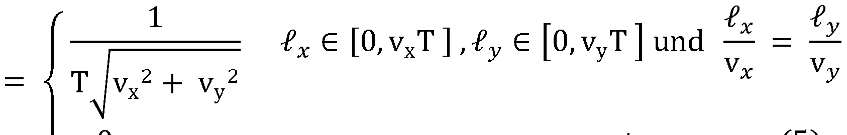
0 sonst 0 otherwise
Wiederum lässt sich die Grauwertverteilung daher als Faltung eines Faltungskerns mit der Intensitätsverteilung der nicht verschmierten Erfassungsstruktur ausdrücken: Again, the gray value distribution can therefore be expressed as a convolution of a convolution kernel with the intensity distribution of the non-blurred detection structure:
GW(x, y) = (k * I)(x, y) (6) GW (x, y) = (k * I) (x, y) (6)
Wie die Gleichung (1 ), letzte Zeile, Gleichung (6) für vereinfachte Fälle konstanter Geschwindigkeit senkrecht zur optischen Achse ausdrücken, kann die Bildwerteverteilung des Bildes der von der Kamera erfassten Erfassungsstruktur durch die Faltung eines Faltungskerns k mit der Intensitätsverteilung ausgedrückt werden. Da die As expressed in equation (1), last line, equation (6) for simplified cases of constant velocity perpendicular to the optical axis, the image value distribution of the image of the detection structure detected by the camera can be expressed by the convolution of a convolution kernel k with the intensity distribution. Because the
Intensitätsverteilung die Erfassungsstruktur in dem ursprünglichen, nicht aufgrund einer Bewegung verschmierten Zustand beschreibt und da sich der durch die Bewegung im Kamerabild verschmierte Zustand aus der Bildwerteverteilung ergibt, enthält der Intensity distribution describes the detection structure in the original, not smeared due to a motion state, and since the smeared by the movement in the camera image state results from the image value distribution contains the
Faltungskern k die Information über die Geschwindigkeit der Relativbewegung, die zu dem verschmierten Kamerabild geführt hat. Convolution kernel k the information about the speed of the relative movement that has led to the smeared camera image.
Für den Faltungskern k kann nun eine Länge definiert werden, die über die For the convolution kernel k, a length can now be defined that exceeds the
Belichtungszeit bzw. Integrationszeit und die Abbildungsgeometrie mit der Exposure time or integration time and the imaging geometry with the
Geschwindigkeit zusammenhängt. Durch die Bestimmung der Länge kann daher die Geschwindigkeit ermittelt werden. Dies setzt selbstverständlich zunächst die Ermittlung
des Faltungskerns voraus. Darauf wird noch näher eingegangen. Insbesondere kann die Erfassungsstruktur so gewählt werden, dass in dem zentralen örtlichen Bereich des Faltungskerns, der nicht den geometrischen Rand des Faltungskerns bildet, eine geometrische Teilstruktur des Faltungskerns enthalten ist und die Länge dieser Speed is related. By determining the length, therefore, the speed can be determined. Of course, this first sets the determination of the convolution kernel. This will be discussed in more detail. In particular, the detection structure can be chosen such that in the central local area of the convolution kernel, which does not form the geometric boundary of the convolution kernel, a geometric substructure of the convolution kernel is contained and the length of these
Teilstruktur die genannte Länge ist, welche der Größe und/oder Richtung der Partial structure is the length mentioned, which is the size and / or direction of
Geschwindigkeit entspricht. Speed equals.
Im Folgenden werden Beispiele für Erfassungsstrukturen beschrieben, bei denen diese Teilstruktur lediglich der Größe eines einzigen Pixels des Kamerabildes entspricht, wenn die Geschwindigkeit null ist (und wenn ansonsten keine Abbildungsfehler oder andere Einflüsse existieren, die zu einer Verschmierung der Erfassungsstruktur im Kamerabild führen). Wenn dagegen der Betrag der Geschwindigkeit nicht null ist, vergrößert sich die Teilstruktur, sodass deren Größe durch die genannte Länge beschrieben werden kann, die dem Betrag und/oder der Richtung der Geschwindigkeit entspricht. Z.B. kann die Teilstruktur der Größe von zwei einander benachbarten Pixeln des Kamerabildes entsprechen. Dies bedeutet, dass vom Beginn des Belichtungsintervalls bis zum Ende des Belichtungsintervalls eine Bewegung stattgefunden hat, die zum Versatz der In the following, examples of detection structures are described in which this substructure only corresponds to the size of a single pixel of the camera image when the speed is zero (and otherwise there are no aberrations or other influences that lead to smearing of the detection structure in the camera image). If, on the other hand, the amount of speed is not zero, the substructure increases so that its size can be described by said length corresponding to the magnitude and / or direction of the velocity. For example, For example, the substructure may correspond to the size of two adjacent pixels of the camera image. This means that from the beginning of the exposure interval until the end of the exposure interval, a movement has taken place which causes the offset of the
Erfassungsstruktur aus Sicht der Kamera um ein Kamerapixel geführt hat. Dies gilt insbesondere für den Fall konstanter Geschwindigkeit. Die Teilstruktur ergibt sich in dem zentralen Bereich aus dem Unterschied der Bildwerte (z.B. Grauwerte oder Farbwerte) zu der Umgebung der Teilstruktur im zentralen Bereich. Z.B. wird die Teilstruktur durch konstante Bildwerte in einem zusammenhängenden örtlichen Teilbereich des zentralen Bereichs des Faltungskerns definiert, während außerhalb der Teilstruktur im zentralen Bereich konstante Bildwerte auf einem anderen Bildwerteniveau als für die Teilstruktur liegen. Insbesondere kann durch geeignete Normierung der Faltung erreicht werden, dass die Bildwerte der Teilstruktur den Wert„1 " in einem möglichen Bildwerteintervall von [0, 1 ] haben, während der zentrale Bereich außerhalb der Teilstruktur durch konstante, niedrigere Bildwerte beschrieben wird, z.B. durch die Bildwerte„0". Da der Faltungskern aber insbesondere als Ortsfunktion interpretiert werden kann, deren Skalierung der Matrix des Kamerabildes entspricht, ist der zentrale Bereich des Faltungskerns insbesondere entsprechend der Unterteilung des Kamerabildes in Pixel digital strukturiert. An den Rändern der Teilstruktur des Faltungskerns kann es daher Unschärfen geben, d.h. Detection structure from the perspective of the camera has led to a camera pixel. This is especially true in the case of constant speed. The substructure results in the central area from the difference of the image values (e.g., gray values or color values) to the neighborhood of the substructure in the central area. For example, the substructure is defined by constant image values in a contiguous local subregion of the central region of the convolution kernel, while outside the substructure in the central region constant image values lie at a different image value level than for the substructure. In particular, it can be achieved by suitable normalization of the convolution that the image values of the substructure have the value "1" in a possible image value interval of [0, 1], while the central region outside the substructure is described by constant, lower image values, for example by image values "0". However, since the convolution kernel can be interpreted in particular as a spatial function whose scaling corresponds to the matrix of the camera image, the central region of the convolution kernel is digitally structured in particular according to the subdivision of the camera image into pixels. There may therefore be fuzziness at the edges of the substructure of the convolution kernel, i.
Bildwerte zwischen dem an sich konstanten Niveau der Bildwerte der Teilstruktur und dem an sich konstanten Niveau der Bildwerte außerhalb der Teilstruktur. In diesem Fall kann dennoch die Größe der Teilstruktur und damit insbesondere die genannte Länge
ermittelt werden. Verfahren zur Bestimmung der Größe der Teilstruktur sind aus der Bildverarbeitung für die Identifizierung von Objekten, die im Kamerabild unscharfe Ränder haben, bereits bekannt. In dieser Beschreibung wird daher nicht näher darauf Image values between the constant level of image values of the substructure and the constant level of image values outside the substructure. In this case, nevertheless, the size of the substructure and thus in particular the said length be determined. Methods for determining the size of the substructure are already known from image processing for the identification of objects that have blurred edges in the camera image. In this description is therefore not closer
eingegangen. received.
Wie bereits erwähnt, kann nicht nur der Betrag der Geschwindigkeit, sondern auch deren Richtungsverlauf und/oder zeitliche Änderung aus der Geometrie der Teilstruktur im zentralen Bereich des Faltungskerns ermittelt werden. Insbesondere führt eine As already mentioned, not only the magnitude of the velocity but also its directional course and / or temporal change can be determined from the geometry of the substructure in the central region of the convolution kernel. In particular, leads a
Relativbewegung mit nicht konstantem Betrag der Geschwindigkeit zu Bildwerten in der Teilstruktur des Faltungskerns, die nicht konstant sind. Die Bildwerte der den Pixeln im Kamerabild entsprechenden örtlichen Bereiche (im Folgenden der Einfachheit wegen ebenfalls Pixel genannt) können daher z.B. lediglich in einem zentralen Bereich der Teilstruktur konstant hohe oder konstant niedrige Werte haben. Es ist aber auch möglich, dass aufgrund der Art der Zunahme oder Abnahme des Geschwindigkeitsbetrages auch in einem zentralen Bereich der Teilstruktur keine konstanten Werte von Pixeln zu finden sind, d.h. es gibt keine zwei benachbarten Pixel, deren Bildwerte gleich groß sind. Relative motion with non-constant amount of velocity to image values in the sub-structure of the convolution kernel that are not constant. The image values of the local regions corresponding to the pixels in the camera image (hereinafter also referred to as pixels for the sake of simplicity) may therefore be e.g. have constant high or constant low values only in a central region of the substructure. However, it is also possible that, due to the nature of the increase or decrease in the amount of speed, even in a central region of the substructure no constant values of pixels can be found, i. there are no two adjacent pixels whose image values are the same size.
Dennoch ist die Bestimmung der Größe der Teilstruktur z.B. mit den erwähnten bereits bekannten Verfahren möglich. Aus dem Verlauf der Bildwerte entlang der Erstreckung der Teilstruktur kann außerdem Information über den zeitlichen Verlauf der Geschwindigkeit während des Belichtungszeitintervalls gewonnen werden. Dem liegt die Erkenntnis zugrunde, dass sich die Pixel der Teilstruktur des Faltungskerns wie die Pixel des Nevertheless, the determination of the size of the substructure is e.g. possible with the mentioned already known methods. From the course of the image values along the extension of the substructure, it is also possible to obtain information about the temporal course of the speed during the exposure time interval. This is based on the knowledge that the pixels of the substructure of the convolution kernel are like the pixels of the
Kamerabildes verhalten: Bei einer langsameren Bewegung erhält das jeweilige Pixel des Kamerabildes mehr Strahlungsintensität als bei langsamerer Bewegung, wenn ein entsprechender Ortsbereich mit hoher Strahlungsemission und/oder hoher Behavior of camera image: With a slower movement, the respective pixel of the camera image receives more radiation intensity than with slower movement, if a corresponding location area with high radiation emission and / or high radiation emission
Strahlungsreflektivität auf dieses Pixel abgebildet wird und ein entsprechend der Radiation reflectivity is mapped to this pixel and a corresponding to the
Bewegung nachfolgender örtlicher Bereich der Erfassungsstruktur eine geringere Movement subsequent local area of the collection structure a smaller
Strahlungsemission und/oder Strahlungsreflektivität hat. In dem vereinfachten Beispiel der obigen Gleichungen (1 ) und (5) entspricht der Erstreckung der Teilstruktur in Has radiation emission and / or radiation reflectivity. In the simplified example of the above equations (1) and (5), the extension of the partial structure in FIG
Bewegungsrichtung die Laufvariable l, auch wenn die Beispiele für den vereinfachten Fall der konstanten Geschwindigkeit beschrieben wurden. Es lässt sich aber auch für einen entsprechenden Faltungskern bei nicht konstanter Geschwindigkeit eine entsprechende Laufvariable definieren, die lediglich in dem Bereich der Erstreckung der Teilstruktur nicht verschwindende Werte hat. Insbesondere für den Fall, dass sich auch die Richtung der Bewegung während des Belichtungszeitintervalls ändert, soll hiermit nochmals klargestellt werden, dass die Länge der Teilstruktur des Faltungskerns im Allgemeinen nicht eine in
gerader Richtung zu bestimmende Länge ist, sondern eine dem durch die Bewegung zurückgelegten Weg entsprechende Länge ist. Auf ein Beispiel wird noch anhand von Fig. 9 eingegangen. Movement direction of the running variable l, even if the examples for the simplified case of constant speed have been described. However, it is also possible for a corresponding convolution kernel to define a corresponding run variable at non-constant speed, which has non-vanishing values only in the region of the extent of the substructure. In particular, in the event that the direction of the movement during the exposure time interval changes, it should again be clarified that the length of the substructure of the convolution core is generally not in straight direction is to be determined length, but a the distance traveled by the movement is corresponding length. An example will be discussed with reference to FIG. 9.
Bestimmte Klassen von Erfassungsstrukturen können auf einfache Weise hergestellt werden und ermöglichen eine besonders einfache und Rechenzeit sparende Bestimmung des Faltungskerns. Auch können die sich daraus ergebenden Teilstrukturen der Certain classes of detection structures can be easily manufactured and allow a particularly simple and time-saving determination of the convolution kernel. Also, the resulting substructures of the
Faltungskerne besonders einfach insbesondere in der oben beschriebenen Weise ausgewertet werden. Eine solche Klasse von Erfassungsstrukturen sind die sogenannten MURA (Modified Uniformly Redundant Arrays), die die Eigenschaft haben, dass sie gefaltet mit ihrer inversen Struktur einen einzigen Intensitätspeak ergeben. Dem entspricht eine mathematische Delta-Funktion. Insbesondere wird die Größe der Folding cores are particularly easy to evaluate in particular in the manner described above. One such class of collection structures are the so-called Modified Uniformly Redundant Arrays (MURA), which have the property of giving a single peak of intensity with their inverse structure folded. This corresponds to a mathematical delta function. In particular, the size of the
Strukturen des verwendeten insbesondere binären MURA so auf die Geometrie der Abbildung und Auflösung des Kamerabildes abgestimmt, dass der Intensitätspeak einem einzigen Pixel des Kamerabildes entspricht. Der entsprechende örtliche Bereich der genannten Teilstruktur im zentralen Bereich des Faltungskerns hat daher die Structures of the particular binary MURA used are matched to the geometry of the image and resolution of the camera image so that the intensity peak corresponds to a single pixel of the camera image. The corresponding local area of the mentioned substructure in the central area of the convolution kernel therefore has the
Abmessungen eines einzigen Pixels, wenn keine Verschmierung und keine Dimensions of a single pixel, if no smearing and no
Abbildungsfehler auftreten. Nicht nur für MURA wird diese Abstimmung der Geometrie der Abbildung und der Bildauflösung der Kamera bevorzugt. Aberrations occur. Not only for MURA, this coordination of the geometry of the image and the image resolution of the camera is preferred.
Allerdings lässt sich diese Bedingung abhängig von der Art der Bewegungsverfolgung beim Betrieb der Maschine nicht immer aufrechterhalten. Z.B. ändert sich die Geometrie der Abbildung mit der Entfernung der Erfassungsstruktur von der Kamera. In diesem Fall können entsprechende Korrekturen der Entfernung vorgenommen werden und/oder kann die Auswertung der Teilstruktur des Faltungskerns unter Berücksichtigung der However, depending on the type of motion tracking during operation of the machine, this condition can not always be maintained. For example, The geometry of the image changes with the distance of the detection structure from the camera. In this case, appropriate corrections of the removal can be made and / or the evaluation of the substructure of the convolution kernel taking into account the
veränderten Geometrie der Abbildung vorgenommen werden. Vorzugsweise werden daher die Geometrie der Abbildung und insbesondere die Entfernung der changed geometry of the figure to be made. Preferably, therefore, the geometry of the image and in particular the removal of
Erfassungsstruktur von der Kamera ermittelt und mit berücksichtigt. Detection structure determined by the camera and taken into account.
Alternativ kommt auch die Klasse der URA (Uniformly Redundant Arrays) für eine einfache Bestimmung und Auswertung des Faltungskerns infrage. URA ergeben mit sich selbst gefaltet einen Delta-Funktions-Peak als Ergebnis. Alternatively, the class of URA (Uniformly Redundant Arrays) comes into question for a simple determination and evaluation of the convolution kernel. URA results in a delta-function peak folded with itself as a result.
Sowohl MURA als auch URA sind insbesondere binäre Strukturen. Z.B. werden sie für die Bestimmung des Faltungskerns so gewählt, dass lediglich die auf das Intervall [0, 1 ]
normierten Bildwerte vorkommen. Ein Beispiel für ein MURA 41 ist in Fig. 8 dargestellt. Man erkennt die zum Mittelpunkt der dargestellten Fläche des MURA punktsymmetrische Struktur. Both MURA and URA are binary structures in particular. For example, they are chosen for the determination of the convolution kernel, so that only those on the interval [0, 1] normalized image values occur. An example of a MURA 41 is shown in FIG. One recognizes the point-symmetric structure to the center of the represented surface of the MURA.
Im Fall einer Erfassungsstruktur, die mit Barker-Code erstellte Teilstrukturen aufweist, hat der Faltungskern bei der Relativgeschwindigkeit 0 folgende Eigenschaften: In the case of a detection structure which has substructures created with Barker code, the convolution kernel has the following properties at the relative velocity 0:
In Verallgemeinerung der obigen Gleichungen (1 ) und (6) kann der Faltungskern dadurch ermittelt werden, dass auf die (rechts der genannten Gleichungen stehende) Faltung diejenige Operation angewendet wird, die die Intensitätsverteilung der Erfassungsstruktur eliminiert. Die Art der Operation ist daher insbesondere von der Art oder Klasse der Erfassungsstruktur abhängig. Z.B. bei MURA wird der Ausdruck, der die Faltung des Faltungskerns mit der Intensitätsverteilung der Erfassungsstruktur beschreibt, mit der inversen Erfassungsstruktur gefaltet. Es muss daher lediglich auf die erhaltene In generalization of the above equations (1) and (6), the convolution kernel can be determined by applying to the convolution (to the right of said equations) the operation that eliminates the intensity distribution of the detection structure. The type of operation is therefore dependent in particular on the type or class of the collection structure. For example, in MURA, the term describing the convolution of the convolution kernel with the intensity distribution of the detection structure is convoluted with the inverse detection structure. It must therefore only on the received
Grauwertverteilung die entsprechende Operation angewendet werden und es ergibt sich der Faltungskern k. Im Fall der URA ist dies die Faltung der Bildwerteverteilung mit der Intensitätsverteilung der Erfassungsstruktur. Es ist daher lediglich eine einzige Gray value distribution the corresponding operation are applied and it results in the convolution kernel k. In the case of the URA, this is the convolution of the image value distribution with the intensity distribution of the detection structure. It is therefore only one
Faltungsoperation erforderlich, um den Faltungskern zu bestimmen. Insbesondere kann, wie bereits erwähnt, auch bei der Auswertung des Faltungskerns ein Abbildungsfehler der Abbildung mitberücksichtigt werden. Insbesondere kann in einer vorab ausgeführten Kalibrierung des Bewegungsmesssystems für zumindest eine Relativposition und vorzugsweise für verschiedene Relativpositionen von Erfassungsstruktur und Kamera jeweils ein Faltungskern bestimmt werden, wenn keine Relativbewegung stattfindet. Convolution operation is required to determine the convolution kernel. In particular, as already mentioned, an aberration of the image can also be taken into account in the evaluation of the convolution kernel. In particular, a convolution kernel can be determined in each case in a previously executed calibration of the movement measuring system for at least one relative position and preferably for different relative positions of the detection structure and the camera, if no relative movement takes place.
Durch Auswertung des Faltungskerns kann das Ergebnis des Abbildungsfehlers ermittelt werden und beim späteren eigentlichen Betrieb des Bewegungsmesssystems By evaluating the convolution kernel, the result of the aberration can be determined and during later actual operation of the motion measuring system
berücksichtigt werden. be taken into account.
Vorzugsweise setzt sich eine Erfassungsstruktur aus mehreren aneinander grenzenden Teilbereichen zusammen, die in der Art von Kacheln eine Gesamtfläche ohne Lücken ergeben. Ein Beispiel ist die aus drei Zeilen mit je drei Teilbereichen zusammengesetzte Gesamtfläche aus neun Kacheln, die in Fig. 9 dargestellt ist. Drei der Kacheln, nämlich die Kacheln in der ersten Zeile, sind mit dem Bezugszeichen 51 bezeichnet. Der Preferably, a detection structure is composed of a plurality of adjoining subareas which, in the manner of tiles, give a total area without gaps. An example is the total area of nine tiles, which is composed of three lines with three partial areas each, which is shown in FIG. 9. Three of the tiles, namely the tiles in the first row, are designated by reference numeral 51. Of the
Teilbereich bzw. die Kachel im Zentrum der Anordnung ist mit dem Bezugszeichen 51 e bezeichnet. Jeder der Teilbereiche wird vorzugsweise durch dasselbe Muster gebildet, sodass die Muster sich aufgrund der Kachelung periodisch wiederholen. Es ist auch
möglich, durch Muster und in benachbarten Teilbereichen invertierte Muster solch periodische Strukturen als Erfassungsstruktur zu erzeugen. Die periodischen Strukturen haben den Vorteil, dass Randeffekte aufgrund der endlichen Abmessungen der Subarea or the tile in the center of the arrangement is designated by the reference numeral 51 e. Each of the partial areas is preferably formed by the same pattern, so that the patterns repeat periodically due to the tiling. It is also it is possible to generate such periodic structures as a detection structure by patterns and in adjacent subregions inverted patterns. The periodic structures have the advantage that edge effects due to the finite dimensions of the
Erfassungsstruktur bei der Bestimmung des Faltungskerns im zentralen Bereich keine oder lediglich geringe Auswirkungen haben. Abhängig von der Anzahl der zentralen, nicht den Rand der gesamten Erfassungsstruktur ergebenden Muster gibt es ein oder mehrere zentrale Bereiche, in denen jeweils die oben genannte Teilstruktur des Faltungskerns vorhanden ist, welche zur Ermittlung der Relativgeschwindigkeit ausgewertet werden kann. Mehrere solcher zentralen Bereiche können optional gleichzeitig oder nacheinander ausgewertet werden. Dies ermöglicht es insbesondere, die Genauigkeit bei der Ermittlung der Geschwindigkeit zu steigern, wenn noch Randeffekte auch im zentralen Bereich festzustellen sind und/oder wenn sonstige Effekte, wie z.B. statistische Schwankungen der Bildsignale der Kamerasensoren (Rauschen) vorkommen. Detection structure in determining the convolution kernel in the central area have little or no effect. Depending on the number of central patterns that do not result in the edge of the entire detection structure, there are one or more central areas in each of which the above-mentioned partial structure of the convolution kernel exists, which can be evaluated to determine the relative speed. Several such central areas can optionally be evaluated simultaneously or one after the other. This makes it possible, in particular, to increase the accuracy in determining the speed, if edge effects are still to be detected even in the central area, and / or if other effects, such as e.g. statistical fluctuations of the image signals of the camera sensors (noise) occur.
Die Darstellung in Fig. 9 kann als schematische Darstellung eines Faltungskerns verstanden werden, der sich durch Faltung der Bildwerteverteilung aus einem Kamerabild ergibt. Im zentralen Bereich 51 e sind zwei Teilstrukturen 53, 54 dargestellt, die nicht gleichzeitig in demselben Faltungskern zu beobachten sind, sondern die mögliche Varianten der Teilstruktur darstellen. Die Teilstruktur 53 ist z.B. eine geradlinige Struktur, die sich aus von rechts nach links in der Figur hintereinander gereihten Pixeln ergibt. Die Länge t entspricht dem Betrag der Relativgeschwindigkeit unter Berücksichtigung der Geometrie der Erfassungsstruktur und der Geometrie der Abbildung. Auch die Richtung der Bewegung mit der konstanten Geschwindigkeit kann aus der Teilstruktur 53 entnommen werden, falls dies von Interesse ist und nicht bereits durch die Eigenschaften der Maschine bekannt ist. The illustration in FIG. 9 can be understood as a schematic representation of a convolution kernel which results from convolution of the image value distribution from a camera image. In the central area 51 e, two substructures 53, 54 are shown which are not to be observed simultaneously in the same convolution kernel, but represent the possible variants of the substructure. The substructure 53 is e.g. a rectilinear structure resulting from right-to-left pixels in the figure one after another. The length t corresponds to the amount of the relative velocity taking into account the geometry of the detection structure and the geometry of the image. Also, the direction of the constant velocity motion can be extracted from the substructure 53, if that is of interest and not already known by the characteristics of the machine.
Die Teilstruktur 54 weist einen gebogenen Verlauf auf, da die Geschwindigkeit während des Belichtungszeitintervalls ihre Richtung geändert hat. Der gebogene Verlauf entspricht dem gebogenen Weg der Bewegung. Obwohl nicht dargestellt, kann die Länge der Teilstruktur 54 als Länge des gebogenen Verlaufs ermittelt werden. Dadurch wird der Betrag der Geschwindigkeit bzw. der Mittelwert des Betrages der Geschwindigkeit ermittelt. Der gebogene Verlauf enthält die Information über die Bewegungsrichtung. The substructure 54 has a curved course since the speed has changed direction during the exposure time interval. The curved course corresponds to the curved path of the movement. Although not shown, the length of the substructure 54 may be determined as the length of the curved path. Thereby, the amount of the speed or the mean value of the amount of the speed is determined. The curved course contains the information about the direction of movement.
Wenn sich die Erfassungsstruktur in einer Ebene erstreckt, die nicht senkrecht zur Abbildung der optischen Achse verläuft, werden die Abbildungen der einzelnen Kacheln,
die an sich gleiche Muster aufweisen, als unterschiedliche Muster im Kamerabild abgebildet. Dies kann jedoch insbesondere unter Verwendung von Informationen über die Neigung der Ebene relativ zur optischen Achse vor, während und/oder nach der If the detection structure extends in a plane that is not perpendicular to the optical axis, the images of the individual tiles, have the same per se, as different patterns shown in the camera image. However, this can be done in particular by using information about the inclination of the plane relative to the optical axis before, during and / or after
Auswertung des Kamerabildes berücksichtigt werden. Evaluation of the camera image are taken into account.
Fig. 10 zeigt zeitliche Verläufe der Strahlungsflussdichte Φ auf ein Sensorelement der Kamera, welches ein Kamerabild-Pixel erzeugt, wobei die Verläufe für drei FIG. 10 shows temporal profiles of the radiation flux density Φ on a sensor element of the camera, which generates a camera image pixel, the progressions for three
unterschiedliche Bewegungen dargestellt sind. Das Kamerapixel enthält die integrierte Information über die durch das Sensorelement empfangene Strahlung über das different movements are shown. The camera pixel contains the integrated information about the radiation received by the sensor element via the
Belichtungszeitintervall, welches zum Zeitpunkt t1 beginnt und zum Zeitpunkt t2 endet. In allen drei dargestellten Fällen beginnt die Bewegung zum Zeitpunkt t1 und endet zum Zeitpunkt t2. Bis zum Zeitpunkt t1 , also bis zum Beginn des Belichtungszeitraums, empfängt das Sensorelement Strahlung bei einer maximalen Strahlungsflussdichte. Durch die Bewegung nimmt die Strahlungsflussdichte jedoch bis zum Ende des Exposure time interval, which begins at time t1 and ends at time t2. In all three cases shown, the movement begins at time t1 and ends at time t2. Until the time t1, ie until the beginning of the exposure period, the sensor element receives radiation at a maximum radiation flux density. However, by the movement, the radiation flux density decreases until the end of the
Belichtungszeitintervalls zum Zeitpunkt t2 auf 0 ab. Eine erste Bewegung findet mit konstanter Geschwindigkeit während des Belichtungszeitintervalls statt, (durchgezogene Linie des Strahlungsflussdichteverlaufs). Eine zweite Bewegung verläuft im ersten Teil des Belichtungszeitintervalls mit konstanter Geschwindigkeit, stoppt dann und wird gegen Ende des Belichtungszeitintervalls wieder mit konstanter Geschwindigkeit in die gleiche Richtung wie zuvor fortgesetzt (gestrichelte Linie des Strahlungsflussdichteverlaufs). Ferner ist der Strahlungsflussdichteverlauf für eine dritte Bewegung ähnlich der zweiten Bewegung dargestellt, wobei jedoch der Zeitraum der Unterbrechung der Bewegung in der Mitte des Belichtungszeitintervalls größer ist und daher auch der Betrag der Exposure time interval at time t2 to 0 from. A first movement takes place at a constant speed during the exposure time interval (solid line of the radiation flux density trajectory). A second movement proceeds in the first part of the exposure time interval at a constant speed, then stops and is again at constant speed in the same direction as before (end of the exposure time interval) (dashed line of the radiant flux density trace). Furthermore, the Radiantflussdichteverlauf is shown for a third movement similar to the second movement, but the period of interruption of movement in the middle of the exposure time interval is greater, and therefore the amount of
Geschwindigkeit zu Beginn und am Ende des Belichtungszeitintervalls größer ist. Dieser dritte Verlauf ist durch eine gepunktete Linie dargestellt. Speed is greater at the beginning and at the end of the exposure time interval. This third course is represented by a dotted line.
In allen drei Fällen empfängt das Sensorelement die gleiche Strahlungsmenge. Dies folgt aus der Darstellung in Fig. 10 durch Integration der Strahlungsflussdichteverläufe über das Zeitintervall von t1 bis t2. Alle drei Flächen unter den Strahlungsflussdichteverläufen sind gleich groß. Daher kann das Sensorelement und die von ihm gelieferte Information nicht dazu genutzt werden, den Bewegungsverlauf während des Belichtungszeitintervalls zu identifizieren. Dies bezieht sich allerdings lediglich auf den dargestellten idealen Verlauf der Bewegungen, die genau zum Zeitpunkt t1 beginnen und genau zum Zeitpunkt t2 enden. Dies bezieht sich auch auf die Betrachtung lediglich eines einzigen Pixels. Wie bereits ausgeführt wurde, kann anhand der Betrachtung mehrerer Pixel Information über
den zeitlichen Verlauf während des Integrationszeitintervalls gewonnen werden. Im Folgenden wird jedoch beschrieben, dass auch bereits die Betrachtung eines einzigen Kamerapixels zu einer Möglichkeit führt, den Informationsgehalt über den Verlauf der Bewegung im Kamerabild insgesamt zu erhöhen. In all three cases, the sensor element receives the same amount of radiation. This follows from the illustration in FIG. 10 by integrating the radiation flux density courses over the time interval from t1 to t2. All three surfaces under the Strahlungsflussdichteverläufen are the same size. Therefore, the sensor element and the information provided by it can not be used to identify the course of the movement during the exposure time interval. However, this only relates to the illustrated ideal course of the movements, which start exactly at time t1 and end precisely at time t2. This also applies to the consideration of only a single pixel. As already stated, by considering several pixels, information about the time course during the integration time interval are obtained. However, it is described below that even the observation of a single camera pixel leads to a possibility to increase the information content overall over the course of the movement in the camera image.
Fig. 1 1 zeigt die über ein Belichtungszeitintervall eines Sensorelements integrierte Strahlungsflussdichte J (|)(t)dt. Jeweils zum Ende eines Integrationszeitintervalls zu den Zeitpunkten t1 , t2 und t3 ist durch ein kleines dunkles Rechteck der Integrationswert dargestellt, den das Sensorelement liefert. Dabei findet eine Bewegung statt, die dem mit einer durchgezogenen Linie in Fig. 10 dargestellten Strahlungsflussdichteverlauf entspricht, d.h. die Geschwindigkeit ist während des Integrationszeitintervalls zwischen den Zeitpunkten t1 und t2 konstant und davor sowie danach null. Daher liegt der FIG. 11 shows the radiation flux density J (|) (t) dt integrated over an exposure time interval of a sensor element. At the end of an integration time interval at the times t1, t2 and t3, the integration value provided by the sensor element is represented by a small dark rectangle. In this case, a movement takes place, which corresponds to the radiation flux density curve shown by a solid line in Fig. 10, i. the speed is constant during the integration time interval between times t1 and t2 and before and after zero. Therefore lies the
Integrationswert zum Zeitpunkt t1 bei dem maximal möglichen Wert. Zum Zeitpunkt t2 liegt der Integrationswert bei 50 % des maximalen Wertes und zum Zeitpunkt t3 (also ein vollständiges Integrationszeitintervall nach dem Ende der Bewegung) liegt der Integration value at time t1 at the maximum possible value. At time t2, the integration value is 50% of the maximum value, and at time t3 (ie, a complete integration time interval after the end of the movement) is
Integrationswert bei null. Integration value at zero.
Fig. 12 zeigt die Integrationswerte bei einer gegenüber Fig. 1 1 modifizierten Situation. Die Modifikation besteht darin, dass zwar nicht die Dauer der Integrationszeitintervalle geändert wurde, jedoch die Zeitpunkte des Beginns und des Endes des jeweiligen Integrationszeitintervalls. Dieselben Resultate würde man erhalten, wenn sich Beginn und Ende des Zeitintervalls der Bewegung mit konstanter Geschwindigkeit verschoben hätten. FIG. 12 shows the integration values for a situation modified relative to FIG. 11. The modification is that, although not the duration of the integration time intervals has been changed, but the times of the beginning and the end of the respective integration time interval. The same results would be obtained if the beginning and end of the time interval of the movement had shifted at a constant speed.
Im Folgenden wird auf die Situation eingegangen, dass wie bei Fig. 1 1 der zeitliche Verlauf der Strahlungsflussdichte, die auf das Sensorelement einfällt, durch die durchgezogene Linie in Fig. 10 dargestellt ist. Das Belichtungszeitintervall beginnt jedoch immer um ein halbes Zeitintervall versetzt gegenüber der anhand von Fig. 1 1 In the following, the situation is discussed that, as in FIG. 11, the time profile of the radiation flux density incident on the sensor element is shown by the solid line in FIG. However, the exposure time interval always starts offset by half a time interval compared to that of FIG. 11
beschriebenen Situation. Daher liegt der Integrationswert bei der Darstellung in Fig. 12 zum Zeitpunkt eines halben Integrationszeitintervalls vor dem Zeitpunkt t1 noch auf dem Maximalwert. Am Ende des nächsten Integrationszeitintervalls, genau in der Mitte zwischen den Zeitpunkten t1 und t2, liegt der Integrationswert aber lediglich um ein Viertel unter dem Maximalwert am Ende des nächsten Integrationszeitintervalls. In der Mitte der Zeitpunkte t2 und t3 liegt der Integrationswert bei einem Viertel des Maximalwertes. Erst am Ende des folgenden Integrationszeitintervalls nach dem Zeitpunkt t3 liegt der described situation. Therefore, the integration value in the illustration in FIG. 12 at the time of a half integration time interval before time t1 is still at the maximum value. However, at the end of the next integration time interval, exactly midway between times t1 and t2, the integration value is only one-quarter below the maximum value at the end of the next integration time interval. In the middle of the times t2 and t3, the integration value is one quarter of the maximum value. Only at the end of the following integration time interval after the time t3 is the
Integrationswert bei null, da die Bewegung erst zum Zeitpunkt t2 endet und erst das nach
dem Zeitpunkt t3 beendete Integrationszeitintervall ein vollständiges Integration value at zero, since the movement ends only at time t2 and only after The integration time interval completed at time t3 is complete
Integrationszeitintervall ist, in dem keine Strahlung empfangen wurde. Integration time interval is where no radiation was received.
Wenn dagegen die Bewegung stattfindet, die in Fig. 10 dem Verlauf der In contrast, when the movement takes place, the in Fig. 10 the course of
Strahlungsflussdichte entspricht, der mit einer gestrichelten Linie dargestellt ist, werden zwischen den Zeitpunkten t1 und t3 zwei andere Integrationswerte erhalten, die durch nicht dunkel ausgefüllte Rechtecke in Fig. 12 dargestellt sind. Dies liegt daran, dass in dem Integrationszeitintervall, das zwischen den Zeitpunkten t1 und t2 endet, die Corresponds to radiation flux density, which is shown with a dashed line, two other integration values are obtained between the times t1 and t3, which are represented by not dark filled rectangles in Fig. 12. This is because in the integration time interval ending between times t1 and t2, the
Strahlungsflussdichte schneller abgefallen ist, jedoch in dem Integrationsintervall, das zwischen den Zeitpunkten t2 und t3 endet, die Strahlungsflussdichte noch nicht so schnell abgefallen ist wie in dem anderen dargestellten Fall mit der durchgezogenen Linie in Fig. 10. Radiation flux density has dropped faster, but in the integration interval ending between times t2 and t3, the radiation flux density has not yet dropped as fast as in the other illustrated case with the solid line in FIG.
Daraus kann die Schlussfolgerung gezogen werden, dass die Lage des From this it can be concluded that the situation of the
Integrationszeitintervalls einen Einfluss darauf hat, welche Integrationswerte und damit Bildwerte die einzelnen Sensorelemente der Kameramatrix liefern. Integration time interval has an influence on which integration values and thus image values provide the individual sensor elements of the camera matrix.
Diese Erkenntnis kann in unterschiedlicher Weise genutzt werden, um den This insight can be used in different ways to the
Informationsgehalt über den zeitlichen Verlauf der Bewegung zu erhöhen und durch Auswertung des Kamerabildes oder einer Mehrzahl von Kamerabildern Information über den zeitlichen Verlauf der Bewegung zu ermitteln. Dies ermöglicht insbesondere die einfache Bestimmung von Betrag und Richtung der Geschwindigkeit, das heißt des Geschwindigkeitsvektors. In allen Fällen wird Information durch zumindest eine Kamera erfasst, die über unterschiedliche Integrationszeiträume integrierte Strahlungsmengen enthält. Eine einzige Kamera kann bereits ein Kamerabild liefern, dessen Pixel To increase information content over the time course of the movement and to determine information about the time course of the movement by evaluating the camera image or a plurality of camera images. In particular, this makes it possible to easily determine the magnitude and direction of the velocity, that is to say the velocity vector. In all cases, information is detected by at least one camera that contains integrated amounts of radiation over different integration periods. A single camera can already provide a camera image whose pixels
Integrationswerte von zeitversetzten, aber z.B. gleich langen Integrationszeiträumen sind. Solche Kameras werden auch als sogenannte Kameras mit rollendem Verschluss bezeichnet (englisch: rolling shutter cameras). Bei Verwendung einer einzigen Kamera mit zeitlich versetzten Integrationszeiträumen wird bevorzugt, dass die insgesamt von dem Kamerabild erfasste Erfassungsstruktur in verschiedenen Teilbereichen redundante Information enthält. Z.B. erfasst die Kamera eine erste Hälfte der Erfassungsstruktur mit der oberen Hälfte des Kamerabildes und die zweite Hälfte der Erfassungsstruktur mit der unteren Hälfte des Kamerabildes. Wenn sich die Integrationszeiträume der oberen Hälfte und der unteren Hälfte des Kamerabildes unterscheiden und sich in der ersten Hälfte und der zweiten Hälfte der Erfassungsstruktur redundante Strukturinformation befindet, wird
der Informationsgehalt in dem Kamerabild erhöht. Alternativ oder zusätzlich ist es möglich, eine Mehrzahl von Kameras zu verwenden, deren Integrationszeiträume sich unterscheiden. Integration values of time-shifted, but for example equal length integration periods are. Such cameras are also referred to as so-called rolling shutter cameras (English: rolling shutter cameras). When using a single camera with temporally offset integration periods, it is preferred that the detection structure captured in total by the camera image contains redundant information in different subareas. For example, the camera detects a first half of the detection structure with the upper half of the camera image and the second half of the detection structure with the lower half of the camera image. If the integration periods of the upper half and the lower half of the camera image are different and there is redundant structure information in the first half and the second half of the detection structure, then the information content in the camera image increases. Alternatively or additionally, it is possible to use a plurality of cameras whose integration periods differ.
In allen Fällen können sich die Integrationszeiträume nicht oder nicht lediglich dadurch unterscheiden, dass sie zeitlich gegeneinander versetzt sind. Vielmehr kann sich (auch) die Dauer bzw. Länge der Integrationszeiträume unterscheiden. In all cases, the integration periods can not or not only differ in that they are temporally offset from each other. Rather, the duration or length of the integration periods may (also) differ.
Eine weitere Überlegung verdeutlicht, dass aus einem oder mehreren Kamerabildern mit Bildinformation, die aus unterschiedlichen Integrationszeiträumen der Integration von Strahlung stammt, die Geschwindigkeit der Bewegung und/oder der zeitliche Verlauf der Bewegung ermittelt werden kann. Allgemein formuliert kann daher das Kamerabild Pixel aufweisen, deren Bildwerte jeweils einer über ein Belichtungszeitintervall integrierten Strahlungsmenge entsprechen, wobei sich die Belichtungszeitintervalle verschiedener Pixel des Kamerabildes voneinander unterscheiden und wobei unter Berücksichtigung von Informationen über die unterschiedlichen Belichtungszeitintervalle die A further consideration makes it clear that the speed of the movement and / or the time course of the movement can be determined from one or more camera images with image information which originates from different integration periods of the integration of radiation. In general terms, therefore, the camera image may comprise pixels whose image values each correspond to an amount of radiation integrated over an exposure time interval, the exposure time intervals of different pixels of the camera image differing from each other and taking into account information about the different exposure time intervals
Geschwindigkeit der Relativbewegung und/oder Informationen über einen zeitlichen Verlauf der Bewegung ermittelt wird/werden. Bereits aus einem einzigen Kamerabild mit Bildinformation, die aus unterschiedlichen Integrationszeiträumen stammt, kann/können die Orientierung und/oder der zeitliche Verlauf der Bewegung ermittelt werden. Speed of relative movement and / or information about a time course of the movement is / are determined. Already from a single camera image with image information, which comes from different integration periods, the orientation and / or the time course of the movement can / can be determined.
Wird zum Beispiel eine linienförmige Struktur, die sich quer zur Längserstreckung der Linie bewegt, mit Pixeln aus gegeneinander versetzten Integrationszeiträumen erfasst, ergibt sich ein Versatz der Linie. Nimmt beispielsweise ein erstes Pixel den einen Endabschnitt der Linie über ein erstes Zeitintervall auf, nimmt ein zweites Pixel den mittleren Abschnitt der Linie über ein zweites, gegen das erste Zeitintervall um ein Drittel versetztes Zeitintervall auf und nimmt ein drittes Pixel den anderen Endabschnitt der Linie zu einem dritten, um zwei Drittel gegen das erste Zeitintervall versetztes Zeitintervall auf, ergeben sich in dem gesamten Kamerabild drei Linien, die jeweils einem Drittel den drei Abschnitten der ursprünglichen Linie entsprechen. Unter Berücksichtigung des If, for example, a line-shaped structure that moves transversely to the longitudinal extent of the line is detected with pixels from mutually offset integration periods, this results in an offset of the line. For example, if a first pixel occupies the one end portion of the line over a first time interval, a second pixel occupies the middle portion of the line for a second time interval offset from the first time interval by one-third and adopts a third pixel to the other end portion of the line A third time interval offset by two thirds from the first time interval results in three lines in the entire camera image, each corresponding to one third of the three sections of the original line. Taking into account the
Zeitversatzes der Zeitintervalle kann die Geschwindigkeit berechnet werden und/oder der zeitliche Verlauf der Geschwindigkeit und/oder die Orientierung der Bewegung ermittelt werden. Je nach Orientierung, unterscheidet sich die Anordnung der drei Linien im Kamerabild.
Daher wird vorzugsweise die Erfassungsstruktur so ausgelegt, dass sie Information (zum Beispiel Kantenverläufe oder eine bekannte Binärstruktur) enthält, die bei Time offset of the time intervals, the speed can be calculated and / or the time course of the speed and / or the orientation of the movement can be determined. Depending on the orientation, the arrangement of the three lines differs in the camera image. Therefore, it is preferable that the detection structure be designed to contain information (for example, edge characteristics or a known binary structure) that is useful
unterschiedlichen Zeitintervallen der Strahlungsintegration zur Ermittlung der different time intervals of the radiation integration to determine the
Geschwindigkeit genutzt werden kann. Z. B. kann durch entsprechende Wahl der Objektinhalte der Erfassungsstruktur erreicht werden, dass die Verschmierung im Speed can be used. For example, it can be achieved by appropriate selection of the object contents of the detection structure that the smearing in the
Kamerabild errechnet werden kann, um anschließend aus dem Versatz in den Camera image can be calculated to subsequently from the offset in the
Teilbereichen (z. B. Zeilen) des Bildes die Geschwindigkeit im zu errechnen. Subareas (eg lines) of the image to calculate the speed in.
Insbesondere ist eine an sich bekannte Digitalkamera verwendbar, die eine Sensormatrix mit zumindest einer Zeile von Sensorelementen hat, deren Integrationswerte In particular, a digital camera known per se can be used which has a sensor matrix with at least one row of sensor elements whose integration values
nacheinander in der Reihenfolge der Sensorelemente entlang der Zeile aus gelesen werden und als Bildwerten der Pixel des Kamerabildes genutzt werden. Aus der Dauer für das Auslesen der Bildwerte einer Zeile ergibt sich die Zeilengeschwindigkeit. Im Fall einer zweidimensionalen Sensormatrix mit in Zeilen und Spalten angeordneten successively read in the order of the sensor elements along the line and be used as image values of the pixels of the camera image. The duration for reading out the image values of a line results in the line speed. In the case of a two-dimensional sensor matrix arranged in rows and columns
Sensorelementen können die einzelnen Zeilen (oder alternativ die einzelnen Spalten) nacheinander mit der Zeilengeschwindigkeit ausgelesen werden. Insbesondere kann daher aus dem örtlichen Versatz (d.h. einer Positionsverschiebung) der durch Sensor elements, the individual rows (or alternatively the individual columns) can be read out successively with the line speed. In particular, therefore, from the local offset (i.e., a positional shift) of FIG
verschiedene Zeilen oder verschiedene Spalten eines zweidimensionalen Kamerabildes erfassten Kamerabildes der Erfassungsstruktur die Geschwindigkeit ermittelt werden. different lines or different columns of a two-dimensional camera image captured camera image of the detection structure, the speed can be determined.
Ein Bild einer Erfassungsstruktur, das von einer einzelnen Zeile von Sensorelementen, aufgenommen wird, kann zunächst nicht von der Geschwindigkeit Null unterschieden werden, wenn sich die Erfassungsstruktur mit der Zeilengeschwindigkeit der Kamera bewegt. Allerdings führt die Bewegung des Objektes (der Erfassungsstruktur) anders als bei einem nicht bewegten Objekt zu einer Verschmierung, abhängig von Geschwindigkeit und Belichtungszeit der einzelnen Sensorelemente. Wie andernorts in dieser An image of a detection structure taken by a single row of sensor elements can not initially be distinguished from zero velocity as the detection structure moves at the line speed of the camera. However, unlike a non-moving object, the movement of the object (the detection structure) causes smearing, depending on the speed and exposure time of the individual sensor elements. Like elsewhere in this
Beschreibung beschrieben kann daher die Geschwindigkeit anhand der Verschmierung bzw. Veränderung des Bildes der Erfassungsstruktur gegenüber der nicht bewegten Erfassungsstruktur ermittelt werden. Described description, therefore, the speed can be determined based on the smearing or changing the image of the detection structure relative to the non-moving detection structure.
Allgemeiner formuliert wird es daher bevorzugt, die Kenntnis über die unterschiedlichen Integrationszeitintervalle mit der Geschwindigkeitsmessung unter Berücksichtigung der Informationen über die tatsächliche Erscheinung der Erfassungsstruktur zu kombinieren. Insbesondere wird die Erfassungsstruktur daher so konzipiert und hergestellt, dass sie sowohl anhand von Verschmierungen als auch durch Effekte der unterschiedlichen
Integrationszeitintervalle eine Ermittlung der Relativbewegung von Kamera und More generally, it is therefore preferable to combine the knowledge about the different integration time intervals with the speed measurement taking into account the information about the actual appearance of the detection structure. In particular, the detection structure is therefore designed and manufactured so that it can be determined both by smearing and by effects of the different Integration time intervals a determination of the relative movement of camera and
Erfassungsstruktur ermöglichen. Enable collection structure.
Vorteilhaft kann eine Mehrzahl von Kameras, zumindest zwei Kameras, mit insbesondere gleichgroßer Anzahl von Zeilen und Spalten der Sensorelemente und gleicher Advantageously, a plurality of cameras, at least two cameras, in particular with the same number of rows and columns of the sensor elements and the same
Zeilengeschwindigkeit verwendet werden. Dabei unterscheidet sich aber bei den verschiedenen Kameras die Reihenfolge, in der die von den Sensorelementen über die individuellen Integrationszeitintervalle aufintegrierten Strahlungsmengen als Bildwerte ausgelesen werden. Zum Beispiel bei einem Auslesen der Bildwerte zweier Kameras kann das Auslesen bei der ersten Kamera mit dem Sensorelement in der ersten Zeile und der ersten Spalte beginnen (oder bei Zeilenkameras mit dem ersten Sensorelement) und kann das Auslesen bei der zweiten Kamera mit dem Sensorelement in der letzten Zeile und der letzten Spalte beginnen (oder bei Zeilenkameras mit dem letzten Sensorelement der Zeile). Handelsübliche Kameras lesen die Bildwerte zeilenweise gleichzeitig aus. In diesem Fall kann das Auslesen bei der ersten Kamera zum Beispiel mit der ersten Zeile und bei der zweiten Kamera mit der letzten Zeile beginnen. Bei einer anderen Line speed can be used. In the case of the different cameras, however, the sequence in which the radiation quantities integrated in by the sensor elements over the individual integration time intervals are read out as image values differs. For example, when reading out the image values of two cameras, the readout in the first camera can begin with the sensor element in the first row and the first column (or with line scan cameras with the first sensor element) and can read out in the second camera with the sensor element in the first camera Last line and last column begin (or on line scan cameras with the last sensor element of the line). Commercially available cameras read the image values line by line at the same time. In this case, for the first camera, for example, the reading may begin with the first line and the second line with the last line. With another
Ausgestaltung kann das Auslesen im zentralen Bereich der Matrix (z. B. bezüglich der Zeilen und/oder der zweidimensionalen Matrix) gleichzeitig bei beiden oder allen Kameras beginnen, wobei jedoch die Sensorelemente in umgekehrter Reihenfolge ausgelesen werden. Bei zeilenweise gleichzeitigem Auslesen beginnt das Auslesen bei der ersten Kamera zum Beispiel mit der letzten Zeile der ersten Hälfte der Zeilen und bei der zweiten Kamera mit der ersten Zeile der zweiten Hälfte der Zeilen. Das Auslesen findet insbesondere mit gleicher Zeilengeschwindigkeit und bei zweidimensionalen Matrizen Zeile für Zeile nacheinander statt. Dies kann allgemein als gekreuztes Auslesen bezeichnet werden. Dabei sind die Matrizen der Sensorelemente der verschiedenen Kameras insbesondere in gleicher Weise auf die Erfassungsstruktur ausgerichtet, d.h. derselbe oder ungefähr derselbe Bereich der Erfassungsstruktur wird durch das erste Sensorelement der jeweiligen Kamera erfasst. Das gekreuzigte auslesen kann zum Beispiel dadurch auf einfache Weise erreicht werden, dass zwei gleichartige Kameras mit rollierendem Auslesen relativ zueinander mit ihren optischen Achsen um 180 ° gedreht auf die Erfassungsstruktur ausgerichtet werden. Zum Beispiel können die Kameras zunächst in gleicher Weise auf die Erfassungsstruktur ausgerichtet werden und dann eine der Kameras um 180 ° um Ihre optische Achse gedreht werden.
Dieses spezielle Beispiel verdeutlicht, dass allein durch Berücksichtigung des örtlichen Versatzes der gleichzeitig aufgenommenen Kamerabilder der beiden Kameras In the embodiment, read-out in the central region of the matrix (for example with respect to the lines and / or the two-dimensional matrix) can start simultaneously at both or all of the cameras, but the sensor elements are read out in the reverse order. In the case of line-by-line simultaneous read-out, reading starts with the first camera, for example with the last line of the first half of the lines, and with the second camera with the first line of the second half of the lines. The readout takes place in particular at the same line speed and in two-dimensional arrays line by line instead of one after the other. This can generally be referred to as crossed readout. In this case, the matrices of the sensor elements of the different cameras are aligned in particular in the same way on the detection structure, ie, the same or approximately the same area of the detection structure is detected by the first sensor element of the respective camera. The crucified reading can be achieved, for example, in a simple manner by aligning two similar cameras with rolling read-out relative to one another with their optical axes turned by 180 ° onto the detection structure. For example, the cameras may first be similarly aligned with the detection structure, and then one of the cameras rotated 180 degrees about its optical axis. This specific example makes it clear that by taking into account the local offset of the simultaneously recorded camera images of the two cameras
Information über die Relativbewegung aufgenommen wird, die vorzugsweise zur Bestimmung der Geschwindigkeit und/oder zumindest einer anderen klimatischen Größe der Bewegung genutzt wird. Information about the relative movement is taken, which is preferably used to determine the speed and / or at least one other climatic magnitude of the movement.
Insbesondere bei Verwendung von mehr als zwei Kameras wird bevorzugt, dass die Reihenfolge des Auslesens der Sensorelemente sich bei allen Kameras unterscheidet und/oder dass einander entsprechende, denselben Bereich der Erfassungsstruktur erfassende Sensorelemente bei den verschiedenen Kameras zeitversetzt aus gelesen werden. In particular when more than two cameras are used, it is preferred that the order of reading out the sensor elements differs for all cameras and / or that sensor elements corresponding to one another and detecting the same region of the detection structure are read out of the different cameras in a time-shifted manner.
Durch die unterschiedliche Reihenfolge des Auslesens wird insbesondere bei mehr als zwei Kameras eine Homogenisierung des Auflösungsvermögens des Kameraensembles bei der Erfassung der Bewegung in unterschiedlichen Raumrichtungen erreicht, so dass in die Objektgeschwindigkeiten in den unterschiedlichen Raumrichtungen mit annähernd gleicher Genauigkeit gemessen werden können. Due to the different order of readout, a homogenization of the resolving power of the camera ensemble is achieved when detecting the movement in different spatial directions, in particular in the case of more than two cameras, so that the object speeds in the different spatial directions can be measured with approximately the same accuracy.
Vorteilhaft ist es, die Erfassungsstruktur derart herzustellen, dass sie keine periodischen Strukturelemente enthält, welche im geplanten Objektgeschwindigkeitsspektrum zu nicht eindeutigen Bildern führen, wie dies z.B. bei einem scheinbaren Rückwärtsdrehen eines vorwärts drehenden Speichenrades mit einer Filmkamera bei entsprechenden wiederholt Frequenzen der Bildaufnahme der Fall ist. It is advantageous to produce the detection structure in such a way that it does not contain any periodic structural elements which lead to ambiguous images in the planned object velocity spectrum, as described e.g. in an apparent reverse rotation of a forward-rotating spoked wheel with a film camera at corresponding repeated frequencies of the image recording is the case.
Der zeitversetzte Betrieb mehrerer Kameras ist auch eine Möglichkeit, die Auflösung der Geschwindigkeitsmessung zu steigern. Alternativ oder zusätzlich ermöglicht dieser zeitversetzte Betrieb eine Bewegungsmessung mit Ermittlung von Tiefeninformation. E The time-shifted operation of several cameras is also a way to increase the resolution of the speed measurement. Alternatively or additionally, this time-shifted operation enables a motion measurement with determination of depth information. e
Eine weitere vorteilhafte Möglichkeit zur Vermeidung des Problems, dass es bei bestimmten Kombinationen aus Geschwindigkeiten und Objektinhalten zu nicht umkehrbaren oder uneindeutigen Ergebnissen kommen kann, besteht in der Verwendung von Rolling-Shutter-Ausleseverfahren bei mehr als einer Kamera, in denen nicht nur eine Ausleserichtung vorkommt. Beispiele dazu wurden bereits genannt. Insbesondere kann auch die Auslesereihenfolge beim Auslesen der Bildwerte jeweils derselben Kamera insbesondere nach dem auslesen eines vollständigen Kamerabildes geändert werden.
Alternativ oder zusätzlich können auch Ausleseverfahren angewendet werden, die rollierendes Auslesen zur Bildung eines Kamerabildes bei zumindest einer Kamera mit gleichzeitigem Auslesen aller Sensorelemente zur Bildung eines Kamerabildes bei zumindest einer anderen Kamera kombinieren, bei denen sich die Auslesefrequenzen bei den verschiedenen Kameras des Ensembles unterscheiden. Dadurch kann gewährleistet werden, dass eindeutige Bildinformationen aufgenommen werden. A further advantageous way of avoiding the problem that irreversible or ambiguous results may occur with certain combinations of speeds and object contents is the use of rolling shutter readout methods in more than one camera in which not only one readout direction occurs , Examples have already been mentioned. In particular, the reading sequence when reading out the image values of the same camera, in particular after reading out a complete camera image, can also be changed. Alternatively or additionally, readout methods can also be used which combine rolling readout to form a camera image in at least one camera with simultaneous readout of all sensor elements to form a camera image in at least one other camera in which the readout frequencies in the different cameras of the ensemble differ. This can ensure that unique image information is recorded.
Alternativ oder zusätzlich kann die Erfassungsstruktur im Laufe der Zeit verändert werden, zum Beispiel unter Verwendung zumindest eines Displays, und/oder verschiedene Strukturelemente durch unterschiedliche Farben (durch Reflexion und/oder Emission von Strahlung) zu realisieren. In dem letztgenannten Fall werden farbempfindliche Kameras verwendet. Dies beruht jedoch auf demselben Grundansatz wie bei der Verwendung von Kameras oder Kamerabereichen mit unterschiedlichen Integrationszeitintervallen. Alternatively or additionally, the detection structure can be changed over time, for example by using at least one display, and / or to realize different structural elements by different colors (by reflection and / or emission of radiation). In the latter case, color sensitive cameras are used. However, this is based on the same basic approach as when using cameras or camera areas with different integration time intervals.
Zeitliche Variabilität der Erfassungsstruktur kann beispielsweise dadurch erreicht werden, dass die Erfassungsstruktur zumindest ein Display aufweist, welches eine durch das Display dargestellte Grauwertverteilung im Laufe der Zeit verändert. Dabei kann der Zustand der Grauwertverteilung abhängig von zumindest einem Parameter der Maschine gewählt werden. Auf diese Weise kann (im Frequenzraum) der Zustand der Temporal variability of the detection structure can be achieved, for example, by virtue of the fact that the detection structure has at least one display which changes a gray scale distribution represented by the display over time. In this case, the state of the gray value distribution can be selected as a function of at least one parameter of the machine. In this way (in frequency space) the state of the
Erfassungsstruktur (insbesondere der Frequenzinhalt der Erfassungsstruktur) an die momentane (zum Beispiel von der Antriebssteuerung beabsichtigte) zu messende Detection structure (in particular the frequency content of the detection structure) to the current (for example, intended by the drive control) to be measured
Geschwindigkeit angepasst werden. Speed can be adjusted.
In einer Ausführungsform kann die kontinuierliche Grauwertverteilung In one embodiment, the continuous gray scale distribution
betriebsparameterabhängig auf zumindest einem selbstleuchtenden Display dargestellt werden, wobei das Pixelrastern des Displays insbesondere klein im Vergleich zur Depending on the operating parameters, they can be displayed on at least one self-illuminating display, the pixel raster of the display being, in particular, small in comparison to
Auflösung der Abbildung auf das Kamerabild ist. Insbesondere kann die Information über die gemessene Geschwindigkeit des beweglichen Teils der Maschine und optional auch des aus dem Kamerabild ermittelten Ortes verwendet werden, um unter Berücksichtigung der geplanten Trajektorie der Bewegung mit einem optionalen Sicherheitszuschlag für zu erwartende Bahnabweichungen vor ab den auszuwertenden Teilbereich des Resolution of the image on the camera image is. In particular, the information about the measured speed of the movable part of the machine and optionally also of the location determined from the camera image can be used, taking into account the planned trajectory of the movement with an optional safety margin for expected path deviations from the sub-range of the
Kamerabildes festzulegen. Auf diese Weise kann aus Einzelbildern die Regelgröße Istgeschwindigkeit und optional auch Istposition für die Regelung der Bewegung des beweglichen Teils erzeugt werden.
Die aus der Geschwindigkeitsmessung gewonnene Information kann insbesondere auch dazu verwendet werden, die Verschmierungen der Erfassungsstruktur im Kamerabild an zu korrigieren. Damit kann die Auflösung und/oder die Genauigkeit für eine Bestimmung der Position des beweglichen Teils durch Auswertung des Kamerabildes gesteigert werden. Camera image. In this way, the controlled variable actual speed and optionally also actual position for the regulation of the movement of the movable part can be generated from individual images. The information obtained from the speed measurement can in particular also be used to correct the smearing of the detection structure in the camera image. Thus, the resolution and / or the accuracy for a determination of the position of the movable part can be increased by evaluating the camera image.
Zur Stabilisierung von Messungen von Orts- und Geschwindigkeitskomponenten in Richtung der optischen Ache oder ungefähr in Richtung der optischen Achse der Abbildung können stereoskopische Bilder verwendet werden. Dies schließt nicht aus, dass mehr als zwei Kameras, sondern zum Beispiel drei oder vier Kameras verwendet werden, und deren Bilder zum Beispiel unter Berücksichtigung der Position und To stabilize measurements of location and velocity components in the direction of the optical axis or approximately in the direction of the optical axis of the image, stereoscopic images can be used. This does not exclude that more than two cameras, but for example, three or four cameras are used, and their images, for example, taking into account the position and
Ausrichtung der Kamera gemeinsam ausgewertet werden. Auf diese Weise kann Orientation of the camera to be evaluated together. This way you can
Tiefeninformationen erhalten werden, das heißt ein 3D-Bild des beweglichen Teils erstellt und ausgewertet werden. Dabei können zum Beispiel bekannte Verfahren der Trennung polarisierter Strahlung durch Polarisationsfilter oder Trennung von Strahlung Depth information is obtained, that is, a 3D image of the moving part created and evaluated. For example, known methods of separating polarized radiation by polarizing filters or separating radiation
unterschiedlicher Wellenlänge (Farbe) angewendet werden. Auch bei stereoskopischen Verfahren ist es zusätzlich möglich, verschiedene Kamerabilder und/oder Teilbereiche von Kamerabildern unter Berücksichtigung unterschiedlicher Belichtungszeitintervalle auszuwerten, wie bereits beschrieben wurde. different wavelength (color) are applied. In stereoscopic methods, it is additionally possible to evaluate different camera images and / or partial regions of camera images taking into account different exposure time intervals, as has already been described.
Lediglich als Beispiel für eine bestimmte Art von Maschinen wurden zuvor Maschinen in Portalbauweise beschrieben. Die drei Linear-Bewegungsachsen können als gestapelte oder kaskadierte Bewegungsachsen bezeichnet werden, da eine Bewegung der jeweils logisch übergeordneten Bewegungsachse im Stapel bzw. der Kaskade zu einer Only as an example of a certain type of machines were previously described machines in gantry design. The three linear axes of motion can be referred to as stacked or cascaded axes of motion, since a movement of the respective logically superior axis of motion in the stack or the cascade to one
Bewegung aller nachgeordneten Achsen im Stapel bzw. der Kaskade führt. In der Praxis kommen jedoch nicht nur gestapelte Bewegungsachsen mit Linearbewegungen vor. Vielmehr kann zumindest eine Achse eine Drehachse sein, d.h. es findet eine Movement of all downstream axes in the stack or cascade leads. In practice, however, not only stacked axes of motion with linear movements occur. Rather, at least one axis may be an axis of rotation, i. it finds one
Drehbewegung statt, wenn die Bewegung ausgeführt wird. Es ist auch möglich, ausschließlich Drehbewegungsachsen zu stapeln bzw. zu kaskadieren. Rotational motion takes place when the movement is performed. It is also possible to stack or cascade exclusively rotational axes of motion.
Bisher, bei konventionellen Ausgestaltungen der Steuerung und/oder Regelung der Bewegung zumindest bezüglich einer Bewegungsachse einer Maschine wurde für die Messung der Bewegung ein Koordinatensystem zugrunde gelegt, das auf die jeweilige Achse bezogen ist. Findet z.B. in einer Achsstapelfolge eine Bewegungsmessung bezüglich einer Achse statt, die nicht die erste Achse in der Stapelfolge ist, bewegt sich
das Koordinatensystem relativ zum ortsfesten Maschinenkoordinatensystem (das auch als Laborsystem oder Weltkoordinatensystem bezeichnet werden kann), wenn eine Bewegung zumindest einer übergeordneten Achse stattfindet. Die erfindungsgemäße Messung einer Bewegung ermöglicht es nun auf einfache Weise, die Bewegung des beweglichen Teils einer Maschine bezüglich des Laborkoordinatensystems zu messen. Hierzu kann die zumindest eine Kamera (wie oben an Beispielen bereits beschrieben) entweder an der Basis der Maschine und damit fest im Laborkoordinatensystem angeordnet sein oder die Erfassungsstruktur fest an der Basis angeordnet sein und die Kamera mit dem beweglichen Teil mitbewegt werden. Die Anzahl der verwendeten Kameras hängt insbesondere von der Art der Bewegungsmessung und/oder von der Bauweise der Maschine sowie von dem zu erfassenden Bewegungsbereich ab. So far, in conventional embodiments of the control and / or regulation of the movement, at least with respect to a movement axis of a machine, a coordinate system based on the respective axis has been used for the measurement of the movement. If, for example, a motion measurement with respect to an axis takes place in an axis stacking sequence that is not the first axis in the stacking sequence, it moves the coordinate system relative to the fixed machine coordinate system (which may also be referred to as a laboratory system or world coordinate system) when there is a movement of at least one parent axis. The measurement of a movement according to the invention now makes it possible in a simple manner to measure the movement of the movable part of a machine with respect to the laboratory coordinate system. For this purpose, the at least one camera (as already described above with examples) can either be arranged at the base of the machine and thus fixed in the laboratory coordinate system or the detection structure can be fixedly arranged on the base and the camera can be moved with the moving part. The number of cameras used depends in particular on the type of motion measurement and / or the design of the machine as well as on the range of motion to be detected.
Insbesondere kann daher zur Erzeugung der jeweiligen kinematischen Größe (wie Position, Geschwindigkeit und/oder Beschleunigung) der Bewegung wiederholt ein Kamerabild aufgenommen werden und die kinematische Größe für jedes der In particular, therefore, to generate the respective kinematic variable (such as position, speed and / or acceleration) of the movement, a camera image can be recorded repeatedly and the kinematic variable for each of the
Kamerabilder bestimmt werden. Dadurch kann jeweils aktuell für das zuletzt Camera images are determined. This can be up to date for the most recent
aufgenommene Kamerabild der Wert der kinematischen Größe ermittelt werden. Optional kann auch die Orientierung und/oder der zeitliche Verlauf der Bewegung wiederholt jeweils aus einem der Kamerabilder ermittelt werden. Insbesondere können daher lokale Messsysteme an bewegten Teilen (z.B. mit Maßstabsteilungen und optischen recorded camera image, the value of the kinematic size can be determined. Optionally, the orientation and / or the temporal course of the movement can also be determined repeatedly from one of the camera images. In particular, therefore, local measurement systems may be used on moving parts (e.g., scale scales and optical scales)
Leseköpften an bewegten Teilen, die lediglich Pulssignale bei Erfassung einer Read heads on moving parts, the only pulse signals upon detection of a
Teilungsmarkierung liefern) durch die erfindungsgemäße Kamerabildauswertung ersetzt werden. Auch Tachometer von Antrieben können hierdurch ersetzt werden. Provide pitch mark) can be replaced by the camera image evaluation according to the invention. Even tachometers of drives can be replaced by this.
Bei der wiederholten Erfassung der Erfassungsstruktur kann die Erfassungsstruktur oder können Teilbereiche der Erfassungsstruktur hinsichtlich ihrer Relativbewegung verfolgt werden, insbesondere aus den verschiedenen, nacheinander aufgenommenen In the case of the repeated detection of the detection structure, the detection structure or subregions of the detection structure can be tracked with respect to their relative movement, in particular from the various successively recorded ones
Kamerabildern jeweils identifiziert werden. Z.B. wird dabei eine Mehrzahl von Kameras verwendet, mit der die Bewegung desselben beweglichen Teils verfolgt wird. Dies schließt auch den bereits genannten Fall mit ein, dass die Mehrzahl von Kameras an dem beweglichen Teil mitbewegt wird und zumindest eine ortsfeste Erfassungsstruktur erfasst. Camera images are each identified. For example, In this case, a plurality of cameras is used, with which the movement of the same moving part is tracked. This also includes the already mentioned case in that the plurality of cameras is moved along the movable part and detects at least one stationary detection structure.
Insgesamt ist es daher insbesondere möglich, die Steuerung und/oder Regelung der Bewegung eines beweglichen Teils über zumindest einen entsprechenden Antrieb (z.B. Elektromotor) auf Basis zumindest einer kinematischen Größe auszuführen, die in dem
Laborkoordinatensystem definiert ist und unmittelbar in diesem Koordinatensystem gemessen wird. Eine Umrechnung aus einem mitbewegten Koordinatensystem in das Laborkoordinatensystem kann daher entfallen. Auch entfällt eine entsprechende Overall, it is therefore possible in particular to carry out the control and / or regulation of the movement of a movable part via at least one corresponding drive (eg electric motor) on the basis of at least one kinematic variable, which in the Laboratory coordinate system is defined and measured directly in this coordinate system. A conversion from a co-moving coordinate system in the laboratory coordinate system can therefore be omitted. Also eliminates a corresponding
Kalibrierung durch Veränderungen der Lage des mitbewegten Koordinatensystems z.B. abhängig von dem jeweiligen Betriebszustand (etwa bei unterschiedlicher Belastung eines beweglichen Teils der Maschine oder bei unterschiedlichen Temperaturniveaus oder Temperaturverteilungen). Calibration by changes in the position of the co-moving coordinate system, e.g. depending on the respective operating state (for example with different loads on a moving part of the machine or with different temperature levels or temperature distributions).
Insbesondere kann die Steuerung und/oder Regelung der Bewegung des beweglichen Teils unter Verwendung wiederholt aus den Kamerabildern ermittelter kinematischer Größen der Bewegung ausgeführt werden. Insbesondere wird aus jedem Kamerabild sowohl die Position des beweglichen Teils als auch dessen Geschwindigkeit und/oder Beschleunigung ermittelt. Da für die Geschwindigkeitsermittlung lediglich ein einziges, aktuelles Kamerabild benötigt wird, liegt für die Steuerung und/oder Regelung der Bewegung bereits mit geringer Verzögerung nach der Aufnahme eines einzigen In particular, the control and / or regulation of the movement of the movable part can be carried out using kinematic variables of the movement which are determined repeatedly from the camera images. In particular, both the position of the movable part and its speed and / or acceleration are determined from each camera image. Since only a single, current camera image is needed for the speed determination, the movement and / or regulation of the movement is already with a slight delay after the recording of a single
Kamerabildes der Geschwindigkeitsmesswert vor. Die Reaktionszeit der Steuerung und/oder Regelung ist daher geringer als bei Auswertung mehrerer nacheinander aufgenommener Kamerabilder. Bei bekannten Steuerungen und/oder Regelungen auftretende Nachteile wie ein Oszillieren der Ausgangsgröße der Steuerung und/oder Regelung aufgrund verzögerter Bestimmung der Messgröße können daher vermieden oder zumindest reduziert werden. Camera image of the speed measurement before. The response time of the control and / or regulation is therefore lower than in the evaluation of several consecutively taken camera images. Disadvantages occurring in known controls and / or controls, such as oscillation of the output variable of the control and / or regulation due to delayed determination of the measured variable, can therefore be avoided or at least reduced.
Für einen einfachen Positionsregler reicht es aus, die aktuelle Istposition (Regelgröße) zu erfassen und dementsprechend die Stellgröße, z.B. die Soll-Fahrgeschwindigkeit bezüglich der Bewegungsachse, auf Grund der Regelabweichung (also Differenz aus Sollposition und Istposition) zu bestimmen und an den Antriebsstrang (Regelstrecke) weiterzugeben. For a simple position controller, it suffices to detect the current actual position (controlled variable) and, accordingly, the manipulated variable, e.g. to determine the target vehicle speed with respect to the axis of motion, based on the control deviation (ie difference between the target position and actual position) and pass it on to the drive train (controlled system).
Fig. 13 zeigt ein Ausführungsbeispiel eines einfachen Positionsreglers. y(t) steht für die Regelgröße am Ausgang der Regelstrecke 71 , auf die z.B. eine Störgröße d(t) einwirken kann. Über eine Rückführung 73 wird die Regelgröße y(t) einer Vergleichseinrichtung 75 zugeführt, die somit die Ist-Position mit dem Wert einer Führungsgröße w(t) vergleicht und das Vergleichsergebnis e(t) dem Regler 77 zuführt. Am Ausgang des Reglers 77 wird die Stellgröße u(t) an die Regelstrecke 71 ausgegeben.
Ein auf die Regelstrecke angepasster Regler ist auch bei konventioneller Erfassung der Regelgröße am Ausgang der Regelstrecke in der Lage, die Regelabweichung e(t) auf ein Minimum zu reduzieren und somit die zu regelnde Position auf die angeforderte Fig. 13 shows an embodiment of a simple position controller. y (t) stands for the control variable at the output of the controlled system 71, to which, for example, a disturbance variable d (t) can act. Via a feedback loop 73, the controlled variable y (t) is fed to a comparison device 75, which thus compares the actual position with the value of a reference variable w (t) and feeds the comparison result e (t) to the controller 77. At the output of the controller 77, the manipulated variable u (t) is output to the controlled system 71. A controller adapted to the controlled system is also able to reduce the control deviation e (t) to a minimum, and thus the position to be controlled to the requested one, even if the controlled variable is conventionally detected at the output of the controlled system
Sollposition w(t) einzustellen und mit einer Toleranz beizubehalten. Wie aus Fig. 13 ersichtlich ist, berücksichtigt der Regler 77 unmittelbar lediglich die Positionsabweichung e(t), nicht aber die Geschwindigkeit zum aktuellen Zeitpunkt der Ausführung des Set position w (t) and maintain with a tolerance. As can be seen from FIG. 13, the controller 77 immediately takes into account only the positional deviation e (t), but not the speed at the present time of execution of the
Regelungsvorganges und somit auch nicht die Abweichung zur Sollgeschwindigkeit. Die aktuelle Istgeschwindigkeit kann zwar innerhalb des Reglers 77 (z.B. dessen Regulation process and thus not the deviation from the target speed. While the current actual speed may be within the controller 77 (e.g.
Übertragungsfunktion) berechnet werden, indem die Differenz zu einer früheren Position berechnet wird. Dabei wird aber veraltete Information mitberücksichtigt, nämlich die frühere Position aus einem früheren Zyklus der Ausführung der Regelung. Transfer function) by calculating the difference to an earlier position. In this case, however, outdated information is taken into account, namely the former position from an earlier cycle of execution of the control.
Dies hat zur Folge, dass die Regelabweichung e(t) zwar annähernd null ist, die As a result, although the control deviation e (t) is approximately zero, the
Geschwindigkeit des beweglichen Teils am Ort der Sollposition aber nicht null ist. Dies ist vor allem dann der Fall, wenn das geregelte System eine meist hochfrequente Velocity of the moving part at the location of the target position but not zero. This is especially the case when the regulated system is usually high-frequency
mechanische Schwingung ausführt. Bisherige Regler kompensieren dies zwar für vorgegebene Frequenzbereiche bzw. geeignete Kombinationen aus Resonanzfrequenzen des Reglers und der Regelstrecke. Sie können die Auswirkung von Schwingungen aber in vielen Fällen nicht vollständig eliminieren. performs mechanical vibration. Previous regulators compensate this for predetermined frequency ranges or suitable combinations of resonance frequencies of the controller and the controlled system. However, in many cases they can not completely eliminate the effect of vibrations.
Es wird nun vorgeschlagen, eine Regelung zum Regeln der Bewegung eines beweglichen Teils einer Maschine zu verwenden, von der außer der Information über die Istposition (gegebenenfalls in Form einer Abweichung gegenüber der Sollposition) auch ein It is now proposed to use a control for controlling the movement of a movable part of a machine, of which in addition to the information about the actual position (possibly in the form of a deviation from the target position) and a
Geschwindigkeitsmesswert (gegebenenfalls als Differenz zwischen einer Velocity reading (possibly as the difference between a
Sollgeschwindigkeit und einer Istgeschwindigkeit) verwendet wird. Insbesondere kann eine solche Regelung eine Kaskadenregelung sein, d.h. ein erster Regler (z.B. der Positionsregler) und ein zweiter Regler (z.B. der Geschwindigkeitsregler) sind in Reihe geschaltet, d.h. kaskadiert. Optional kann außerdem noch die Beschleunigung Target speed and an actual speed) is used. In particular, such a control may be a cascade control, i. a first controller (e.g., the position controller) and a second controller (e.g., the speed controller) are connected in series, i. cascaded. Optionally, in addition, the acceleration
insbesondere in einer weiteren kaskadierten Stufe der Regelung als gemessene Ist- Größe (gegebenenfalls als Differenz zwischen einer Sollbeschleunigung und einer Istbeschleunigung) von der Regelung als Eingangsgröße genutzt werden. In particular, in a further cascaded stage of the control as a measured actual size (possibly as a difference between a desired acceleration and an actual acceleration) are used by the control as input.
Ein Ausführungsbeispiel einer solchen kaskadierten Regelung zeigt Fig. 14. Darin sind mit s die Position des beweglichen Teils, mit v die Geschwindigkeit des beweglichen Teils und mit a die Beschleunigung des beweglichen Teils bezeichnet. Diese drei, die
Bewegung des beweglichen Teils beschreibenden kinematischen Größen, welche zur Messung jeweils am Ausgang eines entsprechenden Teils der Regelstrecke zur An exemplary embodiment of such a cascaded control is shown in FIG. 14, where s denotes the position of the movable part, v the speed of the movable part, and a the acceleration of the movable part. These three, the Movement of the movable part descriptive kinematic variables, which for the measurement at the output of a corresponding part of the controlled system for
Verfügung stehen, werden zur Bildung der Regelabweichung auch mit dem Index„ist" für den Istwert und mit dem Index„soll" für den Sollwert unterschieden. Are also available with the index "ist" for the actual value and with the index "soll" for the setpoint to form the control deviation.
Während die Position s über konventionelle Positionsmesssysteme von Maschinen, wie z.B. mit Maßstabsteilung und optischem Lesekopf, gemessen werden kann und/oder aus einem einzigen Kamerabild des erfindungsgemäßen Bewegungsmesssystems ermittelt wird, wird die Geschwindigkeit bevorzugt unmittelbar aus einem Kamerabild ermittelt. Bei konventionellen Systemen dagegen wird die Geschwindigkeit z.B. durch eine an einem Gleichstrom-Motor angelegte elektrische Spannung und/oder durch Messung der While the position s is determined by conventional position measuring systems of machines such as e.g. scale graduation and optical read head, can be measured and / or is determined from a single camera image of the motion measuring system according to the invention, the speed is preferably determined directly from a camera image. In contrast, in conventional systems, the speed is e.g. by a voltage applied to a DC motor electrical voltage and / or by measuring the
Drehzahl z.B. mittels eines Tachometers bestimmt. Konventionell kann die Speed e.g. determined by means of a tachometer. Conventionally, the
Beschleunigung a durch den dem Gleichstrommotor zugeführten Strom bestimmt werden. Alternativ kann zumindest ein Beschleunigungssensor an dem beweglichen Teil angeordnet sein. Während diese konventionelle Bestimmung der Beschleunigung auch möglich ist, wird bevorzugt, dass die Beschleunigung entweder unmittelbar aus dem Verlauf der Bewegung während des Integrationszeitintervalls des Kamerabildes ermittelt wird und/oder aus dem zeitlichen Verlauf der Geschwindigkeit, die aus einer Folge von mehreren Kamerabildern ermittelt wird. Acceleration a are determined by the current supplied to the DC motor. Alternatively, at least one acceleration sensor can be arranged on the movable part. While this conventional determination of the acceleration is also possible, it is preferred that the acceleration be determined either directly from the course of the movement during the integration time interval of the camera image and / or from the time course of the speed, which is determined from a sequence of several camera images.
Die in Fig. 14 dargestellte Regelung ist lediglich ein spezielles Ausführungsbeispiel für eine Regelung, durch die die unmittelbar aus einem Kamerabild ermittelte The control shown in Fig. 14 is merely a specific embodiment of a control by which the directly determined from a camera image
Geschwindigkeit verwendet wird. Alternative Ausgestaltungen einer derartigen Regelung sind möglich. Z.B. kann die Beschleunigung keine Messgröße sein und z.B. stattdessen durch eine Berechnung aus der Geschwindigkeit ermittelt werden oder unberücksichtigt bleiben. Das konkret in Fig. 14 dargestellte Ausführungsbeispiel weist an seinem links dargestellten Eingang eine Vergleichseinrichtung auf, die die Sollposition sson mit der Istposition sist vergleicht und einem ersten Regler, dem Positionsregler Po, zuführt. Bei diesem Regler kann es sich z.B. um einen Proportionalregler handeln. Am Ausgang des Positionsreglers Po wird die ausgegebene Stellgröße, z.B. eine Geschwindigkeit, einer weiteren Vergleichseinrichtung zugeführt, die diese Stellgröße insbesondere mit der gemessenen Istgeschwindigkeit vist und der Sollgeschwindigkeit vson vergleicht und die entsprechende Regelabweichung einem Geschwindigkeitsregler PID zuführt, welcher z.B. ein Regler mit Proportional-, Integral- und Differenzialanteil ist. An dessen Ausgang wird die entsprechende Stellgröße einer weiteren Vergleichseinrichtung zugeführt, die z.B.
eine Beschleunigung mit der Istbeschleunigung aist und der Sollbeschleunigung ason vergleicht. Die entsprechende Regelabweichung wird einem Beschleunigungsregler PI zugeführt, bei dem es sich z.B. um einen Proportional- und Integralregler handeln kann. Am Ausgang dieses Beschleunigungsreglers PI liegt die Stellgröße U für die Regelstrecke an. Speed is used. Alternative embodiments of such a scheme are possible. For example, the acceleration can not be a measured variable and, for example, instead be determined by calculation from the speed or ignored. The embodiment specifically shown in Fig. 14 has at its input shown on the left, a comparison means to which the desired position s soll with the actual position s is compared and a first controller, the position controller supplies Po. This controller may be, for example, a proportional controller. At the output of the position controller Po, the output control value, eg, a speed, a further comparison device supplied to this control value, in particular with the measured actual velocity v and the target velocity v so n compares and supplies the appropriate control error to a speed controller PID, which, for example, a controller with Proportional, integral and differential component is. At the output of the corresponding manipulated variable is fed to a further comparison device, for example is an acceleration with the actual acceleration a and the target acceleration a as n compares. The corresponding control deviation is fed to an acceleration controller PI, which may be, for example, a proportional and integral controller. At the output of this acceleration controller PI is the manipulated variable U for the controlled system.
In Fig. 14 ist die Regelstrecke symbolisiert durch ein erstes PT Glied zur Modellation einer zeitlichen Verzögerung, an deren Ausgang die Beschleunigung a messbar ist. Ein nachgeschaltetes weiteres PT Glied modelliert eine weitere Verzögerung, an deren Ausgang die Geschwindigkeit v messbar ist. Noch ein weiteres Glied I modelliert eine integrierende Wirkung der Regelstrecke, an deren Ausgang die Position s messbar ist. In FIG. 14, the controlled system is symbolized by a first PT element for modeling a time delay at whose output the acceleration a can be measured. A downstream further PT element models a further delay, at the output of which the speed v can be measured. Yet another element I models an integrating effect of the controlled system, at whose output the position s can be measured.
Die Fig. 15 bis Fig. 18 zeigen jeweils den Ort eines kreisförmigen Markers, der Teil einer von einem Aufzeichnungsbild erfassten Erfassungsstruktur ist, zu vier verschiedenen Zeitpunkten während eines einzigen Belichtungszeitintervalls. In jedem der Figs. 15 to 18 each show the location of a circular marker which is part of a detection structure detected by a recording image at four different times during a single exposure time interval. In each of the
Ausführungsbeispiele der Fig. 15 bis Fig. 18 bewegt sich der Marker relativ zu der Kamera in geradliniger Richtung. Die Ortsvariable der geradlinigen Richtung ist mit x bezeichnet. Oberhalb der durch Schraffuren ausgefüllten Kreise, die den Marker an dem jeweiligen Ort darstellen, befindet sich jeweils eine Zeitangabe, die den Zeitpunkt bezeichnet, zu dem sich der Marker an dem jeweiligen Ort befindet. Es werden jeweils die Zeitpunkte tO (zu Beginn des Belichtungszeitintervalls), der Zeitpunkt tO+T/3 (wenn ein Drittel des Belichtungszeitintervalls abgelaufen ist), der Zeitpunkt ί0+2τ/3 (wenn zwei Drittel des Belichtungszeitintervalls abgelaufen sind) und der Zeitpunkt tO+τ am Ende des Belichtungszeitintervalls in den Fig. 15 bis 18 angegeben. In accordance with exemplary embodiments of FIGS. 15 to 18, the marker moves in the rectilinear direction relative to the camera. The location variable of the straight-line direction is denoted by x. Above the circles filled with hatchings, which represent the marker at the respective location, there is a respective time, which designates the time at which the marker is located at the respective location. In each case, the times t0 (at the beginning of the exposure time interval), the time t0 + T / 3 (when one third of the exposure time interval has elapsed), the time ί0 + 2τ / 3 (when two-thirds of the exposure time interval have elapsed) and the time t0 + τ at the end of the exposure time interval in Figs. 15 to 18 indicated.
Darunter befindet sich in jeder der Fig. 15 bis 18 ein Diagramm, in dem die über das gesamte Belichtungszeitintervall hinweg von dem Marker ausgehende und von den Sensorelementen der Kamera empfangene Strahlungsmenge S(x) als Funktion des Ortes x aufgetragen ist. Dem entspricht die Signalstärke des Sensors am entsprechenden Ort im Aufzeichnungsbild. Zum Zeitpunkt tO befindet sich der Marker jeweils am Ort xO. Der Marker befindet sich jedoch nicht in allen der Fig. 15 bis 18 zum Zeitpunkt des Endes des Belichtungszeitintervalls an dem Ort, der am weitesten von dem Ort xO entfernt ist. Dies ist lediglich in den Fällen der Fig. 15 und 16 der Fall. Dagegen kehrt sich die Bewegung in den Fällen der Fig. 17 und 18 zum Zeitpunkt tO+T/3 um.
Unterhalb des Diagramms, das die empfangene Strahlungsmenge als Funktion des Ortes darstellt, befindet sich in jeder Fig. 15 bis 18 ein weiteres Diagramm, das den zeitlichen Intensitätsverlauf l(t) der von dem Marker während des Belichtungszeitintervalls ausgehenden Strahlung darstellt, d.h. die Intensität I ist eine Funktion der Zeit t. Im Fall der Fig. 15 bis 17 ist der Verlauf konstant, d.h. von dem Marker geht während des Underneath each of FIGS. 15 to 18 is a diagram in which the radiation quantity S (x) emanating from the marker over the entire exposure time interval and received by the sensor elements of the camera is plotted as a function of the location x. This corresponds to the signal strength of the sensor at the corresponding location in the recording image. At time t0, the marker is located at location x0. However, the marker is not in all of Figs. 15 to 18 at the time of the end of the exposure time interval at the location furthest from the location x0. This is only the case in the cases of FIGS. 15 and 16. On the other hand, in the cases of Figs. 17 and 18, the movement reverses at time t0 + T / 3. Below the diagram representing the received radiation quantity as a function of location, in each of FIGS. 15 to 18 is another diagram representing the temporal intensity profile l (t) of the radiation emanating from the marker during the exposure time interval, ie the intensity I is a function of time t. In the case of FIGS. 15 to 17, the course is constant, ie, the marker goes during the
Belichtungszeitintervalls Strahlung mit konstant bleibender Strahlungsintensität aus. Im Fall der Fig. 18 dagegen fällt die Intensität l(t) linear mit konstantem Gefälle ab. Exposure time interval radiation with a constant radiation intensity. In contrast, in the case of FIG. 18, the intensity l (t) drops linearly with a constant gradient.
Außerdem ist eine Variante des zeitlichen Intensitätsverlaufs in Fig. 18 durch eine gestrichelte Linie angedeutet. Gemäß der Variante ist die Intensität am Anfang des Belichtungszeitintervalls wesentlich größer und fällt zunächst steil ab, um dann in den mit konstantem Gefälle abfallenden Verlauf einzuschwenken. Dem entspricht in der In addition, a variant of the temporal intensity profile in FIG. 18 is indicated by a dashed line. According to the variant, the intensity at the beginning of the exposure time interval is substantially greater and initially falls steeply, in order then to swivel into the course descending with a constant gradient. The corresponds in the
Darstellung der empfangenen Strahlungsmenge S(x) eine gestrichelte Linie im Bereich des Ortes xO. Representation of the received radiation amount S (x) a dashed line in the area of the location xO.
Im Fall der Fig. 15 bewegt sich der Marker mit konstanter Geschwindigkeit in x-Richtung. Wie erwähnt ist au ßerdem der zeitliche Verlauf der Strahlungsintensität konstant. Die im Belichtungszeitintervall von der Kamera empfangene Strahlungsmenge S(x) hat eine symmetrische Form zum Mittelpunkt des Ortsbereiches, in dem sich der Marker während des Belichtungszeitintervalls bewegt. Daher kann die Bewegung des Markers hinsichtlich ihrer Orientierung nicht von der umgekehrten Bewegung des Markers unterschieden werden. In the case of FIG. 15, the marker moves at constant speed in the x-direction. As mentioned above, the time course of the radiation intensity is constant. The amount of radiation S (x) received by the camera during the exposure time interval has a symmetrical shape to the center of the location area in which the marker moves during the exposure time interval. Therefore, the movement of the marker can not be distinguished in its orientation from the reverse movement of the marker.
Dies gilt auch für den Fall der Fig. 16, in dem der Marker eine sich im Laufe des This also applies to the case of Fig. 16, in which the marker one in the course of the
Belichtungszeitintervalls verlangsamende geradlinige Bewegung in x-Richtung ausführt. Wenn der Marker stattdessen eine sich beschleunigende Bewegung in umgekehrte Richtung ausführt, kann dieselbe Strahlungsmenge S(x) als Funktion des Ortes wie in Fig. 16 dargestellt entstehen. Exposure time interval slowing rectilinear motion in the x-direction performs. Instead, if the marker performs an accelerating motion in the reverse direction, the same amount of radiation S (x) as a function of location may arise as shown in FIG.
Die aus den Fällen der Fig. 15 und Fig. 16 gezogene Schlussfolgerung kann wie im Folgenden dargestellt mathematisch begründet werden. Dabei wird auf die oben stehende Darstellung der Grauwertverteilung GW Bezug genommen. Die in Gleichung (1 ) dargestellte Faltung wird jedoch zur Veranschaulichung des Sachverhalts der Fälle in Fig. 15 und Fig. 16 in veränderter Weise dargestellt. In der folgenden Gleichung (7) bedeuten die Größen l(t) die Beleuchtungsintensität als Funktion der Zeit t und σ die ortsabhängige Bild-Funktion der vom Kamerabild aufgenommenen Erfassungsstruktur. Da es sich um
eine Relativbewegung zwischen der Erfassungsstruktur und der Kamera handelt, ändert sich der Ort x im Laufe der Zeit um den Weg s(t), d.h. der Weg s ist ebenfalls eine Funktion der Zeit: The conclusion drawn from the cases of FIGS. 15 and 16 can be mathematically justified as shown below. In this case, reference is made to the above representation of the gray value distribution GW. However, the convolution shown in equation (1) is presented in a modified manner to illustrate the facts of the cases in Figs. 15 and 16. In the following equation (7), the quantities l (t) mean the illumination intensity as a function of the time t and σ the location-dependent image function of the detection structure taken by the camera image. Since it is about is a relative movement between the detection structure and the camera, the location x changes in the course of time by the path s (t), ie, the path s is also a function of time:
GW(x) = J0 T I(t) a(x + s(t)) dt (7) GW (x) = J 0 T I (t) a (x + s (t)) dt (7)
Wenn der Weg s(t) als Variable u bezeichnet wird, ergibt sich: t = s"1(u) => du = v(t) dt (8) If the path s (t) is called variable u, then t = s "1 (u) => du = v (t) dt (8)
D.h. die Zeit t ist gleich der Umkehrfunktion des Weges s als Funktion der Variablen u und daraus folgt der rechts in den Gleichungen (8) stehende Ausdruck, der den That the time t is equal to the inverse function of the path s as a function of the variable u, and from this follows the expression to the right in Eq
Infinitesimalwert du der Variablen u mit der ersten zeitlichen Ableitung v des Weges s multipliziert mit dem Infinitesimalwert dt der Zeit t gleichsetzt. Hieraus folgt wiederum der folgende umgeformte Ausdruck: Infinitesimal value of the variable u is equal to the first time derivative v of the path s multiplied by the infinitesimal value dt of the time t. From this follows again the following transformed expression:
= dt (9) (s-») = dt (9) (s- »)
Die Ausdrücke in den Gleichungen (8) und (9) können nun in Gleichung (7) eingesetzt werden, um die Zeit t zu substituieren. Dabei sind ein Ruhen der Bewegung und daher auch ein Wechsel der Bewegungsrichtung nicht zugelassen. Die erste zeitliche Ableitung v des Weges, d.h. die Geschwindigkeit, wird daher nicht Null: The expressions in equations (8) and (9) can now be substituted into equation (7) to substitute time t. In this case, a rest of the movement and therefore a change of the direction of movement are not allowed. The first time derivative v of the path, i. the speed, therefore, does not become zero:
GW(x) du (10) GW (x) you (10)


Dabei kann der erste Ausdruck k(u), d.h. der Bruch, im Integral in Gleichung (10) als Faltungskern und Operator verstanden werden, der die Verschmierung der Here, the first term k (u), i. the fracture, in the integral in equation (10), be understood as a convolution kernel and operator, which is the smearing of the
Erfassungsstruktur im aufgenommenen Aufzeichnungsbild bewirkt. Dieser Ausdruck wird im Folgenden als Verschmierungsoperator bezeichnet. Im Fall konstanter Detection structure in the recorded recording image causes. This term will be referred to hereafter as a smearing operator. In the case of constant
Strahlungsintensität l(t) = 1 vereinfacht sich die Gleichung (10) wie folgt: s(T) Radiation intensity l (t) = 1, the equation (10) simplifies as follows: s (T)
GW 0 = v f(s - Hu Λ GW 0 = vf (s - Hu Λ
J f )Λ) X + U) dU t11) J f) Λ) X + U ) dU t 11 )
s(0) s (0)
Aus der folgenden Gleichung (12), die aus der Gleichung (1 1 ) durch Substitution der Variablen u durch ihre negative Variable -w erhalten wird (d.h. u = -w und du = - dw), ist erkennbar, dass die Orientierung der Bewegung im Fall konstanter Strahlungsintensität nicht ermittelbar ist. Dies folgt aus der Gleichheit der Ausdrücke auf den rechten Seiten der Gleichungen (1 1 ) und (12), wobei wegen der Substitution die Integrationsgrenzen und die Vorzeichen vor den Variablen u bzw. w umgekehrt sind: From the following equation (12) obtained from the equation (11) by substituting the variable u by its negative variable -w (ie, u = -w and du = -dw), it can be seen that the orientation of the motion in the case of constant radiation intensity can not be determined. This follows from the equality of the expressions on the right-hand side of equations (11) and (12), where, because of the substitution, the bounds of integration and the signs in front of the variables u and w are reversed:

Somit ist der empirisch durch die Fälle der Fig. 15 und Fig. 16 dargestellte Sachverhalt mathematisch belegt. Wenn sich jedoch die Strahlungsintensität l(t) im Laufe der Zeit verändert, kann die Grauwertverteilung GW(x) wie in der zweiten Zeile der Gleichung (10)
geschrieben werden und die im Zähler des Bruchs (d.h. des Verschmierungsoperators) stehende Strahlungsintensität l(t) ist nicht konstant. Vielmehr hängt der Thus, the fact empirically represented by the cases of FIGS. 15 and 16 is mathematically proven. However, if the radiation intensity l (t) changes over time, the gray value distribution GW (x) can be calculated as in the second line of equation (10). and the radiation intensity l (t) standing in the numerator of the fraction (ie the smearing operator) is not constant. Rather, it depends
Verschmierungsoperator dann vom zeitlichen Verlauf der Strahlungsintensität ab sowie von der Geschwindigkeit der Bewegung als Funktion der Zeit, das heißt vom zeitlichen Verlauf der Bewegung. Der Verschmierungsoperator kann aus einem oder mehreren Aufzeichnungsbildern ermittelt werden. Smearing operator then from the time course of the radiation intensity and from the speed of movement as a function of time, that is, the time course of the movement. The smear operator can be determined from one or more recorded images.
Wenn der Verschmierungsoperator ermittelt ist, kann aus diesem der zeitliche Verlauf der Bewegung, z.B. die von der Zeit abhängige Geschwindigkeitsänderung ermittelt werden. Bereits an dem Ausdruck des Verschmierungsoperators in der zweiten Zeile der If the smearing operator is determined, the time course of the movement, e.g. the time dependent speed change is determined. Already at the expression of the smearing operator in the second line of the
Gleichung (10) ist erkennbar, dass bei unbekanntem zeitlichem Verlauf der Equation (10) shows that, if the time course is unknown,
Strahlungsintensität und unbekannter Geschwindigkeitsänderung eine Uneindeutigkeit zwischen der Strahlungsintensität und dem Geschwindigkeitsverlauf besteht. Dieser Ausdruck kann wie folgt umgeformt werden:
 Radiation intensity and unknown velocity change there is an ambiguity between the radiation intensity and the velocity profile. This expression can be reshaped as follows:
Der Ausdruck enthält sowohl die Strahlungsintensität I als auch die Geschwindigkeit v als Funktion der Zeit t, das heißt deren zeitliche Verläufe. Ist der zeitliche Verlauf der Strahlungsintensität allerdings bekannt, wie dies hier der Fall ist, bleibt lediglich noch die Frage offen, mit welcher Orientierung die Relativbewegung stattfindet. Diese The expression contains both the radiation intensity I and the velocity v as a function of the time t, that is to say their temporal courses. However, if the time course of the radiation intensity is known, as is the case here, the only question left is with which orientation the relative movement takes place. These
Uneindeutigkeit drückt sich in dem umgeformten Ausdruck dadurch aus, dass der Ausdruck nicht nur der Faltungskern des Integrals gemäß Gleichung (10), sondern auch des entsprechenden Integrals mit umgekehrter Integrationsrichtung und umgekehrte Richtung der Bewegung ist. Diese beiden Integrale verhalten sich mit Ausnahme einer in ihnen vorkommenden zeitlich nicht konstanten Strahlungsintensität l(t) genauso wie die Integrale in den Gleichungen (1 1 ) und (12) zueinander. Ambiguity is expressed in the transformed expression in that the expression is not only the convolution kernel of the integral according to equation (10), but also the corresponding integral with the direction of inverse integration and the opposite direction of the motion. These two integrals behave in the same way as the integrals in equations (11) and (12) with the exception of a non-constant radiation intensity l (t) occurring in them.
Die Uneindeutigkeit bezüglich der Orientierung lässt sich jedoch bereits bei Auswertung eines einzigen Aufzeichnungsbildes eliminieren, wenn der zeitliche Verlauf der The ambiguity with regard to the orientation can be eliminated, however, even when evaluating a single recording image, if the time course of the
Strahlungsintensität so gewählt wird, dass bei theoretisch denkbarer umgekehrter Bewegungsrichtung ein nicht realistischer Geschwindigkeitsverlauf der Bewegung die Folge ist. Z.B. ist es möglich, wurde bereits oben erwähnt und wird anhand der Variante von Fig. 18 noch erläutert, dass die Strahlungsintensität innerhalb eines kurzen
Teilzeitraums zu Beginn des Belichtungszeitintervalls sehr viel größer gewählt wird als während des verbleibenden Rests des Belichtungszeitintervalls. Anschaulich kann man diesen Vorgang als„Einbrennen" der Objektszene in das Aufzeichnungsbild bezeichnen. Radiation intensity is chosen so that in theoretically conceivable reverse direction of movement, a non-realistic speed course of the movement is the result. For example, it is possible, has already been mentioned above and will be explained with reference to the variant of Fig. 18 that the radiation intensity within a short Sub-period at the beginning of the exposure time interval is much larger than during the remainder of the exposure time interval. Illustratively, this process can be described as "burning in" of the object scene into the recording image.
Zusätzliche Uneindeutigkeiten bezüglich der Ermittlung der Orientierung und/oder des zeitlichen Verlaufs der Bewegung können sich jedoch bei Auswertung lediglich eines einzigen Aufzeichnungsbildes ergeben, wenn während des Belichtungszeitintervalls eine Umkehrung der Bewegung stattfindet. Dieses Problem lässt sich lösen, indem die Dauer des Belichtungszeitintervalls kurz genug gewählt wird und/oder durch jeweils separate Auswertung mehrerer nacheinander aufgenommener Aufzeichnungsbilder eine bereits ermittelte Orientierung der Bewegung bestätigt wird und/oder ein bereits ermittelter zeitlicher Verlauf der Bewegung in plausibler Weise fortgesetzt wird. Hinzu kommt, dass abhängig von den Massen der bewegten Teile der Maschine Informationen über die Trägheit der Maschine getroffen werden können. Ferner kann unter Berücksichtigung von Informationen über die möglichen Antriebskräfte ermittelt werden, welche Dynamik die Bewegung haben kann. Auf diese Weise lassen sich von mehreren denkbaren However, additional ambiguities with respect to the determination of the orientation and / or the time course of the movement may result when only a single recorded image is evaluated, if a reversal of the movement takes place during the exposure time interval. This problem can be solved by the duration of the exposure time interval is selected short enough and / or by a separate evaluation of several consecutively recorded recording images an already determined orientation of the movement is confirmed and / or an already determined time course of the movement is plausibly continued. In addition, depending on the masses of the moving parts of the machine, information about the inertia of the machine can be made. Furthermore, taking into account information about the possible driving forces, it can be determined which dynamics the movement can have. This way, you can think of several possible
Bewegungsverläufen, die während eines Belichtungszeitintervalls stattgefunden haben könnten, unrealistische Bewegungsverläufe ausschließen. Trajectories that might have occurred during an exposure time interval exclude unrealistic motion trajectories.
Wie ebenfalls bereits oben erwähnt wurde und wie noch anhand von Fig. 19 kurz erläutert wird, kann außerdem zusätzliche Information durch ein einziges Aufzeichnungsbild gewonnen werden, wenn z.B. der zeitliche Verlauf der Strahlungsintensität in As also mentioned above, and as will be briefly explained with reference to Figure 19, additional information can also be obtained from a single recorded image, e.g. the time course of the radiation intensity in
verschiedenen Spektralbereichen in unterschiedlicher weise variiert wird und/oder Sensorelemente von zumindest einer Kamera mit zumindest zwei Auslesefolgen wie oben bereits beschrieben ausgelesen werden. different spectral ranges is varied in different ways and / or sensor elements of at least one camera with at least two read-out sequences as already described above are read out.
Ein konkreter Fall für die unterschiedliche zeitliche Variation der Strahlungsintensität in verschiedenen Spektralbereichen wird anhand der folgenden Gleichungen mathematisch dargestellt. Dabei wird davon ausgegangen, dass während der ersten Hälfte des A concrete case for the different temporal variation of the radiation intensity in different spectral ranges is represented mathematically using the following equations. It is assumed that during the first half of the
Belichtungszeitintervalls lediglich die Strahlungsintensität der ersten Spektralkomponente der Strahlung ungleich Null ist und in der zweiten Hälfte des Belichtungszeitintervalls lediglich die Strahlungsintensität der anderen, zweiten Spektralkomponente ungleich Null ist. Dies führt dazu, dass die Verschmierung der ersten Spektralkomponente eindeutig versetzt gegenüber der Verschmierung durch die andere Spektralkomponente ist. Exposure time interval only the radiation intensity of the first spectral component of the radiation is not equal to zero and in the second half of the exposure time interval only the radiation intensity of the other, second spectral component is not equal to zero. As a result, the smearing of the first spectral component is clearly offset from smearing by the other spectral component.
Während die folgende Gleichung (13) im Zähler des Verschmierungsoperators und
dementsprechend links des Gleichheitszeichens in der Grauwertverteilung bzw. While the following equation (13) in the counter of the smearing operator and accordingly to the left of the equal sign in the gray value distribution or
Strahlungsverteilung GW lediglich den allgemeinen Index i enthält und damit für eine beliebige ganze Zahl von Spektralkomponenten steht, Radiation distribution GW contains only the general index i and thus stands for any integer number of spectral components,

Spektralkomponenten mit den Strahlungsintensitätsverläufen 11 (t) und I2(t) ausgegangen:
 st t G [0, T/2 ] Spectral components with the radiation intensity curves 11 (t) and I2 (t) assumed: st t G [0, T / 2]
12 (t) = {° 12 (t) = {°
sonst otherwise
Daraus folgen die Gleichungen (15.1 ) und (15.2) für die Intensitätsverteilung der beiden Spektralkomponenten: This is followed by the equations (15.1) and (15.2) for the intensity distribution of the two spectral components:
GWi (x) = σ(χ + u) du (15.1)GWi (x) = σ (χ + u) you (15.1)
(s-») (S ')
s(0) s (0)
s(T) s (T)
GW2 (X) = / vfs-Hu)) Q(x + u) du (15-2) GW2 (X) = / vfs-Hu)) Q (x + u) du ( 15 - 2 )
Gemäß Gleichungen (15) liefert die erste Spektralkomponente lediglich in der ersten Hälfte des Belichtungszeitintervalls, d.h. bis zum Zeitpunkt T/2, einen Beitrag zur örtlichen Strahlungsverteilung und liefert die zweite Spektralkomponente lediglich in der zweiten Hälfte des Belichtungszeitintervalls, beginnend mit dem Zeitpunkt T/2, einen Beitrag zur Strahlungsverteilung. Es ist somit eindeutig ermittelbar, mit welcher Orientierung die
Bewegung stattfindet. Die Sensorelemente der zumindest einen Kamera, die Strahlung der ersten Spektralkomponente aufgenommen haben, haben die Erfassungsstruktur in der ersten Hälfte des Belichtungszeitintervalls erfasst. Die Sensorelemente, die Strahlung der zweiten Spektralkomponente empfangen haben, haben die Erfassungsstruktur dagegen in der zweiten Hälfte des Belichtungszeitintervalls erfasst. Aus der Anordnung der Sensorelemente kann daher die Orientierung der Bewegung zweifelsfrei ermittelt werden. According to Equations (15), the first spectral component contributes to the localized radiation distribution only in the first half of the exposure time interval, ie, until time T / 2, and provides the second spectral component only in the second half of the exposure time interval, beginning at time T / 2 , a contribution to the radiation distribution. It can thus be clearly determined with which orientation the Movement takes place. The sensor elements of the at least one camera, which have received radiation of the first spectral component, have detected the detection structure in the first half of the exposure time interval. By contrast, the sensor elements which received radiation of the second spectral component detected the detection structure in the second half of the exposure time interval. From the arrangement of the sensor elements, therefore, the orientation of the movement can be determined beyond doubt.
Es gibt auch andere Möglichkeiten, das Prinzip der Gewinnung zusätzlicher Information durch unterschiedliche zeitliche Variation der Spektralanteile der Strahlung umzusetzen. Bei der oben bereits beschriebenen und anhand von Fig. 19 erläuterten Variation von zumindest drei Spektralkomponenten λ1 , λ2, A3, haben die spektralen Intensitäten z.B. jeweils einen sinusförmigen zeitlichen Verlauf, jedoch mit Phasenversatz zueinander. In dem konkreten Ausführungsbeispiel ist die Frequenz der Intensitätsveränderung bei allen drei Spektralkomponenten gleich. Dargestellt ist in Fig. 19 der Intensitätsverlauf für die drei Spektralkomponenten in einem einzigen Belichtungszeitintervall. Durch an sich bekannte mathematische Verfahren, die unter der Bezeichnung„phase shift" aus dem Gebiet der Erfassung dreidimensionaler Oberflächenstrukturen bekannt sind, kann aus einem einzigen Aufzeichnungsbild eindeutig die Orientierung und/oder der zeitliche Verlauf der Bewegung ermittelt werden, wenn während des Belichtungszeitintervalls keine Umkehr der Bewegung stattgefunden hat. Z.B. beschreibt Jason Geng in„Structured-Iight 3D surface imaging: a tutorial", Advances in Optics and Photonics 3, 128 - 160 (201 1 ) doi: 10.1364/ AOP.3.000128, ein solches mathematisches Verfahren. Auch andere darin beschriebene mathematische Verfahren zur Erfassung dreidimensionaler There are other ways to implement the principle of obtaining additional information by varying the temporal variation of the spectral components of the radiation. In the variation of at least three spectral components λ1, λ2, A3 already described above and explained with reference to FIG. 19, the spectral intensities have e.g. each a sinusoidal time course, but with phase offset to each other. In the specific embodiment, the frequency of the intensity change is the same for all three spectral components. 19 shows the intensity profile for the three spectral components in a single exposure time interval. By known mathematical methods, which are known as "phase shift" from the field of detection of three-dimensional surface structures, the orientation and / or the temporal course of the movement can be determined unambiguously from a single recording image if no reversal occurs during the exposure time interval For example, Jason Geng describes such a mathematical procedure in "Structured-Iight 3D Surface Imaging: A Tutorial," Advances in Optics and Photonics 3, 128-160 (201 1) doi: 10.1364 / AOP.3.000128. Also, other mathematical methods described therein for detecting three-dimensional
Oberflächenstrukturen können auf das der vorliegenden Erfindung zu Grunde liegende Anwendungsgebiet der Erkennung von Bewegungen übertragen werden. Surface structures may be transferred to the field of application of motion detection underlying the present invention.
Der oben dargestellte Sachverhalt, wonach eine zeitlich konstante Strahlungsintensität jedenfalls im Fall eines einziges Markers und einer einzigen Kamera mit gleichem The situation described above, according to which a temporally constant radiation intensity at least in the case of a single marker and a single camera with the same
Belichtungszeitintervall für alle Sensorelemente keine ausreichende Information für die Ermittlung der Orientierung und/oder des zeitlichen Verlaufs der Bewegung aus einem einzigen Aufzeichnungsbild ermöglicht, ist für einen weiteren Fall in Fig. 17 dargestellt. Wie bereits erwähnt, findet außerdem im Fall der Fig. 17 eine Umkehr der Bewegung des Markers statt. Ausgehend von dem links oben in Fig. 17 dargestellten Ort xO des Markers zum Zeitpunkt tO des Beginns des Belichtungszeitintervalls erreicht der Marker bereits
nach einem Drittel der Dauer des Belichtungszeitintervalls seine maximale Entfernung vom Ort xO. Im weiteren Verlauf der Bewegung während des Belichtungszeitintervalls findet eine Bewegung in umgekehrter Richtung statt, jedoch mit geringerer Exposure time interval for all sensor elements does not allow sufficient information for determining the orientation and / or the time course of the movement from a single recording image is shown in Fig. 17 for another case. As already mentioned, in addition, in the case of FIG. 17, a reversal of the movement of the marker takes place. Starting from the location xO of the marker shown at the top left in FIG. 17 at the time tO of the beginning of the exposure time interval, the marker already reaches after one third of the duration of the exposure time interval its maximum distance from the location x0. In the further course of the movement during the exposure time interval, a movement takes place in the reverse direction, but with a lesser
Geschwindigkeit als im ersten Drittel des Belichtungszeitintervalls. Die resultierende Bestrahlungsmenge S(x) als Funktion des Ortes x, die von den Sensorelementen aufgenommen wird, zeigt qualitativ den im oberen Diagramm der Fig. 17 dargestellten Verlauf. Am Ort, den der Marker am Ende des Belichtungszeitintervalls erreicht hat, findet ein nahezu sprungförmiger Anstieg der Strahlungsmenge S(x) statt, da der Marker diesen Ort und alle weiter vom Ort xO entfernten Orte zweimal während des Speed than in the first third of the exposure time interval. The resulting irradiation amount S (x) as a function of the location x, which is recorded by the sensor elements, shows qualitatively the course shown in the upper diagram of FIG. 17. At the location reached by the marker at the end of the exposure time interval, there is a nearly jump-like increase in the amount of radiation S (x), since the marker twice passes this location and all locations farther from location xO during the time period
Belichtungszeitintervalls durchlaufen bzw. erreicht hat. Has passed or reached exposure time interval.
Obwohl Fig. 18 für den gleichen Fall der Bewegung des Markers eine konstant abfallende Strahlungsintensität zeigt, lässt sich dennoch aus einem einzigen Aufzeichnungsbild nicht eindeutig ermitteln, wann der Marker während des Belichtungszeitintervalls sich mit welcher Orientierung bewegt hat. Der durch eine durchgezogene Linie in Fig. 18 dargestellte Verlauf der von den Sensorelementen empfangenen Strahlungsmenge S(x) ist dem in Fig. 17 gezeigten Verlauf qualitativ ähnlich. Lediglich die beiden Plateaus des Verlaufs sind leicht verändert und fallen zu größeren Werten von x stellenweise ab, wobei das rechte Plateau hin zu dem maximalen x-Wert zunächst nochmals leicht ansteigt, weil dort die Umkehr der Bewegung stattgefunden hat und die Aufenthaltsdauer des Markers dort verhältnismäßig lang war. Although FIG. 18 shows a constantly decreasing radiation intensity for the same case of movement of the marker, nevertheless it can not be unambiguously determined from a single recording image when the marker has moved with which orientation during the exposure time interval. The course of the radiation quantity S (x) received by the sensor elements, shown by a solid line in FIG. 18, is qualitatively similar to the profile shown in FIG. 17. Only the two plateaus of the course are slightly changed and drop to larger values of x in places, with the right plateau initially slightly increasing again towards the maximum x value, because there the reversal of the movement has taken place and the residence time of the marker there is relatively high was long.
Jedoch zeigen die mit gestrichelten Linien dargestellte Variante des zeitlichen Verlaufs der Strahlungsintensität l(t) und die resultierende Variante der Strahlungsmenge S(x) den Wert der zusätzlich erhaltenen Information, wenn die Strahlungsintensität im Verlauf der Zeit mit großer Änderungsrate abnimmt. Für den umgekehrten Fall einer Zunahme mit großer Änderungsrate gilt entsprechendes. Die Strahlungsintensität ist im ersten Zehntel des Belichtungszeitintervalls besonders groß und dies führt zu einem Maximum der Strahlungsmenge nahe des Ortes xO. Es wird somit die Information gewonnen, dass sich mit hoher Wahrscheinlichkeit der Marker zu Beginn des Belichtungszeitintervalls an diesem Ort befunden hat. However, the variant of the time course of the radiation intensity l (t) and the resulting variant of the radiation quantity S (x) shown in dashed lines show the value of the additionally obtained information when the radiation intensity decreases over time with a large rate of change. For the reverse case of an increase with a large rate of change applies accordingly. The radiation intensity is particularly large in the first tenth of the exposure time interval and this leads to a maximum of the radiation quantity near the location xO. Thus, the information is obtained that the marker was most likely located at the beginning of the exposure time interval.
Fig. 20 zeigt eine pseudozufällige Variation der Strahlungsintensität l(t). Dabei kann es sich um die Gesamt-Strahlungsintensität handeln oder um eine andere Fig. 20 shows a pseudo-random variation of the radiation intensity I (t). This can be the total radiation intensity or another
Strahlungsintensität, z.B. eine Strahlungsintensität innerhalb eines bekannten und/oder
vorgegebenen Spektralbereichs der Strahlung. Ferner alternativ kann es sich dabei um die Strahlungsintensität von Strahlung einer bestimmten Polarisationsrichtung handeln. Z. B. kann die Strahlungsintensität innerhalb von anderen bekannten und/oder Radiation intensity, eg a radiation intensity within a known and / or predetermined spectral range of the radiation. Furthermore, this may alternatively be the radiation intensity of radiation of a specific polarization direction. For example, the radiation intensity within other known and / or
vorgegebenen Spektralbereichen der Strahlung ebenfalls pseudozufällig variiert werden und zwar mit verschiedenen pseudozufälligen Intensitätsniveausprüngen in den verschiedenen Spektralbereichen der Strahlung. Entsprechendes gilt für Strahlungsanteile mit anderen Polarisationsrichtungen. given spectral regions of the radiation are also varied pseudorandomly with different pseudo-random intensity level jumps in the different spectral regions of the radiation. The same applies to radiation components with other polarization directions.
Die Strahlungsintensität ist jeweils innerhalb von Teil-Zeitintervallen konstant und springt am Ende des Teil-Zeitintervalls stufenartig auf ein anderes Intensitätsniveau. Fig. 20 zeigt den Zeitraum eines Belichtungszeitintervalls zwischen dem Anfangszeitpunkt tO und dem Endzeitpunkt tO+τ. Innerhalb des Teil-Zeitintervalls befinden sich in dem The radiation intensity is constant in each case within sub-time intervals and jumps at the end of the sub-time interval in steps to another intensity level. Fig. 20 shows the period of an exposure time interval between the start time t0 and the end time t0 + τ. Within the sub-time interval are in the
Ausführungsbeispiel acht Teil-Zeitintervalle, in denen die Strahlungsintensität jeweils einen konstanten Wert hat. Embodiment eight sub-time intervals in which the radiation intensity each has a constant value.
Die pseudozufällige Intensitätsverteilung ist nicht auf acht Teil-Zeitintervalle pro The pseudorandom intensity distribution is not at eight sub-time intervals per
Belichtungszeitintervall beschränkt, sondern kann vielmehr jede andere geeignete Anzahl und Dauer der Teil-Zeitintervalle haben. Auch ist es nicht zwingend erforderlich, dass die Teil-Zeitintervalle alle gleich lang sind. Z.B. kann in der Art des in Fig. 18 als Variante bezeichneten Verlaufs der Strahlungsintensität ein einzelnes Teilzeitintervall einen sehr viel höheren Wert der Strahlungsintensität haben als die unmittelbar benachbarten Teil- Zeitintervalle oder als alle Teil-Zeitintervalle innerhalb desselben Belichtungszeitintervalls. Auf diese Weise wird in dem oben beschriebenen Sinn die Szene während dieses Teilzeitintervalls in das Aufzeichnungsbild„eingebrannt".
Rather, may have any other suitable number and duration of sub-time intervals. Also, it is not mandatory that the sub-time intervals are all the same length. For example, For example, in the manner of the course of the radiation intensity described in FIG. 18 as a variant, a single part-time interval may have a much higher value of the radiation intensity than the directly adjacent part-time intervals or as all part-time intervals within the same exposure time interval. In this way, in the sense described above, the scene is "burned" into the recording image during this part-time interval.
Claims
Patentansprüche claims
Verfahren zum Betreiben eines Bewegungsmesssystems (10, 13, 23, 31 ) einer Maschine, insbesondere eines Koordinatenmessgerätes (1 ) oder einer Method for operating a movement measuring system (10, 13, 23, 31) of a machine, in particular a coordinate measuring machine (1) or a
Werkzeugmaschine (1 1 ), wobei Machine tool (1 1), wherein
• eine an einem ersten Teil (2) der Maschine angeordnete • one arranged on a first part (2) of the machine
Bildaufzeichnungseinrichtung (13; 23) zumindest ein Aufzeichnungsbild eines zweiten Teils (7) der Maschine aufnimmt, wobei das erste Teil (2) und das zweite Teil (7) relativ zueinander beweglich sind, Image recording device (13; 23) records at least one recording image of a second part (7) of the machine, the first part (2) and the second part (7) being movable relative to one another,
• eine Erfassungsstruktur (31 ; 41 ), die durch das zweite Teil (7) gebildet ist und/oder die an dem zweiten Teil (7) angeordnet ist, durch das zumindest eine Aufzeichnungsbild erfasst wird und A detection structure (31, 41), which is formed by the second part (7) and / or which is arranged on the second part (7), by which at least one recording image is detected and
• unter Verwendung von Informationen über eine tatsächliche Erscheinung der Erfassungsstruktur (31 ; 41 ) aus Unterschieden des zumindest einen Aufzeichnungsbildes zu der tatsächlichen Erscheinung der Erfassungsstruktur (31 ; 41 ) eine Geschwindigkeit der Relativbewegung des ersten Teils (2) und des zweiten Teils (7) ermittelt wird. A speed of relative movement of the first part (2) and the second part (7) using information about an actual appearance of the detection structure (31; 41) from differences in the at least one recording image to the actual appearance of the detection structure (31; 41) is determined.
Verfahren nach Anspruch 1 , wobei die Informationen über die tatsächliche The method of claim 1, wherein the information about the actual
Erscheinung der Erfassungsstruktur (31 ; 41 ) ein Referenzbild der Appearance of the detection structure (31, 41) is a reference image of the
Erfassungsstruktur (31 ; 41 ) aufweisen und wobei durch Auswerten von Having detection structure (31; 41) and wherein by evaluating
Unterschieden des Referenzbildes und des zumindest einen von der Differences of the reference image and the at least one of the
Bildaufzeichnungseinrichtung (13; 23) aufgenommenen Aufzeichnungsbildes die Geschwindigkeit der Relativbewegung ermittelt wird. Image recording device (13; 23) recorded recording image, the speed of the relative movement is determined.
Verfahren nach Anspruch 2, wobei durch mathematische Faltung des Method according to claim 2, wherein the mathematical convolution of the
Referenzbildes mit demjenigen Bereich des Aufzeichnungsbildes, in dem die Erfassungsstruktur (31 ; 41 ) abgebildet ist, ein Faltungskern der Faltung ermittelt wird und aus dem Faltungskern die Geschwindigkeit der Relativbewegung ermittelt wird. Reference image with that portion of the recording image in which the detection structure (31; 41) is shown, a convolution kernel of the convolution is determined and from the convolution kernel, the speed of the relative movement is determined.
Verfahren nach Anspruch 3, wobei der Faltungskern als geometrische Struktur interpretiert wird, deren äußere Abmessungen den äußeren Abmessungen des Referenzbildes und den äußeren Abmessungen des Bereichs des The method of claim 3, wherein the convolution kernel is interpreted as a geometric structure whose outer dimensions correspond to the outer dimensions of the reference image and the outer dimensions of the region of the
Aufzeichnungsbildes entsprechen, in dem die Erfassungsstruktur (31 ; 41 )
abgebildet ist, und wobei die Geschwindigkeit der Relativbewegung aus zumindest einer geometrischen Eigenschaft einer Teilstruktur (53, 54) des Faltungskerns ermittelt wird. Correspond to recording image in which the detection structure (31; 41) and wherein the speed of the relative movement is determined from at least one geometric property of a partial structure (53, 54) of the convolution kernel.
5. Verfahren nach Anspruch 4, wobei das Aufzeichnungsbild und das Referenzbild zweidimensionale Bilder sind und wobei ein Betrag und/oder eine Richtung der Geschwindigkeit der Relativbewegung aus einer Geometrie der Teilstruktur (54) des Faltungskerns ermittelt werden. The method of claim 4, wherein the recording image and the reference image are two-dimensional images and wherein an amount and / or a direction of the velocity of the relative motion are determined from a geometry of the substructure (54) of the convolution kernel.
6. Verfahren nach einem der Ansprüche 1 -5, wobei die Erfassungsstruktur (41 ) eine Struktur ist, deren in den Frequenzraum transformierte Ortsfunktion innerhalb eines Frequenzbereichs, der bei der Frequenz null beginnt, der die Frequenz null aber nicht mit einschließt und der bei einer vorgegebenen Maximalfrequenz endet, keine Nullstelle aufweist. 6. The method of claim 1, wherein the detection structure is a structure whose spatial function transformed into the frequency domain is within a frequency range beginning at the zero frequency but not including the zero frequency and at least one predetermined maximum frequency ends, has no zero.
7. Verfahren nach Anspruch 6, wobei die Maximalfrequenz so vorgegeben ist, dass sie nicht kleiner ist als die Nyquist-Frequenz der Kamera. 7. The method of claim 6, wherein the maximum frequency is set so that it is not smaller than the Nyquist frequency of the camera.
8. Verfahren nach Anspruch 6 oder 7, wobei der Funktionswert der in den 8. The method according to claim 6 or 7, wherein the functional value of the in the
Frequenzraum transformierten Ortsfunktion der Erfassungsstruktur in dem gesamten Frequenzbereich größer als ein vorgegebener Mindestwert ist. Frequency space transformed spatial function of the detection structure in the entire frequency range is greater than a predetermined minimum value.
9. Verfahren nach Anspruch 8, wobei der vorgegebene Mindestwert größer als eine durch die Aufzeichnung des Aufzeichnungsbildes und durch eine Ermittlung der Geschwindigkeit bewirkte statistische Schwankungsamplitude von Bildwerten des Aufzeichnungsbildes. The method of claim 8, wherein the predetermined minimum value is greater than a statistical fluctuation amplitude of image values of the recorded image caused by the recording image recording and speed determination.
10. Verfahren nach einem der Ansprüche 6-9, wobei der Funktionswert der in den Frequenzraum transformierten Ortsfunktion der Erfassungsstruktur in dem gesamten Frequenzbereich konstant ist. 10. The method according to any one of claims 6-9, wherein the function value of the transformed into the frequency space spatial function of the detection structure in the entire frequency range is constant.
1 1 . Verfahren nach einem der Ansprüche 1 -10, wobei das Aufzeichnungsbild Pixel aufweist, deren Bildwerte jeweils einer über ein Belichtungszeitintervall integrierten Strahlungsmenge entsprechen, wobei sich die Belichtungszeitintervalle 1 1. A method according to any one of claims 1 to 10, wherein the recording image comprises pixels whose image values each correspond to an amount of radiation integrated over an exposure time interval, the exposure time intervals being
verschiedener Pixel des Aufzeichnungsbildes voneinander unterscheiden und wobei unter Berücksichtigung von Informationen über die unterschiedlichen
Belichtungszeitintervalle die Geschwindigkeit der Relativbewegung und/oder Informationen über einen zeitlichen Verlauf der Bewegung ermittelt wird/werden. different pixels of the recording image from each other and taking into account information about the different Shutter speed intervals, the speed of the relative movement and / or information about a time course of the movement is / are determined.
12. Verfahren nach einem der Ansprüche 1 -10, wobei unter Verwendung der 12. The method according to any one of claims 1-10, wherein using the
Informationen über eine tatsächliche Erscheinung der Erfassungsstruktur (31 ; 41 ) aus Unterschieden des zumindest einen Aufzeichnungsbildes zu der tatsächlichen Erscheinung der Erfassungsstruktur (31 ; 41 ) eine Orientierung und/oder ein zeitlicher Verlauf der Relativbewegung des ersten Teils (2) und des zweiten Teils (7) ermittelt wird. Information about an actual appearance of the detection structure (31; 41) from differences in the at least one recording image to the actual appearance of the detection structure (31; 41) an orientation and / or a temporal course of the relative movement of the first part (2) and the second part ( 7) is determined.
13. Verfahren zum Herstellen einer Erfassungsstruktur (31 ; 41 ), die in dem Verfahren nach einem der vorhergehenden Ansprüche verwendbar ist oder verwendet wird, wobei Abmessungen von Strukturelementen der Erfassungsstruktur (31 ; 41 ) abhängig von einer Größe einer zu erwartenden Geschwindigkeit der A method of manufacturing a detection structure (31; 41) usable in or used in the method according to any one of the preceding claims, wherein dimensions of structural elements of the detection structure (31; 41) are dependent on a magnitude of an expected velocity
Relativbewegung des ersten und des zweiten Teils (7) der Maschine gewählt werden. Relative movement of the first and second parts (7) of the machine can be selected.
14. Bewegungsmesssystem (10, 13, 23, 31 ) für eine Maschine, insbesondere ein Koordinatenmessgerät (1 ) oder eine Werkzeugmaschine (1 1 ), die ein erstes Teil und ein zweites Teil aufweist, welche relativ zueinander beweglich sind, wobei das Bewegungsmesssystem (10, 13, 23, 31 ) aufweist: 14. motion measuring system (10, 13, 23, 31) for a machine, in particular a coordinate measuring machine (1) or a machine tool (1 1), which has a first part and a second part, which are movable relative to each other, wherein the movement measuring system ( 10, 13, 23, 31) comprises:
• zumindest eine Erfassungsstruktur (31 ; 41 ) und zumindest eine At least one detection structure (31; 41) and at least one
Bildaufzeichnungseinrichtung (13; 23), wobei die Image recording device (13; 23), wherein the
Bildaufzeichnungseinrichtung (13; 23) an dem ersten Teil (2) der Maschine angeordnet oder anordenbar ist, wobei die Erfassungsstruktur (31 ; 41 ) durch das zweite Teil (7) gebildet ist und/oder an dem zweiten Teil (7) anordenbar ist und wobei die Bildaufzeichnungseinrichtung (13; 23) ausgestaltet ist, zumindest ein Aufzeichnungsbild der Erfassungsstruktur (31 ; 41 ) zu erfassen, und The recording structure (31, 41) is formed by the second part (7) and / or can be arranged on the second part (7) and wherein the image recording device (13; 23) is configured to detect at least one recording image of the detection structure (31; 41), and
• eine Ermittlungseinrichtung, die ausgestaltet ist, unter Verwendung von Informationen über eine tatsächliche Erscheinung der Erfassungsstruktur (31 ; 41 ) aus Unterschieden des zumindest einen Aufzeichnungsbildes zu der tatsächlichen Erscheinung der Erfassungsstruktur (31 ; 41 ) eine Geschwindigkeit der Relativbewegung des ersten Teils (2) und des zweiten Teils (7) zu ermitteln.
A detection means, which is configured, using information about an actual appearance of the detection structure (31; 41) from differences of the at least one recording image to the actual appearance of the detection structure (31; 41), a speed of the relative movement of the first part (2) and the second part (7).
15. Bewegungsmesssystem (10, 13, 23, 31 ) nach Anspruch 14, wobei die 15. movement measuring system (10, 13, 23, 31) according to claim 14, wherein the
Ermittlungseinrichtung ausgestaltet ist, unter Verwendung der Informationen über eine tatsächliche Erscheinung der Erfassungsstruktur (31 ; 41 ) aus Unterschieden des zumindest einen Aufzeichnungsbildes zu der tatsächlichen Erscheinung der Erfassungsstruktur (31 ; 41 ) eine Orientierung und/oder einen zeitlichen Verlauf der Relativbewegung des ersten Teils (2) und des zweiten Teils (7) zu ermitteln. Determining means for detecting, using the information about an actual appearance of the detection structure (31; 41) from differences of the at least one recording image to the actual appearance of the detection structure (31; 41) an orientation and / or a time course of the relative movement of the first part (31; 2) and the second part (7) to determine.
16. Maschine, insbesondere Koordinatenmessgerät (1 ) oder Werkzeugmaschine (1 1 ), wobei die Maschine ein erstes Teil, ein relativ zu dem ersten Teil (2) bewegliches zweites Teil und das Bewegungsmesssystem (10, 13, 23, 31 ) nach Anspruch 14 aufweist.
16. Machine, in particular coordinate measuring machine (1) or machine tool (1 1), wherein the machine comprises a first part, a relative to the first part (2) movable second part and the movement measuring system (10, 13, 23, 31) according to claim 14 having.
Priority Applications (3)
| Application Number | Priority Date | Filing Date | Title |
|---|---|---|---|
| CN201680019309.2A CN107430772B (en) | 2015-03-30 | 2016-03-30 | Motion measurement system for a machine and method for operating a motion measurement system |
| EP16712340.5A EP3278302B1 (en) | 2015-03-30 | 2016-03-30 | Motion-measuring system of a machine and method for operating the motion-measuring system |
| US15/718,156 US10706562B2 (en) | 2015-03-30 | 2017-09-28 | Motion-measuring system of a machine and method for operating the motion-measuring system |
Applications Claiming Priority (2)
| Application Number | Priority Date | Filing Date | Title |
|---|---|---|---|
| DE102015205738.0 | 2015-03-30 | ||
| DE102015205738.0A DE102015205738A1 (en) | 2015-03-30 | 2015-03-30 | Motion measuring system of a machine and method for operating the motion measuring system |
Related Child Applications (1)
| Application Number | Title | Priority Date | Filing Date |
|---|---|---|---|
| US15/718,156 Continuation US10706562B2 (en) | 2015-03-30 | 2017-09-28 | Motion-measuring system of a machine and method for operating the motion-measuring system |
Publications (1)
| Publication Number | Publication Date |
|---|---|
| WO2016156406A1 true WO2016156406A1 (en) | 2016-10-06 |
Family
ID=55640744
Family Applications (1)
| Application Number | Title | Priority Date | Filing Date |
|---|---|---|---|
| PCT/EP2016/056928 WO2016156406A1 (en) | 2015-03-30 | 2016-03-30 | Motion-measuring system of a machine and method for operating the motion-measuring system |
Country Status (5)
| Country | Link |
|---|---|
| US (1) | US10706562B2 (en) |
| EP (1) | EP3278302B1 (en) |
| CN (1) | CN107430772B (en) |
| DE (1) | DE102015205738A1 (en) |
| WO (1) | WO2016156406A1 (en) |
Families Citing this family (41)
| Publication number | Priority date | Publication date | Assignee | Title |
|---|---|---|---|---|
| DE102013217422A1 (en) * | 2013-09-02 | 2015-03-05 | Carl Zeiss Industrielle Messtechnik Gmbh | Coordinate measuring machine and method for measuring and at least partially producing a workpiece |
| US10225468B2 (en) * | 2016-01-13 | 2019-03-05 | Omnivision Technologies, Inc. | Imaging systems and methods with image data path delay measurement |
| DE102016109919A1 (en) * | 2016-05-30 | 2017-11-30 | Carl Zeiss Ag | Device for measuring objects |
| DE102016124549B4 (en) * | 2016-12-15 | 2019-11-07 | Carl Zeiss Industrielle Messtechnik Gmbh | measuring system |
| GB201702391D0 (en) * | 2017-02-14 | 2017-03-29 | Renishaw Plc | Surface sensing device |
| TWI786221B (en) * | 2017-12-22 | 2022-12-11 | 瑞士商謹觀股份公司 | Machine-tool with an optical measuring device for the three-dimensional registration between the tool-holder and the workpiece holder |
| DE102018201914A1 (en) * | 2018-02-07 | 2019-08-08 | Robert Bosch Gmbh | A method of teaching a person recognition model using images from a camera and method of recognizing people from a learned model for person recognition by a second camera of a camera network |
| CN108714914B (en) * | 2018-03-19 | 2021-09-07 | 山东超越数控电子股份有限公司 | Mechanical arm vision system |
| DE102018208203B4 (en) * | 2018-05-24 | 2020-02-13 | Carl Zeiss Industrielle Messtechnik Gmbh | Target body, arrangement with target body and method for determining a position and / or an orientation of a target body |
| DE102018010361B4 (en) * | 2018-05-24 | 2021-06-17 | Carl Zeiss Industrielle Messtechnik Gmbh | Target body with a plurality of markers, arrangement with target body and method for determining a position and / or an alignment of a target body |
| CN110659551A (en) * | 2018-06-29 | 2020-01-07 | 比亚迪股份有限公司 | Motion state identification method and device and vehicle |
| DE102018213142A1 (en) | 2018-08-06 | 2020-02-06 | Carl Zeiss Industrielle Messtechnik Gmbh | Arrangement and method for detecting a marker arrangement arranged on an object |
| US11002529B2 (en) | 2018-08-16 | 2021-05-11 | Mitutoyo Corporation | Robot system with supplementary metrology position determination system |
| US10871366B2 (en) * | 2018-08-16 | 2020-12-22 | Mitutoyo Corporation | Supplementary metrology position coordinates determination system for use with a robot |
| US11745354B2 (en) | 2018-08-16 | 2023-09-05 | Mitutoyo Corporation | Supplementary metrology position coordinates determination system including an alignment sensor for use with a robot |
| CN109116434A (en) * | 2018-09-06 | 2019-01-01 | 广东万濠精密仪器股份有限公司 | A kind of moment detection method |
| US10913156B2 (en) | 2018-09-24 | 2021-02-09 | Mitutoyo Corporation | Robot system with end tool metrology position coordinates determination system |
| WO2020065854A1 (en) * | 2018-09-27 | 2020-04-02 | 株式会社牧野フライス製作所 | Workpiece position detecting method and machine tool |
| DE102018124595B4 (en) | 2018-10-05 | 2022-02-17 | Carl Zeiss Industrielle Messtechnik Gmbh | Device for detecting a position and attitude of an end effector of a robot |
| CH715610A1 (en) * | 2018-12-04 | 2020-06-15 | Watch Out S A | System and methods for measuring the profile of a part. |
| CN109613889B (en) * | 2019-01-07 | 2021-08-06 | 安徽理工大学 | Comprehensive error compensation method of numerical control machine tool on-machine measurement system based on differential transformation |
| CN109871616B (en) * | 2019-02-20 | 2023-07-25 | 哈尔滨工程大学 | Method for identifying relevance of internal parameters of equipment |
| DE102019202796A1 (en) * | 2019-03-01 | 2020-09-03 | Pepperl + Fuchs Gmbh | Method and device for determining the relative speed between an object and a detector |
| DE102019202797A1 (en) * | 2019-03-01 | 2020-09-03 | Pepperl+Fuchs Gmbh | Method and device for determining the relative speed between an object and a detector |
| DE102020108514A1 (en) * | 2019-03-28 | 2020-10-01 | Carl Zeiss Microscopy Gmbh | Method for determining an imaging error |
| DE102019204824A1 (en) * | 2019-04-04 | 2020-10-08 | Pepperl + Fuchs Gmbh | Method and device for determining the relative speed between an object and a detector |
| US10955236B2 (en) | 2019-04-05 | 2021-03-23 | Faro Technologies, Inc. | Three-dimensional measuring system |
| US20200318946A1 (en) * | 2019-04-05 | 2020-10-08 | Faro Technologies, Inc. | Three-dimensional measuring system |
| DE102019122654A1 (en) * | 2019-08-22 | 2021-02-25 | M & H Inprocess Messtechnik Gmbh | Device for calibrating a speed of a movement axis of a machine |
| DE102019122650A1 (en) * | 2019-08-22 | 2021-02-25 | M & H Inprocess Messtechnik Gmbh | Measuring system |
| DE102019125951A1 (en) * | 2019-09-26 | 2021-04-01 | Fraunhofer-Gesellschaft zur Förderung der angewandten Forschung e.V. | Method and device for determining the path accuracy of a stationary processing machine |
| DE102020201097B4 (en) | 2020-01-30 | 2023-02-16 | Carl Zeiss Industrielle Messtechnik Gmbh | Arrangement and method for optical determination of object coordinates |
| DE102020201198B4 (en) | 2020-01-31 | 2023-08-17 | Carl Zeiss Industrielle Messtechnik Gmbh | Method and arrangement for determining a position and/or an orientation of a movable object in an arrangement of objects |
| DE102020215960A1 (en) * | 2020-01-31 | 2021-08-05 | Carl Zeiss Industrielle Messtechnik Gmbh | Method and arrangement for determining a position of an object |
| DE102020202914A1 (en) * | 2020-03-06 | 2021-09-09 | Pepperl+Fuchs Se | Method and device for determining the relative position between an object and a detector |
| DE112021001665T5 (en) | 2020-03-17 | 2022-12-29 | Tokyo Seimitsu Co., Ltd. | Inner surface shape measuring device and adjustment method and calibration method for inner surface shape measuring device |
| DE112021001666T5 (en) | 2020-03-17 | 2022-12-29 | Tokyo Seimitsu Co., Ltd. | Inner surface shape measuring device and adjustment method for inner surface shape measuring device |
| DE102020108407B4 (en) * | 2020-03-26 | 2023-03-16 | Carl Zeiss Industrielle Messtechnik Gmbh | Calibration standard for geometry measurement of a tactile and/or optical measuring system, method for calibration and coordinate measuring machine |
| DE102020111509B4 (en) | 2020-04-28 | 2023-04-20 | Carl Zeiss Industrielle Messtechnik Gmbh | Coordinate measuring device and method for measuring coordinates of a workpiece |
| CN113405453A (en) * | 2021-05-10 | 2021-09-17 | 中航西安飞机工业集团股份有限公司 | Digital chemical industry airplane-mounted coordinate system recovery method based on temperature compensation |
| TWI780777B (en) * | 2021-06-17 | 2022-10-11 | 國立中興大學 | Periodic displacement measuring device |
Citations (2)
| Publication number | Priority date | Publication date | Assignee | Title |
|---|---|---|---|---|
| JP2010219940A (en) * | 2009-03-17 | 2010-09-30 | Fujifilm Corp | Imaging device and imaging method |
| WO2012103982A1 (en) * | 2011-01-31 | 2012-08-09 | Siemens Aktiengesellschaft | Method and system for determining motion parameters associated with an object |
Family Cites Families (17)
| Publication number | Priority date | Publication date | Assignee | Title |
|---|---|---|---|---|
| US5053626A (en) * | 1989-09-29 | 1991-10-01 | Boston University | Dual wavelength spectrofluorometer |
| MXPA99004289A (en) * | 1996-11-08 | 2003-10-15 | Nat Comp Systems Inc | Optical scanning with calibrated pixel output. |
| GB0309662D0 (en) * | 2003-04-28 | 2003-06-04 | Crampton Stephen | Robot CMM arm |
| US8139886B2 (en) | 2008-06-23 | 2012-03-20 | Microsoft Corporation | Blur estimation |
| JP5233601B2 (en) * | 2008-11-07 | 2013-07-10 | セイコーエプソン株式会社 | Robot system, robot control apparatus, and robot control method |
| DE102009009789B4 (en) * | 2009-02-20 | 2015-08-13 | Phoenix Contact Gmbh & Co. Kg | motion sensor |
| GB0909635D0 (en) * | 2009-06-04 | 2009-07-22 | Renishaw Plc | Vision measurement probe |
| DE102009049534A1 (en) * | 2009-10-06 | 2011-04-07 | Carl Zeiss Industrielle Messtechnik Gmbh | Coordinate measuring machine with position change sensors |
| DE102010022592B4 (en) | 2010-05-31 | 2013-08-01 | Siemens Aktiengesellschaft | Method and device for determining the speed of a vehicle |
| EP2505959A1 (en) * | 2011-03-28 | 2012-10-03 | Renishaw plc | Coordinate positioning machine controller |
| CN102131079B (en) * | 2011-04-20 | 2012-08-22 | 浙江宇视科技有限公司 | Method and device for eliminating motion blur of image |
| WO2013083730A1 (en) * | 2011-12-06 | 2013-06-13 | Hexagon Technology Center Gmbh | Coordinate measuring machine having a camera |
| EP2932188B1 (en) | 2012-12-13 | 2016-09-14 | Carl Zeiss Industrielle Messtechnik GmbH | Device with displaceable device part, in particular coordinate measuring device or machine tool |
| US9330471B2 (en) * | 2013-02-14 | 2016-05-03 | Qualcomm Incorporated | Camera aided motion direction and speed estimation |
| JP6167622B2 (en) * | 2013-04-08 | 2017-07-26 | オムロン株式会社 | Control system and control method |
| DE102014206851A1 (en) | 2014-04-09 | 2015-03-05 | Siemens Aktiengesellschaft | Arrangement and method for detecting a one-dimensional position and speed of an object with a camera |
| DE102014210056A1 (en) | 2014-05-27 | 2015-12-03 | Carl Zeiss Meditec Ag | Method for controlling a surgical device and surgical device |
-
2015
- 2015-03-30 DE DE102015205738.0A patent/DE102015205738A1/en not_active Ceased
-
2016
- 2016-03-30 WO PCT/EP2016/056928 patent/WO2016156406A1/en active Application Filing
- 2016-03-30 EP EP16712340.5A patent/EP3278302B1/en active Active
- 2016-03-30 CN CN201680019309.2A patent/CN107430772B/en active Active
-
2017
- 2017-09-28 US US15/718,156 patent/US10706562B2/en active Active
Patent Citations (2)
| Publication number | Priority date | Publication date | Assignee | Title |
|---|---|---|---|---|
| JP2010219940A (en) * | 2009-03-17 | 2010-09-30 | Fujifilm Corp | Imaging device and imaging method |
| WO2012103982A1 (en) * | 2011-01-31 | 2012-08-09 | Siemens Aktiengesellschaft | Method and system for determining motion parameters associated with an object |
Non-Patent Citations (2)
| Title |
|---|
| JASON GENG: "Structured-light 3D surface imaging: a tutorial", ADVANCES IN OPTICS AND PHOTONICS, vol. 3, 2011, pages 128 - 160 |
| MAURICIO DELBRACIO ET AL.: "International Journal of Computer Vision", vol. 96, 2012, SPRINGER, article "The Non-parametric Sub-pixel Local Point Spread Function Estimation Is a Well Posed Problem", pages: 175 - 195 |
Also Published As
| Publication number | Publication date |
|---|---|
| EP3278302A1 (en) | 2018-02-07 |
| CN107430772A (en) | 2017-12-01 |
| US20180018778A1 (en) | 2018-01-18 |
| CN107430772B (en) | 2021-04-13 |
| DE102015205738A1 (en) | 2016-10-06 |
| US10706562B2 (en) | 2020-07-07 |
| EP3278302B1 (en) | 2019-07-03 |
Similar Documents
| Publication | Publication Date | Title |
|---|---|---|
| EP3278302B1 (en) | Motion-measuring system of a machine and method for operating the motion-measuring system | |
| DE102016217628B4 (en) | A method of operating a surgical microscopy system, a motion sensing system for a surgical microscopy system, and an operating microscopy system | |
| EP2040026B1 (en) | Method and system for calibrating an apparatus for measuring the shape of a reflective surface | |
| EP3033588B1 (en) | Method and device for non-contact measuring of surface contours | |
| DE102014206309B4 (en) | System and method for obtaining offset images to be used for improved edge resolution | |
| DE102009009372A1 (en) | Monitoring of tiltable mirrors | |
| WO2007065704A1 (en) | Device and method for measuring the surface of a body | |
| EP0923705B1 (en) | Method and device for determining the spatial coordinates of objects | |
| EP0449859B1 (en) | Process and device for observing moire patterns on test surfaces by moireing with phase shifts | |
| EP3775767B1 (en) | Method and system for measuring an object by means of stereoscopy | |
| DE2210681C3 (en) | Device for non-contact measurement | |
| EP2589926B1 (en) | Device for and method of optically measuring the shape of moving objects | |
| EP2753896A2 (en) | Method for capturing images of a preferably structured surface of an object and device for image capture | |
| DE102015204796A1 (en) | Coordinate measuring machine with movable sensor carrier and position-determining device, and method for operating a coordinate measuring machine | |
| DE102004026090A1 (en) | Three dimensional object measurement system has video sensor and laser used for distance measurement in alternate clock intervals | |
| EP3292371B1 (en) | Device and method for spatially measuring surfaces | |
| DE10256725B3 (en) | Sensor for contactless optical measurement of relative velocity of material surface using detection of moving light pattern directed onto material surface via illumination device with controlled light sources | |
| WO2009018894A1 (en) | Method and device for determining geometric data of a measured object | |
| DE102014016087B4 (en) | Three-dimensional optical detection of object surfaces | |
| DE102011000088A1 (en) | Method for determining structures and/or geometry of workpiece, involves defining path to be passed and/or sequence of executions for specified range and/or fixed amount of measuring points and/or measuring elements | |
| WO2014114663A1 (en) | Optical device and method for determining spatial coordinates of surfaces of macroscopic objects by triangulating two line-scan cameras | |
| DE102017009334B3 (en) | Method for testing an optical system | |
| DE102020129923B4 (en) | Procedure to prepare a 3D scan and 3D scanner to perform the procedure | |
| DE102017106217B4 (en) | Method and device for optoelectronic distance measurement | |
| DE102018101995B3 (en) | 6Device for measurement according to the light-section triangulation method |
Legal Events
| Date | Code | Title | Description |
|---|---|---|---|
| DPE2 | Request for preliminary examination filed before expiration of 19th month from priority date (pct application filed from 20040101) | ||
| 121 | Ep: the epo has been informed by wipo that ep was designated in this application |
Ref document number: 16712340 Country of ref document: EP Kind code of ref document: A1 |
|
| REEP | Request for entry into the european phase |
Ref document number: 2016712340 Country of ref document: EP |
|
| NENP | Non-entry into the national phase |
Ref country code: DE |