EP4131663B1 - Bloc terminal et dispositif de commande - Google Patents
Bloc terminal et dispositif de commande Download PDFInfo
- Publication number
- EP4131663B1 EP4131663B1 EP22187917.4A EP22187917A EP4131663B1 EP 4131663 B1 EP4131663 B1 EP 4131663B1 EP 22187917 A EP22187917 A EP 22187917A EP 4131663 B1 EP4131663 B1 EP 4131663B1
- Authority
- EP
- European Patent Office
- Prior art keywords
- protrusion
- main body
- control device
- mechanism unit
- terminal block
- Prior art date
- Legal status (The legal status is an assumption and is not a legal conclusion. Google has not performed a legal analysis and makes no representation as to the accuracy of the status listed.)
- Active
Links
Images


Classifications
-
- H—ELECTRICITY
- H01—ELECTRIC ELEMENTS
- H01R—ELECTRICALLY-CONDUCTIVE CONNECTIONS; STRUCTURAL ASSOCIATIONS OF A PLURALITY OF MUTUALLY-INSULATED ELECTRICAL CONNECTING ELEMENTS; COUPLING DEVICES; CURRENT COLLECTORS
- H01R9/00—Structural associations of a plurality of mutually-insulated electrical connecting elements, e.g. terminal strips or terminal blocks; Terminals or binding posts mounted upon a base or in a case; Bases therefor
- H01R9/16—Fastening of connecting parts to base or case; Insulating connecting parts from base or case
-
- H—ELECTRICITY
- H01—ELECTRIC ELEMENTS
- H01R—ELECTRICALLY-CONDUCTIVE CONNECTIONS; STRUCTURAL ASSOCIATIONS OF A PLURALITY OF MUTUALLY-INSULATED ELECTRICAL CONNECTING ELEMENTS; COUPLING DEVICES; CURRENT COLLECTORS
- H01R9/00—Structural associations of a plurality of mutually-insulated electrical connecting elements, e.g. terminal strips or terminal blocks; Terminals or binding posts mounted upon a base or in a case; Bases therefor
- H01R9/22—Bases, e.g. strip, block, panel
- H01R9/24—Terminal blocks
- H01R9/2416—Means for guiding or retaining wires or cables connected to terminal blocks
-
- H—ELECTRICITY
- H01—ELECTRIC ELEMENTS
- H01R—ELECTRICALLY-CONDUCTIVE CONNECTIONS; STRUCTURAL ASSOCIATIONS OF A PLURALITY OF MUTUALLY-INSULATED ELECTRICAL CONNECTING ELEMENTS; COUPLING DEVICES; CURRENT COLLECTORS
- H01R9/00—Structural associations of a plurality of mutually-insulated electrical connecting elements, e.g. terminal strips or terminal blocks; Terminals or binding posts mounted upon a base or in a case; Bases therefor
- H01R9/22—Bases, e.g. strip, block, panel
- H01R9/24—Terminal blocks
- H01R9/2425—Structural association with built-in components
-
- H—ELECTRICITY
- H01—ELECTRIC ELEMENTS
- H01R—ELECTRICALLY-CONDUCTIVE CONNECTIONS; STRUCTURAL ASSOCIATIONS OF A PLURALITY OF MUTUALLY-INSULATED ELECTRICAL CONNECTING ELEMENTS; COUPLING DEVICES; CURRENT COLLECTORS
- H01R9/00—Structural associations of a plurality of mutually-insulated electrical connecting elements, e.g. terminal strips or terminal blocks; Terminals or binding posts mounted upon a base or in a case; Bases therefor
- H01R9/22—Bases, e.g. strip, block, panel
- H01R9/24—Terminal blocks
- H01R9/2458—Electrical interconnections between terminal blocks
Definitions
- the present invention relates to a control device that includes a terminal block.
- Japanese Patent No. 4739084 discloses a control device that includes a terminal block.
- CN 208 189 808 U relates to a binding post fixing device in an automatically controlled cabinet.
- WO 2021/079110 A1 relates to a mounting terminal block.
- US 5 299 945 A1 relates to an electrical apparatus.
- CN 105 680 192 B relates to a rotary-type wiring terminal installation structure for a switchgear instrument. Summary
- control device since a surface of the terminal block is provided with an input/output terminal, a space for routing wiring is necessary on a surface side of the terminal block. As a result, there is a case where a panel in which the control device is housed is not downsized.
- An object of the present disclosure is to provide a control device according to claim 1. Further optional embodiments are present in the dependent claims.
- the terminal block it is possible to achieve a terminal block with which, when attached to a control device, a panel in which this control device is housed can be downsized.
- control device it is possible to achieve a control device with which, when housed in a panel, the terminal block can downsize this panel.
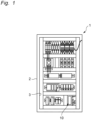
- a control device 10 of one embodiment of the present disclosure is attached to a panel 1 illustrated in Fig. 1 , for example.
- the panel 1 includes a casing 2 provided with an opening 3 opened and closed by a lid (not illustrated).
- the control device 10 is arranged inside the casing 2.
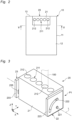
- the control device 10 includes a cover member 11 and a terminal block 20.
- the terminal block 20 is configured to be rotatable with respect to the cover member 11.
- the cover member 11 has a substantially rectangular parallelepiped box shape.
- the terminal block 20 is attached to the cover member 11 in a state of being exposed to an outside of the cover member 11 from a front surface 12 and a side surface 13 of the cover member 11.
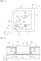
- the terminal block 20 includes a main body 21, a first rotation mechanism unit 22, and a second rotation mechanism unit 23.
- the wiring connection part 211 includes a plurality of wiring holes 212 arranged side by side at equal intervals along the first direction (for example, in an X direction).
- Each of the wiring holes 212 has a substantially circular shape and is configured to be able to house wiring 100. That is, the wiring 100 is connected to the wiring connection part 211 via each of the wiring holes 212.
- the wiring connection part 211 of the main body 21 is exposed to an outside of the control device 10 (see Fig. 2 ).
- the first rotation mechanism unit 22 and the second rotation mechanism unit 23 are configured to be rotatable about an imaginary straight line L extending on the main body 21 along the first direction X with respect to the cover member 11 of the control device 10.
- the main body 21 rotates between a first position P1 (see Fig. 4 ) where the wiring connection part 211 is exposed from the front surface 12 of the cover member 11 and a second position P2 (see Fig. 4 ) where the wiring connection part 211 is exposed from the side surface 13 of the cover member 11.
- the wiring connection part 211 is arranged in the radial direction with respect to the imaginary straight line L of the main body 21 (hereinafter, referred to as radial direction).
- the first rotation mechanism unit 22 is arranged at one end (first end) of the main body 21 (in Fig. 3 , the right end of the main body 21) in the first direction X.
- the first rotation mechanism unit 22 includes a first protrusion 221, a second protrusion 222, and a first rotation support part 223.
- the first protrusion 221 has a substantially cylindrical shape as an example. A substantial center of the first protrusion 221 is arranged on the imaginary straight line L.
- the first protrusion 221 is provided at one end of the main body 21 in the first direction X, and extends in the first direction X and in a direction away from the other end (second end) of the main body 21 (in Fig. 3 , the left end of the main body 21) in the first direction X.
- the second protrusion 222 has a substantially cylindrical shape as an example and has substantially the same length in the first direction X as that of the first protrusion 221.
- the second protrusion 222 is provided at one end of the main body 21 in the first direction X.
- the second protrusion 222 extends in the first direction X and in a direction away from the other end of the main body 21 in the first direction X.
- the second protrusion 222 is arranged at an interval from the first protrusion 221 in the radial direction with respect to the imaginary straight line L.
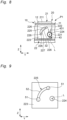
- the first rotation support part 223, which has a substantially rectangular plate shape as an example, includes a first housing hole 224 for housing the first protrusion 221 and a first guide groove 225 for housing the second protrusion 222.
- the first housing hole 224 has a substantially circular shape slightly larger in diameter than the first protrusion 221 as an example. A substantial center of the first housing hole 224 is arranged on the imaginary straight line L.
- the first guide groove 225 is arranged at an interval from the first housing hole 224 in the radial direction.
- the first guide groove 225 extends in a circumferential direction with respect to the imaginary straight line L (hereinafter, referred to as circumferential direction) and houses the second protrusion 222 movably in the circumferential direction.
- the first guide groove 225 has an about 1/4 arc shape as viewed along the first direction X, and penetrates the first rotation support part 223 in the first direction X. Both ends of the first guide groove 225 in the circumferential direction are each provided with a holding protrusion 226.
- Each of the holding protrusions 226 extends in the radial direction from a side surface 227 extending in the circumferential direction of the first guide groove 225.
- Each of the holding protrusions 226 is configured to be able to hold the second protrusion 222 at one end or the other end in the circumferential direction.
- the second rotation mechanism unit 23 is arranged at the other end of the main body 21 in the first direction X.
- the second rotation mechanism unit 23 includes a third protrusion 231 (see Fig. 5 ), a fourth protrusion 232 (see Fig. 5 ), and a second rotation support part 233.
- the third protrusion 231 has substantially the same size as that of the first protrusion 221 as an example. That is, the third protrusion 231 has a substantially cylindrical shape, and a substantial center of the third protrusion 221 is arranged on the imaginary straight line L. In the present embodiment, the third protrusion 231 is provided at the other end of the main body 21 in the first direction X. The third protrusion 231 extends in the first direction X and in a direction away from one end of the main body 21 in the first direction X.
- the fourth protrusion 232 has substantially the same size as that of the second protrusion 222 as an example. That is, the fourth protrusion 232 has a substantially cylindrical shape and has substantially the same length in the first direction X as that of the third protrusion 231. In the present embodiment, the fourth protrusion 232 is provided at the other end of the main body 21 in the first direction X. The fourth protrusion 232 extends in the first direction X and in a direction away from one end of the main body 21 in the first direction X. The fourth protrusion 232 is arranged at an interval from the third protrusion 231 in the radial direction with respect to the imaginary straight line L.
- the second rotation support part 233 which has a substantially rectangular plate shape as an example, includes a second housing hole (not illustrated) for housing the third protrusion 231 and a second guide groove 235 for housing the fourth protrusion 232.
- the second rotation support part 233 has substantially the same shape and size as those of the first rotation support part 223.
- the second housing hole has substantially the same shape and size as those of the first housing hole 224 (see Fig. 4 ) as an example. That is, the second housing hole has a substantially circular shape slightly larger in diameter than the third protrusion 231, and a substantial center of the second housing hole is arranged on the imaginary straight line L.
- the second guide groove 235 is arranged at an interval from the second housing hole in the radial direction.
- the second guide groove 235 extends in the circumferential direction and houses the fourth protrusion 232 movably in the circumferential direction.
- the second guide groove 235 has substantially the same shape and size as those of the first guide groove 225. That is, the second guide groove 235 has about 1/4 arc shape as viewed along the first direction X, and penetrates the second rotation support part 233 in the first direction X. Both ends of the second guide groove 235 in the circumferential direction are each provided with a holding protrusion (not illustrated).
- Each of the holding protrusions extends in the radial direction from a side surface extending in the circumferential direction of the second guide groove 235.
- Each of the holding protrusions is configured to be able to hold the fourth protrusion 232 at one end or the other end in the circumferential direction.
- the first rotation support part 223 and the second rotation support part 233 are fixed to the cover member 11 of the control device 10. Inside the cover member 11 is provided with a substrate 30 supported by the cover member 11 and electrically connected to the terminal block 20. As an example, when a main body unit 21 is positioned at the first position P1, the substrate 30 is arranged more inside the cover member 11 than the terminal block 20.
- the terminal block 20 can exhibit the following effects.
- the terminal block 20 includes the main body 21 including the wiring connection part 211 to which the wiring is connected, the first rotation mechanism unit 22 arranged at one end of the main body 21 in the first direction, and the second rotation mechanism unit 23 arranged at the other end of the main body 21 in the first direction.
- the first rotation mechanism unit 22 and the second rotation mechanism unit 23 are configured that the main body 21 is rotatable about the imaginary straight line extending along the first direction X with respect to the control device 10.
- the wiring connection part 211 is arranged at one end of the main body 21 in the radial direction with respect to the imaginary straight line. With such configuration, when attached to the control device 10, the terminal block 20 can be rotated in accordance with the direction in which the wiring is routed. As a result, in the panel 1 in which the control device 10 is housed, it is possible to save the space for routing the wiring, and achieve the terminal block capable of downsizing the panel 1.
- the terminal block 20 can arbitrarily adopt any one or more of the plurality of configurations below. That is, any one or more of the plurality of configurations below can be arbitrarily deleted when included in the embodiment, and can be arbitrarily added when not included in the embodiment. By adopting such configuration, it is possible to more reliably achieve a terminal block capable of downsizing the panel 1.
- the first rotation mechanism unit 22 includes the first protrusion 221, the second protrusion 222, and the first rotation support part 223.
- the first protrusion 221 extends in the first direction and in a direction away from the other end of the main body 21 in the first direction.
- the second protrusion 222 extends in the first direction and in a direction away from the other end of the main body 21 in the first direction.
- the second protrusion 222 is arranged at an interval from the first protrusion 221 in the radial direction with respect to the imaginary straight line.
- the first rotation support part 223 is fixed to the control device 10.
- the first rotation support part 223 includes the first housing hole 224 and the first guide groove 225.
- the first housing hole 224 is arranged on the imaginary straight line and houses the first protrusion 221.
- the first guide groove 225 is arranged at an interval from the first housing hole 224 in the radial direction with respect to the imaginary straight line.
- the first guide groove 225 extends in the circumferential direction with respect to the imaginary straight line.
- the first guide groove 225 houses the second protrusion 222 movably in the circumferential direction.
- the second rotation mechanism unit 23 includes the third protrusion 231, the fourth protrusion 232, and the second rotation support part 233.
- the third protrusion 231 extends in the first direction and in a direction away from one end of the main body 21 in the first direction.
- the fourth protrusion 232 extends in the first direction and in a direction away from one end of the main body 21 in the first direction.
- the fourth protrusion 232 is arranged at an interval from the third protrusion 231 in the radial direction with respect to the imaginary straight line.
- the second rotation support part 233 is fixed to the control device 10 and has the second housing hole and the second guide groove 235.
- the second housing hole is arranged on the imaginary straight line and houses the third protrusion 231.
- the second guide groove 235 is arranged at an interval from the second housing hole in the radial direction with respect to the imaginary straight line.
- the second guide groove 235 extends in the circumferential direction with respect to the imaginary straight line.
- the second guide groove 235 houses the fourth protrusion 232 movably in the circumferential direction.
- the first rotation support part 22 and the second rotation support part 23 are fixed to the cover member 11 of the control device 10.
- the first protrusion 221 and the second protrusion 222 are provided at one end of the main body 21 in the first direction, and the third protrusion 231 and the fourth protrusion 232 are provided at the other end of the main body 21 in the first direction.
- the first guide groove 225 includes a holding protrusion 226 that is provided at each of ends in the circumferential direction and extends in the radial direction from a side surface extending in the circumferential direction, the holding protrusion 226 holding the second protrusion at one of the ends in the circumferential direction.
- the control device 10 can exhibit the following effects.
- the terminal block 20 can also be configured as follows.
- the main body 21 may adopt any configuration including the wiring connection part 211.
- first rotation mechanism unit 22 and the second rotation mechanism unit 23 is configured to be rotatable about the imaginary straight line extending on the main body 21 along the first direction X with respect to the control device 10.
- the first rotation mechanism unit 22 and the second rotation mechanism unit 23 may1 be configured as illustrated in Fig. 6 .
- the first rotation mechanism unit 22 includes a first fixing member 41
- the second rotation mechanism unit 23 includes a second fixing member 42.
- the control device 10 of Fig. 6 as an example, when the main body unit 21 is positioned at the first position P1, the substrate 30 is arranged more inside the cover member 11 than the terminal block 20.
- the first fixing member 41 is configured to be fixable to the substrate 30, and extends from the substrate 30 in the radial direction and in a direction approaching the cover member 11 (for example, upward in a Z direction in Fig. 6 ).
- the first protrusion 221 and the second protrusion 22 are fixed to a surface on the opposite side to a surface opposing the main body 21 in the first direction X of the first fixing member 41.
- the second fixing member 42 is configured to be fixable to the substrate 30, and extends from the substrate 30 in the radial direction and in a direction approaching the cover member 11.
- the third protrusion 231 and the fourth protrusion 232 are fixed to a surface on the opposite side to a surface opposing the main body 21 in the first direction X of the second fixing member 42.
- first rotation mechanism unit 22 and the second rotation mechanism unit 23 may be configured as illustrated in Figs. 7 and 8 .
- the first rotation mechanism unit 22 includes the first fixing member 41 and a first connection member 43
- the second rotation mechanism unit 23 includes the second fixing member 42 and a second connection member 44.
- the first protrusion 221, the first fixing member 41, the third protrusion 231, and the second fixing member 42 each have conductivity.
- first substrate 31, second substrate 32, and third substrate 33 three substrates (hereinafter, referred to as first substrate 31, second substrate 32, and third substrate 33) are arranged inside the cover member 11.
- the first substrate 31, the second substrate 32, and the third substrate 33 are configured separately from one another, and are supported by the cover member 11.
- the first substrate 31 is arranged on the other end side (for example, the lower side in the Z direction in Fig. 7 ) of the terminal block 20 in the radial direction.
- the first fixing member 41 is fixed to one end of the first substrate 31 in the first direction X (for example, the right end of Fig. 7 ), and the second fixing member 42 is fixed to the other end of the first substrate 31 in the first direction X (for example, the left end of Fig. 7 ).
- the second substrate 32 is arranged on one end side in the first direction X with respect to the first substrate 31 with a gap from the first substrate 31.
- the third substrate 33 is arranged on the other end side in the first direction X with respect to the first substrate 31 with a gap from the first substrate 31.
- the first connection member 43 has conductivity and is arranged between the first rotation support part 223 and the first fixing member 41 in the first direction X.
- the first connection member 43 connects the first protrusion 221 and the second substrate 32.
- the first substrate 31 and the second substrate 32 are electrically connected via the first protrusion 221, the first fixing member 41, and the first connection member 43.
- the second connection member 44 has conductivity and is arranged between the second rotation support part 233 and the second fixing member 42 in the first direction X.
- the second connection member 44 is connected to the third protrusion 231 and the third substrate 33.
- the first substrate 31 and the third substrate 33 are electrically connected via the third protrusion 231, the second fixing member 42, and the second connection member 44.
- the first connection member 43 any configuration that can be connected to the first protrusion 221 and the second substrate 32 may be adopted.
- the first connection member 43 of Fig. 8 includes a pair of elastic members 431 that elastically deform in the radial direction and in a direction along the second substrate 32 (for example, in a Y direction) and can sandwich the first protrusion 221.
- the second connection member 44 may also be configured similarly to the first connection member 43.
- the first rotation support part 223 of Fig. 8 includes a pair of holding protrusions 226 protruding in directions approaching each other, each holding protrusion being provided at both ends of the first guide groove 225. This makes it possible to easily hold the main body 21 at the first position P1 or the second position P2.
- the second rotation support part 233 may also be configured similarly to the first rotation support part 223.
- the first rotation support part 223 may be configured as illustrated in Fig. 9 .
- the first guide groove 225 includes through holes 51 provided at each of both ends in the circumferential direction and a bottomed groove part 52 connected to the two through holes 51.
- the holding protrusion 226 can be omitted.
- the second rotation support part 233 may also be configured similarly to the first rotation support part 223.
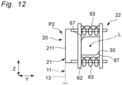
- the first rotation mechanism unit 22 and the second rotation mechanism unit 23 may be configured as illustrated in Figs. 10 to 12 .
- the first rotation mechanism unit 22 includes a first rotation shaft part 61, a first sandwiching member 62, and a first biasing member 63
- the second rotation mechanism unit 23 includes a second rotation shaft part 64, a second sandwiching member 65, and a second biasing member.
- the substrate 30 is connected to an end of the main body 21 on an opposite side to the wiring connection part 211 in the radial direction.
- Figs. 11 and 12 illustrate the first rotation mechanism unit 22.
- the first rotation shaft part 61 is arranged on the substrate 30 and extends along the first direction X.
- the first rotation shaft part 61 is fixed to the cover member 11.
- the first sandwiching member 62 has a substantially rectangular plate shape as an example, and is arranged to be able to sandwich the first rotation shaft part 61 together with the substrate 30 in the radial direction.
- the first biasing member 63 is configured by two coil springs arranged on both sides of the first rotation shaft part 61 in the radial direction and a direction along the substrate 30 (for example, in the Y direction). The first biasing member 63 is connected to the substrate 30 and the first sandwiching member 62, and biases the first sandwiching member 62 in a direction approaching the substrate 30.
- the second rotation shaft part 64 is arranged on the substrate 30 and extends along the first direction X.
- the second rotation shaft part 64 is arranged coaxially with the first rotation shaft part 61 and is fixed to the cover member 11.
- the second sandwiching member 65 has a substantially rectangular plate shape as an example, and is arranged to be able to sandwich the second rotation shaft part 64 together with the substrate 30 in the radial direction.
- the second biasing member is configured by coil springs arranged on both sides of the second rotation shaft part 64 in the radial direction and a direction along the substrate 30.
- the second biasing member is connected to the substrate 30 and the second sandwiching member 65, and biases the second sandwiching member 65 in a direction approaching the substrate 30.
- the terminal block 20 of Figs. 10 to 12 is held at the first position P1 or the second position P2 by the biasing forces of the first biasing member 62 and the second biasing member 66.
- each of the first rotation shaft part 61 and the second rotation shaft part 64 has a quadrangular shape in which a pair of corner parts 67 opposing each other are curved when viewed along the first direction X.
- the curved corner parts facilitate rotation of the main body 21 about the imaginary straight line L.
- the terminal block 20 of the present disclosure can downsize the panel 1 with various configurations.
- the first rotation mechanism unit 22 and the second rotation mechanism unit 23 are not limited to have the configurations same as each other, and may have configurations different from each other.
- the first rotation mechanism unit 22 and the second rotation mechanism unit 23 may be configured such that the first rotation mechanism unit 22 has the configuration illustrated in Fig. 6 and the second rotation mechanism unit 23 has the configuration illustrated in Figs. 7 and 8 .
- the terminal block 20 may be, for example, a screw connection type terminal block, or a push-in connection type terminal block.
- the terminal block of the present disclosure may be applied to a control device arranged in a control panel, for example.
- control device of the present disclosure may be applied to a control panel, for example.
Landscapes
- Connections Arranged To Contact A Plurality Of Conductors (AREA)
Claims (3)
- Dispositif de commande (10), comprenant :un bloc terminal (20) comprenant un corps principal (21) comprenant une partie de connexion de câblage (211) à laquelle le câblage peut être connecté ;et un élément couvercle (11) auquel le bloc terminal (20) est fixé dans un état où la partie de connexion de câblage (211) est exposée à un extérieur du dispositif de commande (10), ledit corps principal (21) étant conçu pour pouvoir tourner par rapport à l'élément couvercle (11), ledit bloc terminal (20) pouvant être fixé au dispositif de commande et fixé à l'élément couvercle (11) dans un état dans lequel il est exposé à un extérieur de l'élément couvercle (11) à partir d'une surface avant (12) et d'une surface latérale (13) de l'élément couvercle (11), ledit bloc terminal comprenant en outre :une première unité de mécanisme de rotation (22) agencée au niveau d'une première extrémité dans une première direction du corps principal (21) ; etune seconde unité de mécanisme de rotation (23) agencée au niveau d'une seconde extrémité dans la première direction du corps principal (21),ladite première unité de mécanisme de rotation (22) et ladite seconde unité de mécanisme de rotation (23) étant conçues pour que le corps principal (21) puisse tourner autour d'une ligne droite imaginaire s'étendant le long de la première direction par rapport au dispositif de commande, etladite partie de connexion de câblage (211) étant agencée au niveau d'une extrémité du corps principal (21) dans une direction radiale par rapport à la ligne droite imaginaire,ladite première unité de mécanisme de rotation (22) comprenant une première saillie (221) qui s'étend dans la première direction et dans une direction s'éloignant de la seconde extrémité du corps principal (21) dans la première direction, une deuxième saillie (222) qui s'étend dans la première direction et dans une direction s'éloignant de la seconde extrémité du corps principal (21) dans la première direction, et étant agencée à un intervalle de la première saillie (221) dans la direction radiale par rapport à la ligne droite imaginaire, etune première partie de support de rotation (223) qui comprend un premier trou de logement (224) qui est agencé sur la ligne droite imaginaire et loge la première saillie (221), et une première rainure de guidage (225) qui est agencée à un intervalle du premier trou de logement (224) dans la direction radiale, s'étend dans une direction circonférentielle par rapport à la ligne droite imaginaire, et loge la seconde saillie (222) de manière mobile dans la direction circonférentielle, la première partie de support de rotation (225) étant fixée au dispositif de commande, etladite seconde unité de mécanisme de rotation (23) comprenant une troisième saillie (231) qui s'étend dans la première direction et dans une direction s'éloignant de la première extrémité du corps principal (21) dans la première direction, une quatrième saillie (232) qui s'étend dans la première direction et dans une direction s'éloignant de la première extrémité du corps principal (21) dans la première direction, et étant agencée à un intervalle de la troisième saillie (231) dans la direction radiale par rapport à la ligne droite imaginaire, etune seconde partie de support de rotation (233) qui comprend un second trou de logement qui est agencé sur la ligne droite imaginaire et loge la troisième saillie (231), et une seconde rainure de guidage (235) qui est agencée à un intervalle du second trou de logement dans la direction radiale, s'étend dans la direction circonférentielle, et loge la quatrième saillie (232) de manière mobile dans la direction circonférentielle, la seconde partie de support de rotation (233) étant fixée au dispositif de commande,ladite première partie de support de rotation (22) et ladite seconde partie de support de rotation (23) étant fixées à l'élément couvercle (11), ladite première saillie (221) et ladite deuxième saillie (222) étant prévues au niveau de la première extrémité du corps principal (21) dans la première direction, etladite troisième saillie (231) et ladite quatrième saillie (232) étant prévues au niveau de la seconde extrémité du corps principal (21) dans la première direction.
- Dispositif de commande (10) selon la revendication 1,
ladite première rainure de guidage (225) comprenant une saillie de maintien (226) qui est prévue au niveau de chacune des extrémités dans la direction circonférentielle et s'étend dans la direction radiale à partir d'une surface latérale s'étendant dans la direction circonférentielle, la saillie de maintien maintenant la deuxième saillie (222) au niveau de l'une des extrémités dans la direction circonférentielle. - Dispositif de commande (10) selon la revendication 1 oula revendication 2, ladite première rainure de guidage (225) comprenant des trous traversants (51) qui sont prévus au niveau de chacune des extrémités dans la direction circonférentielle et chacun pénétrant dans la première partie de support de rotation (223) dans la première direction, etune partie de rainure inférieure (52) qui est reliée aux trous traversants (51) au niveau des extrémités dans la direction circonférentielle et s'ouvrant sur une surface sur un côté opposé à une surface opposée au corps principal (21) dans la première direction.
Applications Claiming Priority (1)
| Application Number | Priority Date | Filing Date | Title |
|---|---|---|---|
| JP2021129258A JP7690811B2 (ja) | 2021-08-05 | 2021-08-05 | 端子台および制御機器 |
Publications (2)
| Publication Number | Publication Date |
|---|---|
| EP4131663A1 EP4131663A1 (fr) | 2023-02-08 |
| EP4131663B1 true EP4131663B1 (fr) | 2025-04-02 |
Family
ID=82786716
Family Applications (1)
| Application Number | Title | Priority Date | Filing Date |
|---|---|---|---|
| EP22187917.4A Active EP4131663B1 (fr) | 2021-08-05 | 2022-07-29 | Bloc terminal et dispositif de commande |
Country Status (4)
| Country | Link |
|---|---|
| US (1) | US12347993B2 (fr) |
| EP (1) | EP4131663B1 (fr) |
| JP (1) | JP7690811B2 (fr) |
| CN (1) | CN115911938A (fr) |
Family Cites Families (22)
| Publication number | Priority date | Publication date | Assignee | Title |
|---|---|---|---|---|
| JPH0262678U (fr) * | 1988-10-31 | 1990-05-10 | ||
| US5299945A (en) * | 1992-12-28 | 1994-04-05 | Connectron, Inc. | Electrical apparatus |
| US6238234B1 (en) * | 2000-02-26 | 2001-05-29 | Marconi Communications, Inc. | Terminal block with reduced dielectric material |
| US7070438B2 (en) * | 2004-03-31 | 2006-07-04 | Jst Corporation | Connector lever lock |
| US6971894B2 (en) * | 2004-03-31 | 2005-12-06 | Jst Corporation | Dual action mechanical assisted connector |
| US6899554B1 (en) * | 2004-04-19 | 2005-05-31 | Jst Corporation | Dual action mechanical assisted connector |
| WO2006110134A1 (fr) * | 2005-04-08 | 2006-10-19 | Jst Corporation | Connecteur mecanique assiste a double action |
| JP4739084B2 (ja) | 2006-04-03 | 2011-08-03 | キヤノン株式会社 | シート給送装置及び画像形成装置 |
| JP2015230637A (ja) | 2014-06-06 | 2015-12-21 | アズビル株式会社 | 制御機器における配線作業確認方法 |
| WO2016009804A1 (fr) * | 2014-07-16 | 2016-01-21 | 木谷電器株式会社 | Dispositif de connexion électrique, plaque à bornes le comprenant, système de génération d'énergie photovoltaïque et appareil électrique |
| CN205355324U (zh) * | 2015-12-31 | 2016-06-29 | 生迪光电科技股份有限公司 | 一种用于隐藏式插头的旋转结构 |
| CN105680192B (zh) | 2016-04-06 | 2018-06-22 | 盐城工学院 | 一种开关柜仪表室用可旋转式接线端子安装结构 |
| US10251284B2 (en) * | 2016-05-06 | 2019-04-02 | S.J. Electro Systems, Inc. | Easy assembly control panel |
| US10084396B2 (en) * | 2016-06-21 | 2018-09-25 | Rockwell Automation Technologies, Inc. | System and method for simplifying interconnection between panel controls and motor power units |
| JP2018101520A (ja) * | 2016-12-20 | 2018-06-28 | 三菱電機株式会社 | 端子台および気中遮断器 |
| CN208423424U (zh) * | 2018-04-24 | 2019-01-22 | 山东春旭电气有限公司 | 接线端子固定装置 |
| CN208189808U (zh) | 2018-05-07 | 2018-12-04 | 烟台瑞运电子有限公司 | 电控柜内接线端子固定装置 |
| US10490916B1 (en) * | 2018-11-13 | 2019-11-26 | Dinkle Enterprise Co., Ltd. | Light-emitting terminal block structure |
| CN112636050B (zh) * | 2019-09-24 | 2023-05-26 | Oppo广东移动通信有限公司 | 电源适配器 |
| GB2589305B (en) * | 2019-10-23 | 2023-12-20 | Texecom Ltd | Terminal block mounting |
| CN111478075A (zh) * | 2020-05-25 | 2020-07-31 | 镇江易拓电气有限公司 | 母线插接系统 |
| CN212462071U (zh) | 2020-07-22 | 2021-02-02 | 町洋企业股份有限公司 | 具有把手的端子台 |
-
2021
- 2021-08-05 JP JP2021129258A patent/JP7690811B2/ja active Active
-
2022
- 2022-07-27 CN CN202210891142.6A patent/CN115911938A/zh active Pending
- 2022-07-29 EP EP22187917.4A patent/EP4131663B1/fr active Active
- 2022-08-03 US US17/880,088 patent/US12347993B2/en active Active
Also Published As
| Publication number | Publication date |
|---|---|
| CN115911938A (zh) | 2023-04-04 |
| EP4131663A1 (fr) | 2023-02-08 |
| JP2023023603A (ja) | 2023-02-16 |
| JP7690811B2 (ja) | 2025-06-11 |
| US12347993B2 (en) | 2025-07-01 |
| US20230044689A1 (en) | 2023-02-09 |
Similar Documents
| Publication | Publication Date | Title |
|---|---|---|
| CN102037532B (zh) | 旋转式电气开关 | |
| US9546606B2 (en) | Electronic throttle body assembly | |
| US8141207B2 (en) | Two-axis hinge device and mobile terminal apparatus | |
| US7642884B2 (en) | Bi-stable trip-free relay configuration | |
| CN101539165B (zh) | 双轴铰链装置和移动终端装置 | |
| EP4131663B1 (fr) | Bloc terminal et dispositif de commande | |
| EP0546240B1 (fr) | Interrupteur électrique | |
| US5735179A (en) | Device for providing axial and spatial misalignment compensation between a rotatable component and a rotating means | |
| US7161104B2 (en) | Trip-free PCB mountable relay configuration and method | |
| US6210179B1 (en) | Field-bus connecting device | |
| US20100170713A1 (en) | Enclosure with tubular coupling for containing electronic components | |
| US8060158B2 (en) | Hinge apparatus for portable terminal | |
| CN111200206A (zh) | 电气连接部位的罩结构 | |
| JP4091459B2 (ja) | モータ | |
| US8180413B2 (en) | Hinge structure and folding mobile terminal using the same | |
| JP2000151140A (ja) | 電線ガイド付ヒンジ及び電子機器 | |
| CN109121471A (zh) | 数据总线的电子接线板 | |
| CN210921926U (zh) | 风门装置 | |
| KR200198278Y1 (ko) | 휴대용복합정보단말기의힌지장치 | |
| JPH087501Y2 (ja) | 自動販売機の電装品収納箱 | |
| KR19990032598U (ko) | 전화교환기의 알람모듈용 배터리 장착기구 | |
| JP2002319448A (ja) | コンセントユニット | |
| WO2012101986A1 (fr) | Dispositif électronique et élément de contact | |
| JPH0652176U (ja) | 電子機器のケーシング装置 | |
| HK1063383A1 (en) | Connector with usb connection |
Legal Events
| Date | Code | Title | Description |
|---|---|---|---|
| PUAI | Public reference made under article 153(3) epc to a published international application that has entered the european phase |
Free format text: ORIGINAL CODE: 0009012 |
|
| STAA | Information on the status of an ep patent application or granted ep patent |
Free format text: STATUS: REQUEST FOR EXAMINATION WAS MADE |
|
| 17P | Request for examination filed |
Effective date: 20220729 |
|
| AK | Designated contracting states |
Kind code of ref document: A1 Designated state(s): AL AT BE BG CH CY CZ DE DK EE ES FI FR GB GR HR HU IE IS IT LI LT LU LV MC MK MT NL NO PL PT RO RS SE SI SK SM TR |
|
| GRAP | Despatch of communication of intention to grant a patent |
Free format text: ORIGINAL CODE: EPIDOSNIGR1 |
|
| STAA | Information on the status of an ep patent application or granted ep patent |
Free format text: STATUS: GRANT OF PATENT IS INTENDED |
|
| RIC1 | Information provided on ipc code assigned before grant |
Ipc: H05K 7/14 20060101ALN20241029BHEP Ipc: H01R 9/24 20060101ALI20241029BHEP Ipc: H01R 9/16 20060101AFI20241029BHEP |
|
| RIC1 | Information provided on ipc code assigned before grant |
Ipc: H05K 7/14 20060101ALN20241105BHEP Ipc: H01R 9/24 20060101ALI20241105BHEP Ipc: H01R 9/16 20060101AFI20241105BHEP |
|
| INTG | Intention to grant announced |
Effective date: 20241114 |
|
| GRAS | Grant fee paid |
Free format text: ORIGINAL CODE: EPIDOSNIGR3 |
|
| GRAA | (expected) grant |
Free format text: ORIGINAL CODE: 0009210 |
|
| STAA | Information on the status of an ep patent application or granted ep patent |
Free format text: STATUS: THE PATENT HAS BEEN GRANTED |
|
| AK | Designated contracting states |
Kind code of ref document: B1 Designated state(s): AL AT BE BG CH CY CZ DE DK EE ES FI FR GB GR HR HU IE IS IT LI LT LU LV MC MK MT NL NO PL PT RO RS SE SI SK SM TR |
|
| REG | Reference to a national code |
Ref country code: GB Ref legal event code: FG4D |
|
| REG | Reference to a national code |
Ref country code: CH Ref legal event code: EP |
|
| REG | Reference to a national code |
Ref country code: DE Ref legal event code: R096 Ref document number: 602022012487 Country of ref document: DE |
|
| REG | Reference to a national code |
Ref country code: IE Ref legal event code: FG4D |
|
| REG | Reference to a national code |
Ref country code: NL Ref legal event code: MP Effective date: 20250402 |
|
| PG25 | Lapsed in a contracting state [announced via postgrant information from national office to epo] |
Ref country code: NL Free format text: LAPSE BECAUSE OF FAILURE TO SUBMIT A TRANSLATION OF THE DESCRIPTION OR TO PAY THE FEE WITHIN THE PRESCRIBED TIME-LIMIT Effective date: 20250402 |
|
| REG | Reference to a national code |
Ref country code: AT Ref legal event code: MK05 Ref document number: 1782260 Country of ref document: AT Kind code of ref document: T Effective date: 20250402 |
|
| PG25 | Lapsed in a contracting state [announced via postgrant information from national office to epo] |
Ref country code: FI Free format text: LAPSE BECAUSE OF FAILURE TO SUBMIT A TRANSLATION OF THE DESCRIPTION OR TO PAY THE FEE WITHIN THE PRESCRIBED TIME-LIMIT Effective date: 20250402 Ref country code: ES Free format text: LAPSE BECAUSE OF FAILURE TO SUBMIT A TRANSLATION OF THE DESCRIPTION OR TO PAY THE FEE WITHIN THE PRESCRIBED TIME-LIMIT Effective date: 20250402 Ref country code: PT Free format text: LAPSE BECAUSE OF FAILURE TO SUBMIT A TRANSLATION OF THE DESCRIPTION OR TO PAY THE FEE WITHIN THE PRESCRIBED TIME-LIMIT Effective date: 20250804 |
|
| PGFP | Annual fee paid to national office [announced via postgrant information from national office to epo] |
Ref country code: DE Payment date: 20250716 Year of fee payment: 4 |
|
| REG | Reference to a national code |
Ref country code: LT Ref legal event code: MG9D |
|
| PG25 | Lapsed in a contracting state [announced via postgrant information from national office to epo] |
Ref country code: GR Free format text: LAPSE BECAUSE OF FAILURE TO SUBMIT A TRANSLATION OF THE DESCRIPTION OR TO PAY THE FEE WITHIN THE PRESCRIBED TIME-LIMIT Effective date: 20250703 Ref country code: NO Free format text: LAPSE BECAUSE OF FAILURE TO SUBMIT A TRANSLATION OF THE DESCRIPTION OR TO PAY THE FEE WITHIN THE PRESCRIBED TIME-LIMIT Effective date: 20250702 |
|
| PG25 | Lapsed in a contracting state [announced via postgrant information from national office to epo] |
Ref country code: PL Free format text: LAPSE BECAUSE OF FAILURE TO SUBMIT A TRANSLATION OF THE DESCRIPTION OR TO PAY THE FEE WITHIN THE PRESCRIBED TIME-LIMIT Effective date: 20250402 |
|
| PG25 | Lapsed in a contracting state [announced via postgrant information from national office to epo] |
Ref country code: BG Free format text: LAPSE BECAUSE OF FAILURE TO SUBMIT A TRANSLATION OF THE DESCRIPTION OR TO PAY THE FEE WITHIN THE PRESCRIBED TIME-LIMIT Effective date: 20250402 |
|
| PG25 | Lapsed in a contracting state [announced via postgrant information from national office to epo] |
Ref country code: HR Free format text: LAPSE BECAUSE OF FAILURE TO SUBMIT A TRANSLATION OF THE DESCRIPTION OR TO PAY THE FEE WITHIN THE PRESCRIBED TIME-LIMIT Effective date: 20250402 |
|
| PG25 | Lapsed in a contracting state [announced via postgrant information from national office to epo] |
Ref country code: AT Free format text: LAPSE BECAUSE OF FAILURE TO SUBMIT A TRANSLATION OF THE DESCRIPTION OR TO PAY THE FEE WITHIN THE PRESCRIBED TIME-LIMIT Effective date: 20250402 |
|
| PG25 | Lapsed in a contracting state [announced via postgrant information from national office to epo] |
Ref country code: RS Free format text: LAPSE BECAUSE OF FAILURE TO SUBMIT A TRANSLATION OF THE DESCRIPTION OR TO PAY THE FEE WITHIN THE PRESCRIBED TIME-LIMIT Effective date: 20250702 |
|
| PG25 | Lapsed in a contracting state [announced via postgrant information from national office to epo] |
Ref country code: IS Free format text: LAPSE BECAUSE OF FAILURE TO SUBMIT A TRANSLATION OF THE DESCRIPTION OR TO PAY THE FEE WITHIN THE PRESCRIBED TIME-LIMIT Effective date: 20250802 |
|
| PG25 | Lapsed in a contracting state [announced via postgrant information from national office to epo] |
Ref country code: LV Free format text: LAPSE BECAUSE OF FAILURE TO SUBMIT A TRANSLATION OF THE DESCRIPTION OR TO PAY THE FEE WITHIN THE PRESCRIBED TIME-LIMIT Effective date: 20250402 |
|
| REG | Reference to a national code |
Ref country code: DE Ref legal event code: R097 Ref document number: 602022012487 Country of ref document: DE |
|
| PG25 | Lapsed in a contracting state [announced via postgrant information from national office to epo] |
Ref country code: DK Free format text: LAPSE BECAUSE OF FAILURE TO SUBMIT A TRANSLATION OF THE DESCRIPTION OR TO PAY THE FEE WITHIN THE PRESCRIBED TIME-LIMIT Effective date: 20250402 Ref country code: SM Free format text: LAPSE BECAUSE OF FAILURE TO SUBMIT A TRANSLATION OF THE DESCRIPTION OR TO PAY THE FEE WITHIN THE PRESCRIBED TIME-LIMIT Effective date: 20250402 |
|
| PG25 | Lapsed in a contracting state [announced via postgrant information from national office to epo] |
Ref country code: CZ Free format text: LAPSE BECAUSE OF FAILURE TO SUBMIT A TRANSLATION OF THE DESCRIPTION OR TO PAY THE FEE WITHIN THE PRESCRIBED TIME-LIMIT Effective date: 20250402 |
|
| PG25 | Lapsed in a contracting state [announced via postgrant information from national office to epo] |
Ref country code: EE Free format text: LAPSE BECAUSE OF FAILURE TO SUBMIT A TRANSLATION OF THE DESCRIPTION OR TO PAY THE FEE WITHIN THE PRESCRIBED TIME-LIMIT Effective date: 20250402 |
|
| PG25 | Lapsed in a contracting state [announced via postgrant information from national office to epo] |
Ref country code: SK Free format text: LAPSE BECAUSE OF FAILURE TO SUBMIT A TRANSLATION OF THE DESCRIPTION OR TO PAY THE FEE WITHIN THE PRESCRIBED TIME-LIMIT Effective date: 20250402 |
|
| PG25 | Lapsed in a contracting state [announced via postgrant information from national office to epo] |
Ref country code: IT Free format text: LAPSE BECAUSE OF FAILURE TO SUBMIT A TRANSLATION OF THE DESCRIPTION OR TO PAY THE FEE WITHIN THE PRESCRIBED TIME-LIMIT Effective date: 20250402 |
|
| PLBE | No opposition filed within time limit |
Free format text: ORIGINAL CODE: 0009261 |
|
| STAA | Information on the status of an ep patent application or granted ep patent |
Free format text: STATUS: NO OPPOSITION FILED WITHIN TIME LIMIT |
|
| PG25 | Lapsed in a contracting state [announced via postgrant information from national office to epo] |
Ref country code: RO Free format text: LAPSE BECAUSE OF FAILURE TO SUBMIT A TRANSLATION OF THE DESCRIPTION OR TO PAY THE FEE WITHIN THE PRESCRIBED TIME-LIMIT Effective date: 20250402 |
|
| REG | Reference to a national code |
Ref country code: CH Ref legal event code: L10 Free format text: ST27 STATUS EVENT CODE: U-0-0-L10-L00 (AS PROVIDED BY THE NATIONAL OFFICE) Effective date: 20260211 |
|
| REG | Reference to a national code |
Ref country code: CH Ref legal event code: H13 Free format text: ST27 STATUS EVENT CODE: U-0-0-H10-H13 (AS PROVIDED BY THE NATIONAL OFFICE) Effective date: 20260224 |
|
| 26N | No opposition filed |
Effective date: 20260105 |
|
| PG25 | Lapsed in a contracting state [announced via postgrant information from national office to epo] |
Ref country code: LU Free format text: LAPSE BECAUSE OF NON-PAYMENT OF DUE FEES Effective date: 20250729 |
|
| REG | Reference to a national code |
Ref country code: BE Ref legal event code: MM Effective date: 20250731 |
|
| PG25 | Lapsed in a contracting state [announced via postgrant information from national office to epo] |
Ref country code: BE Free format text: LAPSE BECAUSE OF NON-PAYMENT OF DUE FEES Effective date: 20250731 |
|
| PG25 | Lapsed in a contracting state [announced via postgrant information from national office to epo] |
Ref country code: FR Free format text: LAPSE BECAUSE OF NON-PAYMENT OF DUE FEES Effective date: 20250731 |
|
| PG25 | Lapsed in a contracting state [announced via postgrant information from national office to epo] |
Ref country code: CH Free format text: LAPSE BECAUSE OF NON-PAYMENT OF DUE FEES Effective date: 20250731 |