EP4131659B1 - Steckdosenmechanismus und entsprechende steckdose - Google Patents
Steckdosenmechanismus und entsprechende steckdose Download PDFInfo
- Publication number
- EP4131659B1 EP4131659B1 EP22184068.9A EP22184068A EP4131659B1 EP 4131659 B1 EP4131659 B1 EP 4131659B1 EP 22184068 A EP22184068 A EP 22184068A EP 4131659 B1 EP4131659 B1 EP 4131659B1
- Authority
- EP
- European Patent Office
- Prior art keywords
- electrical
- plane
- female terminal
- power socket
- insulating base
- Prior art date
- Legal status (The legal status is an assumption and is not a legal conclusion. Google has not performed a legal analysis and makes no representation as to the accuracy of the status listed.)
- Active
Links
- 239000004020 conductor Substances 0.000 claims description 99
- 238000003780 insertion Methods 0.000 claims description 92
- 230000037431 insertion Effects 0.000 claims description 92
- 239000002184 metal Substances 0.000 claims description 23
- 229910052751 metal Inorganic materials 0.000 claims description 23
- 239000012528 membrane Substances 0.000 claims description 4
- 239000012777 electrically insulating material Substances 0.000 claims 1
- 238000009429 electrical wiring Methods 0.000 description 4
- RYGMFSIKBFXOCR-UHFFFAOYSA-N Copper Chemical compound [Cu] RYGMFSIKBFXOCR-UHFFFAOYSA-N 0.000 description 2
- 229910052802 copper Inorganic materials 0.000 description 2
- 239000010949 copper Substances 0.000 description 2
- 239000011810 insulating material Substances 0.000 description 2
- 239000000463 material Substances 0.000 description 2
- 239000007769 metal material Substances 0.000 description 2
- 238000012986 modification Methods 0.000 description 2
- 230000004048 modification Effects 0.000 description 2
- 230000007935 neutral effect Effects 0.000 description 2
- 230000035515 penetration Effects 0.000 description 2
- 230000001681 protective effect Effects 0.000 description 2
- 229910001369 Brass Inorganic materials 0.000 description 1
- 229910000906 Bronze Inorganic materials 0.000 description 1
- 239000010951 brass Substances 0.000 description 1
- 239000010974 bronze Substances 0.000 description 1
- KUNSUQLRTQLHQQ-UHFFFAOYSA-N copper tin Chemical compound [Cu].[Sn] KUNSUQLRTQLHQQ-UHFFFAOYSA-N 0.000 description 1
- 229920002457 flexible plastic Polymers 0.000 description 1
- 229910001092 metal group alloy Inorganic materials 0.000 description 1
- 229920003023 plastic Polymers 0.000 description 1
Images


Classifications
-
- H—ELECTRICITY
- H01—ELECTRIC ELEMENTS
- H01R—ELECTRICALLY-CONDUCTIVE CONNECTIONS; STRUCTURAL ASSOCIATIONS OF A PLURALITY OF MUTUALLY-INSULATED ELECTRICAL CONNECTING ELEMENTS; COUPLING DEVICES; CURRENT COLLECTORS
- H01R24/00—Two-part coupling devices, or either of their cooperating parts, characterised by their overall structure
- H01R24/76—Two-part coupling devices, or either of their cooperating parts, characterised by their overall structure with sockets, clips or analogous contacts and secured to apparatus or structure, e.g. to a wall
- H01R24/78—Two-part coupling devices, or either of their cooperating parts, characterised by their overall structure with sockets, clips or analogous contacts and secured to apparatus or structure, e.g. to a wall with additional earth or shield contacts
-
- H—ELECTRICITY
- H01—ELECTRIC ELEMENTS
- H01R—ELECTRICALLY-CONDUCTIVE CONNECTIONS; STRUCTURAL ASSOCIATIONS OF A PLURALITY OF MUTUALLY-INSULATED ELECTRICAL CONNECTING ELEMENTS; COUPLING DEVICES; CURRENT COLLECTORS
- H01R11/00—Individual connecting elements providing two or more spaced connecting locations for conductive members which are, or may be, thereby interconnected, e.g. end pieces for wires or cables supported by the wire or cable and having means for facilitating electrical connection to some other wire, terminal, or conductive member, blocks of binding posts
- H01R11/03—Individual connecting elements providing two or more spaced connecting locations for conductive members which are, or may be, thereby interconnected, e.g. end pieces for wires or cables supported by the wire or cable and having means for facilitating electrical connection to some other wire, terminal, or conductive member, blocks of binding posts characterised by the relationship between the connecting locations
- H01R11/05—Individual connecting elements providing two or more spaced connecting locations for conductive members which are, or may be, thereby interconnected, e.g. end pieces for wires or cables supported by the wire or cable and having means for facilitating electrical connection to some other wire, terminal, or conductive member, blocks of binding posts characterised by the relationship between the connecting locations the connecting locations having different types of direct connections
-
- H—ELECTRICITY
- H01—ELECTRIC ELEMENTS
- H01R—ELECTRICALLY-CONDUCTIVE CONNECTIONS; STRUCTURAL ASSOCIATIONS OF A PLURALITY OF MUTUALLY-INSULATED ELECTRICAL CONNECTING ELEMENTS; COUPLING DEVICES; CURRENT COLLECTORS
- H01R13/00—Details of coupling devices of the kinds covered by groups H01R12/70 or H01R24/00 - H01R33/00
- H01R13/02—Contact members
- H01R13/10—Sockets for co-operation with pins or blades
- H01R13/11—Resilient sockets
- H01R13/111—Resilient sockets co-operating with pins having a circular transverse section
-
- H—ELECTRICITY
- H01—ELECTRIC ELEMENTS
- H01R—ELECTRICALLY-CONDUCTIVE CONNECTIONS; STRUCTURAL ASSOCIATIONS OF A PLURALITY OF MUTUALLY-INSULATED ELECTRICAL CONNECTING ELEMENTS; COUPLING DEVICES; CURRENT COLLECTORS
- H01R11/00—Individual connecting elements providing two or more spaced connecting locations for conductive members which are, or may be, thereby interconnected, e.g. end pieces for wires or cables supported by the wire or cable and having means for facilitating electrical connection to some other wire, terminal, or conductive member, blocks of binding posts
- H01R11/03—Individual connecting elements providing two or more spaced connecting locations for conductive members which are, or may be, thereby interconnected, e.g. end pieces for wires or cables supported by the wire or cable and having means for facilitating electrical connection to some other wire, terminal, or conductive member, blocks of binding posts characterised by the relationship between the connecting locations
- H01R11/09—Individual connecting elements providing two or more spaced connecting locations for conductive members which are, or may be, thereby interconnected, e.g. end pieces for wires or cables supported by the wire or cable and having means for facilitating electrical connection to some other wire, terminal, or conductive member, blocks of binding posts characterised by the relationship between the connecting locations the connecting locations being identical
-
- H—ELECTRICITY
- H01—ELECTRIC ELEMENTS
- H01R—ELECTRICALLY-CONDUCTIVE CONNECTIONS; STRUCTURAL ASSOCIATIONS OF A PLURALITY OF MUTUALLY-INSULATED ELECTRICAL CONNECTING ELEMENTS; COUPLING DEVICES; CURRENT COLLECTORS
- H01R4/00—Electrically-conductive connections between two or more conductive members in direct contact, i.e. touching one another; Means for effecting or maintaining such contact; Electrically-conductive connections having two or more spaced connecting locations for conductors and using contact members penetrating insulation
- H01R4/28—Clamped connections, spring connections
- H01R4/48—Clamped connections, spring connections utilising a spring, clip, or other resilient member
- H01R4/4809—Clamped connections, spring connections utilising a spring, clip, or other resilient member using a leaf spring to bias the conductor toward the busbar
- H01R4/4828—Spring-activating arrangements mounted on or integrally formed with the spring housing
- H01R4/48365—Spring-activating arrangements mounted on or integrally formed with the spring housing with integral release means
Definitions
- the present invention generally relates to the field of female electrical connection terminals for power outlets, that is to say electrical connection terminals fitted to power outlets and whose functional part comprises a receiving cell intended to receive a pin of an electrical plug for supplying current to an electrical device connected to the electrical plug.
- the invention relates more precisely to a power socket mechanism comprising an insulating base housing at least one female terminal.
- a power socket mechanism comprises an insulating base in which two female electrical connection terminals are housed, one being supplied by the electrical network with neutral current while the other is supplied with phase current, which insulating base is intended to be housed in an electrical box into which the electrical conductors coming from the network arrive.
- the free end of the electrical conductor inserted into the terminal is forced to adopt an orientation imposed by the terminal, while the rest of the length of electrical conductor is pushed into the bottom of the electrical box, behind the insulating base of the mechanism. 'equipment.
- the electrical conductor is naturally curved.
- the natural curvature adopted by the electrical conductor depends of course on its section, so that the size (also called “overall volume”) of the curved portion of electrical conductor is more or less important depending on whether the electrical conductor has a section more or less large.
- the female electrical connection terminal of the document FR3060873 is bulky, so that the insulating base of the socket mechanism that it equips is itself bulky and leaves little space in the bottom of the electrical box to, on the one hand, accommodate the curved portion of the electrical conductor generated by the connection of the terminal, and, on the other hand, push back the length of the electrical conductor which allowed this connection. This is all the more annoying when the electrical box receiving the socket mechanism is of shallow depth.
- DE 30 36 545 A1 discloses a power socket mechanism comprising an insulating base housing a female terminal and defining four planes extending perpendicular to the direction of insertion.
- the present invention proposes a power socket mechanism which comprises a female electrical connection terminal which is little bulky, which frees up space at its second face, located at the rear of the female terminal, to facilitate the connection of the electrical conductor which supplies it, and to accommodate the naturally curved portion of the electrical conductor.
- the second plane is brought closer to the first plane of the female terminal, so as to free up space at the rear of said female connection terminal.
- the space thus freed facilitates the connection of the female terminal and makes it possible to accommodate the curved portion of the electrical conductor which supplies it.
- the distance separating the first and second planes of the female terminal can be zero, the second plane then being coincident with the first plane.
- the distance separating the first and second planes of the female terminal can still be negative, that is to say that the second plane is located in front of the first plane.
- the space freed at the rear of the terminal is preferably calibrated to fully accommodate the overall volume occupied by the curved portion of the electrical conductor.
- the base of the socket mechanism is designed to adjust to the female terminal and follow the offset of the second plane of the female terminal towards the front, so as to free up space in the bottom of the box electrical which receives it while ensuring, thanks to the thickness of the bottom wall separating the second and third planes, a function of guiding the electrical conductor into the second place of insertion of the female terminal.
- the space freed at the bottom of the box makes it possible to accommodate, without crushing, the curved portion of the electrical conductor supplying each female terminal.
- the conductor guide facilitates the connection of the electrical conductor into the female terminal, without disturbing the natural curvature of the electrical conductor.
- the invention finally relates to a power socket comprising, on the one hand, an equipment support accommodating a power socket mechanism according to the invention, and, on the other hand, a hubcap delimiting a well for inserting a socket an electrical plug, the hubcap having a bottom wall pierced with holes giving access to the female electrical connection terminals arranged in the insulating base of the mechanism.
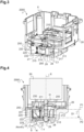
- This power outlet 1 includes a power outlet mechanism 3000; 4000 closed by a hubcap 8 and attached to an equipment support 3.
- the equipment support 3 is used for mounting the base of the socket mechanism in an electrical box 5 to be embedded in the receiving wall.
- the hubcap 8 delimits an insertion well 9 (see figures 11 And 13 ) into which a user can insert an electrical plug 6 (see Figure 4 ) for the purpose of supplying current to an electrical appliance connected to said plug.
- the power socket mechanism 3000; 4000 includes an insulating base 30; 40 with, on the one hand, a side wall which delimits, at the front, a reception opening 35; 45 intended to be closed by the hubcap 8, and, on the other hand, a bottom wall 31; 41 on the interior face of which are provided locations intended to receive electrical connection terminals adapted to establish electrical contact between conductors electrical coming from the electrical network and the conductive elements of the electrical plug plugged into the insertion well 9 of the hubcap 8.
- the insulating base 30 of the power socket mechanism 3000 more specifically comprises three locations 38, 39 to accommodate three electrical connection terminals: two lateral locations 38 intended to receive two female terminals and a central location 39 intended to receive a male terminal.
- female terminal an electrical connection terminal whose functional part includes a receiving cell intended to receive a connection pin 51 of the electrical plug 50 (shown on the figure 4 )
- a “male terminal” means an electrical connection terminal whose functional part comprises an electrical contact element, such as an earth pin6 (or a lyre according to another embodiment not shown), intended to protrude into the insertion well 9 of the hubcap 8 to plug into a socket of the electrical plug 50.
- the earth pin 6 is, generally, that of a Franco-Belgian type socket.
- the earth connection yoke is provided in a German standard socket (type F), not shown here.
- the insertion well 9 of the hubcap 8 opens towards the front and is closed at the rear by a bottom wall 7 (see figures 11 And 13 ) pierced with three orifices, two giving access to the recesses for receiving the female terminals of the socket mechanism, and a third leaving the passage for the earth pin 6.
- the hubcap 8 comprises a protective wall 4, sliding in the insertion well 9 in the manner of a piston wall, provided with orifices in correspondence with the orifices of the bottom wall 7. This protective wall 4 allows you to close the insertion well 9 when the power outlet 1 is unused.
- the socket mechanism integrates particularly advantageous female terminals whose profile allows a profile of the bottom wall of the optimized insulating base which frees up a space at the entrances for the electrical conductors.
- This space facilitates the so-called “wiring” operation by which the electrical conductors are connected to the terminals of the mechanism in an insertion direction imposed by the terminal.
- this space makes it possible to accommodate, without crushing it, the natural curvature of the electrical conductors which is generated between the end of the conductor inserted in the terminal and the remaining length of conductor stored in the bottom of the electrical box.
- the profile of the insulating base 30 of the power socket mechanism 3000 of the Figure 11 is not identical to the profile of the insulating base 40 of the power socket mechanism 4000 of the Figure 13 since each insulating base 30; 40 is adapted to the profile of the female terminals it contains.
- the insulating base of the socket mechanism according to the present invention can also have other profiles depending on the profile of the female terminals which it contains and several variants of the socket 1 according to the present invention are thus obtained.
- front and rear will be defined in relation to the user's gaze turned towards the power outlet 1 in the position of use on any receiving wall.
- front will designate the side of the power outlet facing the user
- rear will designate the side of the power outlet facing away from it, i.e. that is to say turned towards the inside of the receiving wall.
- a female terminal 100; 200; 300; 400; 600 we have shown more precisely five embodiments of a female terminal 100; 200; 300; 400; 600 according to the invention.
- the female terminals 100; 200; 300; 400; 600 are shown alone or mounted in the insulating base 10; 20; 30 ; 40; 60 of a first, second, third, fourth or fifth embodiment of a power outlet mechanism 1000; 2000; 3000; 4000; 6000, said insulating base 10; 20; 30 ; 40; 60 being shaped to be specially adapted to the shape of the female terminals which it receives.
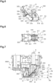
- this comprises a conductive element which delimits, on the one hand, a first place of insertion 110; 210; 310; 410; 610 intended to receive a connection pin 51 of the electrical plug 50 (shown on the Figure 4 ) to establish electrical contact between said connection pin 51 and the conductive element, and, on the other hand, a second insertion location 122; 222; 322; 422; 622, distinct from said first place of insertion 110; 210; 310; 410; 610, intended to receive an electrical conductor 2 coming from the network (such as the one shown on the figure 2 ) to establish electrical contact between the electrical conductor 2 and the conductive element.
- the first place of insertion 110; 210; 310; 410; 610 is a place where electrical contact is established between the connection pin 51 of the electrical plug 50 and the conductive element and it corresponds to the “receiving cell” 110; 210; 310; 410; 610 of female terminal 100; 200; 300; 400; 600.
- the second place of insertion 122; 222; 322; 422; 622 is a place where electrical contact is established between the stripped core of the electrical conductor 2 coming from the network and the conductive element.
- This second insertion location forms an electrical housing 122; 222; 322; 422; 622 for electrical conductor 2.
- the first and second places of insertion 110; 210; 310; 410; 610, 122; 222; 322; 422; 622 are formed within two distinct parts of the conductive element. These two distinct parts are electrically connected to each other: it is a functional part comprising the receiving cell 110; 210; 310; 410; 610, and an electrical connection part 120; 220; 320; 420; 620 comprising the electrical housing 122; 222; 322; 422; 622.
- the conductive element of the female terminal 100; 200; 300; 400; 600 is made of a metallic material which has satisfactory electrical conductivity to conduct current from the electrical connection part 120; 220; 320; 420; 620 to the receiving cell 110; 210; 310; 410; 610.
- the conductive element of the terminal is made of copper, or of a metal alloy containing copper, in particular brass or bronze.
- the conductive element is made in a single piece, by folding a metal strip 115; 215; 315; 415.
- the conductive element is formed into several parts mechanically and electrically connected to each other: here, one of the parts is terminated by a secondary connection pin 642 force-fitted into a secondary socket 640 provided on the other part.
- the receiving cell 110; 210; 310; 410; 610 is accessible from a first face of the female terminal, here the front face, via an inlet mouth delimited by a free edge 111; 211; 311; 411; 611 of said conductive element.
- the receiving cell 110; 210; 310; 410; 610 is generally cylindrical and extends along an axis
- the receiving cell is delimited between two branches 116; 216; 416; 616 with pliers 117; 217; 417; 617, articulated around an axis C1 (parallel to the axis and even confused) to the X axis.
- This clamp 117; 217; 417; 617 is formed by cutting and folding the metal strip 115; 215; 415; 615.
- the receiving cell 310 is delimited between two branches 316 of a U-shaped clamp 317, articulated around an axis C2 (perpendicular to the axis X), between which the connection pin of the plug is clamped electric introduced through the inlet mouth, in the direction of insertion coincident with the axis U-shaped, also called “jumper 318”, to which it is riveted.
- This jumper 318 surrounds the clamp 317 to guarantee that the clamping force of the branches 316 is constant over time, including after several insertions and withdrawals of the connection pin of the plug in this receiving socket 310.
- Electrical housing 122; 222; 322; 422; 622 is accessible from a second face of the female terminal opposite said first face, here the rear face, via an access opening delimited by an edge 125; 225; 325; 425; 625.
- the female terminal 100; 200; 300; 400; 600 rests with its rear face on the bottom wall 11;21;31; 41; 61 of the insulating base 10; 20; 30 ; 40; 60 of the socket mechanism 1000; 2000; 3000; 4000; 6000, at the corresponding location of this bottom wall 11;21;31; 41; 61 so that the access opening of its electrical housing 122; 222; 322; 422; 622 is placed opposite the entrance (or insertion opening) provided in said bottom wall 11; 21; 31; 41; 61 of the insulating base 10; 20; 30 ; 40; 60.
- the female terminal is electrically powered, from its rear face, by the insertion of the stripped core of the electrical conductor 2 (entering the insulating base via said entrance to the bottom wall) via the access opening in the electrical housing 122; 222; 322; 422; 622.
- An electrical contact is made in the electrical housing 122; 222; 322; 422; 622, downstream of this access opening, between the stripped core of the electrical conductor 2 and the conductive element of the female terminal 100; 200; 300; 400; 600.
- the conductive element carries electrical energy from the electrical conductor 2 to the connection pin 51 of the inserted electrical plug 50, from the front side from the female terminal, via the entry mouth into the receiving cell 110; 210; 310; 410; 610 of the conductive element.
- a first plane P1 which contains the edge 111; 211; 311; 411; 611 delimiting the entrance mouth in the reception cell 110; 210; 310; 410; 610, and which extends perpendicular to the axis X of extension of the receiving cell 110; 210; 310; 410; 610.
- a second plane P2 parallel to the first plane P1 and containing all or part of the edge 125; 225; 325; 425; 625 delimiting the access opening to the electrical housing 122; 222; 322; 422; 622.
- the first and second planes P1, P2 are located from one another at a distance D1 less than or equal to 9 millimeters (mm).
- the first and second planes P1, P2 are for example located at a distance of between 5 mm and 8 mm from each other.
- any other distance value D1 less than or equal to 9 mm can be considered.
- the first and second planes P1, P2 are separated from each other by a negative distance D1, that is to say that the second plane P2 is located in front of the first plane P1 (see Figure 13 ), the distance always being measured starting from the plane P1 (see direction of the arrow indicating the distance D1).
- the distance D1 separating the first and second planes P1, P2 is zero, that is to say that the first and second planes P1, P2 are combined 'one with the other.
- the offset of the second plane P2 towards the front of the female terminal 100; 200; 300; 400; 600 frees up space at the rear face of the female terminal 100; 200; 300; 400; 600.
- the offset of the second plane P2 forward, towards the first plane P1 results in the fact that the second plane P2 is offset forward relative to one end rear 112; 312; 612 of the receiving cell 110; 310; 610, opposite the entrance mouth.
- the shift of the second plane P2 forward, towards the first plane P1 results in the fact that the female electrical connection terminal 200 has a reduced overall height, here between 5 millimeters (mm) and 9 millimeters (mm), preferably between 5 and 8 millimeters.
- the female terminal 200 has on its rear face, facing the entry mouth into the receiving cell 210, an outlet opening from the receiving cell 210.
- the edge 212 delimiting the The outlet opening of the receiving cell is contained in the second plane P2.
- the standard connection pin 51 of the electrical plug 50 inserted in the female terminal 200 is then adapted to pass through the receiving recess 210, to come out through the outlet opening and to extend, towards the rear, at beyond female terminal 200.
- the location of the second plane P2 at the front of the first plane P1 results in the fact that the second plane P2 is offset forward relative to the mouth d entry into the receiving cell 410.
- This offset generates even more space on the side of the rear face of the female terminal 400, even if it is accompanied by a lateral distance of the electrical housing 433 relative to the central axis lateral dimensions of the female terminal 400.
- the stripped core of the electrical conductor 2 is inserted, via the access opening, into the electrical housing 122; 222; 322; 422; 622 of the female terminal, in an insertion direction Y (see figure 2 , 4 , 7 , 13 And 14 ) which can be inclined by an angle S less than or equal to 45° relative to an axis H perpendicular to the second plane P2, and passing through the center of the access opening.
- the direction of insertion Y of the stripped core of the electrical conductor in the electrical housing 122; 222; 322; 422; 622 of the terminal is not necessarily exactly parallel to the direction of insertion X of the connection pin 51 of the electrical plug 50 in the receiving recess 110; 210; 310; 410; 610 of this terminal, but it can be inclined by an angle, for example equal to 35° or even 45°, relative to said direction of insertion X.
- This arrangement facilitates the electrical connection of the female terminal 100; 200; 300; 400; 600, including in connection conditions in which the electrical conductors are relatively short and leave little room for maneuver. Indeed, the stripped core of the electrical conductor can thus be inserted into the electrical housing 122; 222; 322; 422; 622 with a low angle S relative to the axis of extension X of the cell, without this inclination compromising the electrical connection of the female terminal 100; 200; 300; 400; 600.
- the female terminal 100; 200; 300; 400; 600 includes means for clamping the stripped core against a conductive wall 121; 221; 321; 421; 621 (see figure 2 , 4 , 7 , 13 And 14 ) partially delimiting the electrical housing 122; 222; 322; 422; 622 of the connection part 120; 220; 320; 420; 620 of the female terminal.
- the female terminals shown are self-tightening terminals and the clamping means of each female terminal is formed by a leaf spring (not shown in the first embodiment) 230; 330; 430; 630 which permanently exerts a support force in the direction of said conductive wall 121; 221; 321; 421; 621.
- the stripped core of the electrical conductor 2 When the stripped core of the electrical conductor 2 is inserted into the electrical housing 122; 222; 322; 422; 622 via the access opening, it is automatically placed between the leaf spring 230; 330; 430; 630 and the conductive wall 121; 221; 321; 421; 621, so that the spring blade then presses the stripped core against said conductive wall 121; 221; 321; 421; 621.
- the blade springs 230; 330; 430; 630 is made of a metallic material, which may be distinct from that of the conductive element of the female terminal 100; 200; 300; 400; 600.
- a 150 disconnect stroller; 250; 350; 450 (not visible in the fifth embodiment of the female terminal 600 shown on the Figure 14 ) is mounted on the conductive element of the female terminal, to be able to disconnect the electrical conductor inserted in the electrical housing 122; 222; 322; 422; 622 of the female terminal.
- This disconnect stroller 150; 250; 350; 450 is made of insulating material, for example plastic. When it is engaged by a user or an installer, it exerts a disconnection force against the pressure force exerted by the leaf spring 230; 330; 430; 630.
- This disconnection force spreads the blade spring 230; 330; 430; 630 opposite the conductive wall 121; 221; 321; 421; 621, which allows the stripped core of the electrical conductor to be released from the pressure force exerted by the blade spring 230; 330; 430; 630. It is then possible to remove the stripped core from the electrical housing 122; 222; 322; 422; 622 in which it was inserted, via the access opening to said electrical housing, which electrically disconnects the female terminal 100; 200; 300; 400; 600.
- the conductive element of the female terminal 100; 200; 300; 400; 600 delimits a third insertion location (not visible in the second, fourth and fifth embodiments) 123; 323 intended to receive an electrical branching conductor to establish electrical contact between an electrical branching conductor and the conductive element of the female terminal (see figures 1 And 5 ).
- the third insertion location forms a second electrical housing 123; 323 similar to the first electrical housing 122; 222; 322; 422; 622 described previously.
- This second electrical housing 123; 323 is accessible from the rear face of female terminal 100; 200; 300; 400; 600, via a second access opening, distinct from the access opening to the first electrical housing 122; 222; 322; 422; 622, and delimited by an edge 126; 326 (not visible on the second, fourth and fifth embodiments). All or part of the edge 126; 326 delimiting said second access opening is, like edge 125; 225; 325; 425; 625, delimiting the first access opening to the first electrical housing 122; 222; 322; 422; 622, contained in the second plane P2.
- the stripped core of the electrical wiring conductor is clamped against a conductive wall delimiting the second electrical housing 123; 323 by means of a leaf spring similar to that used in the first electrical housing.
- the electrical connection part 120 of the female terminal 100 comprises two conduits, substantially cylindrical with parallel axes, forming the first and second electrical housings 122, 123 into which the stripped cores of the electrical conductors (the main conductor and the branching conductor) can be inserted.
- These conduits are delimited by parts of the metal strip 115 cut, curved and folded.
- Each curved part of the metal strip 115 forms the conductive wall 121 against which the stripped core inserted in the electrical housing 122, 123 is clamped by the spring blade.
- the rear free edge 125, 126 of the metal strip 115 thus curved defines, at the level of each conduit, the access opening to the electrical housing 122, 123.
- each electrical housing 122, 123 is further closed, at the front, by a wall 124, which prevents access to said electrical housings 122, 123 from the front of the female terminal 100.
- openings 128 are provided in a flat portion of the metal strip 115 to fix the spring blade.
- the spring blade can for example be formed by a metal ribbon folded so as to form an elbow which provides the spring function.
- Such a leaf spring is similar to the leaf spring 230 of the second embodiment of the female terminal 200 visible on the figure 4 .
- the electrical connection part 220 is in all respects similar to the electrical connection part 120 of the female terminal 100 according to the first embodiment, except that it is of lower height, the electrical connection part 220 being aligned, transversely, with the receiving cell 210.
- the electrical connection part 320 of the female terminal 300 is formed by a metal strip which extends from the base of the U-shaped clamp 317 whose branches 316 delimit the receiving cell 310.
- This strip metal presents, from where it is connected to the clamp 317, a portion 327 inclined relative to the axis direction of the mouth of the receiving cell 310 (that is to say facing towards the inside of the female terminal 300) and in which the access openings to the first and second electrical housings 322, 323 are provided Downstream of the first bump 328, the metal strip extends generally parallel to the axis the receiving cell 310 (that is to say facing outwards from the female terminal 300).
- Each of the first and second electrical housings 322, 323 is thus delimited by the first bump 328, the second bump 324 and the part of the metal strip extending between said first and second bumps 328, 324. It is against the second bump 324 which is intended to be established at least one electrical contact between the stripped core of the electrical conductor, introduced through the access opening, and the metal strip. This electrical contact is made thanks to the leaf spring 330.
- This leaf spring 330 extends, longitudinally, against the portion 327 of the metal strip by which the electrical connection part 320 is attached to the functional part comprising the receiving cell 310, as well as to the right of the part of the metal strip located between the first bump 328 and the second bump 324 (see Figure 7 ).
- the metal strip also includes means for connecting the leaf spring 330 to the metal strip. These means are here formed by folded tabs 331 to which the leaf spring 330 can for example be riveted, or in the form of pins around which corresponding openings in the leaf spring are anchored.
- the electrical connection part 420 is in every respect similar to that of the female terminal 300 according to the third embodiment except that the part of the conductive element delimiting the receiving cell 410 and the part of the the conductive element forming the portion 427 beyond which the bumps 428, 424 are formed, are connected to one another via an extension 440.
- This extension 440 is in one piece with the parts of the conductive element respectively forming the receiving cell 410 and the electrical connection part 420.
- the extension 440 extends perpendicular to the axis the reception cell 410, or even, as clearly shown in the Figure 13 , at a height chosen to be closer to the entry mouth into the receiving cell 410 than to a rear end 412 of said receiving cell 410. As shown in Figure 12 , this extension 440 is in further bent laterally to reduce, as much as possible, the distance separating the electrical housing 422 and the receiving cell 410 and therefore reduce the lateral bulk of the female terminal 400,
- the conductive element comprising the functional part forming the receiving cell 310; 410 and the electrical connection part 320; 420 is a one-piece piece.
- the receiving cell 610 is formed by a first part of the conductive element and the electrical connection part 620 is formed by a second part of the conductive element, separated from the first part.
- the electrical connection part 620 is in every respect similar to the electrical connection part 320 of the female terminal 300 according to the third embodiment, but the metal strip is terminated, beyond the second bump 624 by a secondary cell 640 connection.
- This secondary cell 640 is intended to receive by non-removable force engagement a secondary pin 642 carried by the part of the conductive element in which the receiving cell 610 is formed.
- the five embodiments of the power socket mechanism 1000; 2000; 3000; 4000; 6000 according to the invention comprise insulating bases 10; 20; 30 ; 40; 60, enclosing the female terminals 100; 200; 300; 400; 600 having just been described in detail, which are quite similar and which differ from each other essentially by their bottom wall 11; 21; 31; 41; 61 respectively.
- the bottom wall 11; 21; 31; 41; 61 of the insulating base 10; 20; 30 ; 40; 60 extends, at least at the level of the electrical connection part 120; 220; 320; 420; 620 of the terminal, and generally along the rear face of the female terminal 100; 200; 300; 400; 600 received in said insulating base 10; 20; 30 ; 40; 60.
- the entrance or insertion opening delimited by the edge 13; 23; 33; 43; 63, is provided in the bottom wall 11; 21; 31; 41; 61 of the insulating base, facing the access opening in the electrical housing 122; 222; 322; 422; 622 of said female terminal 100; 200; 300; 400; 600 corresponding, so as to allow the insertion of the stripped core of the electrical conductor 2 into the electrical housing, through the insulating base 10; 20; 30 ; 40; 60.
- edge 13; 23; 33; 43; 63 delimiting the insertion opening, on the side of the exterior face of the insulating base 10; 20; 30 ; 40; 60, is at least partly included in a third plane P3 parallel to the second plane P2 and separated from this second plane P2 by the thickness of the bottom wall 11; 21; 31. 41; 61 at which the insertion opening is provided.
- the thickness of the bottom wall 21; 31; 41 of base 20; 30 ; 40 is such that the insertion opening forms a real guide conduit 229; 329; 429 to insert the electrical conductor 2 into the electrical housing 222; 322; 422 of female terminal 100; 200; 300; 400 corresponding.
- the guide conduit 229; 329; 429 facilitates the insertion of the electrical conductor into the female terminal, without disturbing the natural curvature of the conductor.
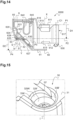
- the distance separating the second and third planes P2, P3, which corresponds to the thickness of the bottom wall to the right of the access opening to the electrical housing of the female terminals, is also standardized to guarantee that part of the insulating sheath of the electrical conductor penetrates into the bottom wall (see Figure 16 ). This ensures the electrical safety of the installer and protects the bare core which is entirely housed in the insulating base.
- the guide conduit 229; 329; 429 is cylindrical, and shaped to present a first section on the side of the exterior face of the bottom wall 21; 31; 41 of the insulating base 20; 30 ; 40, followed by a second section lower than the first section, on the side of the interior face of the bottom wall 21; 31; 41 of the insulating base 20; 30 ; 40.
- the first section is generally identical, except for clearance, to the section of the electrical conductor (insulating sheath and stripped core) used to power the female terminal 200; 300; 400 (see Figure 16 ), while the second section is generally identical, except for clearance, to the section of the conductive core of the electrical conductor (see Figure 16 ).
- the guide conduit 229; 329; 429 thus shaped with its two sections makes it possible to indicate to the installer the correct penetration of the electrical conductor into the terminal since the optimal penetration is reached when the insulating sheath surrounding the conductive core of the electrical conductor abuts against the second section of the guide conduit 229; 329; 429 (see Figure 16 ).
- a variant shape of the guide conduit is presented at the end of this description.
- a second entrance or insertion opening delimited by an edge 34; 44 (only visible on figures 9 , 10 and 11 ), is provided in the bottom wall 31; 41 of the insulating base 30; 40 opposite the second access opening in the second electrical housing of the terminal female (also called electrical wiring housing), to be able to insert the stripped core of the wiring conductor into this second electrical housing.
- This second insertion opening has the same properties as the first insertion opening.
- edge 34; 44 delimiting the second insertion opening, on the side of the exterior face of the bottom wall 31; 41 of the insulating base 30; 40 is at least partly included in the third plane P3 (see Figure 10 ).
- the second insertion opening also forms a guide conduit to reach the access opening of the electrical housing for transplanting the corresponding female terminal.
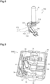
- the insulating base 10; 20; 30 ; 40; 60 is also designed to receive a male electrical connection terminal 700. Consequently, whatever the embodiment of the power socket mechanism 1000; 2000; 3000; 4000; 6000, but as shown more particularly in the Figure 10 representing the third embodiment of the socket mechanism 3000, in addition to the insertion openings provided in the bottom wall 31 of the insulating base 30 to provide access to the first electrical housing 322 and the second electrical housing 323 (or electrical housing transplanting 323) of each of the female terminals 300 received in said insulating base 30, there is also provided at least one insertion opening, delimited by an edge 36 to give access to an electrical housing 722 of the male terminal 700 (see figure 8 ).
- This electrical housing 722 is intended to receive the conductive core of an electrical earth conductor to connect said male terminal 700 to earth. In a manner similar to what is provided for the female terminals 300, there is also provided a insertion opening delimited by an edge 37 to provide access to an electrical housing for transplanting the male terminal 700.
- the profile of the bottom wall of the insulating base of this mechanism makes it possible to free up, to the right of the insertion openings, a space which, advantageously, will be useful to facilitate the wiring operation of the mechanism.
- This free space will be found in the electrical box 5 in which the power socket mechanism will be mounted, at the bottom of it, where the electrical conductors coming from the network arrive.
- This free space will advantageously serve to accommodate the curvature naturally adopted by each electrical conductor after its connection to the mechanism, curvature induced between its free end maintained in the terminal which it supplies and the rest of its length pushed into the bottom of the electrical box.
- the installer will thus be able, after having made the electrical connection of the mechanism, easily push the remaining length of said electrical conductors into the bottom of the electrical box, behind the insulating base, the electrical conductors being free to adopt their natural curvature in the free space located to the right of said insertion openings in the bottom wall of the base.
- the bottom wall 11; 31; 41; 61 of the insulating base 10; 30 ; 40; 60 includes a detached part 12; 32; 42; 62 towards the front of the insulating base 10; 30 ; 40; 60, towards the reception opening 15; 35; 45; 65 closed by the trim 8 of the power socket. It's in this unhooked part 12; 32; 42; 62 that the insertion openings are provided making it possible to reach the access openings to the electrical housing 122; 322; 422; 622; 722 of each female terminal 100; 300; 400; 600 and male 700.
- the third plane P3 in which all or part of the edges 13 are included; 33, 34, 36, 37; 43, 44; 63 delimiting the insertion openings is thus offset by a distance D2 relative to a fourth plane P4, parallel to the third plane P3 and containing the part of the bottom wall 11; 31; 41; 61 of the insulating base 10; 30 ; 40; 60 which is furthest (or furthest back) from the reception opening 15; 35; 45; 65 of said insulating base 10; 30 ; 40; 60 (see figure 2 , 7 , 13 And 14 ).
- the curved portion of the electrical conductor supplying the female terminal is thus housed in the free space delimited between the detached part 12; 32; 42; 62 and the rest of the bottom wall 11; 31; 41; 61 of the insulating base 10; 30 ; 40; 60.
- the curved part of the electrical conductor is housed in the overall volume of the insulating base.
- the distance D2 separating the third and fourth planes P3, P4 is at least 2 millimeters (mm), that is to say greater than or equal to 2 mm, preferably at least 5 mm.
- the configuration of the insulating base 30 shown on the Figure 10 in which all the insertion openings are provided in the same third plane P3, offset towards the front relative to the fourth plane P4, is possible thanks to a particular shape of the male terminal 700 according to the invention, shown on the figure 8 .
- This male terminal 700 comprises a conductive element 701 which, on the one hand, is connected to the earth pin 6, and which, on the other hand, delimits the electrical housing 722 intended to receive the electrical conductor to establish electrical contact between the electrical conductor and the conductive element 701. More precisely, the conductive element 701 forms, on the one hand, a platform 710 on which is crimped the earth pin 6 intended to project into the internal space of the insulating base 30 which will receive the hubcap 8 (see Figure 11 ), and, on the other hand, a metal strip similar in every respect to the electrical connection part 320; 420; 620 of female terminals 300; 400; 600 according to the third, fourth and sixth embodiments of the female terminal according to the invention.
- the electrical housing 722 delimited by this metal strip is accessible from the rear face of the male terminal 700, opposite the earth pin 6, via an access opening delimited by an edge 725 of the conductive element 701.
- the metal strip also delimits the electrical wiring housing (not visible on the figure 8 ), accessible via an access opening delimited by an edge (not visible on the figure 8 ) of the conductive element 701, to establish electrical contact between an electrical wiring conductor and the conductive element 701.
- the conductive core inserted into the electrical housing 722 or the wiring housing of the male terminal 700, via the corresponding access opening, is held in place by automatic tightening, by means of a blade spring 730.
- a disconnection stroller 350 ( Figure 10 ), similar to those described for the female terminals, makes it possible to act on the spring blade 730 when the male terminal 700 is in place in the insulating base 30, to disconnect the electrical conductor inserted in the electrical housing 722.
- the electrical housing 722 and the transplanting housing are offset towards the front, towards the platform 710 on which the earth pin 6 is fitted.
- a plane P'2 which is generally parallel to the platform 710 and which contains all or part of the edge 725 delimiting the access opening to the electrical housing 722 and all or part of the edge (not visible) delimiting the access opening to the transplanting housing.
- the bottom wall 31 of the insulating base 30 is designed to accommodate the male terminal 700 so that its plane P'2 aligns and merges with the second plane P2 of the female terminals 300 (see Figure 10 ).
- the plane P'2 is parallel to the third plane P3 and separated from said third plane P3 by the thickness of the bottom wall 31 of the insulating base 30.
- a passage opening, delimited by an edge 28, is provided in the bottom wall 21 of the insulating base 20, facing the outlet opening of the receiving cell 210 of the female terminal 200, so that the pin connection of an electrical plug inserted in said receiving cell 210 passes through said passage opening to extend, towards the rear, beyond the bottom wall 21 of the insulating base 20 (see Figure 4 ).
- the passage opening (delimited by the edge 28) of the bottom wall 21 is closed by a membrane 29 of deformable material (see Figure 4 ).
- the membrane 29 made of flexible insulating material is capable of deforming without breaking when the connection pin 51 of the electrical plug 50 exerts pressure on it (see Figure 4 ).
- the membrane 29 is made of flexible plastic material, so that it also has electrically insulating properties.
- the guide conduit formed by the insertion opening made in the bottom wall of the insulating base of the socket mechanism is shaped to further facilitate the delivery of the electrical conductor to the rear of the mechanism socket.
- the guide conduit 329' has a chamfered part 329A 'which extends obliquely relative to the central axis I of extension of said guide conduit 329' (see Figure 17 ), which central axis I of extension is perpendicular to the part of the bottom wall 31 of the insulating base 30 in which the guide conduit 329' is formed.
- the central axis I of extension of the guide conduit coincides with the axis H (see Figure 7 ) passing through the center of the access opening to the electrical housing of the connection terminal housed behind said insertion opening.
- the chamfered portion 329A' extends opposite the disconnection stroller associated with this insertion opening.
- the chamfered portion 329A' is here provided in the first section of the guide conduit 329' which is located on the side of the exterior face of the bottom wall 31 of the insulating base 30.
- This first section of the guide conduit 329' is thus oval shape, and of dimensions greater than those of the section of the electrical conductor 2.
- the edge 33' delimiting the insertion opening which forms this guide conduit 329', on the side of the external face of the bottom wall 31 of the insulating base 30, extends over two levels 33A ', 33B', which are here connected by a form of staircase (see Figure 15 ).
- the edge 33' delimiting the insertion opening comprises two parts 33A', 33B' offset relative to each other along the central axis I of extension of the guide conduit.
- the two levels 33A', 33B' of the edge 33' delimiting the insertion opening could very well be connected continuously, without breaking in the form of a staircase.
- the guide conduit 329' thus configured, with the chamfered portion 329A' and the external edge 33' which extends over two levels 33A', 33B' can accommodate a larger part of the curved portion 2A of the electrical conductor 2 (see Figure 17 ).
- the size of the electrical conductor 2 connected to the rear of the socket mechanism is thus reduced so that it is easier to insert into the electrical box intended to accommodate this mechanism.
- This advantageous configuration of the guide conduit 329' can of course be applied to any embodiment of the equipment mechanism described above, and to any insertion opening opening into a main electrical housing or for transplanting a male or female electrical connection terminal.
- this configuration of guide conduit is very advantageous because it saves space by partially housing the curved portion of electrical conductor.
- connection terminals female or male
- connection terminals could be screw terminals.
- the power outlet includes only two female electrical connection terminals and a ground connection bracket (Germanic type power outlet known as “Schuko”).
- the power outlet is of the type to be mounted projecting from a wall, by means of an electrical box to be fixed projecting from said wall.
Landscapes
- Connector Housings Or Holding Contact Members (AREA)
- Details Of Connecting Devices For Male And Female Coupling (AREA)
Claims (13)
- Steckdosenmechanismus (1000; 2000; 3000; 4000; 6000) mit einem isolierenden Sockel (10; 20; 30; 40; 60), der mindestens eine Verbindungsmuffe (100; 200; 300; 400; 600) mit mindestens einem Leitungselement aufnimmt, die einerseits einen ersten Einsteckort (110; 210; 310; 410; 610) abgrenzt, der dazu bestimmt ist, einen Verbindungsstift eines elektrischen Steckers aufzunehmen, um einen elektrischen Kontakt zwischen dem Verbindungsstift und dem Leitungselement herzustellen, und die andererseits einen vom ersten Einsteckort (110; 210; 310; 410; 610) verschiedenen zweiten Einsteckort (122; 222, 322, 422; 622) abgrenzt, der dazu bestimmt ist, einen elektrischen Leiter aufzunehmen, um einen elektrischen Kontakt zwischen dem elektrischen Leiter und dem Leitungselement herzustellen, wobei der erste Einsteckort (110; 210; 310; 410; 610) von einer ersten Seite der Muffe her über eine Eingangsmündung zugänglich ist, während der zweite Einsteckort (122; 222; 322; 422; 622) von einer von der ersten Seite abgewandten zweiten Seite der Muffe her über eine von der Mündung verschiedene Zugangsöffnung zugänglich ist, und wobei eine den die Eingangsmündung zum ersten Einsteckmechanismus (110; 210; 310; 410; 610) begrenzenden Rand (111; 211; 311; 411; 611) aufweisende und sich senkrecht zur Einführrichtung (X) des Verbindungsstifts in den ersten Einsteckort (110; 210; 310; 410; 610) erstreckende erste Ebene (P1) in einem Abstand (D1) von weniger als oder gleich 9 mm von einer zweiten Ebene (P2) erstreckt, die zur ersten Ebene (P1) parallel ist und das Ganze oder einen Teil des die Zugangsöffnung zum zweiten Einsteckort (122; 222; 322; 422; 622) begrenzenden Rands (125; 225; 325; 425; 625) aufweist, wobei der isolierende Sockel (10; 20; 30; 40; 60) vorne eine Aufnahmeöffnung (15; 35; 45; 65) einer Zierblende (8) einer Steckdose begrenzt und eine Basiswand (11; 21; 31; 41; 61) aufweist, die sich entlang wenigstens eines Teils der zweiten Seite der Muffe (100; 200; 300; 400; 600) erstreckt und die einen zur Aufnahmeöffnung (15; 35; 45; 65) hin abgesetzten Teil (12; 32; 42; 62) aufweist, in dem eine Einführöffnung gegenüber der Zugangsöffnung im zweiten Einsteckort (122; 222; 322; 422; 622) der Muffe (100; 200; 300; 400; 600) eingerichtet ist, wobei die Einführöffnung durch einen Rand (13; 23; 33; 43; 63) begrenzt ist, der mindestens teilweise in einer zur zweiten Ebene (P2) parallelen und von der zweiten Ebene (P2) durch die Dicke der Basiswand (11; 21; 31; 41; 61) getrennten dritten Ebene (P3) enthalten ist, wobei diese dritte Ebene (P3) in einer Entfernung (D2) von mindestens 2 mm von einer zur dritten Ebene (P3) parallelen vierten Ebene (P4) angeordnet ist und den von der Aufnahmeöffnung (15; 35; 45; 65) am weitesten entfernten Teil der Basiswand (11; 31; 41; 61) des isolierenden Sockels (10; 30; 40; 60) aufweist.
- Steckdosenmechanismus gemäß Anspruch 1, wobei die Muffe eine Höhe zwischen 5 mm und 9 mm hat und auf ihrer zweiten Seite, gegenüber der Eingangsmündung in den ersten Einsteckort (210), eine Ausgangsöffnung des ersten Einsteckorts (210) aufweist.
- Steckdosenmechanismus gemäß Anspruch 2, wobei der die Ausgangsöffnung des ersten Einsteckorts (210) der Muffe begrenzende Rand (212) in der zweiten Ebene (P2) enthalten ist.
- Steckdosenmechanismus gemäß einem der Ansprüche 1 bis 3, wobei die Einführrichtung (Y) des elektrischen Leiters in den zweiten Einsteckort (122; 222; 322; 422; 622) der Muffe über die Zugangsöffnung der Muffe um einen Winkel (S) von weniger als oder gleich 45° gegenüber einer zur zweiten Ebene (P2) senkrechten Achse (H) geneigt ist.
- Steckdosenmechanismus gemäß einem der Ansprüche 1 bis 4, wobei das Leiterelement der Muffe einen dritten Einsteckort (123; 323) abgrenzt, der dazu bestimmt ist, einen elektrischen Umsetzleiter aufzunehmen, um einen elektrischen Kontakt zwischen dem elektrischen Umsetzleiter und dem Leiterelement herzustellen, wobei der dritte Einsteckort (123; 323) von der zweiten Seite der Muffe (100; 200; 300; 400; 600) her über eine zweite, getrennte Zugangsöffnung zugänglich ist und wobei der gesamte Rand (126; 326) oder ein Teil davon, der die zweite Zugangsöffnung abgrenzt, in der zweiten Ebene (P2) enthalten ist.
- Steckdosenmechanismus gemäß einem der Ansprüche 1 bis 5, wobei das Leiterelement der Muffe teilweise durch ein Metallband gebildet ist, das einen Abschnitt (327; 427; 627) aufweist, der mit dem den ersten Einsteckort (310; 410; 610) begrenzenden Teil des elektrischen Leiters verbunden ist und auf den ein erster Buckel (328; 428; 628), dessen Hohlseite zur Eingangsmündung im ersten Einsteckort (310; 410; 10) gerichtet ist und in dem die Zugangsöffnung in den zweiten Einsteckort (322; 622) der Muffe gebildet ist, und ein zweiter Buckel (324; 424; 624), dessen Hohlseite entgegen der Eingangsmündung in den ersten Einsteckort (310; 410; 610) gerichtet ist und gegen die ein elektrischer Kontakt zwischen dem elektrischen Leiter und dem Metallband hergestellt werden soll, folgt.
- Steckdosenmechanismus (2000) gemäß einem der vorangehenden Ansprüche, wobei eine Durchgangsöffnung in der Basiswand (21) des isolierenden Sockels (20) gegenüber der Ausgangsöffnung des ersten Einsteckorts (210) der Muffe (200) eingerichtet ist.
- Steckdosenmechanismus (2000) gemäß Anspruch 7, wobei die Durchgangsöffnung mit einer Membrane (29) aus verformbarem und elektrisch isolierendem Material verschlossen ist.
- Steckdosenmechanismus (3000) gemäß einem der Ansprüche 1 bis 8, wobei die Basiswand (31) des isolierenden Sockels (30) mit einer Anzahl Einstecköffnungen versehen ist, die jeweils von Rändern (33, 34, 36, 37) begrenzt sind, die mindestens teilweise in der dritten Ebene (P3) enthalten sind, wobei eine der Einstecköffnungen Zugang zu einem elektrischen Verbindungsstift (700) gibt, der ein elektrisches Kontaktelement (6) aufweist, das in den Innenraum des isolierenden Sockels (30) hineinragt, der die Zierblende (8) aufnehmen soll.
- Steckdosenmechanismus (3000) gemäß Anspruch 9, wobei der elektrische Verbindungsstift (700) mindestens ein Leitungselement (701) aufweist, das einerseits mit dem elektrischen Kontaktelement (6) verbunden ist und das andererseits einen elektrischen Aufnahmeraum (722) begrenzt, der dazu bestimmt ist, einen elektrischen Leiter zum Herstellen eines elektrischen Kontakts zwischen dem elektrischen Leiter und dem Leitungselement (701) aufzunehmen, wobei der elektrische Aufnahmeraum (722) über eine Zugangsöffnung zugänglich ist, die im elektrischen Leitungselement (701) durch einen Rand (725) begrenzt ist, der mindestens teilweise in einer zur dritten Ebene (P3) parallelen und von der dritten Ebene (P3) durch die Dicke der Basiswand (31) des isolierenden Sockels (30) getrennten Ebene (P'2) enthalten ist.
- Steckdosenmechanismus (3000) gemäß einem der Ansprüche 1 bis 10, wobei mindestens eine der in der Basiswand (31) des isolierenden Sockels (30) vorgesehenen Einführöffnungen einen Führungskanal (329') bildet, von dem sich ein Teil (329A') gegenüber der zentralen Erstreckungsachse (1) des Führungskanals (329') schräg erstreckt.
- Steckdosenmechanismus (3000) gemäß Anspruch 11, wobei die Einführöffnung durch einen Rand begrenzt ist, der zwei entlang der zentralen Erstreckungsachse (1) gegeneinander versetzte Teile (33A', 33B') aufweist.
- Steckdose (1), die einerseits einen Geräteträger (3), der einen Steckdosenmechanismus (1000; 2000; 3000; 4000; 6000) gemäß einem der Ansprüche 1 bis 12 aufnimmt, und andererseits eine Zierblende (8), die einen Einführschacht (9) für einen elektrischen Stecker begrenzt, aufweist, wobei die Zierblende (8) eine Bodenwand (7) aufweist, die von Löchern durchbohrt ist, die zu den elektrischen Verbindungsmuffen (100; 200; 300; 400; 600) Zugang gewähren, die im isolierenden Sockel (10; 20; 30; 40; 60) des Steckdosenmechanismus (1000; 2000; 3000; 4000; 6000) angeordnet sind.
Applications Claiming Priority (1)
| Application Number | Priority Date | Filing Date | Title |
|---|---|---|---|
| FR2108474A FR3126067B1 (fr) | 2021-08-04 | 2021-08-04 | Borne femelle de connexion électrique pour prise de courant, mécanisme de prise de courant et prise de courant associés |
Publications (3)
| Publication Number | Publication Date |
|---|---|
| EP4131659A1 EP4131659A1 (de) | 2023-02-08 |
| EP4131659B1 true EP4131659B1 (de) | 2024-03-13 |
| EP4131659C0 EP4131659C0 (de) | 2024-03-13 |
Family
ID=78049380
Family Applications (1)
| Application Number | Title | Priority Date | Filing Date |
|---|---|---|---|
| EP22184068.9A Active EP4131659B1 (de) | 2021-08-04 | 2022-07-11 | Steckdosenmechanismus und entsprechende steckdose |
Country Status (3)
| Country | Link |
|---|---|
| EP (1) | EP4131659B1 (de) |
| CN (1) | CN115706353A (de) |
| FR (1) | FR3126067B1 (de) |
Family Cites Families (3)
| Publication number | Priority date | Publication date | Assignee | Title |
|---|---|---|---|---|
| JPS6022544Y2 (ja) * | 1979-10-12 | 1985-07-04 | 松下電工株式会社 | 配線器具 |
| DE3036545A1 (de) * | 1980-09-27 | 1982-05-27 | Fa. Albrecht Jung, 5885 Schalksmühle | Schutzkontaktsteckdose |
| FR3060873B1 (fr) * | 2016-12-15 | 2020-08-14 | Legrand France | Element de connexion electrique muni d’un element de contact |
-
2021
- 2021-08-04 FR FR2108474A patent/FR3126067B1/fr active Active
-
2022
- 2022-07-11 EP EP22184068.9A patent/EP4131659B1/de active Active
- 2022-07-27 CN CN202210890084.5A patent/CN115706353A/zh active Pending
Also Published As
| Publication number | Publication date |
|---|---|
| FR3126067A1 (fr) | 2023-02-10 |
| EP4131659A1 (de) | 2023-02-08 |
| FR3126067B1 (fr) | 2023-12-15 |
| EP4131659C0 (de) | 2024-03-13 |
| CN115706353A (zh) | 2023-02-17 |
Similar Documents
| Publication | Publication Date | Title |
|---|---|---|
| FR2857510A1 (fr) | Dispositif de connexion pour cable coaxial | |
| FR2936659A1 (fr) | Broche electrique integrant la cage d'une borne de connexion electrique automatique | |
| EP3657611B1 (de) | Stecker mit mehrfachausgängen | |
| FR2954604A1 (fr) | Borne de connexion electrique automatique et appareillage electrique comportant une telle borne | |
| EP3836315B1 (de) | Steckdose | |
| EP4131659B1 (de) | Steckdosenmechanismus und entsprechende steckdose | |
| EP1865578B1 (de) | Schneidklemm-Verbindungsanschluss eines isolierten elektrischen Leiters und elektrisches Gerät mit einem solchen Anschluss | |
| EP1655806A1 (de) | Verbinder, Sammelschienenadapter mit Verbinder und Verteilergehäuse mit Sammelschienenadapter und Verbinder | |
| EP3840136B1 (de) | Mechanismus eines elektrischen geräts, entsprechende elektrische anordung und entsprechendes elektrisches gerät | |
| EP1865579B1 (de) | Selbstabisolierende Verbindungsanschluss und elektrisches Gerät mit einem solchen Anschluss | |
| EP1147574B1 (de) | Koaxiale kabelverbindungseinrichtung | |
| FR3081085A1 (fr) | Boitier de securite electrique et de raccordement de cable(s) comportant un dispositif pyrotechnique et des fusibles | |
| EP1881561B1 (de) | Automatischer Anschluss mit einer Leitwand und elektrisches Gerät mit einem solchen Anschluss | |
| EP2843766B1 (de) | Elektrische Vorrichtung, die einen gedruckten elektrischen Schaltkreis auf einer Halterungsplatte und eine elektrische Anschlussklemme umfasst | |
| FR2936656A1 (fr) | Borne de connexion electrique automatique | |
| EP3255732B1 (de) | Elektrische verbindungsklemme, die einen verbindungshebel umfasst, und entsprechende elektrische geräte | |
| FR3020506A1 (fr) | Borne de connexion electrique multi-conducteurs | |
| EP2515390A1 (de) | Mehrfachgeräteblock, der mit Mitteln zur Befestigung an der Wand ausgestattet ist | |
| FR3060872A1 (fr) | Element de connexion electrique | |
| EP4376223A1 (de) | Anschlussleiste mit einem leiterrahmen und zugehörige elektrische reihenklemme | |
| EP3312948B1 (de) | Elektrische steckdose, die ein monoblockteil zur halterung und aufnahme von höckereinsätzen umfasst, und verfahren zum zusammenbau einer solchen elektrischen steckdose | |
| FR3135839A1 (fr) | Bornier électrique muni d’un élément mâle et d’un élément femelle de connexion électrique. | |
| EP3389141B1 (de) | Vorrichtung zur mechanischen halterung eines leitungsdrahtbündels | |
| FR3092945A1 (fr) | Dispositif de dérivation pour l’alimentation électrique d’une installation | |
| EP1172892A1 (de) | Verbindungsstecker und elektrischer Verbindungszusammenbau zwischen einem Sammelschienensystem und wenigstens einem leitenden Kabel |
Legal Events
| Date | Code | Title | Description |
|---|---|---|---|
| PUAI | Public reference made under article 153(3) epc to a published international application that has entered the european phase |
Free format text: ORIGINAL CODE: 0009012 |
|
| STAA | Information on the status of an ep patent application or granted ep patent |
Free format text: STATUS: THE APPLICATION HAS BEEN PUBLISHED |
|
| AK | Designated contracting states |
Kind code of ref document: A1 Designated state(s): AL AT BE BG CH CY CZ DE DK EE ES FI FR GB GR HR HU IE IS IT LI LT LU LV MC MK MT NL NO PL PT RO RS SE SI SK SM TR |
|
| STAA | Information on the status of an ep patent application or granted ep patent |
Free format text: STATUS: REQUEST FOR EXAMINATION WAS MADE |
|
| 17P | Request for examination filed |
Effective date: 20230704 |
|
| RBV | Designated contracting states (corrected) |
Designated state(s): AL AT BE BG CH CY CZ DE DK EE ES FI FR GB GR HR HU IE IS IT LI LT LU LV MC MK MT NL NO PL PT RO RS SE SI SK SM TR |
|
| GRAP | Despatch of communication of intention to grant a patent |
Free format text: ORIGINAL CODE: EPIDOSNIGR1 |
|
| STAA | Information on the status of an ep patent application or granted ep patent |
Free format text: STATUS: GRANT OF PATENT IS INTENDED |
|
| RIC1 | Information provided on ipc code assigned before grant |
Ipc: H01R 11/05 20060101ALN20231009BHEP Ipc: H01R 24/78 20110101ALN20231009BHEP Ipc: H01R 11/09 20060101ALN20231009BHEP Ipc: H01R 13/11 20060101ALI20231009BHEP Ipc: H01R 4/48 20060101AFI20231009BHEP |
|
| INTG | Intention to grant announced |
Effective date: 20231024 |
|
| GRAS | Grant fee paid |
Free format text: ORIGINAL CODE: EPIDOSNIGR3 |
|
| GRAA | (expected) grant |
Free format text: ORIGINAL CODE: 0009210 |
|
| STAA | Information on the status of an ep patent application or granted ep patent |
Free format text: STATUS: THE PATENT HAS BEEN GRANTED |
|
| AK | Designated contracting states |
Kind code of ref document: B1 Designated state(s): AL AT BE BG CH CY CZ DE DK EE ES FI FR GB GR HR HU IE IS IT LI LT LU LV MC MK MT NL NO PL PT RO RS SE SI SK SM TR |
|
| REG | Reference to a national code |
Ref country code: GB Ref legal event code: FG4D Free format text: NOT ENGLISH |
|
| REG | Reference to a national code |
Ref country code: CH Ref legal event code: EP |
|
| REG | Reference to a national code |
Ref country code: DE Ref legal event code: R096 Ref document number: 602022002340 Country of ref document: DE |
|
| REG | Reference to a national code |
Ref country code: IE Ref legal event code: FG4D Free format text: LANGUAGE OF EP DOCUMENT: FRENCH |
|
| U01 | Request for unitary effect filed |
Effective date: 20240318 |
|
| U07 | Unitary effect registered |
Designated state(s): AT BE BG DE DK EE FI FR IT LT LU LV MT NL PT SE SI Effective date: 20240325 |