EP4131584A1 - Batteriemodul mit wärmedämmelement - Google Patents
Batteriemodul mit wärmedämmelement Download PDFInfo
- Publication number
- EP4131584A1 EP4131584A1 EP21858529.7A EP21858529A EP4131584A1 EP 4131584 A1 EP4131584 A1 EP 4131584A1 EP 21858529 A EP21858529 A EP 21858529A EP 4131584 A1 EP4131584 A1 EP 4131584A1
- Authority
- EP
- European Patent Office
- Prior art keywords
- battery
- thermal insulation
- battery module
- battery cells
- insulation member
- Prior art date
- Legal status (The legal status is an assumption and is not a legal conclusion. Google has not performed a legal analysis and makes no representation as to the accuracy of the status listed.)
- Pending
Links
- 238000009413 insulation Methods 0.000 claims abstract description 56
- 239000004033 plastic Substances 0.000 claims abstract description 10
- 229920003023 plastic Polymers 0.000 claims abstract description 10
- 238000002844 melting Methods 0.000 claims abstract description 9
- 230000008018 melting Effects 0.000 claims abstract description 9
- 239000002131 composite material Substances 0.000 claims abstract description 7
- 239000003779 heat-resistant material Substances 0.000 claims abstract description 5
- 229910052751 metal Inorganic materials 0.000 claims description 8
- 239000002184 metal Substances 0.000 claims description 8
- 229920002647 polyamide Polymers 0.000 claims description 3
- -1 polypropylene Polymers 0.000 description 6
- 239000012774 insulation material Substances 0.000 description 5
- 238000001816 cooling Methods 0.000 description 4
- 230000002457 bidirectional effect Effects 0.000 description 3
- 239000000463 material Substances 0.000 description 3
- 239000007784 solid electrolyte Substances 0.000 description 3
- 239000000126 substance Substances 0.000 description 3
- 239000004743 Polypropylene Substances 0.000 description 2
- 239000011358 absorbing material Substances 0.000 description 2
- 230000008901 benefit Effects 0.000 description 2
- 230000000694 effects Effects 0.000 description 2
- 239000003792 electrolyte Substances 0.000 description 2
- 238000012986 modification Methods 0.000 description 2
- 230000004048 modification Effects 0.000 description 2
- 229920000642 polymer Polymers 0.000 description 2
- 229920001155 polypropylene Polymers 0.000 description 2
- WHXSMMKQMYFTQS-UHFFFAOYSA-N Lithium Chemical compound [Li] WHXSMMKQMYFTQS-UHFFFAOYSA-N 0.000 description 1
- HBBGRARXTFLTSG-UHFFFAOYSA-N Lithium ion Chemical compound [Li+] HBBGRARXTFLTSG-UHFFFAOYSA-N 0.000 description 1
- PXHVJJICTQNCMI-UHFFFAOYSA-N Nickel Chemical compound [Ni] PXHVJJICTQNCMI-UHFFFAOYSA-N 0.000 description 1
- 239000004677 Nylon Substances 0.000 description 1
- 239000004698 Polyethylene Substances 0.000 description 1
- 239000000654 additive Substances 0.000 description 1
- 230000000996 additive effect Effects 0.000 description 1
- 238000003915 air pollution Methods 0.000 description 1
- 229910052782 aluminium Inorganic materials 0.000 description 1
- XAGFODPZIPBFFR-UHFFFAOYSA-N aluminium Chemical compound [Al] XAGFODPZIPBFFR-UHFFFAOYSA-N 0.000 description 1
- 230000000712 assembly Effects 0.000 description 1
- 238000000429 assembly Methods 0.000 description 1
- 230000004888 barrier function Effects 0.000 description 1
- OJIJEKBXJYRIBZ-UHFFFAOYSA-N cadmium nickel Chemical compound [Ni].[Cd] OJIJEKBXJYRIBZ-UHFFFAOYSA-N 0.000 description 1
- 239000000919 ceramic Substances 0.000 description 1
- 239000008151 electrolyte solution Substances 0.000 description 1
- 238000004146 energy storage Methods 0.000 description 1
- 239000010408 film Substances 0.000 description 1
- 239000002803 fossil fuel Substances 0.000 description 1
- WABPQHHGFIMREM-NOHWODKXSA-N lead-200 Chemical compound [200Pb] WABPQHHGFIMREM-NOHWODKXSA-N 0.000 description 1
- 239000007788 liquid Substances 0.000 description 1
- 239000011244 liquid electrolyte Substances 0.000 description 1
- 229910052744 lithium Inorganic materials 0.000 description 1
- 229910001416 lithium ion Inorganic materials 0.000 description 1
- 238000004519 manufacturing process Methods 0.000 description 1
- 239000000155 melt Substances 0.000 description 1
- 229910000652 nickel hydride Inorganic materials 0.000 description 1
- QELJHCBNGDEXLD-UHFFFAOYSA-N nickel zinc Chemical compound [Ni].[Zn] QELJHCBNGDEXLD-UHFFFAOYSA-N 0.000 description 1
- 229920001778 nylon Polymers 0.000 description 1
- 230000000704 physical effect Effects 0.000 description 1
- 229920001748 polybutylene Polymers 0.000 description 1
- 229920000573 polyethylene Polymers 0.000 description 1
- 229920000139 polyethylene terephthalate Polymers 0.000 description 1
- 239000005020 polyethylene terephthalate Substances 0.000 description 1
- 229920001721 polyimide Polymers 0.000 description 1
- 239000009719 polyimide resin Substances 0.000 description 1
- 229920005672 polyolefin resin Polymers 0.000 description 1
- 229920005749 polyurethane resin Polymers 0.000 description 1
- 238000000926 separation method Methods 0.000 description 1
- 239000007787 solid Substances 0.000 description 1
- 239000000243 solution Substances 0.000 description 1
- 239000010409 thin film Substances 0.000 description 1
Images

Classifications
-
- H—ELECTRICITY
- H01—ELECTRIC ELEMENTS
- H01M—PROCESSES OR MEANS, e.g. BATTERIES, FOR THE DIRECT CONVERSION OF CHEMICAL ENERGY INTO ELECTRICAL ENERGY
- H01M10/00—Secondary cells; Manufacture thereof
- H01M10/60—Heating or cooling; Temperature control
- H01M10/65—Means for temperature control structurally associated with the cells
- H01M10/658—Means for temperature control structurally associated with the cells by thermal insulation or shielding
-
- H—ELECTRICITY
- H01—ELECTRIC ELEMENTS
- H01M—PROCESSES OR MEANS, e.g. BATTERIES, FOR THE DIRECT CONVERSION OF CHEMICAL ENERGY INTO ELECTRICAL ENERGY
- H01M10/00—Secondary cells; Manufacture thereof
- H01M10/60—Heating or cooling; Temperature control
- H01M10/61—Types of temperature control
- H01M10/613—Cooling or keeping cold
-
- H—ELECTRICITY
- H01—ELECTRIC ELEMENTS
- H01M—PROCESSES OR MEANS, e.g. BATTERIES, FOR THE DIRECT CONVERSION OF CHEMICAL ENERGY INTO ELECTRICAL ENERGY
- H01M10/00—Secondary cells; Manufacture thereof
- H01M10/60—Heating or cooling; Temperature control
- H01M10/64—Heating or cooling; Temperature control characterised by the shape of the cells
- H01M10/647—Prismatic or flat cells, e.g. pouch cells
-
- H—ELECTRICITY
- H01—ELECTRIC ELEMENTS
- H01M—PROCESSES OR MEANS, e.g. BATTERIES, FOR THE DIRECT CONVERSION OF CHEMICAL ENERGY INTO ELECTRICAL ENERGY
- H01M50/00—Constructional details or processes of manufacture of the non-active parts of electrochemical cells other than fuel cells, e.g. hybrid cells
- H01M50/20—Mountings; Secondary casings or frames; Racks, modules or packs; Suspension devices; Shock absorbers; Transport or carrying devices; Holders
- H01M50/204—Racks, modules or packs for multiple batteries or multiple cells
- H01M50/207—Racks, modules or packs for multiple batteries or multiple cells characterised by their shape
- H01M50/211—Racks, modules or packs for multiple batteries or multiple cells characterised by their shape adapted for pouch cells
-
- H—ELECTRICITY
- H01—ELECTRIC ELEMENTS
- H01M—PROCESSES OR MEANS, e.g. BATTERIES, FOR THE DIRECT CONVERSION OF CHEMICAL ENERGY INTO ELECTRICAL ENERGY
- H01M50/00—Constructional details or processes of manufacture of the non-active parts of electrochemical cells other than fuel cells, e.g. hybrid cells
- H01M50/20—Mountings; Secondary casings or frames; Racks, modules or packs; Suspension devices; Shock absorbers; Transport or carrying devices; Holders
- H01M50/233—Mountings; Secondary casings or frames; Racks, modules or packs; Suspension devices; Shock absorbers; Transport or carrying devices; Holders characterised by physical properties of casings or racks, e.g. dimensions
- H01M50/24—Mountings; Secondary casings or frames; Racks, modules or packs; Suspension devices; Shock absorbers; Transport or carrying devices; Holders characterised by physical properties of casings or racks, e.g. dimensions adapted for protecting batteries from their environment, e.g. from corrosion
-
- H—ELECTRICITY
- H01—ELECTRIC ELEMENTS
- H01M—PROCESSES OR MEANS, e.g. BATTERIES, FOR THE DIRECT CONVERSION OF CHEMICAL ENERGY INTO ELECTRICAL ENERGY
- H01M50/00—Constructional details or processes of manufacture of the non-active parts of electrochemical cells other than fuel cells, e.g. hybrid cells
- H01M50/20—Mountings; Secondary casings or frames; Racks, modules or packs; Suspension devices; Shock absorbers; Transport or carrying devices; Holders
- H01M50/289—Mountings; Secondary casings or frames; Racks, modules or packs; Suspension devices; Shock absorbers; Transport or carrying devices; Holders characterised by spacing elements or positioning means within frames, racks or packs
- H01M50/291—Mountings; Secondary casings or frames; Racks, modules or packs; Suspension devices; Shock absorbers; Transport or carrying devices; Holders characterised by spacing elements or positioning means within frames, racks or packs characterised by their shape
-
- H—ELECTRICITY
- H01—ELECTRIC ELEMENTS
- H01M—PROCESSES OR MEANS, e.g. BATTERIES, FOR THE DIRECT CONVERSION OF CHEMICAL ENERGY INTO ELECTRICAL ENERGY
- H01M50/00—Constructional details or processes of manufacture of the non-active parts of electrochemical cells other than fuel cells, e.g. hybrid cells
- H01M50/20—Mountings; Secondary casings or frames; Racks, modules or packs; Suspension devices; Shock absorbers; Transport or carrying devices; Holders
- H01M50/289—Mountings; Secondary casings or frames; Racks, modules or packs; Suspension devices; Shock absorbers; Transport or carrying devices; Holders characterised by spacing elements or positioning means within frames, racks or packs
- H01M50/293—Mountings; Secondary casings or frames; Racks, modules or packs; Suspension devices; Shock absorbers; Transport or carrying devices; Holders characterised by spacing elements or positioning means within frames, racks or packs characterised by the material
-
- H—ELECTRICITY
- H01—ELECTRIC ELEMENTS
- H01M—PROCESSES OR MEANS, e.g. BATTERIES, FOR THE DIRECT CONVERSION OF CHEMICAL ENERGY INTO ELECTRICAL ENERGY
- H01M50/00—Constructional details or processes of manufacture of the non-active parts of electrochemical cells other than fuel cells, e.g. hybrid cells
- H01M50/50—Current conducting connections for cells or batteries
- H01M50/502—Interconnectors for connecting terminals of adjacent batteries; Interconnectors for connecting cells outside a battery casing
- H01M50/505—Interconnectors for connecting terminals of adjacent batteries; Interconnectors for connecting cells outside a battery casing comprising a single busbar
-
- H—ELECTRICITY
- H01—ELECTRIC ELEMENTS
- H01M—PROCESSES OR MEANS, e.g. BATTERIES, FOR THE DIRECT CONVERSION OF CHEMICAL ENERGY INTO ELECTRICAL ENERGY
- H01M50/00—Constructional details or processes of manufacture of the non-active parts of electrochemical cells other than fuel cells, e.g. hybrid cells
- H01M50/50—Current conducting connections for cells or batteries
- H01M50/543—Terminals
- H01M50/547—Terminals characterised by the disposition of the terminals on the cells
- H01M50/548—Terminals characterised by the disposition of the terminals on the cells on opposite sides of the cell
-
- H—ELECTRICITY
- H01—ELECTRIC ELEMENTS
- H01M—PROCESSES OR MEANS, e.g. BATTERIES, FOR THE DIRECT CONVERSION OF CHEMICAL ENERGY INTO ELECTRICAL ENERGY
- H01M2200/00—Safety devices for primary or secondary batteries
- H01M2200/10—Temperature sensitive devices
-
- Y—GENERAL TAGGING OF NEW TECHNOLOGICAL DEVELOPMENTS; GENERAL TAGGING OF CROSS-SECTIONAL TECHNOLOGIES SPANNING OVER SEVERAL SECTIONS OF THE IPC; TECHNICAL SUBJECTS COVERED BY FORMER USPC CROSS-REFERENCE ART COLLECTIONS [XRACs] AND DIGESTS
- Y02—TECHNOLOGIES OR APPLICATIONS FOR MITIGATION OR ADAPTATION AGAINST CLIMATE CHANGE
- Y02E—REDUCTION OF GREENHOUSE GAS [GHG] EMISSIONS, RELATED TO ENERGY GENERATION, TRANSMISSION OR DISTRIBUTION
- Y02E60/00—Enabling technologies; Technologies with a potential or indirect contribution to GHG emissions mitigation
- Y02E60/10—Energy storage using batteries
Definitions
- the present invention relates to a battery module including a thermal insulation member having a composite structure capable of, even when thermal runaway occurs in a battery cell, preventing heat transfer to an adjacent battery cell.
- secondary batteries which are energy sources substituting for fossil fuels causing air pollution, have been applied to an electric vehicle (EV), a hybrid electric vehicle (HEV), a plug-in hybrid electric vehicle (P-HEV), and an energy storage system (ESS) .
- EV electric vehicle
- HEV hybrid electric vehicle
- P-HEV plug-in hybrid electric vehicle
- ESS energy storage system
- a lithium ion battery a lithium polymer battery, a nickel-cadmium battery, a nickel-hydride battery, and a nickel-zinc battery as secondary batteries that are widely used at present.
- the operating voltage of a unit secondary battery cell i.e. a unit battery cell, is about 2.0V to 5.0V.
- a plurality of battery cells may be connected to each other in series to constitute a battery cell assembly.
- battery cell assemblies may be connected to each other in series or in parallel to constitute a battery module depending on required output voltage or charge and discharge capacities.
- a battery pack is manufactured using at least one battery module by adding an additional component.
- the battery module is manufactured so as to have a structure in which the battery cells are disposed densely in the case in order to increase energy density thereof. When thermal runaway occurs in a specific battery cell, therefore, heat may be transferred to battery cells adjacent thereto.
- a thermal insulation material is provided between battery cells in order to prevent heat transfer between the battery cells and to prevent direct contact between the battery cells.
- the conventional thermal insulation material performs, for example, the function of a heat absorbing material having physical properties changed by heat generated when thermal runaway occurs in a battery cell, however, it is not possible to support battery cells and to interrupt heat transfer between the battery cells after thermal runaway occurs.
- a conventional thermal insulation material having a shape remaining unchanged after thermal runaway occurs is disposed in tight contact with a battery cell in which thermal runaway occurs.
- the present invention has been made in view of the above problems, and it is an object of the present invention to provide a battery module including a thermal insulation member having a composite structure capable of, even when thermal runaway occurs in a battery cell, preventing heat transfer to an adjacent battery cell and cooling the battery cell in which thermal runaway occurs.
- a battery module includes a plurality of battery cells, each battery cell of the plurality of battery cells having electrode leads, a case configured to receive the plurality of battery cells, and a thermal insulation member located between the plurality of battery cells, the thermal insulation member being configured to interrupt heat transfer between adjacent ones of the plurality of battery cells, wherein the thermal insulation member has a composite structure including an outer portion made of plastic having a lower melting point than temperature when thermal runaway occurs and a support member provided in an inner portion of the thermal insulation member, the support member being made of a heat-resistant material having a higher melting point than the temperature when the thermal runaway occurs.
- each of the plurality of battery cells may be a pouch-shaped battery cell having a structure in which two electrode leads, i.e. a positive electrode lead and a negative electrode lead, protrude in opposite directions.
- the case may include a lower case configured to receive the plurality of battery cells and the thermal insulation member and a cover located at the upper part of the lower case.
- the battery module according to the present invention may further include a busbar configured to electrically connect the electrode leads to each other.
- the thermal insulation member may be further provided between one of the plurality of battery cells and the case.
- the shape of the support member may be maintained even when the thermal runaway occurs to form an air layer between the plurality of battery cells.
- the support member may be made of one of metal and high heat-resistant polyamide-based plastic.
- the support member may have a plurality of protrusions formed on opposite surfaces of a thin plate.
- the support member may have rings which are joined to each other.
- a battery pack according to the present invention includes a battery module according to the present invention.
- a device according to the present invention includes a battery pack according to the present invention.
- a battery module according to the present invention has an advantage in that the battery module includes a thermal insulation member having a composite structure in which, when thermal runaway occurs in a battery cell, only a support member provided in the thermal insulation member remains unchanged to form an air layer between battery cells, whereby it is possible to maximize heat insulation and cooling effects while maintaining the distance between the battery cell in which thermal runaway occurs and battery cells adjacent thereto.
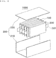
- FIG. 1 is an exploded perspective view of a battery module according to an embodiment of the present invention.
- the battery module 1000 includes a plurality of battery cells 100, each of which has electrode leads, a case 200 configured to receive the battery cells 100, and a thermal insulation member 300 located between the battery cells 100.
- each of the battery cells 100 may be a cylindrical battery cell, a prismatic battery cell, or a pouch-shaped battery cell.
- the battery module 1000 according to the present invention will be described with the focus on that the battery cell is a pouch-shaped battery cell 100.
- the pouch-shaped battery cell 100 includes a battery case having an electrode assembly received therein and a pair of electrode leads.
- the electrode assembly may be a jelly-roll type assembly, which is configured to have a structure in which a long sheet type positive electrode and a long sheet type negative electrode are wound in the state in which a separator is interposed therebetween, a stacked type electrode assembly, which is configured to have a structure in which a rectangular positive electrode and a rectangular negative electrode are stacked in the state in which a separator is interposed therebetween, a stacked and folded type assembly, which is configured to have a structure in which unit cells are wound using a long separation film, or a laminated and stacked type assembly, which is configured to have a structure in which unit cells are stacked in the state in which a separator is interposed therebetween and are then attached to each other.
- the present invention is not limited thereto.
- a solid electrolyte or a quasi-solid electrolyte manufactured by adding an additive to the solid electrolyte i.e. a gel-type electrolyte having an intermediate form between liquid and solid, may be used as an electrolyte, in addition to a liquid electrolyte, which is commonly used.
- the electrode assembly is received in the battery case, and the battery case is generally configured to have a laminate sheet structure including an inner layer, a metal layer, and an outer layer.
- the inner layer is disposed in direct contact with the electrode assembly, and therefore the inner layer must exhibit high insulation properties and high resistance to an electrolytic solution.
- the inner layer must exhibit high sealability in order to hermetically seal the battery case from the outside, i.e. a thermally-bonded sealed portion between inner layers must exhibit excellent thermal bonding strength.
- the inner layer may be made of a material selected from among a polyolefin-based resin, such as polypropylene, polyethylene, polyethylene acrylate, or polybutylene, a polyurethane resin, and a polyimide resin, which exhibit excellent chemical resistance and high sealability.
- a polyolefin-based resin such as polypropylene, polyethylene, polyethylene acrylate, or polybutylene, a polyurethane resin, and a polyimide resin, which exhibit excellent chemical resistance and high sealability.
- polypropylene which exhibits excellent mechanical-physical properties, such as tensile strength, rigidity, surface hardness, and impact resistance strength, and excellent chemical resistance, is the most preferably used.
- the metal layer which is disposed so as to abut the inner layer, corresponds to a barrier layer configured to prevent moisture or various kinds of gas from permeating into the battery from the outside.
- An aluminum thin film which is light and easily shapeable, may be used as a preferred material for the metal layer.
- the outer layer is provided on the other surface of the metal layer.
- the outer layer may be made of a heat-resistant polymer that exhibits excellent tensile strength, resistance to moisture permeation, and resistance to air permeation such that the outer layer exhibits high heat resistance and chemical resistance while protecting the electrode assembly.
- the outer layer may be made of nylon or polyethylene terephthalate.
- the present invention is not limited thereto.
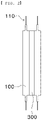
- the pair of electrode leads 110 is constituted by a positive electrode lead and a negative electrode lead, which may be exposed from the battery case in a state of being electrically connected respectively to positive electrode tabs and negative electrode tabs of the cell assembly or may be directly connected to the cell assembly in the state in which tabs are omitted.
- the pouch-shaped battery cell 100 may be a unidirectional lead cell having a structure in which the electrode leads 110, i.e., the positive electrode lead and the negative electrode lead, protrude in the same direction or a bidirectional lead cell having a structure in which the positive electrode lead and the negative electrode lead protrude in opposite directions.
- the battery cell 100 according to the present invention is a pouch-shaped battery cell 100 having the structure of a bidirectional lead cell 100.
- the bidirectional lead cell 100 is generally longer in a direction in which the leads protrude than the unidirectional lead cell, and a member configured to support the battery cell 100 when the battery cell is received in the module is necessary due to the increased length thereof.
- the case 200 includes a lower case 210 configured to receive the battery cells 100 and the thermal insulation member 300 and a cover 220 located at the upper part of the lower case 210, the cover being configured to cover the upper part of the lower case after the battery cells 100 and the thermal insulation member 300 are received in the lower case.
- the battery module 1000 may further include various other components, such as a busbar configured to electrically connect the electrode leads to each other and a sensing board configured to sense voltage information of the battery cells.
- a busbar configured to electrically connect the electrode leads to each other
- a sensing board configured to sense voltage information of the battery cells.
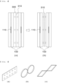
- FIG. 2 is a plan view showing a thermal insulation member located between the battery cells in the battery module according to the embodiment of the present invention
- FIG. 3 is a plan view showing a thermal insulation member located between the battery cell and the case in the battery module according to the embodiment of the present invention.
- the thermal insulation member 300 may be located between one of the battery cells 100 and another battery cell 100, or may be located between one of the battery cells 100 and another battery cell 100 and between each of the outermost battery cells 100 and a corresponding one of the side surfaces of the lower case 210, in which the battery cells are received.
- the thermal insulation member 300 may serve to insulate the battery cells 100 from each other while supporting the battery cells at a normal temperature, and may serve to prevent heat transfer between the battery cells 100 when thermal runaway occurs in any one of the battery cells.
- the shape of the thermal insulation member 300 is not particularly restricted, it is preferable for the thermal insulation member 300 to be formed so as to be disposed in tight contact with the side surface of the battery cell 100 that abut the thermal insulation member in consideration of energy density of the battery module 1000.
- the area of the side surface of the thermal insulation member 300 is shown as being equal to the area of the side surface of the portion of the battery cell 100 in which the electrode is received.
- the area of the side surface of the thermal insulation member 300 is not limited thereto and may be variously selected within a range in which the thermal insulation member 300 is capable of performing the function described in the present invention and the thermal insulation member does not interfere with other components of the battery module 1000.
- FIG. 4 is a front view showing shapes of a thermal insulation member according to an embodiment of the present invention before and after thermal runaway
- FIG. 5 is a perspective view showing various shapes of a support member according to an embodiment of the present invention.
- the thermal insulation member 300 is configured to have a composite structure including an outer portion made of plastic having a lower melting point than temperature when thermal runaway occurs and a support member 310 provided in an inner portion of the thermal insulation member, the support member being made of a heat-resistant material having a higher melting point than temperature when thermal runaway occurs.
- FIG. 5 shows a structure in which protrusions are formed on a thin plate, a structure in which thin bands each having a predetermined width are connected to each other in ring shapes, or a structure in which thin bands each having a predetermined width are connected to each other in quadrangular shapes as an example of the shape of the support member 310
- the support member 310 may be formed so as to have various shapes as long as the area of contact between the support member and the battery cell 100 is as small as possible within a range capable of supporting the battery cells 100.
- the structure in which the area of contact between the support member 310 and the battery cell 100 is as small as possible is advantageous in the aspect of thermal insulation.
- the support member 310 may be made of any of various well-known materials, such as metal, ceramics, and high heat-resistant plastic, as a heat-resistant material having a higher melting point than temperature when thermal runaway occurs. In consideration of ease and cost in manufacture of the support member 310 and the thermal insulation member 300 including the support member 310, however, it is preferable for the support member to be made of one of metal and high heat-resistant polyamide-based plastic.
- plastic constituting the outer portion of the thermal insulation member 300 having the support member 310 therein remains unchanged, whereby the thermal insulation member is disposed in tight contact with the battery cell 100 adjacent thereto over a large area.
- plastic constituting the outer portion of the thermal insulation member melts, whereby only the support member 310 provided in the thermal insulation member is left to support the battery cell 100 adjacent thereto over the minimum area.
- an air layer is formed between the battery cells 100 or between the battery cell 100 and the case 200, whereby thermal insulation performance may be improved.
- heat generated as the result of thermal runaway is discharged to the outside through convection in the air layer, whereby the function of cooling the battery cell 100 in which thermal runaway occurs may also be performed at the same time.
- the support member 310 according to the present invention is different from a conventional thermal insulation member in that the support member supports the battery cell 100 with the minimum contact area and the air layer that performs thermal insulation and cooling functions is formed between the battery cells 100 when thermal runaway occurs, unlike the conventional thermal insulation material, which performs the function of a thermal insulation material that interrupts heat transfer when thermal runaway occurs or performs the function of an absorbing material that absorbs heat.
Landscapes
- Chemical & Material Sciences (AREA)
- Chemical Kinetics & Catalysis (AREA)
- Electrochemistry (AREA)
- General Chemical & Material Sciences (AREA)
- Engineering & Computer Science (AREA)
- Manufacturing & Machinery (AREA)
- Battery Mounting, Suspending (AREA)
- Secondary Cells (AREA)
- Sealing Battery Cases Or Jackets (AREA)
- Connection Of Batteries Or Terminals (AREA)
Applications Claiming Priority (2)
| Application Number | Priority Date | Filing Date | Title |
|---|---|---|---|
| KR1020200104768A KR20220023191A (ko) | 2020-08-20 | 2020-08-20 | 단열 부재를 포함하는 배터리 모듈 |
| PCT/KR2021/010732 WO2022039442A1 (ko) | 2020-08-20 | 2021-08-12 | 단열 부재를 포함하는 배터리 모듈 |
Publications (1)
| Publication Number | Publication Date |
|---|---|
| EP4131584A1 true EP4131584A1 (de) | 2023-02-08 |
Family
ID=80323578
Family Applications (1)
| Application Number | Title | Priority Date | Filing Date |
|---|---|---|---|
| EP21858529.7A Pending EP4131584A1 (de) | 2020-08-20 | 2021-08-12 | Batteriemodul mit wärmedämmelement |
Country Status (6)
| Country | Link |
|---|---|
| US (1) | US20230178824A1 (de) |
| EP (1) | EP4131584A1 (de) |
| JP (1) | JP2023524706A (de) |
| KR (1) | KR20220023191A (de) |
| CN (1) | CN115485911A (de) |
| WO (1) | WO2022039442A1 (de) |
Families Citing this family (2)
| Publication number | Priority date | Publication date | Assignee | Title |
|---|---|---|---|---|
| WO2023210931A1 (ko) * | 2022-04-25 | 2023-11-02 | 주식회사 엘지에너지솔루션 | 배터리 모듈, 배터리 팩 및 이를 포함하는 자동차 |
| KR20240031474A (ko) * | 2022-08-29 | 2024-03-08 | 주식회사 엘지에너지솔루션 | 안전성이 향상된 배터리 팩 |
Family Cites Families (6)
| Publication number | Priority date | Publication date | Assignee | Title |
|---|---|---|---|---|
| US7736799B1 (en) * | 2009-07-17 | 2010-06-15 | Tesla Motors, Inc. | Method and apparatus for maintaining cell wall integrity during thermal runaway using an outer layer of intumescent material |
| WO2012060558A2 (ko) * | 2010-11-05 | 2012-05-10 | 주식회사 엘지화학 | 안전성이 향상된 이차전지 |
| JP2012124319A (ja) * | 2010-12-08 | 2012-06-28 | Jm Energy Corp | 蓄電デバイス |
| JP5486623B2 (ja) * | 2012-03-09 | 2014-05-07 | 豊田合成株式会社 | 電池ホルダ |
| EP3327817B1 (de) * | 2016-11-29 | 2019-11-06 | Samsung SDI Co., Ltd. | Wandstruktur einer batteriezelle, batterieuntermodul, batteriemodul oder batteriesystem |
| DE102019202560A1 (de) | 2019-02-26 | 2020-08-27 | Hyundai Motor Company | System und verfahren zur abgasnachbehandlung, fahrzeug und verfahren zum betreiben eines fahrzeugs |
-
2020
- 2020-08-20 KR KR1020200104768A patent/KR20220023191A/ko active Search and Examination
-
2021
- 2021-08-12 CN CN202180031538.7A patent/CN115485911A/zh active Pending
- 2021-08-12 WO PCT/KR2021/010732 patent/WO2022039442A1/ko unknown
- 2021-08-12 US US17/921,857 patent/US20230178824A1/en active Pending
- 2021-08-12 EP EP21858529.7A patent/EP4131584A1/de active Pending
- 2021-08-12 JP JP2022566246A patent/JP2023524706A/ja active Pending
Also Published As
| Publication number | Publication date |
|---|---|
| CN115485911A (zh) | 2022-12-16 |
| WO2022039442A1 (ko) | 2022-02-24 |
| US20230178824A1 (en) | 2023-06-08 |
| JP2023524706A (ja) | 2023-06-13 |
| KR20220023191A (ko) | 2022-03-02 |
Similar Documents
| Publication | Publication Date | Title |
|---|---|---|
| US20220263174A1 (en) | Battery module capable of preventing movement of gas to adjacent module | |
| EP4131584A1 (de) | Batteriemodul mit wärmedämmelement | |
| US20190280263A1 (en) | Safety-improved Battery Cell Including Thermal Expansion Tape and Method of Manufacturing Same | |
| US20230170557A1 (en) | Battery module having fire transition prevention structure and battery pack including the same | |
| KR20090077135A (ko) | 슬림형 이차전지 | |
| KR20210009795A (ko) | 전류 차단 기능이 구비된 전지 모듈 및 이를 포함하는 디바이스 | |
| KR101404707B1 (ko) | 외부로 돌출된 전압검출용 단자를 포함하는 셀 어셈블리 | |
| KR20210107416A (ko) | 퇴화방지구조를 갖는 배터리 모듈 및 이를 포함하는 배터리 팩 | |
| KR20210003607A (ko) | 밀착형 쿨링플레이트를 포함하는 배터리 팩 및 이를 포함하는 디바이스 | |
| KR20220005221A (ko) | 접착부재에 의해 전극 리드와 버스바가 연결된 전지 모듈 | |
| EP4250449A1 (de) | Beutelartige batteriezelle mit verbesserter sicherheit und batteriemodul damit | |
| EP4191750A1 (de) | Batteriepack mit verbesserter kühlleistung sowie vorrichtung damit | |
| EP4210162A1 (de) | Beutelartige batteriezelle mit sicherheitselement zwischen elektrodenleitung und leitungsfilm | |
| EP4224596A1 (de) | Batteriemodul mit funktion zur erkennung von elektrolytleckagen und batteriepack damit | |
| EP4243194A1 (de) | Beutelartige batteriezelle mit verbesserter thermischer stabilität | |
| US20230198106A1 (en) | Battery Cell Including Electrode Tab Having Stress Relief Portion | |
| EP4120446A1 (de) | Sekundärbatterie | |
| KR20230071572A (ko) | 냉각 기능이 향상된 전지 스택 및 이를 포함하는 전지 모듈 | |
| KR20220039437A (ko) | 균일한 온도 분포를 갖는 전지 모듈 및 이의 제조방법 | |
| KR20220036236A (ko) | 상이한 두께의 전극 리드를 구비한 배터리 셀을 포함하는 배터리 모듈 | |
| KR20220014723A (ko) | 냉각핀과 냉각 튜브를 구비한 배터리 셀 어셈블리 | |
| KR20220168363A (ko) | 이차 전지 | |
| KR20230049453A (ko) | 이차 전지 및 이를 포함하는 전지 모듈 |
Legal Events
| Date | Code | Title | Description |
|---|---|---|---|
| STAA | Information on the status of an ep patent application or granted ep patent |
Free format text: STATUS: THE INTERNATIONAL PUBLICATION HAS BEEN MADE |
|
| PUAI | Public reference made under article 153(3) epc to a published international application that has entered the european phase |
Free format text: ORIGINAL CODE: 0009012 |
|
| STAA | Information on the status of an ep patent application or granted ep patent |
Free format text: STATUS: REQUEST FOR EXAMINATION WAS MADE |
|
| 17P | Request for examination filed |
Effective date: 20221104 |
|
| AK | Designated contracting states |
Kind code of ref document: A1 Designated state(s): AL AT BE BG CH CY CZ DE DK EE ES FI FR GB GR HR HU IE IS IT LI LT LU LV MC MK MT NL NO PL PT RO RS SE SI SK SM TR |
|
| DAV | Request for validation of the european patent (deleted) | ||
| DAX | Request for extension of the european patent (deleted) |