EP4130596A1 - Zentrale verwaltungsvorrichtung für eine klimaanlage und zeitkorrekturverfahren - Google Patents
Zentrale verwaltungsvorrichtung für eine klimaanlage und zeitkorrekturverfahren Download PDFInfo
- Publication number
- EP4130596A1 EP4130596A1 EP20926417.5A EP20926417A EP4130596A1 EP 4130596 A1 EP4130596 A1 EP 4130596A1 EP 20926417 A EP20926417 A EP 20926417A EP 4130596 A1 EP4130596 A1 EP 4130596A1
- Authority
- EP
- European Patent Office
- Prior art keywords
- time
- clock
- built
- remote controller
- time correction
- Prior art date
- Legal status (The legal status is an assumption and is not a legal conclusion. Google has not performed a legal analysis and makes no representation as to the accuracy of the status listed.)
- Pending
Links
Images




Classifications
-
- F—MECHANICAL ENGINEERING; LIGHTING; HEATING; WEAPONS; BLASTING
- F24—HEATING; RANGES; VENTILATING
- F24F—AIR-CONDITIONING; AIR-HUMIDIFICATION; VENTILATION; USE OF AIR CURRENTS FOR SCREENING
- F24F11/00—Control or safety arrangements
- F24F11/50—Control or safety arrangements characterised by user interfaces or communication
- F24F11/61—Control or safety arrangements characterised by user interfaces or communication using timers
-
- F—MECHANICAL ENGINEERING; LIGHTING; HEATING; WEAPONS; BLASTING
- F24—HEATING; RANGES; VENTILATING
- F24F—AIR-CONDITIONING; AIR-HUMIDIFICATION; VENTILATION; USE OF AIR CURRENTS FOR SCREENING
- F24F11/00—Control or safety arrangements
- F24F11/50—Control or safety arrangements characterised by user interfaces or communication
- F24F11/56—Remote control
-
- G—PHYSICS
- G08—SIGNALLING
- G08C—TRANSMISSION SYSTEMS FOR MEASURED VALUES, CONTROL OR SIMILAR SIGNALS
- G08C17/00—Arrangements for transmitting signals characterised by the use of a wireless electrical link
Definitions
- Embodiments of the present invention relate to a central control device and a time correction method of an air conditioning system.
- each remote controller of each indoor unit has a built-in clock and a timer function.
- the timer function is performed based on a clocked time of the clock.
- a user uses one of the remote controllers to perform a timer setting operation such that an operation of the corresponding indoor unit starts at a prescribed time, for example.
- the remote controller monitors whether the time has arrived based on clocking performed by the built-in clock, and transmits an operation start instruction to the connected indoor unit when the remote controller determines that the time has arrived.
- the built-in clocks of the plurality of remote controllers in the air conditioning system are individually and separately performing clocking operations, and as time passes, a time deviation from the correct time gradually occurs.
- a higher order central control device of a plurality of air conditioning systems is provided, and a built-in clock of each air conditioning system is corrected by using the time of an internal clock of the central control device as a standard time.
- Patent Literature 1 Japanese Unexamined Patent Application Publication No. Hei 01-265398
- the time correction process is performed on the remote controllers or the like in the air conditioning system as described above, if a delay occurs in a built-in clock to be corrected, by performing the time correction process, the clocked time is shifted forward by a prescribed period. Therefore, a blank period during which no clocking is performed by the built-in clock occurs.
- the remote controller if a timer relating to any operation is set by using a time in the blank period as an execution time, the corresponding operation is not executed because the time in the blank period is not clocked.
- the built-in clock of the remote controller is clocking 11:59:50 which is 10 seconds later than the standard time and an instruction for correcting the time to 12:00:00 is acquired by means of the time correction process.
- the clocked time of the built-in clock changes to 12:00:00. This means the time period from immediately after 11:59:50 to 12:00 becomes a blank period.
- the time may fall in the blank period of the built-in clock and not be counted, and the operation may not be started.
- a clocked time of a built-in clock to be corrected is advanced, and by performing the time correction process, the clocked time is shifted backward by a prescribed period.
- an overlapping period during which clocking is performed twice by means of the built-in clock occurs.
- a timer relating to any operation is set by using a time in the overlapping period as an execution time. In this case, even if the operation performed by means of the timer function when the time is clocked for the first time is canceled immediately thereafter by means of a user operation or the like, the operation is performed again by means of the timer function when the time is clocked for the second time, which may cause inconvenience to the user.
- the built-in clock of the remote controller clocks 12:00:20 which is 20 seconds ahead of the standard time
- an instruction for correcting the time to 12:00:00 is acquired by means of the time correction process.
- the clocked time of the built-in clock changes to 12:00:00, and thus the time period from 12:00 to 12:00:20 becomes an overlapping period.
- the operation of the corresponding indoor unit is started by means of the timer function when 12:00 is clocked for the first time (before performing the time correction process).
- the clocked time changes from 12:00:20 to 12:00 due to the time correction process.
- the present invention has been devised in view of the above described problems, and an object of the present invention is to provide a central control device and a time correction method of an air conditioning system which perform a time correction process for clocks built into equipment in an air conditioning system while appropriately operating the equipment.
- a central control device in an air conditioning system in accordance with the present invention is communicatively connected to a remote controller including a remote controller built-in clock and including a timer function based on clocking performed by the remote controller built-in clock, the central control device including: a central built-in clock configured to clock a time; a time correction timing setter in which time correction timing information indicating a time other than a time in which a ones place value of a minutes unit is "0" or "5" is set as a timing at which a time correction process of the remote controller built-in clock is performed; and a time correction processor configured to, upon determining that the time of the central built-in clock has reached the time indicated by the time correction timing information set in the time correction timing setter, transmits a correction instruction for correcting a clocked time of the remote controller built-in clock to a corresponding time, to the remote controller.
- a time correction method of an air conditioning system in accordance with the present invention includes: using a central control device that is communicatively connected to a remote controller including a remote controller built-in clock and including a timer function based on clocking performed by the remote controller built-in clock, and includes a central built-in clock configured to clock a time, setting time correction timing information indicating a time other than a time in which a ones place value of a minutes unit is "0" or "5", as a timing at which a time correction process of the remote controller built-in clock is performed; and upon determining that the time of the central built-in clock has reached the time indicated by the set time correction timing information, transmitting a correction instruction for correcting a clocked time of the remote controller built-in clock to the time of the central built-in clock, to the remote controller.
- An air conditioning system 1A includes an outdoor unit 10 installed in a prescribed building, a plurality of indoor units (a first indoor unit 20a, a second indoor unit 20b, and a third indoor unit 20c) connected to the outdoor unit 10 by using refrigerant piping and communication lines, a plurality of remote controllers (a first remote controller 30a, a second remote controller 30b, and a third remote controller 30c) that are respectively communicatively connected to the indoor units, and a system controller 40 as the central control device connected to the outdoor unit 10.
- a plurality of indoor units a first indoor unit 20a, a second indoor unit 20b, and a third indoor unit 20c
- a plurality of remote controllers a first remote controller 30a, a second remote controller 30b, and a third remote controller 30c
- the case is described in which the number of indoor units connected to the outdoor unit 10 and the number of remote controllers are three. However, more than three indoor units and remote controllers may be connected.
- indoor units are referred to as an indoor units 20.
- remote controllers 30a, 30b, and 30c remote controllers 30.
- the outdoor unit 10 includes an outdoor unit built-in clock 11, an outdoor unit-indoor unit communicator 12, an outdoor unit-central communicator 13, and an outdoor unit operation control unit 14.
- the outdoor unit-indoor unit communicator 12 communicates with each of the indoor unit 20a, 20b, and 20c.
- the outdoor unit-central communicator 13 communicates with the system controller 40.
- the outdoor unit operation control unit 14 controls, based on an instruction transmitted from the system controller 40, operations of the equipment in the outdoor unit 10 including time correction process of the outdoor unit built-in clock 11.
- the outdoor unit operation control unit 14 transfers the instruction to the corresponding indoor unit 20.
- the first indoor unit 20a includes an indoor unit built-in clock 21, an indoor unit-remote controller communicator 22, an indoor unit-outdoor unit communicator 23, and an indoor unit operation control unit 24.
- the indoor unit-remote controller communicator 22 communicates with the corresponding first remote controller 30a.
- the indoor unit-outdoor unit communicator 23 communicates with the outdoor unit 10.
- the indoor unit operation control unit 24 controls the operation of the equipment in the indoor unit 20a based on the instruction which is transmitted from the system controller 40 and then transferred by means of the outdoor unit 10 and the instruction transmitted from the first remote controller 30a connected to the indoor unit. After the indoor unit operation control unit 24 receives the time correction instruction transmitted from the system controller 40, the indoor unit operation control unit 24 transfers the instruction to the first remote controller 30a connected to the indoor unit.
- the second indoor unit 20b and the third indoor unit 20c have the same configuration as the first indoor unit 20a, a detailed description thereof will be omitted.
- the first remote controller 30a includes a remote controller-indoor unit communicator 31, an operation input unit 32, a remote controller built-in clock 33, a timer setter 34, a time correction execution unit 35, and a display 36.
- the remote controller-indoor unit communicator 31 communicates with the corresponding indoor unit 20a.
- the operation input unit 32 inputs operation information by the user and appropriately transmits the input information to the indoor unit 20a.
- the timer setter 34 After receiving the operation information specifying a prescribed operation of the indoor unit 20a and the execution time of the operation from the operation input unit 32, the timer setter 34 sets a timer for monitoring the arrival of the time. When it is determined that the time has arrived based on the clocking of the remote controller built-in clock, the arrival of the execution time of the operation is notified to the operation input unit 32.
- Examples of the timer setting content include the start or stop of the operation of the indoor unit 20a at a prescribed time and the combination of the start and stop of the operation. Further, in the operation start setting, it is possible to specify the modes of cooling, heating, dehumidification, blowing, and the like of starting operation, set temperature, set humidity, and the like.
- the first remote controller 30a has a clock display (not shown) so that the user can recognize the current time. The user sets the timer time after recognizing the displayed current time.
- the time correction execution unit 35 executes the time correction process of the remote controller built-in clock 33.
- the display 36 displays information generated based on the operation information received from the operation input unit 32, information on the time being clocked by means of the remote controller built-in clock 33, and the like.
- the second remote controller 30b and the third remote controller 30c have the same configuration as the first remote controller 30a, and therefore, a detailed description thereof will be omitted.
- FIG. 2 shows a front view of each of the first remote controller 30a, the second remote controller 30b, and the third remote controller 30c.
- the operation input unit 32 the followings are arranged: a "start/stop” button 321, a "menu” button 322, an upward pointing arrow button 323, a downward pointing arrow button 324, and a "cancel” button 325.
- the display 36 composed of a monitor screen is provided.
- the system controller 40 includes a controller built-in clock 41 as a central built-in clock, an operation input unit 42, a time correction timing setter 43, and a time correction processor 44.
- the operation input unit 42 is an operation unit through which the manager inputs information on the group operation and schedule operation of the air conditioning system 1A.
- time correction timing setter 43 time information indicating a timing at which a preset time correction process is performed is set as time correction timing information.
- the controller built-in clock 41 is a clock having a higher clocking accuracy than other built-in clocks in the air conditioning system 1A.
- the controller built-in clock 41 is a clock designed to have a higher clocking accuracy than other built-in clocks by periodically obtaining standard time information from a standard clock on the Internet and adjusting the time to be clocked by means of the controller built-in clock 41 to the standard time, for example.
- the time correction processor 44 After determining that the clocked time of the controller built-in clock 41 has reached the time indicated by the time correction timing information set in the time correction timing setter 43, the time correction processor 44 transmits, to each piece of equipment in the air conditioning system 1A, a time correction instruction for correcting the clocked time of a built-in clock of each piece of equipment to the clocked time of the controller built-in clock 41.
- the user can operate the connected indoor unit 20 by using the timer function of the remote controller 30.
- a description will be given regarding the procedure of the timer setting operation performed by the user by using the remote controller 30 in order to operate the indoor unit 20 by using the timer function.
- the display 36 of the remote controller 30 normally displays information such as the name of a place where the corresponding indoor unit 20 is installed, the current set temperature, and the like as shown in FIG. 2 .
- the display content of the display 36 is switched to an operation menu screen showing a plurality of setting items related to the connected indoor unit 20. Examples of the setting items displayed on the operation menu screen include “wind direction setting”, “flap operation setting”, “timer setting”, and the like.
- the display content of the display 36 is switched to a timer setting screen indicating a timer type that can be set by using the timer setting function.
- the types of setting timers displayed on the timer setting screen include an "off timer” for stopping the operation of the indoor unit 20 at a designated time and an "on timer” for starting the operation of the indoor unit 20 at a designated time, for example.
- the display content of the display 36 is switched to an on-timer setting screen for inputting information related to the setting of the on timer.
- the on-timer setting screen includes information for inputting a time at which the operation of the indoor unit 20 is started.
- the ones place value of the minutes unit is often "0" or "5". In the present embodiment, it is assumed that the time "12:00" is specified for the on timer to be set.
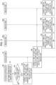
- time information indicating a timing at which a preset time correction process is to be performed is set(S1).
- the time correction timing information is configured such that the time can be set in units of minutes, and a time other than a time in which the ones place value of the minutes unit is "0" or "5" is set.
- the time correction processor 44 receives the clocked time of the controller built-in clock 41 as the standard time.
- the time correction processor 44 monitors whether the time of the controller built-in clock 41 coincides with the time correction timing set in the time correction timing setter 43, that is, whether the time correction timing has arrived (S2).
- the time correction processor 44 determines that the time correction timing has arrived ("YES" in S2), the time correction processor 44 transmits a time correction instruction for correcting the clocked time of the built-in clock to the standard time from the central-outdoor unit communicator 45 to the outdoor unit 10 (S3).
- the time correction instruction transmitted from the system controller 40 is received by the outdoor unit-central communicator 13 of the outdoor unit 10. Based on the received time correction instruction, the outdoor unit operation control unit 14 corrects the outdoor unit built-in clock 11 with the corresponding standard time. Further, the time correction instruction is transferred to the indoor units 20a to 20c connected to the outdoor unit-indoor unit communicator 12 from the outdoor unit-indoor unit communicator 12 (S4).
- the time correction instruction transferred from the outdoor unit 10 is received by the indoor unit-outdoor unit communicator 23 of each of the indoor units 20a to 20c. Then, based on the received time correction instruction, the indoor unit operation control unit 24 corrects the indoor unit built-in clock 21 with the corresponding standard time. Further, the time correction instruction is transmitted from the indoor unit-remote controller communicator 22 to each of the connected remote controllers 30a to 30c (S5, S6, and S7).
- the time correction instruction transmitted from each of the indoor units 20a to 20c is received by the remote controller-indoor unit communicator 31 of each of the remote controllers 30a to 30c. Then, based on the received time correction instruction, the time correction execution unit 35 corrects the remote controller built-in clock 33 with the corresponding standard time.
- the time deviation of the remote controller built-in clock 33 of the remote controller 30 is less than 1 minute by performing the process as described above.
- a correction is not made for times that span a time in which the ones place value of the minutes unit is "0" or "5".
- the timer setting relating to the operation of the indoor unit 20 the possibility that the time corresponds to a blank period or an overlapping period which occurs due to performing the time correction process is reduced.
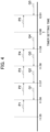
- the time correction timing is set to 11:56 and a time delay of less than 1 minute occurs in the remote controller built-in clock 33, for example.
- the clocked time is corrected as shown by arrow P1 by means of the time correction process.
- the time correction timing is set to 11:57 while a time delay of less than 1 minute occurs in the built-in clock.
- the clocked time is corrected as shown by arrow P2. If the time correction timing is set to 11:58, the clocked time is corrected as shown by arrow P3. If the time correction timing is set to 11:59, the clocked time is corrected as shown by arrow P4. If the time correction timing is set to 12:01, the clocked time is corrected as shown by arrow P5.
- the time correction timing is set to 11:56 and the remote controller built-in clock 33 advances by less than 1 minute.
- the clocked time is corrected by means of the time correction process as shown by arrow Q1.
- the time correction timing is set to 11:57 while the built-in clock advances by less than 1 minute.
- the clocked time is corrected as shown by arrow Q2. If the time correction timing is set to 11:58, the clocked time is corrected as shown by arrow Q3. If the time correction timing is set to 11:59, the clocked time is corrected as shown by arrow Q4. If the time correction timing is set to 12:01, the clocked time is corrected as shown by arrow Q5.
- the operation specified in the timer setting can be properly and surely performed.
- the configuration of an air conditioning system 1B using a central control device according to a second embodiment of the present invention is the same as the configuration of the air conditioning system 1A shown in FIG. 1 described in the first embodiment. Therefore, a detailed description of parts having the same functions will be omitted.
- the time specified in the timer setting operation of the indoor unit 20 can be set in units of minutes, and any one of "0" to "59” can be input as a value of the minutes unit.
- the time correction timing information can be set in units of seconds. Further, in the time correction timing setter 43, a time in which the value of the seconds unit is "30" is set as the time correction timing information.
- the time correction process is performed similarly to the process described in the first embodiment while the time correction timing information is set in this way.
- the time deviation of the remote controller built-in clock 33 of the remote controller 30 is less than 30 seconds, in the remote controller built-in clock 33, a correction is not made for times that span a time in which the value of the seconds unit is "0".
- the time correction timing is set to 11 :55:30 and the time delay of less than 30 seconds occurs in the remote controller built-in clock 33, for example.
- the clocked time is corrected as shown by arrow P11 by means of the time correction process.
- the time correction timing is set to 11:56:30 while a time delay of less than 30 seconds occurs in the built-in clock.
- the clocked time is corrected as shown by arrow P12. If the time correction timing is set to 11 :57:30, the clocked time is corrected as shown by arrow P13.
- the clocked time is corrected as shown by arrow P14. If the time correction timing is set to 11 :59:30, the clocked time is corrected as shown by arrow P15. If the time correction timing is set to 12:00:30, the clocked time is corrected as shown by arrow P16.
- the time correction timing is set to 11:55:30 and the remote controller built-in clock 33 advances by less than 30 seconds.
- the clocked time is corrected by means of the time correction process as shown by arrow Q11.
- the time correction timing is set to 11:56:30 while the built-in clock advances by less than 30 seconds.
- the clocked time is corrected as shown by arrow Q12. If the time correction timing is set to 11:57:30, the clocked time is corrected as shown by arrow Q13. If the time correction timing is set to 11 :58:30, the clocked time is corrected as shown by arrow Q14. If the time correction timing is set to 11:59:30, the clocked time is corrected as shown by arrow Q15. If the time correction timing is set to 12:00:30, the clocked time is corrected as shown by arrow Q16.
- the time correction As described above, even if the time is specified by using a minute numerical value such as the time of 11:58:00 in the timer setting, the corresponding operation can be properly and surely performed, for example.
- the configuration of an air conditioning system 1C using a central control device according to a third embodiment of the present invention is the same as the configuration of the air conditioning system 1A shown in FIG. 1 described in the first embodiment. Therefore, a detailed description of parts having the same functions is omitted.
- the time specified in the timer setting operation of the indoor unit 20 can be set in units of minutes, and that the ones place value of the minutes unit is often "0" or "5" as in the first embodiment.
- the time correction timing information can be set in units of seconds. Further, in the time correction timing setter 43, as the time correction timing information, a time is set in which the ones place value of the minutes unit is "2" or "7" and the value of the seconds unit is "30".
- the time correction process is performed similarly to the process described in the first embodiment while the time correction timing information is set in this way.
- the time deviation of the remote controller built-in clock 33 of the remote controller 30 is less than 2 minutes and 30 seconds, in the remote controller built-in clock 33, a correction is not made for times that span a time in which the ones place value of the minutes unit is "0" or "5".
- the time correction timing is set to 11:57:30 and the time delay of less than 2 minutes and 30 seconds occurs in the remote controller built-in clock 33, for example.
- the clocked time is corrected as shown by arrow P21 by means of the time correction process.
- time correction timing is set to 11:57:30 and the remote controller built-in clock 33 advances by less than 2 minutes and 30 seconds.
- the clocked time is corrected as shown by arrow Q21 by means of the time correction process.
- the corresponding operation can be properly and surely performed with high accuracy in the timer setting.
- the time correction process of the remote controller built-in clock 33 of each of the remote controllers 30 is performed by avoiding a time at which a timer relating to the operation of the indoor unit 20 is highly likely to be set. Accordingly, when the timer setting operation is performed in the remote controller 30, the possibility that the time specified in the timer setting corresponds to a blank period or an overlapping period which occurs due to performing the time correction process is reduced. Further, it is possible to avoid as much as possible a situation where an operation specified by the user is not appropriately performed.
- connection mode is not limited thereto.
- the system controller 40 may be directly connected to all of the outdoor units 10, the indoor units 20, and the remote controllers 30 individually, for example.
- all pieces of equipment namely the system controller 40, the remote controllers 30, the outdoor units 10, and the indoor units 20, may be communicatively connected to a single bus line. Further, each piece of equipment may be connected by means of wireless communication.
Landscapes
- Engineering & Computer Science (AREA)
- Human Computer Interaction (AREA)
- Chemical & Material Sciences (AREA)
- Combustion & Propulsion (AREA)
- Mechanical Engineering (AREA)
- General Engineering & Computer Science (AREA)
- Computer Networks & Wireless Communication (AREA)
- Physics & Mathematics (AREA)
- General Physics & Mathematics (AREA)
- Air Conditioning Control Device (AREA)
- Electric Clocks (AREA)
- Selective Calling Equipment (AREA)
Applications Claiming Priority (1)
| Application Number | Priority Date | Filing Date | Title |
|---|---|---|---|
| PCT/JP2020/013313 WO2021192087A1 (ja) | 2020-03-25 | 2020-03-25 | 空調システムの中央管理装置および時刻補正方法 |
Publications (2)
| Publication Number | Publication Date |
|---|---|
| EP4130596A1 true EP4130596A1 (de) | 2023-02-08 |
| EP4130596A4 EP4130596A4 (de) | 2023-07-05 |
Family
ID=77890015
Family Applications (1)
| Application Number | Title | Priority Date | Filing Date |
|---|---|---|---|
| EP20926417.5A Pending EP4130596A4 (de) | 2020-03-25 | 2020-03-25 | Zentrale verwaltungsvorrichtung für eine klimaanlage und zeitkorrekturverfahren |
Country Status (4)
| Country | Link |
|---|---|
| EP (1) | EP4130596A4 (de) |
| JP (1) | JP7425182B2 (de) |
| CN (1) | CN115315597B (de) |
| WO (1) | WO2021192087A1 (de) |
Family Cites Families (11)
| Publication number | Priority date | Publication date | Assignee | Title |
|---|---|---|---|---|
| JPH01265398A (ja) | 1988-04-18 | 1989-10-23 | Hitachi Ltd | ビル管理システム制御の方式 |
| JPH06185788A (ja) * | 1992-12-11 | 1994-07-08 | Noritz Corp | 空気調和機 |
| JP2005337614A (ja) * | 2004-05-28 | 2005-12-08 | Daikin Ind Ltd | スケジュール制御装置、空気調和装置、スケジュール制御システムおよびスケジュール制御方法 |
| JP2007046885A (ja) * | 2005-07-12 | 2007-02-22 | Matsushita Electric Ind Co Ltd | 空気調和機 |
| JP2009115380A (ja) * | 2007-11-06 | 2009-05-28 | Mitsubishi Electric Corp | 空気調和機 |
| CN101976038A (zh) * | 2010-09-14 | 2011-02-16 | 广东美的电器股份有限公司 | 一种时间自校准空调器及其时间自校准控制方法 |
| JP5260613B2 (ja) * | 2010-10-01 | 2013-08-14 | シャープ株式会社 | 空気調和機 |
| JP6040348B2 (ja) * | 2012-05-15 | 2016-12-07 | 株式会社ノーリツ | 給湯システム |
| CN104521243A (zh) * | 2012-08-08 | 2015-04-15 | 松下知识产权经营株式会社 | 家电设备、家电系统和服务器装置 |
| CN105159051B (zh) * | 2014-05-27 | 2018-05-25 | 大金工业株式会社 | 计时同步方法及应用其的空调系统 |
| JP2017078583A (ja) * | 2015-10-19 | 2017-04-27 | 株式会社ノーリツ | 通信装置 |
-
2020
- 2020-03-25 WO PCT/JP2020/013313 patent/WO2021192087A1/ja not_active Ceased
- 2020-03-25 CN CN202080098855.6A patent/CN115315597B/zh active Active
- 2020-03-25 EP EP20926417.5A patent/EP4130596A4/de active Pending
- 2020-03-25 JP JP2022509876A patent/JP7425182B2/ja active Active
Also Published As
| Publication number | Publication date |
|---|---|
| JPWO2021192087A1 (de) | 2021-09-30 |
| WO2021192087A1 (ja) | 2021-09-30 |
| EP4130596A4 (de) | 2023-07-05 |
| CN115315597A (zh) | 2022-11-08 |
| CN115315597B (zh) | 2025-04-22 |
| JP7425182B2 (ja) | 2024-01-30 |
Similar Documents
| Publication | Publication Date | Title |
|---|---|---|
| EP2884760B1 (de) | Elektrisches haushaltsgerät und elektrisches haushaltssystem | |
| EP2857771A1 (de) | Verwaltungssystem für eine kühlvorrichtung | |
| EP3041255B1 (de) | Elektrische vorrichtung, klimaanlage, externe steuerung, tragbares endgerät und klimaanlagensystem | |
| EP3176698B1 (de) | Vorrichtungsverwaltungseinrichtung, verwaltungsprogrammaktualisierungsverfahren und programm | |
| US9471053B2 (en) | Notification method, notification device, notification system, storage medium, information exchange networking service providing server, and mobile terminal | |
| EP3124885B1 (de) | System, zur regelung einer klimaanlage | |
| EP2853824B1 (de) | Klimatisierungssystem | |
| EP3112766B1 (de) | Steuerung einer wärmequellenausrüstung | |
| US11255564B2 (en) | Air-conditioner | |
| EP4130596A1 (de) | Zentrale verwaltungsvorrichtung für eine klimaanlage und zeitkorrekturverfahren | |
| WO2015182505A1 (ja) | 計時同期方法及びそれを応用したエアコンシステム | |
| JP7288598B2 (ja) | 空気調和機 | |
| JP2001186658A (ja) | デマンド制御装置 | |
| JP2023078562A (ja) | 空調システム管理装置および空調システム管理方法 | |
| JP2010114835A (ja) | 設備機器の通信制御装置、管理システム及び通信制御方法 | |
| WO2017216956A1 (ja) | 空気調和システム | |
| JP7739996B2 (ja) | 空気調和システム | |
| WO2023148866A1 (ja) | ヒートポンプシステムおよび制御システム | |
| JP4446896B2 (ja) | 空気調和システム及び空気調和機 | |
| JP6961091B2 (ja) | プログラム転送システム及びプログラム転送方法 | |
| JPH0654371A (ja) | 空気調和機用ワイヤレスリモコン装置 | |
| JP7722161B2 (ja) | 空気調和システム | |
| JP2026042910A (ja) | 制御システム | |
| JP2021050832A (ja) | 空気調和機 | |
| JPS6011040A (ja) | 空調設備のスケジユ−ル起動停止装置 |
Legal Events
| Date | Code | Title | Description |
|---|---|---|---|
| STAA | Information on the status of an ep patent application or granted ep patent |
Free format text: STATUS: THE INTERNATIONAL PUBLICATION HAS BEEN MADE |
|
| PUAI | Public reference made under article 153(3) epc to a published international application that has entered the european phase |
Free format text: ORIGINAL CODE: 0009012 |
|
| STAA | Information on the status of an ep patent application or granted ep patent |
Free format text: STATUS: REQUEST FOR EXAMINATION WAS MADE |
|
| 17P | Request for examination filed |
Effective date: 20221021 |
|
| AK | Designated contracting states |
Kind code of ref document: A1 Designated state(s): AL AT BE BG CH CY CZ DE DK EE ES FI FR GB GR HR HU IE IS IT LI LT LU LV MC MK MT NL NO PL PT RO RS SE SI SK SM TR |
|
| DAV | Request for validation of the european patent (deleted) | ||
| DAX | Request for extension of the european patent (deleted) | ||
| A4 | Supplementary search report drawn up and despatched |
Effective date: 20230602 |
|
| RIC1 | Information provided on ipc code assigned before grant |
Ipc: H04Q 9/00 20060101ALI20230526BHEP Ipc: F24F 11/61 20180101AFI20230526BHEP |
|
| STAA | Information on the status of an ep patent application or granted ep patent |
Free format text: STATUS: EXAMINATION IS IN PROGRESS |
|
| 17Q | First examination report despatched |
Effective date: 20250912 |