EP4130592B1 - Luftreinigungsvorrichtung - Google Patents
Luftreinigungsvorrichtung Download PDFInfo
- Publication number
- EP4130592B1 EP4130592B1 EP21792037.0A EP21792037A EP4130592B1 EP 4130592 B1 EP4130592 B1 EP 4130592B1 EP 21792037 A EP21792037 A EP 21792037A EP 4130592 B1 EP4130592 B1 EP 4130592B1
- Authority
- EP
- European Patent Office
- Prior art keywords
- air purification
- temperature
- purification apparatus
- unit
- filter
- Prior art date
- Legal status (The legal status is an assumption and is not a legal conclusion. Google has not performed a legal analysis and makes no representation as to the accuracy of the status listed.)
- Active
Links
Images


Classifications
-
- B—PERFORMING OPERATIONS; TRANSPORTING
- B01—PHYSICAL OR CHEMICAL PROCESSES OR APPARATUS IN GENERAL
- B01D—SEPARATION
- B01D46/00—Filters or filtering processes specially modified for separating dispersed particles from gases or vapours
- B01D46/66—Regeneration of the filtering material or filter elements inside the filter
- B01D46/80—Chemical processes for the removal of the retained particles, e.g. by burning
- B01D46/82—Chemical processes for the removal of the retained particles, e.g. by burning with catalysts
-
- B—PERFORMING OPERATIONS; TRANSPORTING
- B01—PHYSICAL OR CHEMICAL PROCESSES OR APPARATUS IN GENERAL
- B01D—SEPARATION
- B01D46/00—Filters or filtering processes specially modified for separating dispersed particles from gases or vapours
- B01D46/42—Auxiliary equipment or operation thereof
- B01D46/429—Means for wireless communication
-
- B—PERFORMING OPERATIONS; TRANSPORTING
- B01—PHYSICAL OR CHEMICAL PROCESSES OR APPARATUS IN GENERAL
- B01D—SEPARATION
- B01D46/00—Filters or filtering processes specially modified for separating dispersed particles from gases or vapours
- B01D46/42—Auxiliary equipment or operation thereof
- B01D46/44—Auxiliary equipment or operation thereof controlling filtration
- B01D46/448—Auxiliary equipment or operation thereof controlling filtration by temperature measuring
-
- B—PERFORMING OPERATIONS; TRANSPORTING
- B01—PHYSICAL OR CHEMICAL PROCESSES OR APPARATUS IN GENERAL
- B01D—SEPARATION
- B01D46/00—Filters or filtering processes specially modified for separating dispersed particles from gases or vapours
- B01D46/42—Auxiliary equipment or operation thereof
- B01D46/44—Auxiliary equipment or operation thereof controlling filtration
- B01D46/46—Auxiliary equipment or operation thereof controlling filtration automatic
-
- B—PERFORMING OPERATIONS; TRANSPORTING
- B01—PHYSICAL OR CHEMICAL PROCESSES OR APPARATUS IN GENERAL
- B01D—SEPARATION
- B01D46/00—Filters or filtering processes specially modified for separating dispersed particles from gases or vapours
- B01D46/66—Regeneration of the filtering material or filter elements inside the filter
- B01D46/70—Regeneration of the filtering material or filter elements inside the filter by acting counter-currently on the filtering surface, e.g. by flushing on the non-cake side of the filter
-
- B—PERFORMING OPERATIONS; TRANSPORTING
- B01—PHYSICAL OR CHEMICAL PROCESSES OR APPARATUS IN GENERAL
- B01D—SEPARATION
- B01D2273/00—Operation of filters specially adapted for separating dispersed particles from gases or vapours
- B01D2273/30—Means for generating a circulation of a fluid in a filtration system, e.g. using a pump or a fan
-
- B—PERFORMING OPERATIONS; TRANSPORTING
- B01—PHYSICAL OR CHEMICAL PROCESSES OR APPARATUS IN GENERAL
- B01D—SEPARATION
- B01D2279/00—Filters adapted for separating dispersed particles from gases or vapours specially modified for specific uses
- B01D2279/40—Filters adapted for separating dispersed particles from gases or vapours specially modified for specific uses for cleaning of environmental air, e.g. by filters installed on vehicles or on streets
-
- F—MECHANICAL ENGINEERING; LIGHTING; HEATING; WEAPONS; BLASTING
- F24—HEATING; RANGES; VENTILATING
- F24F—AIR-CONDITIONING; AIR-HUMIDIFICATION; VENTILATION; USE OF AIR CURRENTS FOR SCREENING
- F24F13/00—Details common to, or for air-conditioning, air-humidification, ventilation or use of air currents for screening
- F24F13/28—Arrangement or mounting of filters
-
- F—MECHANICAL ENGINEERING; LIGHTING; HEATING; WEAPONS; BLASTING
- F24—HEATING; RANGES; VENTILATING
- F24F—AIR-CONDITIONING; AIR-HUMIDIFICATION; VENTILATION; USE OF AIR CURRENTS FOR SCREENING
- F24F8/00—Treatment, e.g. purification, of air supplied to human living or working spaces otherwise than by heating, cooling, humidifying or drying
- F24F8/10—Treatment, e.g. purification, of air supplied to human living or working spaces otherwise than by heating, cooling, humidifying or drying by separation, e.g. by filtering
-
- F—MECHANICAL ENGINEERING; LIGHTING; HEATING; WEAPONS; BLASTING
- F24—HEATING; RANGES; VENTILATING
- F24F—AIR-CONDITIONING; AIR-HUMIDIFICATION; VENTILATION; USE OF AIR CURRENTS FOR SCREENING
- F24F8/00—Treatment, e.g. purification, of air supplied to human living or working spaces otherwise than by heating, cooling, humidifying or drying
- F24F8/90—Cleaning of purification apparatus
Definitions
- the present invention relates to an air purification apparatus configured to purify air containing contaminants, and more specifically, to an air purification apparatus which may perform a cleaning operation of removing contaminants collected in a filter in a process of purifying air containing the contaminants.
- PM particulate matter
- ESP electrostatic precipitator
- the conventional air purification apparatus has the following problem.
- a physical collection operation is primarily essential, and when air is filtered, a large number of contaminants may be collected in a filter (or a configuration which may collect contaminants) in the air purification apparatus.
- the filtering process is performed, there occurs a problem in that the air purification performance of the filter in the air purification apparatus is rapidly decreased by the large number of collected contaminants, and as a result, sufficient air purification for the polluted air may not be performed.
- the conventional air purification apparatus requires a process of periodically replacing and cleaning the configuration of collecting contaminants, there occur problems in that inconvenience is given to users and a lot of maintenance costs are required.
- Document KR 2020 0 021 236 A discloses an air purifying apparatus capable of immediately discharging indoor air to outdoor space.
- the apparatus comprises a main passage unit, a bypass passage unit, dampers, a filter, a heater, and a blower.
- the main passage unit allows air to flow from a main inlet to a main outlet.
- the bypass passage unit is divided from the main passage unit and allows air to flow from the indoor space through a bypass inlet to the outdoor space through a bypass outlet.
- One damper for opening and closing a main inlet or a main outlet and another damper for bypassing opens and closes the bypass passage unit.
- the filter is arranged in the main passage unit, and the heater heats the filter.
- Both ends of a circulation pipe are each arranged on the main inlet and the main outlet side to communicate with the main passage unit.
- the blower is installed in the circulation pipe to transport air in the circulation pipe into the main passage unit.
- the apparatus further comprises a controller controls the damper for bypassing to open the bypass passage unit when the main passage unit is closed by malfunction of the damper for a main inlet or the damper for a main outlet.
- Document JP H05 332 124 A discloses a filter regeneration apparatus for internal combustion engine.
- the filter regeneration apparatus comprises a filter to collect particulates contained in exhaust gas, a microwave generating means to heat the collected particulates and a thermal resistance air blowing means to circulate air to burn the heated particulates through the filter.
- Document KR 100 861 778 B discloses an auto cleaning air-filter unit for an air conditioner.
- the filter unit includes pressure detection sensors, a control unit, and blowers.
- the detection sensors are installed to detect pressure of air, which is introduced or discharged with respect to a filter of a filter chamber through an inlet duct and an outlet duct, respectively.
- the filter and the pressure detection sensors are installed on the control unit.
- the filter is equipped with blowers that are connected to the control unit to generate air current.
- the filter unit further comprises a heater provided at a side of the blower to supply hot air, and a humidity sensor installed in the output duct having a division unit connected to an outdoor discharge pipe and an indoor discharge pipe.
- Document US 2011 / 067 571 A discloses an air purification apparatus comprising a duct, a filter for air purification, an electrostatically atomizing device, a fan, and a switching device.
- the duct has an inlet and an outlet.
- the filter is placed inside of the duct.
- the electrostatically atomizing device is configured to generate a mist of charged minute water particles by means of electrostatically atomizing phenomenon and discharge the same into the duct.
- the fan is configured to send air from the inlet to the outlet.
- the switching device is configured to switch one of a first mode and a second mode.
- the air purification apparatus is configured to send a mist of charged minute water particles from the electrostatically atomizing device to the outlet not through the filter in said first mode.
- the air purification apparatus is configured to send a mist of charged minute water particles from the electrostatically atomizing device (30) to the filter (20) in the second mode.
- Document US 2013 / 125 753 A discloses an apparatus for cleaning a filter for removing particulate matter comprising a filter installed in a exhaust passage of an internal combustion engine and capturing the particulate matter included in the exhaust gas; an injector being able to inject high-pressure air and high-pressure vapor to the filter in a opposite direction to a flow direction of the exhaust gas; a high-pressure air feeder being able to feed the high-pressure air to the injector; and a high-pressure vapor feeder being able to feed the high-pressure vapor to the injector.
- the present invention is directed to providing an air purification apparatus which may perform a cleaning operation for a filter in which contaminants are collected.
- the present invention is also directed to providing an air purification apparatus with improved cleaning efficiency for a filter in which contaminants are collected.
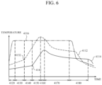
- an air purification apparatus for purifying and discharging purified air including a first flow path which is a movement path of air, a second flow path which is a movement path of the air, and a main pipe including a first filter positioned between the first flow path and the second flow path and configured to collect at least some of contaminants contained in the air, a first main area positioned between the first flow path and the first filter, and a second main area positioned between the second flow path and the first filter, wherein the air purification apparatus may operate in a filtering mode in which at least some of the contaminants contained in the air introduced into the main pipe are collected in the first filter or a cleaning mode in which at least some of the contaminants collected in the first filter in the filtering mode are removed, an operation section of the air purification apparatus in the cleaning mode includes a first section and a second section, the first section and the second section are divided based on a first division time point, and a temperature change
- an air purification apparatus which can selectively perform a purification operation for introduced air and a cleaning operation for a filter configuration.
- an air purification apparatus for purifying and discharging polluted air including a first flow path which is a movement path of air, a second flow path which is a movement path of the air, and a main pipe including a first filter which is positioned between the first flow path and the second flow path and which may collect at least some of contaminants contained in the air, a first main area positioned between the first flow path and the first filter, and a second main area positioned between the second flow path and the first filter, wherein the air purification apparatus operates in a filtering mode in which at least some of the contaminants contained in the air introduced into the main pipe are collected in the first filter or a cleaning mode in which at least some of the contaminants collected in the first filter in the filtering mode are removed, an operation section of the air purification apparatus in the cleaning mode includes a first section and a second section, the first section and the second section are divided with respect to a first division time point, and a temperature change rate in the first main area is changed before and after the first division time point
- the first section may have a first instantaneous temperature increase rate at an entry time point of the first division time point
- the second section may have a second instantaneous temperature increase rate at an end time point of the first division time point
- the first instantaneous temperature increase rate may be smaller than the second instantaneous temperature increase rate
- the first section may include a first division adjacent section
- the second section may include a second division adjacent section
- the first division adjacent section and the second division adjacent section may have the same time range
- an average temperature increase rate of the first main area in the first division adjacent section may be smaller than an average temperature increase rate of the first main area in the second division adjacent section.
- the first filter is coated with a first catalyst which may mediate a reaction to the contaminants, and the first division time point is after a time point when the reaction based on the first catalyst starts.
- the second main area When the air purification apparatus operates in the cleaning mode, with respect to the air flow within the main pipe, the second main area may be positioned upstream of the first filter, and the first main area may be positioned downstream of the first filter.
- the air introduced from the first flow path may be discharged through the second flow path, and at least some of the contaminants contained in the introduced air may be collected in the first filter as they move from the first main area to the second main area.
- the air purification apparatus includes a control unit configured to control the air purification apparatus to operate in the filtering mode or the cleaning mode, wherein the control unit determines that the cleaning of the air purification apparatus has been started when the operation section in the cleaning mode of the air purification apparatus includes the first division time point.
- the air purification apparatus includes a control unit configured to control the air purification apparatus to operate in the filtering mode or the cleaning mode, wherein the control unit determines that the cleaning of the air purification apparatus has been started when a temperature of the second main area is higher than or equal to a predetermined cleaning start temperature.
- the first filter may include a first filter area and a second filter area, the first filter area may be closer to the first main area than the second filter area, the second filter area may be closer to the second main area than the first filter area, and a temperature of the first filter area may increase as a heating reaction occurs in the second filter area.
- the control unit may determine that the cleaning of the air purification apparatus has been completed when a second time elapses with respect to the time point when it is determined that the cleaning of the air purification apparatus has been started, and the heating of a heating unit may be ended when it is determined that the cleaning of the air purification apparatus has been completed.
- the control unit may determine that the cleaning of the air purification apparatus has been completed when a first time elapses with respect to a time point when the heat-generation of the heating unit starts.
- control unit may determine that the cleaning of the air purification apparatus has been completed when the temperature of the second main area is lower than or equal to a predetermined cleaning completion temperature.
- the control unit may determine that the cleaning of the air purification apparatus has been started as a temperature of the first main area is higher than the temperature of the second main area and determine that the cleaning of the air purification apparatus has been completed as the temperature of the first main area is lower than the temperature of the second main area.
- the air purification apparatus includes a heating unit which may emit heat so that the air within the air purification apparatus is heated, wherein the first filter is coated with a first catalyst, the heating unit emits heat so that the temperature of the second main area is included in a predetermined temperature range -the predetermined temperature range at least includes an activation temperature of the first catalyst- when the air purification apparatus is operating in the cleaning mode.
- control unit may control a heating intensity of the heating unit to decrease.
- the air purification apparatus may further include a first opening and closing member positioned between the first flow path and the first main area and a second opening and closing member positioned between the second flow path and the second main area, wherein the first opening and closing member may allow communication or closing between the first flow path and the first main area, the second opening and closing member may allow communication or closing between the second flow path and the second main area, and when a temperature in at least a partial area within the main housing is lower than or equal to a predetermined cooling temperature, the first opening and closing member may allow the first flow path and the first main area to communication with each other, and the second opening and closing member may allow the second flow path and the second main area to communicate with each other.
- the air purification apparatus may further include a first opening and closing member positioned between the first flow path and the first main area and a second opening and closing member positioned between the second flow path and the second main area, wherein the first opening and closing member may allow communication or closing between the first flow path and the first main area, the second opening and closing member may allow communication or closing between the second flow path and the second main area, and when the air purification apparatus operates in the cleaning mode, the first opening and closing member may allow at least a part between the first flow path and the first main area to be closed, and the second opening and closing member may allow at least a part between the second flow path and the second main area to be closed.
- the air purification apparatus may further include a sub-pipe configured to communicate the second main area and the first main area, wherein the sub-pipe may include a second filter coated with a second catalyst, a first auxiliary area positioned between the second main area and the second filter, and a second auxiliary area positioned between the first main area and the second filter, a temperature of at least a part of the second auxiliary area may be lower than a temperature of at least a part of the first auxiliary area when a temperature of the second catalyst is lower than an activation temperature of the second catalyst, and the temperature of at least a part of the second auxiliary area may be higher than the temperature of at least a part of the first auxiliary area when the temperature of the second catalyst is higher than the activation temperature of the second catalyst.
- the sub-pipe may include a second filter coated with a second catalyst, a first auxiliary area positioned between the second main area and the second filter, and a second auxiliary area positioned between the first main area and the second filter, a temperature of at least a part of
- the reaction based on the first catalyst may be a heating reaction.
- the present invention relates to an air purification apparatus for purifying air containing contaminants, and more specifically, to an air purification apparatus which may perform a cleaning operation of removing particles collected in a filter in a process of purifying air containing contaminants.
- An air purification apparatus refers to an apparatus for removing at least some of contaminants contained in air.
- the contaminants contained in the air may be classified into particulate matter on the several micrometer scale and nano-scaled gaseous matter on the several Angstrom scale to nano scale according to their sizes.
- particulate contaminants are generally known as particulate matter (PM).
- the air purification performed by the air purification apparatus is not limited to the specific types of contaminants described above.
- contaminants to be described below are not limited to either particulate matter or gaseous matter, and are construed as a generic term for matters which may be collected by a filter included in the air purification apparatus.
- polluted air to be described below is construed to refer to air containing the contaminants.
- the air purification as defined in the present invention may mean that contaminants are separated or removed from polluted air provided inside a housing of the air purification apparatus.
- the air purification may mean that the contaminants are physically removed from the polluted air (e.g., polluted particles having a diameter greater than a filter transmission diameter smaller than diameters of the polluted particles are caught by the filter or collected by the filter due to electrical attraction to a surface of the filter) or chemically removed (e.g., in the process of passing through the filter, the polluted particles are removed by the chemical reaction, combustion, and the like caused by a sufficient high internal temperature).
- FIGS. 1 to 23 an air management system and an air purification apparatus according to a first embodiment of the present invention will be described with reference to FIGS. 1 to 23 .
- FIG. 1 is a configuration diagram showing an air management system according to a first embodiment of the present invention.
- an air management system 1 may include a main server 1000, an air purification apparatus 2000, and a user terminal 3000.
- the main server 1000 may be connected to the air purification apparatus 2000 and the user terminal 3000.
- the main server 1000 may control the air purification apparatus 2000.
- the main server 1000 may generate data which may control the air purification apparatus 2000.
- the main server 1000 may transmit data which may control the air purification apparatus 2000 and receive data related to a state of the air purification apparatus 2000.
- the main server 1000 may update and store information related to the state of the air purification apparatus 2000.
- the main server 1000 may exchange data with the user terminal 3000.
- the main server 1000 may generate the data which may control the air purification apparatus 2000 based on an input provided from the user terminal 3000.
- the main server 1000 may transmit the data related to the state of the air purification apparatus 2000 to the user terminal 3000.
- the main server may refer to software, program, hardware device or a combination thereof equipped with a computing system which may perform networking such as a web server, a cloud server, and a computing server.
- the main server 1000 may include an integrated control unit 1200, a storage unit 1400, and a main communication unit 1600.
- the integrated control unit 1200 may control a configuration included in the main server 1000.
- the integrated control unit 1200 may control the storage unit 1400 and the main communication unit 1600.
- the integrated control unit 1200 may be implemented as a CPU or a similar device according to hardware, software, or a combination thereof.
- the integrated control unit 1200 may be provided in the form of an electronic circuit configured to perform a control function by processing an electrical signal.
- the integrated control unit 1200 may be provided in the form of a program, application, firmware, or the like processed by the integrated control unit 1200 which is hardware.
- the storage unit 1400 may store data provided from the air purification apparatus 2000 and data provided from the user terminal 3000.
- State information on the air purification apparatus 2000 may be stored in the storage unit 1400.
- the data provided from the air purification apparatus 2000 may include temperature data, pressure data, particulate matter measurement data, power consumption data, data on whether a filter is abnormal, data on an operating time of the filter, and data on whether an emergency situation occurs of each air purification apparatus.
- the data for controlling the air purification apparatus 2000 may be stored in the storage unit 1400.
- cleaning start information and cleaning end information on the air purification apparatus 2000 may be stored in the storage unit 1400.
- the storage unit 1400 may refer to a hard disk drive (HDD), a memory card, an optical disc, a flash memory, or other storage devices.
- HDD hard disk drive
- memory card a memory card
- optical disc a hard disk drive
- flash memory a flash memory
- the main communication unit 1600 may communicate with the air purification apparatus 2000 and the user terminal 3000.
- the main communication unit 1600 may communicate with the air purification apparatus 2000 and the user terminal 3000 wirelessly or by wire.
- the main communication unit 1600 may transmit the changed state information on the air purification apparatus 2000 to the user terminal 3000.
- whether the state information on the air purification apparatus 2000 is changed may be determined by the integrated control unit 1200.
- the main communication unit 1600 may transmit a signal for controlling the operation of the air purification apparatus 2000 to the air purification apparatus 2000.
- the signal for controlling the operation may be based on the data provided from the user terminal 3000 or may be acquired by the integrated control unit 1200.
- the main communication unit 1600 may refer to a configuration which may perform a data communication function, such as a local area network (LAN), Wi-Fi, Bluetooth, a long-term evolution (LTE) communication network, or a fifth generation (5G) communication network.
- a data communication function such as a local area network (LAN), Wi-Fi, Bluetooth, a long-term evolution (LTE) communication network, or a fifth generation (5G) communication network.
- LAN local area network
- Wi-Fi Wireless Fidelity
- Bluetooth Bluetooth
- LTE long-term evolution
- 5G fifth generation
- the air purification apparatus 2000 may purify air.
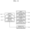
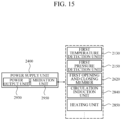
- the air purification apparatus 2000 includes a control unit 2200, a power supply unit 2400, and a communication unit 2600.
- the control unit 2200 may control individual components of the air purification apparatus 2000 based on the control data received from the main server 1000.
- control unit 2200 may control the individual components of the air purification apparatus 2000 according to a predetermined standard.
- control unit 2200 may control the individual components of the air purification apparatus 2000 based on an input provided by a user.
- the control unit 2200 may be implemented as a CPU or a similar device according to hardware, software, or a combination thereof.
- the control unit 2200 may be provided in the form of an electronic circuit configured to perform a control function by processing an electrical signal.
- the control unit 2200 may be provided in the form of a program, application, firmware, or the like processed by the control unit 2200 which is hardware.
- An electrical signal for performing an operation of a component of the air purification apparatus 2000 to be performed below may be construed as being acquired by the control unit 2200 unless otherwise specified.
- information on the input provided by a manager or a user of the air purification apparatus 2000 may be construed as being provided to the control unit 2200 unless otherwise specified.
- the power supply unit 2400 may apply power to the individual components of the air purification apparatus 2000.
- the power supply unit 2400 may cut off the power provided to the individual components or adjust the amount of power supplied.
- the power supply unit 2400 may cut off the power applied to the individual components or control the amount of power supplied based on a control signal provided from the control unit 2200.
- the power supply unit 2400 may cut off power applied to a specific component of the air purification apparatus 2000.
- the communication unit 2600 may communicate with the main server 1000.
- the communication unit 2600 may transmit data on the air purification apparatus 2000 to the main communication unit 1600. According to one example, the communication unit 2600 may provide state information on the air purification apparatus 2000. The communication unit 2600 may output visual information or auditory information related to the state information.
- the communication unit may receive an operation signal for the air purification apparatus 2000 from the main communication unit 1600.
- the communication unit 2600 may be implemented as various methods such as a local area network (LAN), Wi-Fi, Bluetooth, a long-term evolution (LTE) communication network, and a fifth generation (5G) communication network.
- LAN local area network
- Wi-Fi Wireless Fidelity
- Bluetooth Wireless Fidelity
- LTE long-term evolution
- 5G fifth generation
- the user terminal 3000 may transmit or receive data on the air purification apparatus 2000 with the main server 1000.
- the user terminal 3000 may acquire the state information on the air purification apparatus 2000 from the main communication unit 1600.
- the user terminal 3000 may receive an input related to the control of the air purification apparatus 2000 from the user so that the main server 1000 may output the control signal for the air purification apparatus 2000.
- the user terminal 3000 may be any electronic device equipped with a wireless communication function, such as smart phones, notebook computers, tablet PCs, desktop computers, and portable media players.
- the user terminal 3000 may directly control the air purification apparatus 2000.
- the user terminal 3000 may exchange data with the air purification apparatus 2000 through the communication unit 2600 of the air purification apparatus 2000.
- Data on the state change of the air purification apparatus 2000 may also be directly transmitted to the user terminal 3000, and data on the state change of the air purification apparatus 2000 may be transmitted to and managed by the main server 1000.
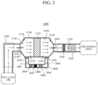
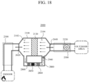
- FIG. 2 is a schematic diagram showing the air purification apparatus according to the first embodiment of the present invention.
- the air purification apparatus 2000 may include an inlet 2300, an outlet 2500, a main housing 2100, and a sub-housing 2800.
- the main housing 2100 may be positioned between the inlet 2300 and the outlet 2500.
- the sub-housing 2800 may communicate with at least a part of the main housing 2100.
- the sub-housing 2800 may be fluidically connected by communicating with two points of the main housing 2100.
- a housing as defined in the present invention may be referred to as a pipe or a tube.
- Air provided through the inlet 2300 may flow inside the sub-housing 2800 through a point communicating with the main housing 2100.
- polluted air may be purified.
- the main housing 2100 may represent an external appearance of an air purification structure.
- the main housing 2100 may have an inclined surface in an area adjacent to the inlet 2300.
- the main housing 2100 may have an inclined surface in an area adjacent to the outlet 2500.
- a cross section of the main housing 2100 in a predetermined direction may have a predetermined shape.
- the predetermined shape may be a rectangle or a circle.
- the inclined surface of the adjacent area may include a first point and a second point closer to the inlet 2300 than the first point.
- the cross section in the predetermined direction at the first point may have a first area, and the cross section in the predetermined direction at the second point may have a second area. In this case, the first area may be greater than the second area.
- the main housing 2100 includes a first filter unit 2120, a first temperature detection unit 2130, a second temperature detection unit 2140, a first pressure detection unit 2150, a second pressure detection unit 2160, and an emergency temperature detection unit 2190.
- the first filter unit 2120 is positioned in the main housing 2100 to collect contaminants contained in the air.
- the first filter unit 2120 may be positioned between a first opening and closing member 2620 and a second opening and closing member 2640.
- a flow path through which at least air passes is provided in the first filter unit 2120.
- the first filter unit 2120 refers to a configuration including a filter which collects contaminants regardless of specific physical or chemical characteristics such as material, size, shape, and heat resistance temperature.
- the first filter unit 2120 is not limited to a specific material or a specific substance.
- the first filter unit 2120 may be at least one of a ceramic filter and a metal filter.
- the first filter unit 2120 may include a filter having a porous structure.
- the first filter unit 2120 may have a filter structure of a ceramic honeycomb structure.
- the first filter unit 2120 may include a first ceramic flow path and a second ceramic flow path.
- the first ceramic flow path may have an air flow path in a first filter direction from the inlet 2300 toward the outlet 2500 and an end surface on one surface of the first filter unit 2120 adjacent to the inlet 2300
- the second ceramic flow path may have an air flow path along a second filter direction opposite to the first filter direction and an end surface on the other surface of the first filter unit 2120 adjacent to the outlet 2500.
- the air provided to the first filter unit 2120 may be moved along the first ceramic flow path, and at least a part of the provided air may be moved along the second ceramic flow path.
- the first filter unit 2120 may include a plurality of first ceramic flow paths and a plurality of second ceramic flow paths. The plurality of first ceramic flow paths and the plurality of second ceramic flow paths may be alternately disposed to collect the contaminants in the air passing through the first filter unit 2120.
- the contaminants collected in the first filter unit 2120 need to be removed.
- the first filter unit 2120 may be cleaned by allowing a reaction to the accumulated contaminants to occur.
- the first filter unit 2120 is provided with a first catalyst for mediating a first reaction.
- the temperature of the first filter unit 2120 is higher than or equal to a predetermined temperature, a reaction based on the first catalyst may occur in the contaminants collected in the first filter unit 2120.
- the first reaction may be a heating reaction.
- the first filter unit 2120 may function as a heat source.
- the first temperature detection unit 2130 may be positioned between the first opening and closing member 2620 and the first filter unit 2120.
- the first temperature detection unit 2130 may be arranged on a partial surface of the main housing 2100.
- an area where the first temperature detection unit 2130 may be installed may be provided in the main housing 2100 in advance.
- the first temperature detection unit 2130 may be installed from the outside.
- the first main area 2102 may refer to an area between the first opening and closing member 2620 and the first filter unit 2120.
- the first temperature detection unit 2130 is connected to the control unit 2200.
- the first temperature detection unit 2130 acquires information on the temperature of at least a partial area of the first main area 2102. In addition, the first temperature detection unit 2130 may transmit the acquired information on the temperature of the first main area 2102 to the control unit 2200.
- the second temperature detection unit 2140 may be positioned between the second opening and closing member 2640 and the first filter unit 2120.
- the second temperature detection unit 2140 may be arranged on a partial surface of the main housing 2100.
- an area where the second temperature detection unit 2140 may be installed may be provided in the main housing 2100 in advance.
- the second temperature detection unit 2140 may be installed from the outside.
- the second main area 2104 may refer to an area between the second opening and closing member and the first filter unit.
- the second temperature detection unit 2140 may be connected to the control unit 2200.
- the second temperature detection unit 2140 may acquire information on the temperature of the at least a partial area of the second main area 2104. In addition, the second temperature detection unit 2140 may transmit the acquired information on the temperature of the second main area 2104 to the control unit 2200.
- the emergency temperature detection unit 2190 may be positioned in the main housing 2100.
- the emergency temperature detection unit 2190 may be positioned in the first main area 2102.
- the emergency temperature detection unit 2190 may be arranged in a downstream area with respect to the first filter unit 2120 when a circulation air flow is generated between the main housing 2100 and the sub-housing 2800.
- the emergency temperature detection unit 2190 may be positioned on the inclined surface of the main housing 2100 adjacent to the inlet 2300.
- the emergency temperature detection unit 2190 may be positioned in the sub-housing 2800.
- the emergency temperature detection unit 2190 may be positioned in a downstream area with respect to a second filter unit 2860 when a circulation air flow is generated between the main housing 2100 and the sub-housing 2800.
- the emergency temperature detection unit 2190 may be positioned in a downstream area with respect to a heating unit 2850.
- the emergency temperature detection unit 2190 may be connected to the control unit 2200.
- the emergency temperature detection unit 2190 may provide information on a temperature at a position of the emergency temperature detection unit 2190 to the control unit 2200.
- the control unit 2200 may acquire information on the operation of the air purification apparatus 2000 based on the temperature information provided from at least any one of the first temperature detection unit 2130, the second temperature detection unit 2140, and the emergency temperature detection unit 2190.
- the first temperature detection unit 2130, the second temperature detection unit 2140, and the emergency temperature detection unit 2190 are not essential configurations, and at least any one of the first temperature detection unit 2130, the second temperature detection unit 2140, and the emergency temperature detection unit 2190 may be removed.
- the first pressure detection unit 2150 may be positioned in the first main area 2102.
- the first pressure detection unit 2150 may be positioned on a non-inclined surface of the main housing 2100.
- a cross-sectional area in a predetermined vertical direction at a third point of the main housing 2100, wherein the third point is defined by a position where the first pressure detection unit 2150 is disposed may have a third area.
- a cross-sectional area in the predetermined vertical direction at a fourth point of the main housing 2100, wherein the fourth point may refer to any partial point in the area of the main housing 2100 in which the first filter unit 2120 is positioned, may have a fourth area.
- the third area and the fourth area may be the same.
- the first pressure detection unit 2150 is positioned at a position corresponding to the third point, so that it is possible to prevent the rotation of air turbulence which may occur when air flows in an area before and after the first filter unit 2120.
- the main housing 2100 may include a first coupling unit to which the first pressure detection unit 2150 may be coupled.
- the first coupling unit may be positioned at least any position of the main housing 2100 corresponding to the first main area 2102.
- the first pressure detection unit 2150 may acquire information on the pressure of at least a part of the first main area 2102.
- the first pressure detection unit 2150 may be connected to the control unit 2200. In this case, the first pressure detection unit 2150 may transmit information on the pressure of at least a partial area of the first main area 2102 to the control unit 2200 in real time or as necessary.
- the second pressure detection unit 2160 may be positioned on the non-inclined surface of the main housing 2100.
- a cross-sectional area in the predetermined vertical direction at a fifth point -the fifth point is defined by a position at which the second pressure detection unit 2160 is arranged- of the main housing 2100 may have a fifth area.
- the fifth area and the fourth area may be the same.
- the second pressure detection unit 2160 is positioned at a position corresponding to the fifth point, so that it is possible to prevent the rotation of air turbulence which may occur when air flows in the area before and after the first filter unit 2120.
- the main housing 2100 may include a second coupling unit to which the second pressure detection unit 2160 may be coupled.
- the second coupling unit may be positioned at least any position of the main housing 2100 corresponding to the second main area 2104.
- the second pressure detection unit 2160 may acquire information on the pressure of at least a part of the second main area 2104.
- the second pressure detection unit 2160 may be connected to the control unit 2200. In this case, the second pressure detection unit 2160 may transmit the information on the pressure of at least a partial area of the second main area 2104 to the control unit 2200 in real time or as necessary.
- the control unit 2200 may acquire filter abnormality information on the air purification apparatus 2000 based on the pressure information provided from the first pressure detection unit 2150 and the pressure information provided from the second pressure detection unit 2160.
- the air flowing through the inlet 2300 may be relatively polluted air.
- the inlet 2300 may be fluidically connected to an indoor or outdoor area to which the polluted air is provided.
- the air flowing through the inlet 2300 may be relatively polluted air compared to the air flowing through the outlet 2500.
- the air flowing through the outlet 2500 may be relatively purified air.
- the outlet 2500 may be fluidically connected to a discharge area through which the purified air is discharged.
- the air flowing through the outlet 2500 may be relatively purified air compared to the air flowing through the inlet 2300.
- the outlet 2500 may include an exhaust unit 2520 and an adsorption unit 2540.
- the exhaust unit 2520 may discharge the purified air to a discharge area.
- the exhaust unit 2520 may generate an air flow from the inlet 2300 toward the outlet 2500 so that the purified air is discharged to the outside.
- the exhaust unit 2520 may be controlled by the control unit 2200.
- the discharge area when the indoor polluted air is discharged to the outside, the discharge area may be an outside area, or when the outdoor polluted air is purified and supplied to the indoor, the discharge area may be an indoor area.
- the adsorption unit 2540 may be positioned on the outlet 2500.
- the adsorption unit 2540 may adsorb particulate matter. In this case, when the particulate matter is contained in the air, the odor may be generated.
- the adsorption unit 2540 When the adsorption unit 2540 is heated to a predetermined temperature or higher, the adsorption unit 2540 may be cleaned. For example, when the air heated from the main housing 2100 is provided to the adsorption unit 2540, the particulate matter contained in the adsorption unit 2540 may be removed.
- the air purification apparatus 2000 may further include the first opening and closing member 2620 and the second opening and closing member 2640.
- the opening and closing member as defined in the present invention refers to a configuration which may selectively perform a function of changing the state of the flow path to an opened state or a closed state.
- the opening and closing member is not limited to a specific shape or a fixed position, and according to one example, may be a damper or a one-way valve.
- the opening and closing member shown in the present invention is shown by a solid line or a dotted line. In this case, when the air purification apparatus 2000 is operating in the operation mode in each drawing, the operation state of the opening and closing member is shown by a solid line.
- the opening and closing member defined in the present invention may be construed as being controlled by the control unit 2200 unless otherwise specified.
- opening and closing member defined in the present invention When the opening and closing member defined in the present invention is opened, it may mean that adjacent areas are fluidically connected to each other. In addition, when the opening and closing member is closed, it may mean that adjacent areas are prevented from being fluidically connected to each other.
- the first opening and closing member 2620 may be positioned between the inlet 2300 and the main housing 2100.
- the first opening and closing member 2620 may be positioned between the inlet 2300 and the first main area 2102.
- the first opening and closing member 2620 may adjust a flow rate of air. Specifically, the first opening and closing member 2620 may increase or decrease the amount of air flow provided from the inlet 2300 to the first main area 2102.
- the second opening and closing member 2640 may be positioned between the main housing 2100 and the outlet 2500.
- the second opening and closing member 2640 may be positioned between the second main area 2104 and the outlet 2500.
- the second opening and closing member 2640 may adjust a flow rate of air. Specifically, the second opening and closing member 2640 may increase or decrease the amount of air flow provided from the second main area 2104 to the outlet 2500.
- a flow path through which an air circulation flow may be generated may be provided.
- the air circulation flow can be minimized, and when the air purification apparatus 2000 performs the cleaning operation, the air circulation flow may be generated.
- the sub-housing 2800 may include a first circulation flow path unit 2802, a second circulation flow path unit 2804, a third opening and closing member 2920, a fourth opening and closing member 2940, a circulation induction unit 2840, a heating unit 2850, a second filter unit 2860, a third temperature detection unit 2880, and a fourth temperature detection unit 2890.
- the circulation induction unit 2840, the heating unit 2880, and the second filter unit 2860 may be positioned in an order, but the arrangement order is not limited to the order shown in FIG. 2 .
- the first circulation flow path unit 2802 and the second circulation flow path unit 2804 are at least a part of the flow path defined by the sub-housing 2800.
- the first circulation flow path unit 2802 may be fluidically connected to the main housing 2100. According to one example, the first circulation flow path unit 2802 may communicate with the first main area 2102.
- the second circulation flow path unit 2804 may be fluidically connected to the main housing 2100. According to one example, the second circulation flow path unit 2804 may communicate with the second main area 2104.
- the circulation induction unit 2840 may be positioned between the first circulation flow path unit 2802 and the second circulation flow path unit 2804 with respect to the air flow path of the sub-housing 2800.
- the circulation induction unit 2840 may be connected to the control unit 2200 and the power supply unit 2400.
- the circulation induction unit 2840 may induce an air flow in the sub-housing 2800.
- the circulation induction unit 2804 may generate an air flow in a direction from the inlet 2300 toward the outlet 2500 or in a direction from the outlet 2500 toward the inlet 2300.
- the circulation induction unit 2840 may generate a circulation flow in areas within the main housing 2100 and the sub-housing 2800.
- the circulation induction unit 2840 may be controlled by the control unit 2200.
- the circulation air flow including the circulation flow as defined in the present invention may be construed as being generated by the circulation induction unit 2840 unless otherwise specified.
- the heating unit 2850 may be positioned between the first circulation flow path unit 2802 and the second circulation flow path unit 2804 with respect to the air flow path of the sub-housing 2800.
- the heating unit 2850 emits heat.
- the heating unit 2850 heats the first filter unit 2120 and the second filter unit 2860.
- the heating unit 2850 may be implemented in various methods including an electric heater including an electric heating wire, a microwave method, and the like.
- the heating unit 2850 is controlled by the control unit 2200.
- the first filter unit 2120 needs to be heated so that a reaction to the contaminants collected in the first filter unit 2120 occurs.
- the heating unit 2850 increases the temperature of the first filter unit 2120 so that the first filter unit 2120 is cleaned.
- the heating unit 2850 may heat the air in the main housing 2520 and the sub-housing 2800.
- the air heated by the heating unit 2850 may be diffused into the main housing 2100 and the sub-housing 2800 by the circulation induction unit 2840.
- the air heated by the heating unit 2850 may be provided to the second main area 2104 through the second circulation flow path unit 2804.
- the heating unit 2850 may be arranged in the main housing 2100. In this case, the heating unit 2850 may be positioned in the first main area 2102 or the second main area 2104.
- the second filter unit 2860 may be positioned between the first circulation flow path unit 2802 and the second circulation flow path unit 2804 with respect to the air flow path in the sub-housing.
- the second filter unit 2860 may be positioned in a downstream area of the heating unit 2850 with respect to the air flow induced by the circulation induction unit 2840. In this case, the temperature of the second filter unit 2860 may be increased more efficiently (compared to a case where the second filter unit 2860 is arranged at a position other than the downstream area) by the heating unit 2850.
- a second reaction may occur in the second filter unit 2860.
- a second catalyst which may mediate the second reaction may be provided in the second filter unit.
- the second filter unit 2860 may be at least any one of a ceramic filter and a metal filter and coated with the second catalyst.
- the second reaction may be a heating reaction.
- the heat generated by the second reaction may be diffused in the air flow direction defined by the circulation induction unit 2840.
- the third temperature detection unit 2880 may be positioned in a downstream area of the heating unit 2850 with respect to the circulation flow within the sub-housing 2800. According to one example, the third temperature detection unit 2880 may be positioned between the heating unit 2850 and the second filter unit 2860.
- the third temperature detection unit 2880 may be connected to the control unit 2200.
- the third temperature detection unit 2880 may acquire information on a temperature of an area where the third temperature detection unit 2880 is positioned and transmit the acquired information on the temperature to the control unit 2200.
- the fourth temperature detection unit 2890 may be positioned in a downstream area of the second filter unit 2860 with respect to the circulation flow within the sub-housing 2800. According to one example, the fourth temperature detection unit 2890 may be positioned between the second filter unit 2860 and the second circulation flow path 2804 with respect to the air flow path of the sub-housing 2800.
- the fourth temperature detection unit 2890 may be connected to the control unit 2200.
- the fourth temperature detection unit 2890 may acquire information on a temperature of an area where the fourth temperature detection unit 2890 is positioned and transmit the acquired information on the temperature to the control unit 2200.
- the third opening and closing member 2920 may be arranged between the first main area 2102 and the first circulation flow path unit 2802.
- the fourth opening and closing member 2940 may be arranged between the second main area 2104 and the second circulation flow path unit 2804.
- the third opening and closing member 2920 and the fourth opening and closing member 2940 may adjust the flow rate of air. Specifically, the third opening and closing member 2920 and the fourth opening and closing member 2940 may increase or decrease the amount of air flow which may be moved between the main housing 2100 and the sub-housing 2800.
- the sub-housing 2800 may not include any one of the third opening and closing member 2920 and the fourth opening and closing member 2940.
- the sub-housing 2800 may not include any one of the third opening and closing member 2920 and the fourth opening and closing member 2940.
- only the fourth opening and closing member 2940 may be included in the sub-housing 2800.
- the exhaust unit 2520 induces an air flow from the inlet 2300 to the outlet 2500 (among the third opening and closing member and the fourth opening and closing member)
- the air flow within the sub-housing 2800 needs to be minimized.
- at least a small amount of air flow may be generated in a partial area in the sub-housing 2800 including the second circulation flow path unit 2804, and thus the efficiency of the air flow in the main housing 2100 may be decreased.
- the fourth opening and closing member 2940 when only the fourth opening and closing member 2940 is included, the air flow that may be generated in the second circulation flow path unit 2804 can be blocked, and the above-described problem can be prevented.
- the air purification apparatus according to the first embodiment of the present invention may operate in a plurality of operation modes.
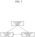
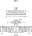
- FIG. 3 is a configuration diagram showing an operation mode of the air purification apparatus according to the first embodiment of the present invention.
- the operation mode of the air purification apparatus 2000 includes a filtering mode, a cleaning mode, and may include an emergency mode.
- the air purifier operates in the filtering mode, the cleaning mode, or the emergency mode.
- the air purification apparatus 2000 purifies polluted air.
- the first filter unit 2120 is cleaned.
- the air purification apparatus 2000 may perform a response operation for the emergency situation.
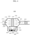
- FIG. 4 is a schematic diagram of the air purification apparatus according to the first embodiment of the present invention, and a schematic diagram of the air purification apparatus operating in the filtering mode.
- the air purification apparatus 2000 operating in the filtering mode may perform a filtering operation of purifying polluted air.
- contaminants is collected in the first filter unit 2120.
- the air purification apparatus 2000 may enter the filtering mode according to a predetermined filtering entry criterion.
- the predetermined filtering entry criterion may be based on an input signal of a manager of the air purification apparatus 2000 or state information on the air purification apparatus 2000.
- the control unit 2200 outputs a signal for controlling the predetermined filtering mode operation of the individual components of the air purification apparatus 2000.
- first opening and closing member 2620 and the second opening and closing member 2640 may be opened.
- the exhaust unit 2520 may induce an air flow from the first main area 2102 to the second main area 2104.
- the fourth opening and closing member 2940 may be closed. Accordingly, in the sub-housing 2800, the air flow generated by the exhaust unit 2520 can be minimized.
- the circulation induction unit 2840 may not operate.
- the heating unit 2850 may not emit heat.
- the relatively polluted air provided to the main housing 2100 is purified by the first filter unit 2120.
- At least a part of the contaminants contained in the air introduced into the main housing 2100 is collected in the first filter unit 2120 as it passes through the first filter unit 2120.
- At least a part of the contaminants contained in the air introduced into the main housing 2100 may be collected in the first filter unit 2120 as it moves in a direction from the first main area 2102 toward the second main area 2104.
- the flow path through which air may at least flow may be provided in the first filter unit 2120, but as the contaminants are accumulated in the first filter unit 2120, at least a part of the provided flow path may be blocked.
- the amount of contaminants collected in the first filter unit 2120 increases, the amount of air flow passing through the first filter unit 2120 may decrease. As the amount of contaminants collected by the first filter unit 2120 performing the filtering operation increases, a difference between a flow rate generated in the inlet 2300 and a flow rate flowing through the outlet 2500 may increase.
- a pressure difference between the areas before and after the first filter unit 2120 may be changed.
- a pressure of the first main area 2102 may be higher than a pressure of the second main area 2104.
- a difference between the pressure of the first main area 2102 and the pressure of the second main area 2104 may increase as air purification proceeds (i.e., as the filtering operation is performed).
- the control unit 2200 may determine whether the first filter of the air purification apparatus 2000 is in an abnormal state.
- control unit 2200 may acquire (or output) first filter abnormality information.
- the control unit 2200 may determine whether the first filter of the air purification apparatus 2000 is in the abnormal state based on any one of the pressure information on the first main area 2102 and the pressure information on the second main area 2104.
- control unit 2200 may determine whether the first filter of the air purification apparatus 2000 is in the abnormal state based on the pressure information on the first main area 2102 and the pressure information on the second main area 2104.
- the control unit 2200 may determine whether the first filter of the air purification apparatus 2000 is in the abnormal state based on the flow rate information on the first main area 2102 and the flow rate information on the second main area 2104.
- the first filter abnormality information may include information on a decrease in the operation performance of the air purification apparatus 2000.
- the first filter abnormality information may include information on the necessity for the cleaning operation of the air purification apparatus 2000.
- the first filter abnormality information may include information on the collection of an excessive amount of contaminants in the first filter unit 2120.
- the communication unit 2600 may transmit the state information on the air purification apparatus 2000 based on the first filter abnormality information, to the main server 1000 or the user terminal 3000.
- At least any one of the first temperature detection unit 2150, the second temperature detection unit 2160, the third temperature detection unit 2880, the fourth temperature detection unit 2890, and the emergency temperature detection unit 2190 may provide the information on the temperature of the air purification apparatus 2000 to the control unit 2200.
- the air purification apparatus 2000 operating in the filtering mode may enter the cleaning mode according to a predetermined cleaning entry criterion.
- the cleaning entry criterion may be based on the input signal of the manager of the air purification apparatus 2000 or the state information on the air purification apparatus 2000, or may relate to a predetermined time reference.
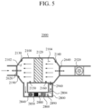
- FIG. 5 is a schematic diagram of the air purification apparatus according to the first embodiment of the present invention, and a schematic diagram of the air purification apparatus operating in the cleaning mode.
- the air purification apparatus 2000 operating in the cleaning mode performs the cleaning operation so that the first filter unit 2120 is cleaned.
- the air purification apparatus 2000 operates in the cleaning mode, at least some of the contaminants collected in the first filter unit 2120 is removed.
- the individual components of the air purification apparatus 2000 may perform a predetermined cleaning mode operation.
- the control unit 2200 outputs a signal for controlling the predetermined cleaning mode operation for the individual components of the air purification apparatus 2000.
- first opening and closing member 2620 and the second opening and closing member 2640 may be closed.
- the first opening and closing member 2620 closes the air flow path provided to the main housing 2100, but may not be in a completely sealed state. Accordingly, even when the first opening and closing member 2620 is in the closed state, at least a small amount of air (i.e., air containing at least a small amount of oxygen) may be introduced into the main housing 2100.
- a small amount of air i.e., air containing at least a small amount of oxygen
- the exhaust unit 2520 may not operate.
- the fourth opening and closing member 2940 may be opened. Accordingly, the second main area 2104 may be fluidically connected to the second circulation flow path unit 2804.
- the circulation induction unit 2840 may induce an air flow. Due to the operation of the circulation induction unit 2840, a circulation flow may be generated within the main housing 2100 and the sub-housing 2800.
- the direction of the above-described circulation flow may be defined by the circulation induction unit 2840.
- the arrows shown in FIG. 5 indicate the direction of the circulation air flow.
- FIG. 5 shows the air flow circulated counterclockwise, the present invention is not limited thereto, and the air may be circulated clockwise according to an embodiment.
- the content related to the cleaning mode will be described based on the air flow circulated counterclockwise, but the present invention is not construed as being limited thereto.
- the heating unit 2850 emits heat.
- the air heated by the heating unit 2850 may be diffused by the above-described circulation flow, and the first filter unit 2120 is heated.
- the heating intensity of the heating unit 2850 may be controlled according to a predetermined criterion.
- the heating unit 2850 When the first filter unit 2120 is heated by the heating unit 2850, at least some of the contaminants collected in the first filter unit 2120 is removed.
- a reaction to the collected contaminants based on the first catalyst may occur.
- a reaction to the collected contaminants may occur.
- the temperature of the first catalyst is higher than or equal to a specific temperature -the specific temperature corresponds to the activation temperature of the first catalyst-, the reaction to the contaminants may proceed.
- the first catalyst may be a catalyst for mediating a cracking reaction to the contaminants collected in the first filter unit 2120.
- the contaminants may be decomposed into a material having a smaller molecular size than before the reaction.
- the temperature of the first filter unit 2120 may be indirectly increased by the heated air whose temperature is increased by the heating unit 2850. Accordingly, it may take a long time for the temperature of the first filter unit 2120 to be sufficiently high (higher than or equal to a temperature at which the contaminants may at least react) with only the heating unit 2850.
- a partial area of the first filter unit 2120 may be heated by the heating reaction occurring in the remaining part of the first filter unit 2120.
- a first surface of the first filter unit 2120 may be heated earlier than a second surface opposite to the first surface.
- a temperature of an area closer to the first surface of the first filter unit 2120 may be first increased with respect to the first surface and the second surface.
- the reaction based on the first catalyst may occur first in the area (which may refer to an area closer to the first surface than the second surface) heated first by the heating unit 2850.
- the reaction based on the first catalyst may be a heating reaction.
- the reaction based on the first catalyst may function as a heat source.
- Heat generated from the reaction based on the first catalyst may be diffused.
- the generated heat may be provided to the main housing 2100 and the sub-housing 2800 along the circulation flow.
- the heat generated due to the heating reaction may heat the area of the first filter unit 2120 adjacent to the second surface and the first main area 2102.
- the area of the first filter unit 2120 adjacent to the second surface and the first main area 2102 may be heated by the heating unit 2850 and the heat generated in the area of the first filter unit 2120 adjacent to the first surface.
- the first filter unit 2120 may include a first filter area and a second filter area.
- the first filter area may refer to an area closer to the first main area 2102 than the second filter area.
- the first filter area may be heated as the heating reaction occurs in the second filter area.
- the temperature of the first filter area may be increased by the heating reaction occurring in the second filter area.
- the control unit 2200 may control the heating intensity of the heating unit 2850 so that the temperature of the second main area 2104 is included in a predetermined temperature range.
- the predetermined temperature range may include the activation temperature of the first catalyst.
- the air purification apparatus 2000 When the air purification apparatus 2000 operates in the cleaning mode, the amount of contaminants accumulated in the first filter unit 2120 can be decreased.
- the amount of contaminants present in the first filter unit 2120 may correspond to pressure information based on at least any one of the pressure of the first main area 2102 and the pressure of the second main area 2104.
- the pressure information may be a difference value between the pressure of the first main area 2102 and the pressure of the second main area 2104.
- the difference between the pressure in the first main area 2102 and the pressure in the second main area 2104 may be decreased.
- the pressure information may be information based on the pressure of the first main area 2102 and a predetermined pressure value. As the pressure of the first main area 2102 is greater than the predetermined pressure value, a larger amount of contaminants may be construed as being collected in the first filter unit 2120.
- the pressure information may be information based on the pressure of the second main area 2104 and the predetermined pressure value. As the pressure of the second main area 2104 is greater than the predetermined pressure value, a larger amount of contaminants may be construed as being collected in the first filter unit 2120.
- the first product may be moved in the main housing 2100 and the sub-housing 2800 along the circulation flow.
- the first product may be provided to the second filter unit 2860.
- the second filter unit 2860 may receive the first product, and the second filter unit 2860 may acquire a second product.
- the second filter unit 2860 may receive the first product and transmit the second product toward the main housing 2100.
- the first product may be provided to the second catalyst coated on the second filter unit 2860.
- the first product may be a reactant for the reaction based on the second catalyst.
- the reaction based on the second catalyst may be a heating reaction.
- the reaction based on the second catalyst may function as a heat source.
- Heat generated from the reaction based on the second catalyst may be diffused.
- the generated heat may be provided to the main housing 2100 and the sub-housing 2800 along the circulation flow.
- a second product may be acquired from the second filter unit 2860.
- the second product may be a material produced by the reaction based on the second catalyst from the first product.
- the second catalyst is a diesel oxidation catalyst (DOC).
- DOC diesel oxidation catalyst
- the first product may be oxidized when the reaction based on the DOC proceeds.
- the first product may be oxidized when the reaction based on the DOC proceeds, and thus the second product may be acquired.
- the second product may be a material relatively harmless to humans compared to the contaminants.
- the second product may contain carbon dioxide (CO 2 ), oxygen (O 2 ), water (H 2 O), nitrogen (N 2 ), and the like.
- the first catalyst may be the cracking catalyst and the DOC.
- the provided contaminants may be a reactant of the cracking reaction mediated by the first catalyst
- the first product may be acquired by the cracking reaction.
- the acquired first product may be a reactant of the DOC mediated by the first catalyst
- the second product may be acquired by the oxidation reaction.
- the second product may be a material harmless to humans compared to the contaminants.
- the second product may contain carbon dioxide (CO 2 ), oxygen (O 2 ), water (H 2 O), nitrogen (N 2 ), and the like.
- the second product may be moved along the circulation flow.
- the second product may be discharged along an opened flow path when the first opening and closing member 2620 or the second opening and closing member 2640 is opened.
- the control unit 2200 may determine whether the second filter of the air purification apparatus 2000 is in an abnormal state. When it is determined that the air purification apparatus 2000 is in a state in which the second filter is abnormal, the control unit 2200 may acquire (or output) second filter abnormality information. Whether the second filter is in the abnormal state may be determined when the cleaning mode is completed (or when the air purification apparatus enters the filtering mode).
- the control unit 2200 may acquire the state information on the air purification apparatus 2000.
- the control unit 2200 may determine whether the second filter of the air purification apparatus 2000 is in the abnormal state based on the acquired state information.
- the state information may be end pressure data.
- the end pressure data may be acquired after the cleaning mode operation is ended. In other words, the end pressure data may be acquired at a time point after the air purification apparatus 2000 enters the filtering mode.
- the end pressure data may be acquired within a predetermined time with respect to the time point when the air purification apparatus 2000 enters the filtering mode.
- the time point when the air purification apparatus 2000 enters the filtering mode may be determined with respect to a time point when the first opening and closing member 2620 and/or the second opening and closing member 2640 are opened.
- the end pressure data may be based on at least any one of the pressure of the first main area 2102 and the pressure of the second main area 2104.
- the pressure of the first main area 2102 may be measured by the first pressure detection unit 2150.
- the pressure of the second main area 2104 may be measured by the second pressure detection unit 2160.
- control unit 2200 may determine that the air purification apparatus 2000 is in the state in which the second filter is abnormal.
- control unit 2200 may determine that the air purification apparatus 2000 is in the state in which the second filter is abnormal.
- control unit 2200 may determine that the cleaning mode operation state of the air purification apparatus 2000 is normal.
- control unit 2200 may acquire the second filter abnormality information.
- the second filter abnormality information may include information indicating that the cleaning of the first filter unit 2120 does not proceed beyond a certain level even when the air purification apparatus 2000 performs the cleaning mode operation.
- the air purification apparatus 2000 may further include an alarm unit which may provide information (or data) based on the second filter abnormality information to the user.
- the alarm unit may provide the user with information based on the second filter abnormality information as visual information or sound information.
- the second filter abnormality information may include information on the necessity for filter replacement or additional cleaning for the air purification apparatus 2000.
- the second filter abnormality information may refer to a case in which a material which may not be reacted based on the first catalyst is accumulated in the first filter unit 2120 by a certain amount or more.
- the information on the necessity for additional cleaning may include high-pressure cleaning request information.
- the additional cleaning may refer to the high-pressure cleaning of the first filter unit 2120.
- the high-pressure cleaning may refer to cleaning the filter through an additional air flow.
- the high-pressure cleaning may refer to removing the contaminants of the first filter unit 2120 using air pressure injected using separate high-pressure pulsed air in addition to the above-described cleaning operation.
- the main housing 2100 may further include a predetermined installation area where the cleaning unit may be provided.
- the cleaning unit may be a high-pressure air injection member which may discharge high-pressure air.
- the predetermined installation area may be positioned on an outer surface of the main housing 2100 corresponding to the second main area 2101.
- the cleaning unit may generate an air flow in a direction from the outlet 2500 toward the inlet 2300.
- the cleaning unit may generate an air flow in a direction from the second main area 2104 toward the first main area 2102.
- the main housing 2100 may further include the high-pressure air injection member.
- the control unit 2200 may acquire the high-pressure cleaning request information or filter replacement request information for the first filter unit 2120 based on the end pressure data.
- the control unit 2200 may acquire the filter replacement request information, when the differential pressure between the pressure of the first main area 2102 and the pressure of the second main area 2104 is greater than or equal to a first threshold, and acquire the high-pressure cleaning request information when the differential pressure between the pressure of the first main area 2102 and the pressure of the second main area 2104 is greater than or equal to a second threshold.
- the second threshold may be smaller than the first threshold.
- the control unit 2200 may acquire the filter replacement request information, when the difference between the pressure of the first main area 2102 and the predetermined pressure is greater than or equal to a third threshold, and acquire the high-pressure cleaning request information when the difference between the pressure of the first main area 2102 and the predetermined pressure is greater than or equal to a fourth threshold.
- the fourth threshold may be smaller than the third threshold.
- the control unit 2200 may acquire the filter replacement request information, when the difference between the pressure of the second main area 2104 and the predetermined pressure is greater than or equal to a fifth threshold, and acquire the high-pressure cleaning request information when the difference between the pressure of the second main area 2104 and the predetermined pressure is greater than or equal to a sixth threshold.
- the sixth threshold may be smaller than the fifth threshold.
- control unit 2200 may determine whether the filter replacement is required based on at least any one of the first main area 2102 and the second main area 2104.
- control unit 2200 may acquire the filter replacement request information.
- control unit 2200 may acquire the filter replacement request information.
- control unit 2200 may acquire the filter replacement request information.
- the communication unit 2600 may transmit to the main server 1000 or the user terminal 3000 the state information on the air purification apparatus 2000 based on the second filter abnormality information.
- the air purification apparatus 2000 operating in the cleaning mode may enter the filtering mode according to a predetermined filtering mode entry criterion.
- the filtering mode entry criterion may be based on the input signal of the manager of the air purification apparatus 2000 or the state information on the air purification apparatus 2000, or may relate to a predetermined time reference.
- FIGS. 6 and 7 are graphs showing data on a temperature of a specific area over time when the air purification apparatus according to the first embodiment of the present invention operates in the cleaning mode in the general cleanable state.
- the general cleanable state may refer to a case in which the cleaning operation efficiency of the air purification apparatus 2000 is higher than or equal to predetermined cleaning efficiency.
- the general cleanable state may be a case in which contaminants are collected in the first filter unit 2120 in a first amount or more.
- the general cleanable state may refer to a state in which the reactant based on the first catalyst is included in the first filter unit 2120 in the first amount or more.
- the general cleanable state may refer to a state in which a material which may not be reacted based on the first catalyst coated on the first filter unit 2120 is collected in the first filter unit 2120 in a certain numerical range or less.
- the first filter unit 2120 may sufficiently include the reactant of the reaction based on the first catalyst.
- a cleaning mode operation section of the air purification apparatus includes a first section 4120, a second section 4130, a third section 4140, a fourth section 4150, a fifth section 4160, a sixth section 4170, and a seventh section 4180 in chronological order.
- a first graph 4112 represents data on the temperature of the second main area 2104 according to the cleaning mode operating time of the air purification apparatus 2000. Information on the temperature of the second main area 2104 may be acquired by the second temperature detection unit 2140.
- a second graph 4114 represents data on the temperature of the first main area 2102 according to the cleaning mode operating time of the air purification apparatus 2000. Information on the temperature of the first main area 2102 is acquired by the first temperature detection unit 2130.
- a third graph 4116 represents temperature data on the heating unit 2850 according to the cleaning mode operating time of the air purification apparatus 2000.
- the temperature data of the heating unit 2850 described below may be data on the temperature of an area adjacent to the heating unit 2850.
- the temperature data of the heating unit 2850 may be data on the temperature of a downstream area of the heating unit 2850 with respect to the air flow direction. Data on the temperature of the heating unit 2850 may be acquired by the third temperature detection unit 2880 or the fourth temperature detection unit 2890.
- the temperature data of the heating unit 2850 may also be data on the temperature of the heating unit itself and may also be data on a temperature calculated by a voltage applied to the heating unit 2850.
- the first main area 2102 may be a downstream area of the first filter unit 2120 with respect to the air flow direction induced by the circulation induction unit 2840.
- the first main area 2102 may be an area farther away from the heating unit 2850 than the second main area 2104 with respect to the circulation flow path.
- the first section 4120 may be divided from the second section 4130 with respect to the time point when the temperature of the heating unit 2850 is controlled.
- the first section 4120 and the second section 4130 may also be divided with respect to the time point when the heating unit 2850 outputs a temperature higher than or equal to a certain temperature.
- the second section 4130 may be divided from the third section 4140 with respect to a first division time point 4132.
- the first graph 4112 may include the first division time point 4132.
- a temperature change rate of the first graph 4112 may be different before and after the first division time point 4132.
- the division time point defined in the present invention is construed to refer to a time point when the degree of temperature change (or speed) is different before and after the division time point unless otherwise specified.
- the third section 4140 is divided from the fourth section 4150 based on a second division time point 4142.
- the second graph 4114 may include the second division time point 4142.
- a temperature change rate of the second graph 4114 is different before and after the second division time point 4142.
- the fourth section 4150 may be divided from the fifth time point 4160 with respect to a time point when the temperature of the first graph 4112 is maximum.
- the fifth section 4160 may be divided from the sixth section 4170 with respect to a time point when the temperature of the second graph 4114 is maximum.
- the sixth section 4170 may be divided from the seventh section 4180 with respect to a time point when the heating intensity of the heating unit 2850 is controlled.
- the temperature of the heating unit 2850 may be increased.
- the temperature of the first main area 2102 and the temperature of the second main area 2104 may be increased by the heating unit 2850.
- a temperature increase rate of the second main area 2104 may be greater than a temperature increase rate of the first main area 2102. This may be because the second main area 2104 is closer to the heating unit 2850 than the first main area 2102 with respect to the air flow direction.
- the heating unit 2850 may function as a sole heat source. In other words, the reaction based on the first catalyst coated on the first filter unit 2120 may not occur.
- the temperature data of the heating unit 2850 may be within a predetermined range.
- the temperature data of the heating unit 2850 may be kept constant.
- the temperature of the first main area 2102 and the temperature of the second main area 2104 may be increased.
- the temperature increase rate of the second main area 2104 may be greater than the temperature increase rate of the first main area 2102.
- the reaction based on the first catalyst coated on the first filter unit 2120 may occur.
- the generated reaction based on the first catalyst may occur in a partial area of the first filter unit 2120 adjacent to the second main area 2104.
- the reaction based on the second catalyst coated on the second filter unit 2860 may occur.
- the first division time point 4132 may be positioned between the second section 4130 and the third section 4140.
- the first division time point 4132 is generated when the reaction proceeds in the first filter unit 2120.
- the first division time point 4132 is after the time point when the reaction based on the first catalyst coated on the first filter unit 2120 starts.
- the first division time point 4132 may correspond to the time point when the reaction starts in an area adjacent to the second main area 2104 of the first filter unit 2120.
- the heat-generation of the heating unit 2850 functions as a heat source, and after the first division time point 4132, the heat-generation of the heating unit 2850 and the heating reaction in the first filter unit 2120 may function as a heat source.
- the control unit 2200 may determine whether the cleaning of the first filter unit 2120 has been started based on the data on the temperature of the second main area 2104.
- the control unit 2200 determines that the cleaning of the first filter unit 2120 has been started when the first graph 4112 includes the first division time point 4132.
- the control unit 2200 may output cleaning start information.
- the cleaning start information may include information on the fact that the cleaning of the first filter unit has been started (or the reaction to the contaminant has been started).
- the communication unit 2600 may transmit to the main server 1000 or the user terminal 3000 information indicating that the cleaning operation for the air purification apparatus 2000 has been started.
- the heat-generation of the heating unit 2850 may be controlled at a time point corresponding to the first division time point 4132. At the first division time point 4132, the heating intensity of the heating unit 2850 may be decreased. Alternatively, the heat-generation of the heating unit 2850 may be ended at the first division time point 4132.
- the temperature of the first main area 2102 and the temperature of the second main area 2104 may be increased even when the heating intensity of the heating unit 2850 is decreased (or even when the heat-generation of the heating unit is ended).
- the amount of heat generated by the heating reaction may be greater than the amount of heat generated by the heating unit 2850.
- the temperature of the first main area 2102 and the temperature of the second main area 2104 may be increased.
- the temperature data of the heating unit 2850 may be kept constant.
- the reaction based on the first catalyst may occur.
- the reaction based on the second catalyst may occur.
- the heat generated by the reaction based on the first catalyst and the heating unit 2850 may function as a heat source.
- the heat generated by the reaction based on the second catalyst may also function as a heat source.
- the temperature of the second main area 2104 may be increased by the heating reaction occurring in the first filter unit 2120 in the area adjacent to the second main area 2104 and the heat-generation of the heating unit 2850.
- the temperature of the first main area 2102 may be increased by the heat generated by the heating unit 2850.
- the second division time point 4142 may be positioned between the third section 4140 and the fourth section 4150.
- the second division time point 4142 may be generated when the reaction proceeds in the first filter unit 2120.
- the second division time point 4142 may correspond to the time point when the reaction starts in the area adjacent to the first main area 2102 of the first filter unit 2120.
- the reaction may be construed as occurring in the area of the first filter unit 2120 adjacent to the first main area 2102 (i.e., cleaning proceeds).
- Heat due to the heating reaction in the area of the first filter unit 2120 adjacent to the second main area 2104 may be diffused along the air flow within the main housing 2100. At this time, the diffused heat may heat the remaining area of the first filter unit 2120.
- the first activation temperature refers to an activation temperature of the first catalyst-
- an area of the first filter unit 2120 which does not reach the first activation temperature may be heated by the heat generated by the reaction which occurs in the area of the first filter unit 2120 having already reached the first activation temperature.
- the first filter unit 2120 may include a first area of the first filter unit 2120 reaching the first activation temperature at the first time point within the third section 4140 and a second area not reaching the first activation temperature at the first time point.
- the second area may be heated by the heat generated by the reaction occurring in the first area.
- both a temperature of the first area and a temperature of the second area may be higher than or equal to the first activation temperature.
- An interval between the second time point and the first time point may be shorter due to the reaction based on the first catalyst.
- the control unit 2200 determines whether the cleaning of the first filter unit 2120 has been started based on the data on the temperature of the first main area 2102.
- the control unit 2200 may determine that the cleaning of the first filter unit 2120 has been started when the second graph 4114 includes the second division time point 4142.
- the control unit 2200 may output cleaning start information when it is determined that the cleaning of the first filter unit 2120 has been started.
- the communication unit 2600 may transmit to the main server 1000 or the user terminal 3000 the information indicating that the cleaning operation for the air purification apparatus has been started.
- the temperature of the first main area 2102 and the temperature of the second main area 2104 may be increased.
- the temperature data of the heating unit 2850 may be kept constant.
- the heat source of the first main area 2102 may be the heating reaction occurring in the first filter unit 2120 and/or the second filter unit 2860 and the heating unit 2850.
- the heat source of the second main area 2104 may be the heating reaction occurring in the first filter unit 2120 and/or the second filter unit 2860 and the heating unit 2850.
- the temperature of the second main area 2104 may be higher than the temperature of the heating unit 2850.
- contaminants may be sufficiently collected in the first filter unit 2120 (i.e., a reactant for the first catalyst may be sufficiently present). Accordingly, a sufficiently large amount of reaction occurs in the first filter unit 2120, and thus a large amount of the first product may be acquired as a result of the reaction to the contaminants.
- the acquired first product is a reactant to the second filter unit 2860, and a sufficiently large amount of reaction may occur in the second filter unit 2860.
- the heat generated by the reaction may increase the temperature of the second main area 2104. As a result, the temperature of the second main area 2104 may reverse the temperature data of the heating unit 2850.
- the temperature increase rate of the second main area 2104 may be greater than the temperature increase rate of the first main area 2102. This is because in the fourth section 4150, the reaction actively occurs in the second filter unit 2860, and the second main area 2104 is closer to the second filter unit 2860 than the first main area 2102 with respect to the air flow. In other words, the heat generated by the second filter unit 2860 (due to the reaction) may have a greater effect on the second main area 2104 than on the first main area 2102.
- the information on the temperature data in the third section 4140 may be different from the information on the temperature data in the fourth section 4150. This may be because the heat sources of the first main area 2102 are different from each other before and after the second division time point 4142.
- the third section 4140 may include a first division adjacent section adjacent to the second division time point 4142 and having a predetermined time range
- the fourth section 4150 may include a second division adjacent section adjacent to the second division time point 4142 and having a predetermined time range.
- an average temperature increase rate of the first main area 2102 in the first division adjacent section may be smaller than an average temperature increase rate of the first main area 2102 in the second division adjacent section.
- the relationship between the temperature of the first main area 2102 and the temperature of the second main area 2104 in the third section 4140 may be different from the relationship between the temperature of the first main area 2102 and the temperature of the second main area 2104 in the fourth section 4160.
- the effect of the heating reaction based on the first catalyst on the second main area 2104 may be relatively smaller than the effect of the heating reaction based on the first catalyst on the first main area 2102.
- a ratio of the average increase rate of the first main area 2102 in the fourth section 4160 to the average temperature increase rate of the first main area 2102 in the third section 4140 may be greater than a ratio of the average temperature increase rate of the second main area 2104 in the fourth section 4160 to the average temperature increase rate of the second main area 2104 in the third section 4140.
- the temperature of the second main area 2104 may be decreased, and the temperature of the first main area 2102 may be increased. At this time, the temperature data of the heating unit 2850 may be kept constant.
- the scale of the reaction occurring in the second filter unit 2860 may be decreased.
- the scale of the reaction occurring in the first filter unit 2120 may be decreased.
- the temperature of the first main area 2102 and the temperature of the second main area 2104 may be decreased.
- the scale of the reaction occurring in the second filter unit 2860 may be decreased.
- the scale of the reaction occurring in the first filter unit 2120 may be decreased.
- the temperature data of the heating unit 2850 may be kept constant.
- the cleaning of the first filter unit 2120 may be sufficiently performed until any time point before the sixth section 4170. (At least any time point, the reaction to the contaminants may no longer proceed or a reaction of a scale which is smaller than or equal to a predetermined scale may occur)
- the temperature of the first main area 2102 and/or the temperature of the second main area 2104 may be gradually decreased. (Referring to FIG. 6 , the temperature of each area in the sixth section is slowly decreased compared to the other sections) This is because the first main area 2102 and/or the second main area 2104 are heated by the heat emitted by the heated first filter unit 2120.
- the heating intensity of the heating unit 2850 may be controlled. At the time point of entering the seventh section 4180, the heating intensity of the heating unit 2850 may be decreased or the heat-generation of the heating unit 2850 may be ended.
- the temperature of the second main area 2104 may be rapidly decreased.
- the effect of the change in the heating intensity of the heating unit 2850 on the first main area 2102 may be insignificant compared to the second main area 2104.
- FIGS. 8 and 9 are graphs showing temperature data before and after the second filter unit of the air purification apparatus according to the first embodiment of the present invention.
- the temperature data on the area before and after the second filter unit 2860 shown in FIG. 8 may be temperature data at a time point when the reaction based on the second catalyst is not started.
- the temperature data shown in FIG. 8 may be temperature data of at least any one of the first section 4120 and the second section 4130 described above with reference to FIG. 6 .
- the temperature data on the area before and after the second filter unit 2860 shown in FIG. 9 may be temperature data after a time point when the reaction based on the second catalyst starts at least.
- the temperature data shown in FIG. 9 may be temperature data of at least any one of the second section 4130, the third section 4140, and the fourth section 4150 described above with reference to FIG. 6 .
- the sub-housing 2800 may include a first point 4402, a second point 4404, and a third point 4406.
- the first point 4402 may be positioned in an upstream area of the heating unit 2850 with respect to the circulation flow direction.
- the second point 4402 may be positioned between the heating unit 2850 and the second filter unit 2860. Information on a temperature of the second point 4404 may be acquired by the third temperature detection unit 2880.
- the third point 4406 may be positioned in a downstream area of the second filter unit 2860 with respect to the circulation flow direction. Information on a temperature of the third point 4406 may be acquired by the fourth temperature detection unit 2890.
- FIG. 8 is a view showing data on the temperature within the sub-housing 2800 when the air purification apparatus 2000 is operating in the cleaning mode and no reaction occurs in the second filter unit 2860.
- a point having the highest temperature within the sub-housing 2800 may be positioned between the first point 4402 and the second point 4404. At this time, the highest temperature point may be positioned in a downstream area adjacent to the heating unit 2850 with respect to the circulation flow direction.
- a temperature of the third point 4406 may be at least lower than a temperature of the second point 4404.
- the temperature of the second catalyst -the second catalyst is coated on the second filter unit 2680- is lower than the activation temperature of the second catalyst, the temperature of the third point 4406 may be lower than the temperature of the second point 4404.
- the heat source of the second point 4404 and the third point 4406 may be the heating unit 2850.
- FIG. 9 is a view showing data on the temperature within the sub-housing 2800 when the air purification apparatus 2000 is operating in the cleaning mode and the reaction occurs in the second filter unit 2860.
- the heat generated by the heating reaction may function as a heat source.
- the heat generated by the heating reaction may be diffused along the circulation flow.
- the heat source of the third point 4406 may be heat due to the heat generated by the heating unit 2850 and the heating reaction occurring in the second filter unit 2860.
- the heat due to the heating reaction occurring in the second filter unit 2860 may have a greater effect on the downstream area of the circulation flow than on the upstream area of the circulation flow.
- the heat generated by the reaction based on the second catalyst may function as a greater heat source at the second point 4404 than at the third point 4406.
- a temperature of at least a part of the third point 4406 may be higher than the temperature of the second point 4404. According to one example, at least a part of the third point 4406 may be higher than a temperature of a point very adjacent to the heating unit 2850.
- the temperature of the second point 4404 may be lower than the temperature of the third point 4406 even when the second point 4404 is closer to the heating unit 2805 than the third point 4406.
- the control unit 2200 may determine that the cleaning of the first filter unit 2120 has been ended according to a predetermined cleaning end criterion. When it is determined that the cleaning of the first filter unit 2120 has been ended, the control unit may acquire (or output) cleaning end information.
- control unit 2200 may determine that the cleaning of the first filter unit 2120 has been ended.
- control unit 2200 may determine that the cleaning of the first filter unit 2120 has been ended.
- control unit 2200 may determine that the cleaning of the first filter unit 2120 has been ended.
- control unit 2200 may determine that the cleaning of the first filter unit 2120 has been ended.
- control unit 2200 may determine that the cleaning of the first filter unit 2120 has been ended.
- control unit 2200 may determine that the cleaning of the first filter unit 2120 has been ended.
- control unit 2200 may determine that the cleaning of the first filter unit 2120 has been ended.
- the heat-generation of the heating unit 2850 may be ended.
- the cleaning end information may include information on the fact that cleaning of the first filter unit has been ended.
- the communication unit 2600 may transmit to the main server 1000 or the user terminal 3000 information indicating that the cleaning operation of the air purification apparatus has been ended.
- the heat-generation of the heating unit 2850 may be ended when the control unit 2200 acquires the cleaning end information.
- the air purification apparatus 2000 may enter the filtering mode from the cleaning mode according to a predetermined criterion.
- the communication unit 2600 may transmit the filtering mode entry related data to the main server 1000 or the user terminal 3000.
- the air purification apparatus 2000 may enter the filtering mode when the temperature of the main housing 2100 or the sub-housing 2800 is lower than or equal to a mode switching temperature.
- the control unit 2200 may acquire filter normal operation information when the air purification apparatus 2000 is in a normal cleanable state after the above-described cleaning operation is performed.
- the communication unit 2600 may transmit to the main server 1000 or the user terminal 3000 state information on the air purification apparatus 2000 including the filter normal operation information.
- the communication unit 2600 may transmit data on a temperature during the cleaning mode operation of the air purification apparatus 2000 in a normal state.
- the air purification apparatus 2000 may include the adsorption unit 2540, and the particulate matter may be accumulated in the adsorption unit 2540 while the air purification apparatus 2000 operates in the filtering mode.
- the adsorption unit 2540 may be cleaned when the air purification apparatus 2000 enters the filtering mode.
- the adsorption unit 2540 may be cleaned by the air provided (or heat of the air provided) from the main housing 2100.
- a temperature of the air provided from the main housing 2100 may need to be higher than or equal to a predetermined adsorption cleaning temperature.
- the mode switching temperature may be at least higher than the adsorption cleaning temperature.
- the individual components of the air purification apparatus 2000 may perform the predetermined operations described above with reference to FIG. 4 .
- FIG. 10 is a graph showing data on a temperature of a specific area over time when the air purification apparatus according to the first embodiment of the present invention operates in the cleaning mode in an excessively cleanable state.
- the excessively cleanable state may be a case in which contaminants are collected in the first filter unit 2120 in a second amount or more.
- the excessively cleanable state may refer to a state in which the reactant based on the first catalyst is included in the first filter unit 2120 in the second amount or more.
- the second amount refers to the general cleanable state and may have a larger value than the above-described first amount.
- the excessively cleanable state may refer to a state in which the reactant of the reaction mediated by the first catalyst is excessively collected in the first filter unit 2120.
- the air purification apparatus in the excessively cleanable state and the air purification in the general cleanable state may be divided based on the graph showing the temperature according to the cleaning operation.
- a cleaning mode operation section of the air purification apparatus includes a first section 4220, a second section 4230, a third section 4240, a fourth section 4250, a fifth section 4260, a sixth section 4270, and a seventh section 4280 in chronological order.
- a first graph 4212 represents data on the temperature of the second main area 2104 according to the cleaning mode operating time of the air purification apparatus 2000.
- a second graph 4214 represents data on the temperature of the first main area 2102 according to the cleaning mode operating time of the air purification apparatus 2000.
- a third graph 4216 represents temperature data on the heating unit 2850 according to the cleaning mode operating time of the air purification apparatus 2000.
- the first section 4220 may be divided from the second section 4230 with respect to the time point when the temperature of the heating unit 2850 is controlled.
- the first section 4220 and the second section 4230 may be divided with respect to the time point when the heating unit 2850 outputs a temperature which is higher than or equal to a predetermined temperature.
- the second section 4230 is divided from the third section 4240 with respect to a second division time point 4232.
- the second graph 4214 includes the second division time point 4232.
- a temperature change rate of the second graph 4214 is different before and after the second division time point 4232.
- the third section 4240 may be divided from the fourth section 4250 with respect to a first division time point 4242.
- the first graph 4212 may include the first division time point 4242.
- a temperature change rate of the first graph 4212 may be different before and after the first division time point 4242.
- the fourth section 4250 may be divided from the fifth section 4260 with respect to a time point when the temperature of the first graph 4212 is maximum.
- the fifth section 4260 may be divided from the sixth section 4270 with respect to a time point when the temperature of the second graph 4214 is maximum.
- the sixth section 4270 may be divided from the seventh section 4280 with respect to a time point when the heating intensity of the heating unit 2850 is controlled.
- the temperature data of the heating unit 2850 may be increased.
- the temperature of the first main area 2102 and the temperature of the second main area 2104 may be increased by being heated by the heating unit 2850.
- the temperature data of the heating unit 2850 may be kept constant.
- the temperature of the first main area 2102 and the temperature of the second main area 2104 may be increased by being heated by the heating unit 2850.
- the temperature of the second main area 2104 may be a first temperature T1.
- the temperature of the first main area 2102 may be a second temperature T2.
- control unit 2200 may determine that cleaning of the first filter unit 2120 has been started.
- whether to start cleaning may be determined depending on whether the graph on the temperature of the second main area 2104 has the division time point, but even when the division time point is not included, it is determined that the cleaning of the first filter unit 2120 has been started when the temperature of the second main area 2104 is higher than or equal to the predetermined temperature.
- control unit 2200 may determine that the cleaning of the first filter unit 2120 has been started.
- the control unit may acquire cleaning start information when it is determined that the cleaning of the air purification apparatus 2000 (i.e., of the first filter unit 2120) has been started.
- the heat-generation of the heating unit 2850 may be controlled at a time point having the first temperature. At a time point corresponding to the first temperature, the heating intensity of the heating unit 2850 may be decreased.
- the heat-generation of the heating unit 2850 may be controlled at a time point having the second temperature. At a time point corresponding to the second temperature, the heating intensity of the heating unit 2850 may be decreased.
- the control unit 2200 may control the heating intensity of the heating unit 2850 with respect to the division time point.
- the control unit 2200 may determine that the cleaning of the first filter unit 2120 has been started.
- the first temperature may correspond to the activation temperature of the first catalyst.
- the first filter unit 2120 positioned downstream of the second main area 2104 may be heated to be higher than the activation temperature of the first catalyst.
- the reaction based on the first catalyst may occur in at least a part of the first filter unit 2120.
- the technical characteristics of the second division time point 4232 may be substantially the same as those of the second division time point 4142 described above with reference to FIG. 6 .
- the temperature data of the heating unit 2850 may be kept constant.
- the temperature of the first main area 2102 and the temperature of the second main area 2104 may be increased.
- the reaction based on the first catalyst and/or the reaction based on the second catalyst may function as the heat sources for the above-described areas.
- the first division time point 4242 may be positioned between the third section 4240 and the fourth section 4250.
- the first division time point 4242 may occur when the reaction based on the second catalyst occurs.
- the temperature data of the heating unit 2850 may be kept constant. At this time, the temperature of the first main area 2102 and the temperature of the second main area 2104 may be increased.
- the temperature data of the heating unit 2850 may be kept constant.
- the temperature of the first main area 2102 may be decreased.
- the temperature of the second main area 2104 may be increased.
- the temperature of the first main area 2102 may reverse the temperature of the second main area 2104.
- control unit 2200 may determine that the cleaning of the first filter unit 2120 has been started.
- the temperature of the first main area 2102 may be higher than the temperature of the heating unit 2850.
- the contaminants may be excessively collected in the first filter unit 2120 (i.e., the reactant to the first catalyst is excessively present).
- the first filter unit 2120 an excessively large amount of reaction may occur in the first filter unit 2120, and the first product may be acquired as the reaction to the contaminants proceeds.
- the first catalyst may partially function as the DOC.
- the acquired first product may be oxidized to acquire the second product.
- a predetermined reaction and oxidation reaction for acquiring the first product may proceed in the first filter unit 2120.
- the second product in the excessively cleanable state, the second product may be acquired from the first filter unit 2120 unlike the general cleanable state. Accordingly, compared to the general cleanable state, less the first product may be provided to the second filter unit 2860 in the excessively cleanable state.
- the first product may be the reactant of the reaction based on the second catalyst coated on the second filter unit 2860.
- the amount of reaction occurring in the second filter unit 2860 in the excessively cleanable state may be smaller than the amount of reaction occurring in the second filter unit 2860 in the general cleanable state.
- the first main area 2102 may be farther spaced apart from the second filter unit 2860 than the second main area 2104. Accordingly, the amount of reaction occurring in the second filter unit 2860 decreased in the excessively cleanable state may have a greater effect on the second main area 2104 than on the first main area 2102.
- the amount of reaction occurring in the first filter unit 2120 increased in the excessively cleanable state may have a greater effect on the first main area 2102 than the second main area 2104.
- the predetermined reaction and the oxidation reaction are the heating reactions, and may increase the temperature of the first main area 2102 positioned in the downstream area of the first filter unit 2120 with respect to the air flow direction.
- the temperature of the first main area 2102 may reverse the temperature data of the heating unit 2850.
- the temperature data of the heating unit 2850 may be decreased.
- the heat-generation of the heating unit 2850 may be ended.
- the temperature of the first main area 2102 and the temperature of the second main area 2104 may be decreased.
- the temperature of the second main area 2104 may be rapidly decreased compared to the temperature of the first main area 2102. This may be because the first main area 2102 is positioned to be farther spaced apart from the second filter than the second main area 2104 with respect to the air flow.
- the temperature of the first main area 2102 may be lower than the temperature of the second main area 2104.
- control unit 2200 may determine that the cleaning of the first filter unit 2120 has been ended.
- the temperature of the first main area 2102 and the temperature of the second main area 2104 may be decreased. Due to the heat of the first filter heated in the above-described section, the temperature of the first main area 2102 may be smoothly decreased compared to the temperature of the second main area 2104.
- the air purification apparatus 2000 may enter the filtering mode according to the predetermined filtering mode entry criterion.
- the abnormal cleanable state in relation to the cleaning mode operation of the air purification apparatus, the abnormal cleanable state will be described in detail.
- the contents related to the abnormal cleanable state the contents overlapping with the contents described with respect to the general cleanable state and the excessively cleanable state may be omitted, and the contents related to the abnormal cleanable state should be construed in consideration of the above description.
- the cleaning of the first filter unit 2120 may not be sufficiently performed.
- the abnormal cleanable state may be a case in which the amount of contaminants collected in the first filter unit 2120 is less than a certain range.
- the abnormal cleanable state may refer to a state in which the reactant based on the first catalyst coated on the first filter unit 2120 is included less than a predetermined amount in the first filter unit 2120.
- the abnormal cleanable state may be a case in which a material that may not be reacted based on the first catalyst coated on the first filter unit 2120 is collected in the first filter unit 2120 in a certain numerical range or more.
- the air purification apparatus in the abnormal cleanable state and the air purification apparatus in the normal cleanable state may be divided with respect to the graph showing the temperature according to the cleaning operation.
- FIG. 11 is a graph showing data on a temperature of a specific area over time when the air purification apparatus according to the first embodiment of the present invention operates in the cleaning mode in the abnormal cleanable state.
- an operation section of the cleaning mode of the air purification apparatus 2000 in the abnormal cleanable state includes a first section 4320, a second section 4330, a third section 4340, a fourth section 4350, a fifth section 4360, and a sixth section 4370 in chronological order.
- a first graph 4312 represents the data on the temperature of the second main area 2104 according to the cleaning mode operating time of the air purification apparatus (in the abnormal cleanable state).
- a second graph 4314 represents the data on the temperature of the first main area 2102 according to the cleaning mode operating time of the air purification apparatus (in the abnormal cleanable state).
- a third graph 4316 represents the data on the temperature of the heating unit 2850 according to the cleaning mode operating time of the air purification apparatus 2000.
- the first section 4320 may be divided from the second section 4330 with respect to a time point when the temperature data of the heating unit 2850 is constantly controlled.
- the first section 4320 and the second section 4330 may be divided with respect to the time point when the heating unit 2850 outputs a temperature which is higher than or equal to a predetermined temperature.
- the second section 4330 may be divided from the third section 4340 with respect to a first division time point 4332.
- the third section 4340 may be divided from the fourth section 4350 with respect to the maximum time point of the temperature data of the first graph 4312.
- the fourth section 4350 and the fifth section 4360 may be divided with respect to the maximum time point of the temperature data of the second graph 4314.
- the fifth section 4360 may be divided from the sixth section 4370 with respect to the time point when the heating intensity of the heating unit 2850 is controlled.
- the temperature data of the heating unit 2850 may be increased.
- the temperature of the first main area 2102 and the temperature of the second main area 2104 may be increased by being heated by the heating unit 2850.
- the temperature data of the heating unit 2850 may be kept constant.
- the temperature of the first main area 2102 and the temperature of the second main area 2104 may be increased by being heated by the heating unit 2850.
- the temperature of the second main area 2104 may be a first temperature T1.
- the temperature of the first main area 2102 may be a second temperature T2.
- the first temperature may be higher than the second temperature.
- the control unit 2200 may determine that the cleaning of the first filter unit 2120 has been started.
- the control unit 2200 may determine that the cleaning of the first filter unit 2120 has been started.
- At least any time point of the second section 4330, the reaction based on the first catalyst may occur in the first filter unit 2120.
- the first division time point 4332 is present when the reaction occurs in the first filter unit 2120.
- the control unit 2200 determines that the cleaning of the first filter unit 2120 has been started when the first division time point 4332 is generated.
- the heating intensity of the heating unit 2850 may be controlled at a time point corresponding to the first division time point 4332.
- the temperature data of the heating unit 2850 may be kept constant. At this time, the temperature of the first main area 2102 and the temperature of the second main area 2104 may be increased.
- the temperature data of the heating unit 2850 may be kept constant. At this time, the temperature of the first main area 2102 may be decreased. The temperature of the second main area 2104 may be increased.
- the temperature data of the heating unit 2850 may be kept constant. At this time, the temperature of the first main area 2102 and the temperature of the second main area 2104 may be decreased.
- the temperature data of the heating unit 2850 may be decreased.
- the heat-generation of the heating unit 2850 may be ended.
- the temperature of the first main area 2102 and the temperature of the second main area 2104 may be decreased.
- the air purification apparatus 2200 may enter the filtering mode according to the predetermined filtering mode entry criterion.
- the cleaning impossible state in relation to the cleaning mode operation of the air purification apparatus, the cleaning impossible state will be described in detail.
- the contents related to the cleaning impossible state the contents overlapping with the contents related to the general cleanable state, the excessively cleanable state, and the abnormal cleanable state may be omitted, and the contents related to the cleaning impossible state should be construed in consideration of the above description.
- the cleaning of the first filter unit 2120 may be performed in a very small amount or may not be performed.
- the cleaning impossible state may be a case in which a material which may not be reacted based on the first catalyst coated on the first filter unit 2120 is collected in the first filter unit 2120 in a certain numerical range or more.
- the cleaning impossible state may be a case in which contaminants are solidified in the first filter unit 2120 (due to cooling in winter or the like).
- the air purification apparatus in the cleaning impossible state and the air purification apparatus in the general cleanable state may be divided with respect to the graph showing the temperature according to the cleaning operation.
- FIG. 12 is a graph showing data on a temperature of a specific area over time when the air purification apparatus according to the first embodiment of the present invention operates in the cleaning mode in the cleaning impossible state.
- an operation section of the cleaning mode of the air purification apparatus 2000 in the cleaning impossible state includes a first section 4420, a second section 4430, and a third section 4440 in chronological order.
- a first graph 4412 represents data on the temperature of the second main area 2104 according to the cleaning mode operating time of the air purification apparatus (in the cleaning impossible state).
- a second graph 4414 represents data on the temperature of the first main area 2102 according to the cleaning mode operating time of the air purification apparatus (in the cleaning impossible state).
- a third graph 4416 is a graph showing the temperature data of the heating unit 2850 according to the cleaning mode operating time of the air purification apparatus (in the cleaning impossible state).
- the first section 4420 may be divided from the second section 4430 with respect to a time point when the temperature data of the heating unit 2850 is constantly controlled.
- the first section 4420 and the second section 4430 may be divided with respect to the time point when the heating unit 2850 outputs a temperature which is higher than or equal to a predetermined temperature.
- the second section 4430 may be divided from the third section 4440 at a time point when the heating intensity of the heating unit 2850 is controlled.
- the temperature of the first main area 2102 and the temperature of the second main area 2104 may be increased by being heated by the heating unit 2805. At this time, the temperature data of the heating unit 2805 may be increased.
- the temperature of the first main area 2102 and the temperature of the second main area 2104 may be increased by being heated by the heating unit 2805. At this time, the temperature data of the heating unit 2805 may be kept constant.
- the reaction based on the first catalyst provided to the first filter unit 2120 may not occur.
- the reaction based on the second catalyst provided to the second filter unit 2860 may not occur.
- the temperature of the first main area 2102 may not be increased to a first cleanable temperature or higher.
- the temperature of the second main area 2104 may not be increased to a second cleanable temperature or higher.
- the first cleanable temperature may be different from the second cleanable temperature.
- the control unit 2200 may determine that the cleaning of the first filter unit 2120 has not started based on that a predetermined division point is not included in the first graph 4412 and the second graph 4414.
- the control unit 2200 may determine that the cleaning of the first filter unit 2120 does not proceed when the division point for the first graph 4412 and the second graph 4414 is not generated within a predetermined time.
- the control unit 2200 may determine that the cleaning has been ended after a predetermined time with respect to the time point when the operation of the air purification apparatus 2000 in the cleaning mode starts.
- the control unit 2200 may determine that the cleaning of the first filter unit 2120 has been ended after a predetermined time with respect to the time point when the heat-generation of the heating unit 2850 starts.
- the control unit 2200 may determine that the cleaning of the first filter unit 2120 has been ended after the predetermined time with respect to the time point when the temperature of the heating unit 2850 is kept constant (or a case of belonging to a certain range may also be included).
- the heat-generation of the heating unit 2850 may be ended.
- the temperature of the first main area 2102 and the temperature of the second main area 2104 may be decreased as the heating intensity of the heating unit 2850 is controlled (or as the heat-generation of the heating unit 2850 is ended).
- the control unit 2200 may acquire information on the cleaning impossible state when the cleaning is ended without performing an operation of determining that the cleaning of the air purification apparatus 2000 has been started.
- the communication unit 2600 may transmit to the main server 1000 or the user terminal 3000 information including that the air purification apparatus 2000 is in the cleaning impossible state.
- an emergency mode which is another operation mode of the air purification apparatus 2000 according to the first embodiment, will be described in detail below.
- the air purification apparatus 2000 may operate in the emergency mode.
- the air purification apparatus 2000 may operate in the emergency mode when an emergency situation occurs.
- the emergency situation as defined herein may refer to an abnormal situation including a fire occurrence situation, a fire dangerous situation, a situation where an area to be detected is in an abnormally high-temperature state, or the like.
- the emergency mode may include a first emergency mode and a second emergency mode.
- power supply to at least some components of the air purification apparatus 2000 may be cut off.
- the air purification apparatus 2000 may perform a predetermined operation according to a place where the emergency situation occurs.
- FIG. 13 is a flowchart showing a first emergency operation method of the air purification apparatus according to the first embodiment of the present invention.
- the first emergency operation method of the air purification apparatus 2000 may include an operation of acquiring information on a temperature of the air purification apparatus from a temperature detection unit (S4200), an operation of outputting a first emergency operation signal based on the information on the temperature of the air purification apparatus (S4400), and an operation of performing a first emergency operation by the air purification apparatus (S4600).
- the information on the temperature of the air purification apparatus 2000 may be acquired.
- control unit 2200 may acquire the temperature data of the air purification apparatus 2000 from at least any one of the first temperature detection unit 2130, the second temperature detection unit 2140, the third temperature detection unit 2880, the fourth temperature detection unit 2890, and the emergency temperature detection unit 2190.
- FIG. 14 is a configuration diagram showing a separate power supply path to the emergency temperature detection unit of the air purification apparatus according to the first embodiment of the present invention.
- the power supply unit 2400 may include a first power supply unit 2420 and a second power supply unit 2440.
- the emergency temperature detection unit 2190 may acquire the information on the temperature of the area within the air purification apparatus 2000 even when the operations of the first to fourth temperature detection units 2130, 2140, 2880, and 2890 are stopped due to the emergency situation.
- the first power supply unit 2420 may apply power to any one of the individual components of the air purification apparatus 2000 even when the second power supply unit 2440 is inoperable.
- the second power supply unit 2440 may apply power to any one of the individual components of the air purification apparatus 2000 even when the first power supply unit 2420 is inoperable.
- the first power supply unit 2420 may apply power to at least any one of the first to fourth temperature detection units 2130, 2140, 2880, and 2890.
- the second power supply unit 2440 may apply power to the emergency temperature detection unit 2190.
- the control unit 2200 may acquire the information on the temperature of the air purification apparatus 2000 from the emergency temperature detection unit 2190 even when the first to fourth temperature detection units 2130, 2140, 2880, and 2890 may not acquire the information on the temperature of the air purification apparatus 2000.
- the operation of outputting the first emergency operation signal based on the information on the temperature of the air purification apparatus (S4400) may be performed.
- control unit 2200 may determine whether the air purification apparatus 2000 is in the emergency situation based on the acquired temperature data.
- the control unit 2200 may determine that the air purification apparatus 2000 is in the emergency situation when the temperature of at least a partial area in the air purification apparatus 2000 is higher than or equal to a predetermined emergency temperature.
- the control unit 2200 may output the first emergency operation signal.
- the performing of the first emergency operation by the air purification apparatus 2000 may be performed.
- the air purification apparatus 2000 may perform the first emergency operation according to the input provided from the user.
- the air purification apparatus 2000 may enter the first emergency mode.
- the individual components of the air purification apparatus 2000 may perform the predetermined first emergency operation. In this case, power supply to at least any one of the individual components of the air purification apparatus 2000 may be cut off.
- control unit 2200 may output a power cutoff signal to the power supply unit 2400.
- the power supply unit 2400 may cut off power supply to the individual components of the air purification apparatus 2000.
- the power supply unit 2400 may cut off power supply to the heating unit 2850 at least based on the power cutoff signal.
- the power supply unit 2400 may cut off power supply to a power application configuration to which power may be applied.
- a power application configuration all components to which the power may be supplied among the individual components of the air purification apparatus 2000 including the first temperature detection unit 2130, the first pressure detection unit 2150, the circulation induction unit 2840, and the heating unit 2850 are applicable.
- the power cut-off signal may be based on the emergency temperature detection unit 2190.
- the power supply unit 2200 may cut off the power supply to the individual components even when the first to fourth temperature detection units are in an inoperable state.
- the control unit 2200 does not acquire the first emergency operation signal, the power supply to the individual components provided from the power supply unit 2200 may be cut off.
- FIG. 15 is a configuration diagram showing a mediation unit of the air purification apparatus according to the first embodiment of the present invention.
- the power supply unit 2400 may include a power output unit 2930 and a mediation unit 2950.
- the power output unit 2930 may be connected to the power application configuration.
- the power output unit 2930 may be connected to the power application configuration through the mediation unit 2950.
- the power output unit 2930 may output power.
- the power output unit 2930 may supply power to any one of the power application configurations through the mediation unit 2950.
- the mediation unit 2950 may be physically connected to the power application configuration and electrically connected.
- a state of the mediation unit 2950 may be changed.
- the temperature of the mediation unit 2950 is higher than or equal to a predetermined melting temperature, a shape of at least a part of the mediation unit 2950 may be transformed into a liquid material or a fluid material corresponding to the liquid phase.
- the mediation unit 2950 may be the emergency temperature detection unit.
- the mediation unit 2950 may function as the emergency temperature detection unit.
- the predetermined melting temperature may be higher than the predetermined emergency temperature.
- the power supplied to the air purification apparatus 2000 may be adjusted based on the power cut-off signal, or the operations of the individual components of the air purification apparatus 2000 may be controlled.
- the mediation unit 2950 may be melted and the power supply to at least any one of the air purification apparatus 2000 may be cut off. In other words, in the emergency situation, the operations of the individual components of the air purification apparatus 2000 may be performed in a double manner.
- FIGS. 16 to 19 are schematic diagrams showing an operation state of the air purification apparatus according to the first embodiment of the present invention in the second emergency mode.
- a specific operation method may be different depending on a place where the emergency situation occurs.
- the air purification apparatus 2000 may enter the second emergency mode according to a signal based on an input provided by a user or a predetermined criterion.
- the control unit 2200 may acquire information on the second emergency operation according to the predetermined criterion.
- the information on the second emergency operation may include the information on the place where the emergency situation occurs.
- the control unit 2200 acquires high-temperature data from any one of the temperature detection units positioned within the main housing 2100 or the sub-housing 2800
- the high-temperature data may be construed as including the information on the place where the emergency situation occurs in the main housing 2100.
- the control unit 2200 may acquire the information on the second emergency operation without input by the user.
- the control unit 2200 may acquire the information on the second emergency operation based on the data on the temperature provided from at least any one of the first to fourth temperature detection units 2130, 2140, 2880, and 2890 and the emergency temperature detection unit 2190.
- control unit 2200 may acquire the information on the second emergency operation based on the input provided by the user.
- the user may provide the information on the second emergency operation to the control unit 2200 by applying a user input to a predetermined configuration which may receive the user input.
- FIG. 16 shows the operation state of the air purification apparatus 2000 when the emergency situation occurs in the main housing 2100 or the sub housing 2800.
- the individual components of the air purification apparatus 2000 may perform the predetermined second emergency operation.
- the first opening and closing member 2620 may be closed.
- the second opening and closing member 2640 may be closed.
- the operation of the heating unit 2850 may be ended.
- both the third opening and closing member 2920 and the fourth opening and closing member 2940 may be closed when the air purification apparatus 2000 performs the second emergency operation.
- the emergency situation occurring within the sub-housing 2800 may be ended.
- FIGS. 17 to 19 show the operation state of the air purification apparatus 2000 when the emergency situation occurs in the indoor area.
- the indoor area may be fluidically connected to the inlet 2300 of the air purification apparatus 2000.
- An outdoor area may be fluidically connected to the outlet 2500 of the air purification apparatus 2000.
- FIG. 17 shows the second emergency operation state when the emergency situation occurs in the indoor area while the air purification apparatus 2000 is operating in the filtering mode.
- the individual components of the air purification apparatus 2000 may perform the predetermined second emergency operation.
- the first opening and closing member 2620 may maintain an opened state.
- the second opening and closing member 2640 may maintain an opened state.
- the fourth opening and closing member 2940 may maintain a closed state.
- the exhaust unit 2520 may maintain the exhaust operation.
- the air purification apparatus 2000 may solve an additional problem related to the emergency situation occurring in the indoor area. For example, when a fire occurs in the indoor area, fire smoke provided from the indoor area needs to be discharged to the outdoor area.
- the occurred fire smoke may be discharged to the outdoor area.
- FIGS. 18 and 19 show the second emergency operation when the emergency situation occurs in the indoor area while the air purification apparatus 2000 is operating in the cleaning mode.
- the individual components of the air purification apparatus 2000 may perform the predetermined second emergency operation.
- the first opening and closing member 2620 may maintain a closed state.
- the second opening and closing member 2640 may maintain a closed state.
- An additional emergency situation which may occur in the area within the main housing 2100 or sub-housing 2800 can be prevented by maintaining the first opening and closing member 2620 and the second opening and closing member 2640 in the closed state.
- the temperature within the main housing 2100 may be higher than or equal to the predetermined temperature when the air purification apparatus 2000 operates in the cleaning mode.
- the additional emergency situation may occur when the first opening and closing member 2620 or the second opening and closing member 2640 is opened to supply air to the inside of the main housing 2100 (more specifically, when oxygen is supplied).
- the circulation operation of the circulation induction unit 2840 may be ended.
- arrows indicating the air circulation flow are displayed to indicate that the drawings are related to the cleaning mode, and when the operation of the circulation induction unit 2840 is stopped, the intensity of the air circulation flow may be construed as weakening.
- the heating operation of the heating unit 2850 may be ended.
- the problem related to the additional emergency e.g., fire smoke
- the problem related to the additional emergency e.g., fire smoke
- the air purification apparatus 2000 may further include a bypass passage unit 2960.
- the bypass passage unit 2960 may communicate with the inlet 2300 and the outlet 2500.
- the bypass passage unit 2960 may fluidically connect the inlet 2300 and the outlet 2500.
- the bypass passage unit 2960 may not directly communicate with the main housing 2100.
- the bypass passage unit 2960 may discharge the air of the inlet 2300 to the outlet 2500.
- the bypass passage unit 2960 may discharge air to a discharge area (outdoor area in FIG. 18 ) even when air is not supplied to the main housing 2100.
- the air purification apparatus 2000 may further include a fifth opening and closing member 2962 and a sixth opening and closing member 2964.
- the fifth opening and closing member 2962 may be positioned between the inlet 2300 and the bypass passage unit 2960.
- the sixth opening and closing member 2964 may be positioned between the outlet 2500 and the bypass passage unit 2960.
- the fifth opening and closing member 2962 and the sixth opening and closing member 2964 may be opened.
- the problem related to the additional emergency situation occurring in the indoor area may be solved.
- the fire smoke occurring in the indoor area may be discharged to the outdoor area through the bypass passage unit 2960.
- bypass passage unit 2960 may be achieved.
- FIG. 20 is a schematic diagram showing the contents of the interference prevention between opening and closing members of the air purification apparatus according to the first embodiment of the present invention.
- operation ranges between a plurality of adjacent opening and closing members may not overlap each other.
- each of the plurality of opening and closing members may be opened or closed. At this time, there is a need for the operations of the adjacent opening and closing members not to interfere with each other in the process of opening and closing the plurality of opening and closing members.
- the operation ranges of the second opening and closing member 2640 and the fourth opening and closing member 2680 may not overlap.
- the second opening and closing member 2640 may rotate for an opening or closing operation with respect to a second rotational axis.
- a range when the second opening and closing member 2640 rotates around the second rotational axis may have a first range.
- the fourth opening and closing member 2680 may rotate for an opening or closing operation with respect to the second rotational axis.
- a range when the fourth opening and closing member 2680 rotates around the second rotational axis may have a second range.
- the first range and the second range may at least not overlap.
- FIG. 21 is a schematic diagram showing a changed circulation flow path of the air purification apparatus according to the first embodiment of the present invention.
- the sub-housing 2800 may be bent.
- the sub-housing 2800 may be bent at least three points.
- the sub-housing 2800 may include a main circulation flow path unit, the first circulation flow path unit 2802, and the second circulation flow path unit 2804.
- the main circulation flow path unit may refer to an area where the circulation induction unit 2840, the heating unit 2850, and the second filter unit 2860 are positioned.
- the main circulation flow path unit may be fluidically connected to the first main area 2102 through the first circulation flow path unit 2802.
- the main circulation flow path unit may be fluidically connected to the second main area 2104 through the second circulation flow path unit 2804.
- the first circulation flow path unit 2802 may face the first filter unit 2120.
- the second circulation flow path unit 2804 may face the first filter unit 2120.
- a longitudinal direction of the first circulation flow path unit 2802 may be a first longitudinal direction, and a longitudinal direction of the second circulation flow path unit 2804 may be a second longitudinal direction.
- An air flow path flowing in the first longitudinal direction may be provided in the first circulation flow path unit 2802.
- An air flow path flowing in the second longitudinal direction may be provided in the second circulation flow path unit 2804.
- an extension line in the first direction and an extension line in the second direction may at least overlap.
- the extension line in the first direction and the extension line in the second direction may meet in an area corresponding to the area of the first filter unit 2120.
- a partial area of the first circulation flow path unit 2802 may be bent.
- An area adjacent to the first main area 2102 of the first circulation flow path unit 2802 may be bent toward the first filter unit 2120.
- An angle between the first longitudinal direction and the main air flow direction may be 90 degrees or less.
- the main air flow direction may be defined as a direction from the inlet 2300 toward the outlet 2500.
- An angle between the first longitudinal direction and a predetermined direction of the first filter unit 2120 may be 90 degrees or less.
- the predetermined direction of the first filter unit 2120 may be defined as a direction of an extension line of a line connecting at least two points coming into contact with the main housing 2100 of the first filter unit 2120.
- a partial area of the second circulation flow path unit 2804 may be bent.
- the area adjacent to the second main area 2102 of the second circulation flow path unit 2804 may be bent toward the first filter unit 2120.
- An angle between the second longitudinal direction and the main air flow direction may be 90 degrees or less.
- An angle between the second longitudinal direction and the predetermined direction of the first filter unit 2120 may be 90 degrees or less.
- the predetermined direction of the first filter unit 2120 may be defined as a direction of an extension line of a line connecting at least two points coming into contact with the main housing 2100 of the first filter unit 2120.
- the air of the sub-housing 2800 may be provided to the main housing 2100 through the second circulation flow path unit 2804 and provided in a direction toward the first filter unit 2120, so that the air provided from the sub-housing 2800 may be more rapidly moved to the first filter unit 2120.
- the first product may be moved from the first filter unit 2120 to the sub-housing 2800, and the first circulation flow path unit 2802 may be arranged in a direction facing the first filter unit 2120, so that the first product may be efficiently moved to the area within the sub-housing 2800.
- FIG. 22 is a schematic diagram showing an operation state of an air purification apparatus 5000 according to a second embodiment of the present invention.
- the air purification apparatus 5000 may include at least two air purification structures.
- the at least two air purification structures may include a first air purification structure 5200 and a second air purification structure 5400.
- the first air purification structure 5200 and the second air purification structure 5400 may be substantially the same air purification structure.
- the first air purification structure 5200 and the second air purification structure 5400 may share an inlet 5600.
- the first air purification structure 5200 and the second air purification structure 5400 may share an outlet 5800.
- Each of the first air purification structure 5200 and the second air purification structure 5400 may be positioned between the inlet 5600 and the outlet 5800.
- the inlet 5600 may have two or more branched flow paths. One of the two or more branched flow paths may be fluidically connected to the first air purification structure 5200. The other one of the two or more branched flow paths may be fluidically connected to the second air purification structure 5400.
- the air provided to the inlet 5600 may be provided to the first air purification structure 5200 or the second air purification structure 5400.
- the air supplied from the first air purification structure 5200 or the second air purification structure 5400 may be discharged to the outlet 5800.
- the outlet 5800 may have two or more branched flow paths.
- One of the two or more branched flow paths may be fluidically connected to the first air purification structure 5200.
- the other one of the two or more branched flow paths may be fluidically connected to the second air purification structure 5400.
- the outlet 5800 may include an exhaust unit 5820 which may discharge air to the outside.
- Each of the first air purification structure 5200 and the second air purification structure 5400 may be the air purification apparatus 2000 according to the first embodiment described above.
- the first main housing 5210, the first sub-housing 5230, the second main housing 5410, and the second sub-housing 5430, and the respective individual components may be substantially the same as the contents of the main housing and the individual components according to the first embodiment described above.
- specific contents which may overlap the first embodiment will be omitted.
- the first air purification structure 5200 may include the first main housing 5210 and the first sub-housing 5230.
- the first air purification structure 5200 may include a first opening and closing member 5260 positioned between the first main housing 5210 and the inlet 5300 and a second opening and closing member 5280 positioned between the first main housing 5210 and the outlet 5800.
- the first main housing 5210 may include a first main filter unit 5220, a first measurement unit 5252, and a second measurement unit 5264.
- the first measurement unit 5252 may be positioned in a first main area 5202.
- the first main area 5202 may be positioned between the first opening and closing member 5260 and the first main filter unit 5220.
- the first measurement unit 5252 may acquire data on at least any one of pressure data, temperature data, an air flow velocity, an air pressure, and an air flow rate of the first main area 5202.
- the first measurement unit 5252 may correspond to the first temperature detection unit 2130 and the first pressure detection unit 2150 described above with reference to the air purification apparatus according to the first embodiment.
- the second measurement unit 5264 may be positioned in a second main area 5204.
- the second main area 5204 may be positioned between the second opening and closing member 5280 and the first main filter unit 5220.
- the second measurement unit 5264 may acquire data on at least any one of pressure data, temperature data, an air flow velocity, an air pressure, and an air flow rate of the second main area 5204.
- the second measurement unit 5264 may correspond to the second temperature detection unit 2140 and the second pressure detection unit 2160 described above with reference to the air purification apparatus according to the first embodiment.
- the first sub-housing 5230 may include a fifth opening and closing member 5292, a sixth opening and closing member 5294, a first circulation induction unit 5322, a first heating unit 5234, and a first sub-filter unit 5236.
- the second air purification structure 5200 may include the second main housing 5410 and the second sub-housing 5430.
- the second air purification structure 5400 may include a third opening and closing member 5460 positioned between the second main housing 5410 and the inlet 5300 and a fourth opening and closing member 5480 positioned between the second main housing 5410 and the outlet 5800.
- the second main housing 5410 may include a second main filter unit 5420, a third measurement unit 5452, and a fourth measurement unit 5464.
- the third measurement unit 5452 may be positioned in a third main area 5402.
- the third main area 5402 may be positioned between the third opening and closing member 5460 and the second main filter unit 5420.
- the third measurement unit 5452 may acquire data on at least any one of pressure data, temperature data, an air flow velocity, an air pressure, and an air flow rate of the third main area 5402.
- the third measurement unit 5452 may correspond to the first temperature detection unit 2130 and the first pressure detection unit 2150 described above with reference to the air purification apparatus according to the first embodiment.
- the fourth measurement unit 5464 may be positioned in a fourth main area 5404.
- the fourth main area 5404 may be positioned between the fourth opening and closing member 5480 and the second main filter unit 5420.
- the fourth measurement unit 5464 may acquire data on at least any one of pressure data, temperature data, an air flow velocity, an air pressure, and an air flow rate of the fourth main area 5404.
- the fourth measurement unit 5464 may correspond to the second temperature detection unit 2140 and the second pressure detection unit 2160 described above with reference to the air purification apparatus according to the first embodiment.
- the second sub-housing 5430 may include a seventh opening and closing member 5492, a sixth opening and closing member 5494, a second circulation induction unit 5432, a second heating unit 5434, and a second sub-filter unit 5436.
- At least any one of the first air purification structure 5200 and the second air purification structure 5400 may perform the filtering operation.
- At least any one of the first air purification structure 5200 and the second air purification structure 5400 may perform the cleaning operation.
- At least one of the first air purification structure 5200 and the second air purification structure 5400 may need to operate in the filtering mode.
- the first air purification structure 5200 may perform the filtering operation, and the second air purification structure 5400 may perform the cleaning operation (See FIG. 22 ).
- the first air purification structure 5200 may perform the cleaning operation, and the second air purification structure 5400 may perform the filtering operation.
- the air purification apparatus 5000 operates in a filtering mode or a cleaning mode based on filter abnormality information on the air purification apparatus 5000.
- the control unit 2200 may acquire filter state information on the first air purification structure 5200.
- the control unit 2200 may determine the filter state information based on the state information on the first air purification structure 5200.
- the control unit 2200 may determine the filter state information on the first air purification structure 5200 based on data on the first main area 5202 provided from the first measurement unit 5252 and data on the second main area 5204 provided from the second measurement unit 5264.
- the control unit 2200 may acquire the filter state information on the second air purification structure 5400.
- the control unit 2200 may determine the filter state information based on the state information on the second air purification structure 5400.
- the filter state information may include the state abnormality information.
- the filter state information may correspond to the content of the first filter abnormality information described above with reference to the first embodiment.
- the air purification structure having the state abnormality information may not have higher filtering efficiency than predetermined efficiency.
- FIG. 23 is a flowchart showing a method of operating a plurality of air purification structures of the air purification apparatus according to the second embodiment of the present invention.
- the method may include an operation of making the first air purification structure and the second air purification structure enter the filtering mode (S5110), an operation of acquiring the filter abnormality information on the first air purification structure (S5120), an operation of performing the cleaning operation by the first air purification structure and performing the filtering operation by the second air purification structure (S5130), an operation of determining the filter abnormality state by the second air purification structure (S5140), an operation of determining the filter abnormality state by the first air purification structure (S5150), an operation of performing the filtering operation by the first air purification structure and performing the cleaning operation by the second air purification structure (S5160), an operation of determining the filter abnormality state by the first air purification structure (S5170), and an operation of performing the filtering operation by the first air purification structure and performing the filtering operation by the second air purification structure (S5180).
- the first air purification structure 5200 and the second air purification structure 5400 may perform the filtering operation.
- the operation of acquiring the filter abnormality information on the first air purification structure 5200 may be performed.
- the filter abnormality information may be referred to as state abnormality information.
- the control unit 2200 may acquire the state information on the first air purification structure 5200 and the second air purification structure 5400.
- the state information may include pressure data, temperature data, an air flow velocity, an air pressure, and an air flow rate.
- the control unit 2200 may acquire the state abnormality information for the first air purification structure 5200 based on the state information.
- control unit 2200 may acquire the state abnormality information on the first air purification structure 5200.
- control unit 2200 may acquire the state abnormality information on the first air purification structure 5200.
- the control unit 2200 may acquire the state abnormality information on the first air purification structure 5200 based on the flow velocity of the first main area 5202 and the flow velocity of the third main area 5402.
- control unit 2200 may determine that the first main filter unit 5220 is in an abnormal state.
- control unit 2200 may acquire the state abnormality information on the first air purification structure 5200.
- the operation of performing the cleaning operation by the first air purification structure 5200 and performing the filtering operation by the second air purification structure 5400 may be performed.
- the state abnormality information on the first air purification structure 5200 and the state abnormality information on the second air purification structure 5400 may be acquired.
- control unit 2200 may acquire first state abnormality information indicating that the first air purification structure 5200 has first abnormal operation efficiency.
- the control unit 2200 may acquire second state abnormality information indicating that the second air purification structure 5400 has second abnormal operation efficiency.
- control unit 2200 may control the first air purification structure 5200 to operate in the filtering mode and control the second air purification structure 5400 to operate in the cleaning mode.
- control unit 2200 may control the first air purification structure 5200 to operate in the cleaning mode and control the second air purification structure 5400 to operate in the filtering mode.
- the air purification structure having relatively high filter efficiency may be preferentially cleaned.
- the operation of determining whether the second air purification structure 5400 is in the filter abnormality state (S5140) may be performed.
- the second air purification structure 5400 is in the abnormal state.
- the second air purification structure 5400 is in the abnormal state based on the state information on the first main area 5202 and the state information on the third main area 5402.
- control unit 2200 may acquire the state abnormality information on the second air purification structure 5400.
- the operation of determining whether the first air purification structure 5200 is in the filter abnormality state may be performed.
- Whether the first air purification structure 5200 is in the filter abnormality state may be determined in the same manner as in the operation of acquiring (S5120) or the operation of determining whether the second air purification structure is in the filter abnormality state (S5140).
- the operation of performing (S5130) may be performed again.
- the second air purification structure 5400 may operate in the filtering mode at least until the cleaning of the first air purification structure 5200 is completed.
- the operation of performing the filtering operation by the first air purification structure 5200 and performing the cleaning operation by the second air purification structure 5400 may be performed when the second air purification structure 5400 is in an emergency operation state having emergency operation efficiency.
- the abnormal operation efficiency may be higher than the emergency operation efficiency.
- the air purification structure under cleaning operates in the filtering mode, and the air purification structure which does not have operation performance higher than or equal to the predetermined efficiency may enter the cleaning mode.
- the bypass passage unit may be opened when it is determined that both the first air purification structure 5200 and the second air purification structure 5400 are in the filter abnormality state. Since the structure and function of the bypass passage unit will be described below with reference to FIG. 26 , a detailed description will be omitted.
- the operation of performing the filtering operation by the first air purification structure 5200 and performing the cleaning operation by the second air purification structure 5400 may be performed.
- the first air purification structure 5200 which has been cleaned may enter the filtering mode, and the second air purification structure 5400 which requires cleaning may enter the cleaning mode.
- the operation of determining whether the first air purification structure 5200 is in the filter abnormality state may be performed.
- whether the first air purification structure 5200 is in the filter abnormality state may be determined in the same manner as in the operation of acquiring (S5120) or the operation of determining whether the second air purification structure is in the filter abnormality state (S5140).
- the operation of performing (S5130) may be performed again.
- the first air purification structure 5200 which requires cleaning may perform the cleaning operation again, and the second air purification structure 5400 which does not relatively require the cleaning may continue to perform the filtering operation.
- the operation of performing the filtering operation by the first air purification structure 5200 and the second air purification structure 5400 may be performed.
- the first and second air purification structures 5200 and 5400 may perform the filtering operation.
- At least any one of the first air purification structure 5200 and the second air purification structure 5400 may operate in the filtering mode.
- FIG. 24 is a flowchart showing an operation related to a cleaning mode of the air purification apparatus 5000 according to the second embodiment of the present invention.
- the operation method related to the cleaning mode of the air purification apparatus 5000 may include an operation of performing the cleaning operation by the first air purification structure 5200 and performing the filtering operation by the second air purification structure 5400 (S5220), an operation of acquiring a cleaning end signal (S5230), an operation of determining whether the first air purification structure is in the filter abnormality state (S5240), an operation of performing a back cleaning of the first air purification structure and performing the filtering operation by the second air purification structure (S5250), and an operation of performing the filtering operation by the first air purification structure and performing the cleaning operation by the second air purification structure (S5260).
- the first air purification structure 5200 may perform the cleaning operation, and the second air purification structure 5400 may perform the filtering operation.
- the operation of acquiring the cleaning end signal (S5230) may be performed.
- control unit 2200 may acquire cleaning end information according to a predetermined criterion.
- the cleaning end information may not mean that the cleaning of the air purification structure has been completely ended but mean that the cleaning mode will be formally ended according to the predetermined criterion.
- control unit 2200 may acquire the cleaning end information after a predetermined time has elapsed since the air purification apparatus 5000 entered the cleaning mode.
- the operation of determining whether the first air purification structure 5200 is in the filter abnormality state it may be determined whether the operation ability of the first air purification structure 5200 is lowered.
- Whether the first air purification structure 5200 is in the filter abnormality state may be determined in the same manner as in the operation of acquiring (S5120) or the operation of determining whether the second air purification structure 5200 is in the filter abnormality state (S5140) described above with reference to FIG. 23 .
- the operation of performing the back cleaning of the first air purification structure 5200 and performing the filtering operation by the second air purification structure may be performed.
- the back cleaning may refer to the high-pressure cleaning described above.
- the first air purification structure 5200 when the first air purification structure 5200 is in the filter abnormality state even when it has been cleaned, it may be determined that the high-pressure cleaning operation of the first air purification structure 5200 is required.
- the second air purification structure 5400 may operate in the filtering mode at least while the back cleaning of the first air purification structure 5200 is performed.
- the operation of performing the filtering operation by the first air purification structure and performing the cleaning operation by the second air purification structure 5400 may be performed.
- control unit 2200 may determine that the cleaning of the first air purification structure 5200 has been completed.
- control unit 2200 may output information indicating that the cleaning of the first air purification structure 5200 has been completed, and based on the information, the communication unit 2600 may transmit to the main server 1000 or the user terminal 3000 information including the information indicating that the cleaning of the first air purification structure 5200 has been completed.
- the second air purification structure 5400 may enter the cleaning mode and enter the cleaning mode at least after the first air purification structure 5200 enters the filtering mode. In other words, at least any one of the first air purification structure 5200 and the second air purification structure 5400 may operate in the filtering mode.
- FIG. 25 is a schematic diagram of a structure of a shared sub-housing of the air purification apparatus 5000 according to the second embodiment of the present invention.
- the first air purification structure 5200 may share a shared sub-housing 5300 with the second air purification structure 5400.
- the shared sub-housing 5300 may be positioned between the first air purification structure 5200 and the second air purification structure 5400.
- the shared sub-housing 5300 may fluidically connect front and rear areas of the first main filter unit 5220.
- the shared sub-housing 5300 may communicate with the first main area 5202 and the second main area 5204.
- the shared sub-housing 5300 may fluidically connect the front and rear areas of the second main filter unit 5430.
- the shared sub-housing 5300 may communicate with the third main area 5402 and the fourth main area 5404.
- the shared sub-housing 5300 may perform a function of the sub-housing of the first air purification structure 5200 (which may refer to the functions and features of the sub-housing 2800 and individual components described above with reference to the first embodiment) and perform a function of the sub-housing of the second air purification structure 5400.
- the shared sub-housing 5300 may include a tenth opening and closing member 5343 and an eleventh opening and closing member 5344.
- the tenth opening and closing member 5343 may selectively open and close the first main area 5202 or the third main area 5402.
- the tenth opening and closing member 5343 may open or close an area communicating with the first main area 5202.
- the tenth opening and closing member 5343 may open or close an area communicating with the third main area 5402.
- the eleventh opening and closing member 5344 may selectively open and close the second main area 5204 or the fourth main area 5404.
- the eleventh opening and closing member 5344 may open or close an area communicating with the second main area 5204.
- the eleventh opening and closing member 5344 may open or close an area communicating with the fourth main area 5404.
- the first air purification structure 5200 may operate in the filtering mode, and the second air purification structure 5400 may operate in the cleaning mode.
- the tenth opening and closing member 5343 may close a flow path in the first main area 5202, and the eleventh opening and closing member 5344 may close a flow path in the second main area 5204 (See FIG. 25 ).
- the first air purification structure 5200 may operate in the filtering mode.
- a predetermined circulation path (arrow) may be acquired for the second air purification structure 5400, and the second air purification structure 5400 may enter the cleaning mode.
- both the first air purification structure 5200 and the second air purification structure 5400 operates in the filtering mode or operates in the cleaning mode.
- FIG. 26 is a schematic diagram of a shared structure of the bypass passage unit of the air purification apparatus 5000 according to the second embodiment of the present invention.
- the air purification apparatus 5000 may further include a shared bypass passage unit 5900.
- the shared bypass passage unit 5900 may fluidically connect the inlet 5600 and the outlet 5800.
- the shared bypass passage unit 5900 may not directly communicate with the first air purification structure 5200 and the second air purification structure 5400.
- the shared bypass passage unit 5900 may include an eleventh opening and closing member 5920 and a twelfth opening and closing member 5940.
- any one of the eleventh opening and closing member 5920 and the twelfth opening and closing member 5940 may be removed.
- the shared bypass passage unit 5900 may function as an air flow path from the inlet 5600 to the outlet 5800 even when the flow path of the first air purification structure 5200 or the second air purification structure 5400 is closed (as shown in FIG. 25 ).
- the function of the bypass passage unit may be substantially the same as the function of the bypass passage unit 2960 described above with reference to FIG. 19 .
- FIG. 27 is a schematic diagram showing an operation state of an air purification apparatus 7000 according to a third embodiment of the present invention.
- the air purification apparatus according to the third embodiment of the present invention may not include a sub-pipe unlike the air purification apparatus according to the first embodiment described above.
- the air purification apparatus 7000 includes a first main housing 7100, an inlet 7300, and an outlet 7500.
- the first main housing 7100 includes a first filter unit 7120, a first temperature detection unit 7130, a second temperature detection unit 7140, a first pressure detection unit 7150, a second pressure detection unit 7160, a heating unit 7125, and an emergency temperature detection unit 7190.
- the air purification apparatus 7000 may include a first opening and closing member 7620 and a second opening and closing member 7640.
- the outlet 7500 may include an exhaust unit 7520 and an adsorption unit 7540.
- the first main housing 7100, the inlet 7300, the outlet 7500 and the respective individual components may be substantially the same as the contents of the main housing, the inlet, the outlet, and the individual components according to the first or second embodiment described above.
- detailed contents which may overlap the first or second embodiment will be omitted.
- the heating unit 7125 may be positioned in the main housing 7100.
- the heating unit 7125 may be positioned in the first main area 7102, and the first main area 7102 may be positioned between the first opening and closing member 7620 and the first filter unit 7120.
- the heating unit 7125 may be positioned in the second main area 7104, and the second main area 7104 may be positioned between the second opening and closing member 7640 and the first filter unit 7120.
- FIG. 28 is a schematic diagram of the air purification apparatus according to the third embodiment of the present invention, and a schematic diagram of the air purification apparatus operating in the filtering mode.
- the air purification apparatus 7000 operates in the filtering mode.
- individual components of the air purification apparatus 7000 may perform a predetermined filtering operation.
- FIG. 29 is a schematic diagram of the air purification apparatus according to the third embodiment of the present invention, and a schematic diagram of the air purification apparatus operating in the cleaning mode.
- the air purification apparatus 7000 operates in the cleaning mode.
- the individual components of the air purification apparatus 7000 may perform a predetermined cleaning operation.
- the heating unit 7125 emits heat.
- the heating unit 7125 increases a temperature of the first filter unit 7120.
- the heating unit 7125 may be implemented by an electric heater, microwave, or a direct flame spraying method.
- At least one of the first opening and closing member 7620 and the second opening and closing member 7640 may be opened.
- the first opening and closing member 7620 may be less closed than a fully closed state and less opened than a fully opened state.
- the exhaust unit 7520 may operate to generate an air flow in a predetermined direction.
- the exhaust unit 7520 may induce the air flow from the inlet 7300 toward the outlet 7500.
- the heat output from the heating unit 7125 may be more efficiently diffused to the first filter unit 7120.
- oxygen may be supplied to the first filter unit 7120 so that a reaction to contaminants of the first filter unit 7120 heated by the heating unit 7125 may occur.
- the exhaust unit 7520 may induce the air flow from the outlet 7500 to the inlet 7300.
- the heating unit 7620 may be positioned on an inclined surface of the first main area 7102.
- the virtual line may pass through the first filter unit 7120.
- the heating unit 7125 emits heat
- the emitted heat may be directed toward the first filter unit 7120.
- the heating unit 7620 may be positioned on an inclined surface of the second main area 7104.
- the virtual line may pass through the first filter unit 7120.
- the heating unit 7125 emits heat
- the emitted heat may be directed toward the first filter unit 7120.
Landscapes
- Chemical & Material Sciences (AREA)
- Chemical Kinetics & Catalysis (AREA)
- Engineering & Computer Science (AREA)
- Computer Networks & Wireless Communication (AREA)
- Filtering Of Dispersed Particles In Gases (AREA)
- Disinfection, Sterilisation Or Deodorisation Of Air (AREA)
- Air Conditioning Control Device (AREA)
Claims (16)
- Luftreinigungsvorrichtung (2000) zum Reinigen und Abführen von verschmutzter Luft, umfassend:einen ersten Strömungspfad, der ein Bewegungspfad von Luft ist;einen zweiten Strömungspfad, der ein Bewegungspfad der Luft ist;eine Hauptleitung mit einem ersten Filter (2120), der zwischen dem ersten Strömungspfad und dem zweiten Strömungspfad positioniert ist und so konfiguriert ist, dass er zumindest einige der in der Luft enthaltenen Verunreinigungen sammelt, einem ersten Hauptbereich (2102), der zwischen dem ersten Strömungspfad und dem ersten Filter (2120) positioniert ist, und einem zweiten Hauptbereich (2104), der zwischen dem zweiten Strömungspfad und dem ersten Filter (2120) positioniert ist;eine Steuereinheit (2200), die so konfiguriert ist, dass sie die Luftreinigungsvorrichtung (2000) so steuert, dass sie in einem Filter oder einem Reinigungsmodus arbeitet,eine Erwärmungseinheit (2850), die von der Steuereinheit (2200) gesteuert wird und so konfiguriert ist, dass sie Wärme abgibt, um eine Temperatur des ersten Filters (2120) zu erhöhen, um den ersten Filter (2120) zu reinigen; undeine erste Temperaturerfassungseinheit (2130), die mit der Steuereinheit (2200) verbunden ist und so konfiguriert ist, dass sie Informationen über die Temperatur in dem ersten Hauptbereich (2102) erfasst;wobei im Filtermodus zumindest einige der Verunreinigungen, die in der in die Hauptleitung eingeleiteten Luft enthalten sind, in dem ersten Filter (2120) gesammelt werden,wobei im Reinigungsmodus zumindest einige der in dem ersten Filter (2120) im Filtermodus gesammelten Verunreinigungen entfernt werden,wobei der Reinigungsmodus einen Betriebsabschnitt beinhaltet, der einen ersten Abschnitt (4140) und einen zweiten Abschnitt (4150) beinhaltet, und der erste Abschnitt (4140) und der zweite Abschnitt (4150) in Bezug auf einen ersten Teilungszeitpunkt (4142) unterteilt sind, undeine Temperaturänderungsrate in dem ersten Hauptbereich (2102) vor und nach dem ersten Teilungszeitpunkt (4142) unterschiedlich ist,wobei der erste Filter (2120) mit einem ersten Katalysator beschichtet ist, der eine Reaktion auf die Verunreinigungen vermittelt, undder erste Teilungszeitpunkt (4142) nach einem Zeitpunkt liegt, zu dem eine Reaktion basierend auf dem ersten Katalysator startet,wobei die Erwärmungseinheit (2850) so konfiguriert ist, dass sie Wärme abgibt, so dass die Temperatur des zweiten Hauptbereichs (2104) in einem vorbestimmten Temperaturbereich liegt, wobei der vorbestimmte Temperaturbereich zumindest eine Aktivierungstemperatur des ersten Katalysators einschließt, wenn die Luftreinigungsvorrichtung (2000) im Reinigungsmodus arbeitet,wobei die Steuereinheit (2200) so konfiguriert ist, dass sie bestimmt, dass die Reinigung der Luftreinigungsvorrichtung (2000) gestartet wurde, wenn der Betriebsabschnitt im Reinigungsmodus den ersten Teilungszeitpunkt (4142) beinhaltet oder wenn eine Temperatur des zweiten Hauptbereichs (2104) höher oder gleich einer vorbestimmten Reinigungsstarttemperatur ist.
- Luftreinigungsvorrichtung (2000) nach Anspruch 1,wobei der erste Abschnitt (4140) eine erste momentane Temperaturanstiegsrate zu einem Eintrittszeitpunkt des ersten Teilungszeitpunkts (4142) aufweist, der zweite Abschnitt (4150) eine zweite momentane Temperaturanstiegsrate zu einem Endzeitpunkt des ersten Teilungszeitpunkts aufweist, unddie erste momentane Temperaturanstiegsrate kleiner als die zweite momentane Temperaturanstiegsrate ist.
- Luftreinigungsvorrichtung (2000) nach Anspruch 1 oder 2,wobei der erste Abschnitt (4140) einen ersten an die Teilung angrenzenden Abschnitt beinhaltet,der zweite Abschnitt (4150) einen zweiten an die Teilung angrenzenden Abschnitt beinhaltet,der erste an die Teilung angrenzende Abschnitt und der zweite an die Teilung angrenzende Abschnitt den gleichen Zeitbereich aufweisen, undeine durchschnittliche Temperaturanstiegsrate des ersten Hauptbereichs (2102) in dem ersten an die Teilung angrenzenden Abschnitt kleiner als eine durchschnittliche Temperaturanstiegsrate des ersten Hauptbereichs (2102) in dem zweiten an die Teilung angrenzenden Abschnitt ist.
- Luftreinigungsvorrichtung (2000) nach einem der Ansprüche 1 bis 3,wobei, wenn die Luftreinigungsvorrichtung so konfiguriert ist, dass sie im Reinigungsmodus arbeitet, in Bezug auf den Luftstrom innerhalb der Hauptleitungder zweite Hauptbereich (2104) stromaufwärts des ersten Filters (2120) positioniert ist undder erste Hauptbereich (2102) stromabwärts des ersten Filters (2120) positioniert ist.
- Luftreinigungsvorrichtung (2000) nach einem der Ansprüche 1 bis 4,wobei die aus dem ersten Strömungspfad eingeleitete Luft durch den zweiten Strömungspfad abgeführt wird undder erste Filter (2120) so konfiguriert ist, dass er zumindest einige der in der eingeleiteten Luft enthaltenen Verunreinigungen sammelt, wenn sie sich von dem ersten Hauptbereich (2102) zu dem zweiten Hauptbereich (2104) bewegen.
- Luftreinigungsvorrichtung (2000) nach einem der Ansprüche 1 bis 5,wobei der erste Filter einen ersten Filterbereich und einen zweiten Filterbereich umfasst,der erste Filterbereich näher an dem ersten Hauptbereich (2102) liegt als der zweite Filterbereich (2104) und der zweite Filterbereich näher an dem zweiten Hauptbereich (2104) liegt als der erste Filterbereich (2102) undeine Temperatur des ersten Filterbereichs ansteigt, wenn in dem zweiten Filterbereich eine Erwärmungsreaktion auftritt.
- Luftreinigungsvorrichtung (2000) nach den Ansprüchen 1 bis 6,wobei die Steuereinheit (2200) so konfiguriert ist, dass sie bestimmt, dass die Reinigung der Luftreinigungsvorrichtung (2000) abgeschlossen ist, wenn eine zweite Zeitspanne in Bezug auf einen Zeitpunkt verstrichen ist, zu dem bestimmt wird, dass die Reinigung der Luftreinigungsvorrichtung (2000) gestartet wurde, unddas Erwärmen einer Erwärmungseinheit (2850) beendet wird, wenn bestimmt wird, dass die Reinigung der Luftreinigungsvorrichtung (2000) abgeschlossen ist.
- Luftreinigungsvorrichtung (2000) nach einem der Ansprüche 1 bis 5,
wobei die Steuereinheit (2200) so konfiguriert ist, dass sie bestimmt, dass die Reinigung der Luftreinigungsvorrichtung (2000) abgeschlossen ist, wenn eine erste Zeitspanne in Bezug auf einen Zeitpunkt verstrichen ist, zu dem die Wärmeerzeugung einer Erwärmungseinheit (2850) startet. - Luftreinigungsvorrichtung (2000) nach einem der Ansprüche 1 bis 5,
wobei die Steuereinheit (2200) so konfiguriert ist, dass sie, nachdem bestimmt wurde, dass die Reinigung der Luftreinigungsvorrichtung (2000) gestartet wurde, bestimmt, dass die Reinigung der Luftreinigungsvorrichtung (2000) abgeschlossen ist, wenn eine Temperatur des zweiten Hauptbereichs (2104) niedriger oder gleich einer vorbestimmten Reinigungsabschlusstemperatur ist. - Luftreinigungsvorrichtung (2000) nach einem der Ansprüche 1 bis 5,wobei die Steuereinheit (2200) so konfiguriert ist, dass sie bestimmt, dass die Reinigung der Luftreinigungsvorrichtung (2000) gestartet wurde, wenn eine Temperatur des ersten Hauptbereichs (2102) höher als eine Temperatur des zweiten Hauptbereichs (2104) ist, undbestimmt, dass die Reinigung der Luftreinigungsvorrichtung abgeschlossen ist, wenn die Temperatur des ersten Hauptbereichs (2102) niedriger als die Temperatur des zweiten Hauptbereichs (2104) ist.
- Luftreinigungsvorrichtung (2000) nach einem der Ansprüche 1 bis 7,
wobei die Steuereinheit (2200) so konfiguriert ist, dass sie, wenn bestimmt wird, dass die Reinigung der Luftreinigungsvorrichtung (2000) gestartet wurde, eine Erwärmungsintensität einer Erwärmungseinheit (2850) so steuert, dass sie abnimmt. - Luftreinigungsvorrichtung (2000) nach einem der Ansprüche 7 bis 10,
wobei die Wärmeerzeugung der Erwärmungseinheit (2850) beendet wird, wenn bestimmt wird, dass die Reinigung der Luftreinigungsvorrichtung (2000) abgeschlossen ist. - Luftreinigungsvorrichtung (2000) nach einem der Ansprüche 1 bis 12, weiterhin umfassend:ein erstes Öffnungs- und Schließelement (2620), das zwischen dem ersten Strömungspfad und dem ersten Hauptbereich (2102) positioniert ist; undein zweites Öffnungs- und Schließelement (2640), das zwischen dem zweiten Strömungspfad und dem zweiten Hauptbereich (2104) positioniert ist,wobei das erste Öffnungs- und Schließelement (2620) so konfiguriert ist, dass es eine Verbindung oder ein Schließen zwischen dem ersten Strömungspfad und dem ersten Hauptbereich (2102) ermöglicht,das zweite Öffnungs- und Schließelement so konfiguriert ist, dass es eine Verbindung oder ein Schließen zwischen dem zweiten Strömungspfad und dem zweiten Hauptbereich (2104) ermöglicht, undwenn eine Temperatur in zumindest einem Teilbereich innerhalb eines Hauptgehäuses (2100) niedriger oder gleich einer vorbestimmten Kühltemperatur ist, das erste Öffnungs- und Schließelement (2620) so konfiguriert ist, dass es eine Verbindung zwischen dem ersten Strömungspfad und dem ersten Hauptbereich (2102) ermöglicht, und das zweite Öffnungs- und Schließelement (2640) so konfiguriert ist, dass es eine Verbindung zwischen dem zweiten Strömungspfad und dem zweiten Hauptbereich (2104) ermöglicht.
- Luftreinigungsvorrichtung (2000) nach einem der Ansprüche 1 bis 12, weiterhin umfassend:ein erstes Öffnungs- und Schließelement (2620), das zwischen dem ersten Strömungspfad und dem ersten Hauptbereich (2102) positioniert ist; undein zweites Öffnungs- und Schließelement (2640), das zwischen dem zweiten Strömungspfad und dem zweiten Hauptbereich (2104) positioniert ist,wobei das erste Öffnungs- und Schließelement (2620) so konfiguriert ist, dass es eine Verbindung oder ein Schließen zwischen dem ersten Strömungspfad und dem ersten Hauptbereich (2102) ermöglicht,das zweite Öffnungs- und Schließelement (2640) so konfiguriert ist, dass es eine Verbindung oder ein Schließen zwischen dem zweiten Strömungspfad und dem zweiten Hauptbereich (2104) ermöglicht, undwenn die Luftreinigungsvorrichtung (2000) im Reinigungsmodus arbeitet, das erste Öffnungs- und Schließelement (2620) so konfiguriert ist, dass es ermöglicht, dass zumindest ein Teil zwischen dem ersten Strömungspfad und dem ersten Hauptbereich (2102) geschlossen wird, und das zweite Öffnungs- und Schließelement (2640) so konfiguriert ist, dass es ermöglicht, dass zumindest ein Teil zwischen dem zweiten Strömungspfad und dem zweiten Hauptbereich (2104) geschlossen wird.
- Luftreinigungsvorrichtung (2000) nach einem der Ansprüche 1 bis 14, weiterhin umfassend eine Nebenleitung, die so konfiguriert ist, dass sie den zweiten Hauptbereich (2104) und den ersten Hauptbereich (2102) miteinander verbindet, wobei die Nebenleitung einen zweiten Filter (2860), der mit einem zweiten Katalysator beschichtet ist, einen ersten Hilfsbereich, der zwischen dem zweiten Hauptbereich (2104) und dem zweiten Filter (2860) positioniert ist, und einen zweiten Hilfsbereich, der zwischen dem ersten Hauptbereich (2102) und dem zweiten Filter (2860) positioniert ist, beinhaltet,eine Temperatur zumindest eines Teils des zweiten Hilfsbereichs niedriger als eine Temperatur zumindest eines Teils des ersten Hilfsbereichs ist, wenn eine Temperatur des zweiten Katalysators niedriger als eine Aktivierungstemperatur des zweiten Katalysators ist, unddie Temperatur zumindest eines Teils des zweiten Hilfsbereichs höher als die Temperatur zumindest eines Teils des ersten Hilfsbereichs ist, wenn die Temperatur des zweiten Katalysators höher als die Aktivierungstemperatur des zweiten Katalysators ist.
- Luftreinigungsvorrichtung (2000) nach Anspruch 1,
wobei eine Reaktion basierend auf dem ersten Katalysator eine Erwärmungsreaktion ist.
Applications Claiming Priority (4)
| Application Number | Priority Date | Filing Date | Title |
|---|---|---|---|
| KR1020200049600A KR102360655B1 (ko) | 2020-04-23 | 2020-04-23 | 공기 정화 장치 |
| KR1020200049601A KR102360649B1 (ko) | 2020-04-23 | 2020-04-23 | 공기 정화 장치 |
| KR1020200049602A KR102360644B1 (ko) | 2020-04-23 | 2020-04-23 | 공기 정화 장치 |
| PCT/KR2021/004505 WO2021215721A1 (ko) | 2020-04-23 | 2021-04-09 | 공기 정화 장치 |
Publications (4)
| Publication Number | Publication Date |
|---|---|
| EP4130592A1 EP4130592A1 (de) | 2023-02-08 |
| EP4130592A4 EP4130592A4 (de) | 2024-04-17 |
| EP4130592B1 true EP4130592B1 (de) | 2025-06-18 |
| EP4130592C0 EP4130592C0 (de) | 2025-06-18 |
Family
ID=78269598
Family Applications (1)
| Application Number | Title | Priority Date | Filing Date |
|---|---|---|---|
| EP21792037.0A Active EP4130592B1 (de) | 2020-04-23 | 2021-04-09 | Luftreinigungsvorrichtung |
Country Status (5)
| Country | Link |
|---|---|
| US (1) | US20230166209A1 (de) |
| EP (1) | EP4130592B1 (de) |
| JP (1) | JP7445336B2 (de) |
| ES (1) | ES3036294T3 (de) |
| WO (1) | WO2021215721A1 (de) |
Families Citing this family (7)
| Publication number | Priority date | Publication date | Assignee | Title |
|---|---|---|---|---|
| WO2023191463A1 (ko) * | 2022-03-28 | 2023-10-05 | 주식회사 퀀텀캣 | 유해물질 제거용 공조필터 시스템 |
| KR102824347B1 (ko) * | 2022-03-28 | 2025-06-25 | 주식회사 퀀텀캣 | 유해물질 제거용 공조필터 시스템 |
| GB2630372A (en) * | 2023-05-26 | 2024-11-27 | Dyson Technology Ltd | Air Processing System |
| CN117073089B (zh) * | 2023-08-16 | 2024-06-18 | 江苏诺亚净化科技有限公司 | 一种用于洁净室的局部通风净化处理装置 |
| CN119113657B (zh) * | 2024-09-25 | 2025-05-13 | 安徽华尔泰化工股份有限公司 | 废氧化铝回收用尾气回收处理装置 |
| CN119268037B (zh) * | 2024-11-26 | 2025-03-21 | 江苏晋成空调工程有限公司 | 一种适用于纺织环境的自净型工业空调 |
| CN119467084B (zh) * | 2025-01-14 | 2025-05-13 | 江苏中奕和创智能科技有限公司 | 一种具有封闭式散热结构的节能发电机组 |
Family Cites Families (12)
| Publication number | Priority date | Publication date | Assignee | Title |
|---|---|---|---|---|
| JPH05240027A (ja) * | 1992-02-28 | 1993-09-17 | Nippon Soken Inc | 排気微粒子浄化装置 |
| JP2871299B2 (ja) * | 1992-06-03 | 1999-03-17 | 松下電器産業株式会社 | 内燃機関用フィルタ再生装置 |
| US6862927B2 (en) * | 2003-05-16 | 2005-03-08 | Corning Incorporated | Filters for engine exhaust particulates |
| KR100861778B1 (ko) * | 2007-08-24 | 2008-10-08 | 권영현 | 에어필터의 자동세정 시스템이 구비된 공기조화기 및 그제어방법 |
| JP4915961B2 (ja) * | 2008-05-27 | 2012-04-11 | パナソニック株式会社 | 空気清浄機 |
| US8281571B2 (en) * | 2009-03-06 | 2012-10-09 | Detroit Diesel Corporation | Method for three zone diesel oxidation catalyst light off control system |
| JP5087100B2 (ja) * | 2010-03-26 | 2012-11-28 | ヤンマー株式会社 | 粒子状物質除去用フィルターの洗浄方法及び洗浄装置 |
| KR20150146103A (ko) * | 2014-06-20 | 2015-12-31 | 한대곤 | 공기정화 장치 |
| KR101799090B1 (ko) * | 2015-11-24 | 2017-12-20 | 한대곤 | 공기정화장치 |
| KR102052638B1 (ko) * | 2018-01-29 | 2019-12-05 | 이윤미 | 덕트형 다기능 공기청정기 및 그 운용방법 |
| DE102018106588A1 (de) * | 2018-03-21 | 2019-09-26 | Dr. Ing. H.C. F. Porsche Aktiengesellschaft | Abgasanlage sowie Verfahren zum Betreiben einer Abgasanlage |
| KR102215000B1 (ko) * | 2018-08-20 | 2021-02-10 | 주식회사 칸필터 | 공기정화장치 |
-
2021
- 2021-04-09 WO PCT/KR2021/004505 patent/WO2021215721A1/ko not_active Ceased
- 2021-04-09 JP JP2022563459A patent/JP7445336B2/ja active Active
- 2021-04-09 EP EP21792037.0A patent/EP4130592B1/de active Active
- 2021-04-09 US US17/920,064 patent/US20230166209A1/en active Pending
- 2021-04-09 ES ES21792037T patent/ES3036294T3/es active Active
Also Published As
| Publication number | Publication date |
|---|---|
| ES3036294T3 (en) | 2025-09-17 |
| US20230166209A1 (en) | 2023-06-01 |
| EP4130592C0 (de) | 2025-06-18 |
| EP4130592A1 (de) | 2023-02-08 |
| JP7445336B2 (ja) | 2024-03-07 |
| JP2023523202A (ja) | 2023-06-02 |
| WO2021215721A1 (ko) | 2021-10-28 |
| EP4130592A4 (de) | 2024-04-17 |
Similar Documents
| Publication | Publication Date | Title |
|---|---|---|
| EP4130592B1 (de) | Luftreinigungsvorrichtung | |
| EP4023949B1 (de) | Umschaltbares filtrationssystem | |
| US6280691B1 (en) | Indoor air purification system | |
| KR102215000B1 (ko) | 공기정화장치 | |
| JP5460875B2 (ja) | 煙道ガス処理及び熱回収システム | |
| CN106917657B (zh) | 调温空气的疏水过滤 | |
| KR102360655B1 (ko) | 공기 정화 장치 | |
| KR102166389B1 (ko) | 소방차량 배기가스를 제어하는 스마트 배기시스템 | |
| KR102360649B1 (ko) | 공기 정화 장치 | |
| CN110630353A (zh) | 一种颗粒物处理装置及再生方法 | |
| KR102360644B1 (ko) | 공기 정화 장치 | |
| CN208082232U (zh) | 一种可在线维护的低温scr脱硝反应器 | |
| US20160290716A1 (en) | Commercial laundry dryer energy recovery system | |
| JP2007309535A (ja) | 金属スクラップ溶解炉の排ガス処理装置 | |
| JP5151067B2 (ja) | 燃料電池システム、燃料電池車 | |
| WO2019106329A1 (en) | A positive input ventilation system with active carbon filter | |
| JP5122427B2 (ja) | ファンヒータ | |
| JP2002097931A (ja) | 温度センサを備えたディーゼルパティキュレートフィルタ装置 | |
| KR102467530B1 (ko) | 백금 촉매 필터를 포함하는 공기 정화 장치 | |
| JP2008125742A (ja) | 空気清浄装置及びその制御方法 | |
| KR102530208B1 (ko) | 플라즈마 모듈 및 이를 포함하는 저전력 발전기용 매연저감장치 | |
| JP2014061475A (ja) | 除塵減臭システムおよび除塵減臭方法 | |
| US11841143B2 (en) | Device for purifying exhaust gases from a fireplace | |
| TWM529827U (zh) | 空氣淨化機 | |
| KR20230027639A (ko) | 공기 정화 장치 |
Legal Events
| Date | Code | Title | Description |
|---|---|---|---|
| STAA | Information on the status of an ep patent application or granted ep patent |
Free format text: STATUS: THE INTERNATIONAL PUBLICATION HAS BEEN MADE |
|
| PUAI | Public reference made under article 153(3) epc to a published international application that has entered the european phase |
Free format text: ORIGINAL CODE: 0009012 |
|
| STAA | Information on the status of an ep patent application or granted ep patent |
Free format text: STATUS: REQUEST FOR EXAMINATION WAS MADE |
|
| 17P | Request for examination filed |
Effective date: 20221103 |
|
| AK | Designated contracting states |
Kind code of ref document: A1 Designated state(s): AL AT BE BG CH CY CZ DE DK EE ES FI FR GB GR HR HU IE IS IT LI LT LU LV MC MK MT NL NO PL PT RO RS SE SI SK SM TR |
|
| DAV | Request for validation of the european patent (deleted) | ||
| DAX | Request for extension of the european patent (deleted) | ||
| A4 | Supplementary search report drawn up and despatched |
Effective date: 20240320 |
|
| RIC1 | Information provided on ipc code assigned before grant |
Ipc: B01D 46/82 20220101ALI20240314BHEP Ipc: B01D 46/70 20220101ALI20240314BHEP Ipc: B01D 46/46 20060101ALI20240314BHEP Ipc: B01D 46/42 20060101ALI20240314BHEP Ipc: F24F 110/40 20180101ALI20240314BHEP Ipc: F24F 110/30 20180101ALI20240314BHEP Ipc: F24F 8/90 20210101ALI20240314BHEP Ipc: B01D 46/44 20060101ALI20240314BHEP Ipc: F24F 11/64 20180101ALI20240314BHEP Ipc: F24F 11/54 20180101ALI20240314BHEP Ipc: F24F 13/28 20060101ALI20240314BHEP Ipc: B01D 46/00 20060101ALI20240314BHEP Ipc: F24F 8/10 20210101AFI20240314BHEP |
|
| GRAP | Despatch of communication of intention to grant a patent |
Free format text: ORIGINAL CODE: EPIDOSNIGR1 |
|
| STAA | Information on the status of an ep patent application or granted ep patent |
Free format text: STATUS: GRANT OF PATENT IS INTENDED |
|
| INTG | Intention to grant announced |
Effective date: 20250221 |
|
| GRAS | Grant fee paid |
Free format text: ORIGINAL CODE: EPIDOSNIGR3 |
|
| GRAA | (expected) grant |
Free format text: ORIGINAL CODE: 0009210 |
|
| STAA | Information on the status of an ep patent application or granted ep patent |
Free format text: STATUS: THE PATENT HAS BEEN GRANTED |
|
| AK | Designated contracting states |
Kind code of ref document: B1 Designated state(s): AL AT BE BG CH CY CZ DE DK EE ES FI FR GB GR HR HU IE IS IT LI LT LU LV MC MK MT NL NO PL PT RO RS SE SI SK SM TR |
|
| REG | Reference to a national code |
Ref country code: GB Ref legal event code: FG4D |
|
| REG | Reference to a national code |
Ref country code: CH Ref legal event code: EP |
|
| REG | Reference to a national code |
Ref country code: DE Ref legal event code: R096 Ref document number: 602021032525 Country of ref document: DE |
|
| REG | Reference to a national code |
Ref country code: CH Ref legal event code: EP |
|
| REG | Reference to a national code |
Ref country code: IE Ref legal event code: FG4D |
|
| U01 | Request for unitary effect filed |
Effective date: 20250717 |
|
| U07 | Unitary effect registered |
Designated state(s): AT BE BG DE DK EE FI FR IT LT LU LV MT NL PT RO SE SI Effective date: 20250723 |
|
| REG | Reference to a national code |
Ref country code: ES Ref legal event code: FG2A Ref document number: 3036294 Country of ref document: ES Kind code of ref document: T3 Effective date: 20250917 |
|
| PG25 | Lapsed in a contracting state [announced via postgrant information from national office to epo] |
Ref country code: NO Free format text: LAPSE BECAUSE OF FAILURE TO SUBMIT A TRANSLATION OF THE DESCRIPTION OR TO PAY THE FEE WITHIN THE PRESCRIBED TIME-LIMIT Effective date: 20250918 Ref country code: GR Free format text: LAPSE BECAUSE OF FAILURE TO SUBMIT A TRANSLATION OF THE DESCRIPTION OR TO PAY THE FEE WITHIN THE PRESCRIBED TIME-LIMIT Effective date: 20250919 |
|
| PG25 | Lapsed in a contracting state [announced via postgrant information from national office to epo] |
Ref country code: HR Free format text: LAPSE BECAUSE OF FAILURE TO SUBMIT A TRANSLATION OF THE DESCRIPTION OR TO PAY THE FEE WITHIN THE PRESCRIBED TIME-LIMIT Effective date: 20250618 |
|
| PG25 | Lapsed in a contracting state [announced via postgrant information from national office to epo] |
Ref country code: RS Free format text: LAPSE BECAUSE OF FAILURE TO SUBMIT A TRANSLATION OF THE DESCRIPTION OR TO PAY THE FEE WITHIN THE PRESCRIBED TIME-LIMIT Effective date: 20250918 |