EP4129601A1 - Preform and method for producing same - Google Patents
Preform and method for producing same Download PDFInfo
- Publication number
- EP4129601A1 EP4129601A1 EP20926445.6A EP20926445A EP4129601A1 EP 4129601 A1 EP4129601 A1 EP 4129601A1 EP 20926445 A EP20926445 A EP 20926445A EP 4129601 A1 EP4129601 A1 EP 4129601A1
- Authority
- EP
- European Patent Office
- Prior art keywords
- preform
- incision
- prepreg
- prepreg cut
- wall portion
- Prior art date
- Legal status (The legal status is an assumption and is not a legal conclusion. Google has not performed a legal analysis and makes no representation as to the accuracy of the status listed.)
- Pending
Links
- 238000004519 manufacturing process Methods 0.000 title claims abstract description 27
- 239000000463 material Substances 0.000 claims abstract description 210
- 229920005989 resin Polymers 0.000 claims abstract description 61
- 239000011347 resin Substances 0.000 claims abstract description 61
- 239000000835 fiber Substances 0.000 claims abstract description 52
- 239000012783 reinforcing fiber Substances 0.000 claims abstract description 26
- 238000000465 moulding Methods 0.000 claims abstract description 21
- 238000005520 cutting process Methods 0.000 claims abstract description 18
- 239000011159 matrix material Substances 0.000 claims abstract description 15
- 239000002344 surface layer Substances 0.000 claims description 8
- 239000012778 molding material Substances 0.000 abstract description 3
- 230000001747 exhibiting effect Effects 0.000 abstract description 2
- 230000000052 comparative effect Effects 0.000 description 15
- VZSRBBMJRBPUNF-UHFFFAOYSA-N 2-(2,3-dihydro-1H-inden-2-ylamino)-N-[3-oxo-3-(2,4,6,7-tetrahydrotriazolo[4,5-c]pyridin-5-yl)propyl]pyrimidine-5-carboxamide Chemical compound C1C(CC2=CC=CC=C12)NC1=NC=C(C=N1)C(=O)NCCC(N1CC2=C(CC1)NN=N2)=O VZSRBBMJRBPUNF-UHFFFAOYSA-N 0.000 description 10
- 238000000034 method Methods 0.000 description 9
- AFCARXCZXQIEQB-UHFFFAOYSA-N N-[3-oxo-3-(2,4,6,7-tetrahydrotriazolo[4,5-c]pyridin-5-yl)propyl]-2-[[3-(trifluoromethoxy)phenyl]methylamino]pyrimidine-5-carboxamide Chemical compound O=C(CCNC(=O)C=1C=NC(=NC=1)NCC1=CC(=CC=C1)OC(F)(F)F)N1CC2=C(CC1)NN=N2 AFCARXCZXQIEQB-UHFFFAOYSA-N 0.000 description 8
- -1 polyethylene Polymers 0.000 description 8
- 101100334009 Caenorhabditis elegans rib-2 gene Proteins 0.000 description 6
- 230000000694 effects Effects 0.000 description 6
- 239000010410 layer Substances 0.000 description 6
- YLZOPXRUQYQQID-UHFFFAOYSA-N 3-(2,4,6,7-tetrahydrotriazolo[4,5-c]pyridin-5-yl)-1-[4-[2-[[3-(trifluoromethoxy)phenyl]methylamino]pyrimidin-5-yl]piperazin-1-yl]propan-1-one Chemical compound N1N=NC=2CN(CCC=21)CCC(=O)N1CCN(CC1)C=1C=NC(=NC=1)NCC1=CC(=CC=C1)OC(F)(F)F YLZOPXRUQYQQID-UHFFFAOYSA-N 0.000 description 5
- 229920000049 Carbon (fiber) Polymers 0.000 description 5
- 239000004917 carbon fiber Substances 0.000 description 5
- 238000010586 diagram Methods 0.000 description 4
- 239000003677 Sheet moulding compound Substances 0.000 description 3
- 230000007423 decrease Effects 0.000 description 3
- 238000005516 engineering process Methods 0.000 description 3
- 239000002243 precursor Substances 0.000 description 3
- 229920001187 thermosetting polymer Polymers 0.000 description 3
- 239000004925 Acrylic resin Substances 0.000 description 2
- 239000004696 Poly ether ether ketone Substances 0.000 description 2
- 239000004698 Polyethylene Substances 0.000 description 2
- 239000004734 Polyphenylene sulfide Substances 0.000 description 2
- 230000000149 penetrating effect Effects 0.000 description 2
- 230000002093 peripheral effect Effects 0.000 description 2
- 229920001707 polybutylene terephthalate Polymers 0.000 description 2
- 229920002530 polyetherether ketone Polymers 0.000 description 2
- 229920000573 polyethylene Polymers 0.000 description 2
- 229920000139 polyethylene terephthalate Polymers 0.000 description 2
- 239000005020 polyethylene terephthalate Substances 0.000 description 2
- 229920000069 polyphenylene sulfide Polymers 0.000 description 2
- 238000002360 preparation method Methods 0.000 description 2
- 229920002748 Basalt fiber Polymers 0.000 description 1
- ZOXJGFHDIHLPTG-UHFFFAOYSA-N Boron Chemical compound [B] ZOXJGFHDIHLPTG-UHFFFAOYSA-N 0.000 description 1
- 239000004593 Epoxy Substances 0.000 description 1
- 229920000106 Liquid crystal polymer Polymers 0.000 description 1
- 239000004977 Liquid-crystal polymers (LCPs) Substances 0.000 description 1
- PEEHTFAAVSWFBL-UHFFFAOYSA-N Maleimide Chemical compound O=C1NC(=O)C=C1 PEEHTFAAVSWFBL-UHFFFAOYSA-N 0.000 description 1
- 229930182556 Polyacetal Natural products 0.000 description 1
- 239000004952 Polyamide Substances 0.000 description 1
- 229920000265 Polyparaphenylene Polymers 0.000 description 1
- 239000004743 Polypropylene Substances 0.000 description 1
- 206010040844 Skin exfoliation Diseases 0.000 description 1
- 229910000831 Steel Inorganic materials 0.000 description 1
- BZHJMEDXRYGGRV-UHFFFAOYSA-N Vinyl chloride Chemical compound ClC=C BZHJMEDXRYGGRV-UHFFFAOYSA-N 0.000 description 1
- NIXOWILDQLNWCW-UHFFFAOYSA-N acrylic acid group Chemical group C(C=C)(=O)O NIXOWILDQLNWCW-UHFFFAOYSA-N 0.000 description 1
- 229920000122 acrylonitrile butadiene styrene Polymers 0.000 description 1
- 229920000180 alkyd Polymers 0.000 description 1
- PNEYBMLMFCGWSK-UHFFFAOYSA-N aluminium oxide Inorganic materials [O-2].[O-2].[O-2].[Al+3].[Al+3] PNEYBMLMFCGWSK-UHFFFAOYSA-N 0.000 description 1
- 239000004760 aramid Substances 0.000 description 1
- 229920006231 aramid fiber Polymers 0.000 description 1
- 229910052796 boron Inorganic materials 0.000 description 1
- 239000000919 ceramic Substances 0.000 description 1
- 238000001723 curing Methods 0.000 description 1
- XLJMAIOERFSOGZ-UHFFFAOYSA-M cyanate Chemical compound [O-]C#N XLJMAIOERFSOGZ-UHFFFAOYSA-M 0.000 description 1
- 230000007547 defect Effects 0.000 description 1
- 238000001514 detection method Methods 0.000 description 1
- 238000009826 distribution Methods 0.000 description 1
- 239000003822 epoxy resin Substances 0.000 description 1
- UHESRSKEBRADOO-UHFFFAOYSA-N ethyl carbamate;prop-2-enoic acid Chemical compound OC(=O)C=C.CCOC(N)=O UHESRSKEBRADOO-UHFFFAOYSA-N 0.000 description 1
- 238000011156 evaluation Methods 0.000 description 1
- 125000001153 fluoro group Chemical group F* 0.000 description 1
- 239000003365 glass fiber Substances 0.000 description 1
- 238000013007 heat curing Methods 0.000 description 1
- 239000012784 inorganic fiber Substances 0.000 description 1
- 238000007689 inspection Methods 0.000 description 1
- 238000005259 measurement Methods 0.000 description 1
- 239000002184 metal Substances 0.000 description 1
- 229910052751 metal Inorganic materials 0.000 description 1
- VNWKTOKETHGBQD-UHFFFAOYSA-N methane Chemical compound C VNWKTOKETHGBQD-UHFFFAOYSA-N 0.000 description 1
- 239000005011 phenolic resin Substances 0.000 description 1
- 229920006287 phenoxy resin Polymers 0.000 description 1
- 239000013034 phenoxy resin Substances 0.000 description 1
- 238000005498 polishing Methods 0.000 description 1
- 229920002492 poly(sulfone) Polymers 0.000 description 1
- 229920000058 polyacrylate Polymers 0.000 description 1
- 229920002647 polyamide Polymers 0.000 description 1
- 229920000647 polyepoxide Polymers 0.000 description 1
- 229920000728 polyester Polymers 0.000 description 1
- 229920006324 polyoxymethylene Polymers 0.000 description 1
- 229920001155 polypropylene Polymers 0.000 description 1
- 229920001296 polysiloxane Polymers 0.000 description 1
- 229920001343 polytetrafluoroethylene Polymers 0.000 description 1
- 239000004810 polytetrafluoroethylene Substances 0.000 description 1
- KCTAWXVAICEBSD-UHFFFAOYSA-N prop-2-enoyloxy prop-2-eneperoxoate Chemical compound C=CC(=O)OOOC(=O)C=C KCTAWXVAICEBSD-UHFFFAOYSA-N 0.000 description 1
- 239000012779 reinforcing material Substances 0.000 description 1
- HBMJWWWQQXIZIP-UHFFFAOYSA-N silicon carbide Chemical compound [Si+]#[C-] HBMJWWWQQXIZIP-UHFFFAOYSA-N 0.000 description 1
- 229910010271 silicon carbide Inorganic materials 0.000 description 1
- 229910001220 stainless steel Inorganic materials 0.000 description 1
- 239000010935 stainless steel Substances 0.000 description 1
- 239000010959 steel Substances 0.000 description 1
- 239000000126 substance Substances 0.000 description 1
- 229920002803 thermoplastic polyurethane Polymers 0.000 description 1
- 229920005992 thermoplastic resin Polymers 0.000 description 1
- 229920006337 unsaturated polyester resin Polymers 0.000 description 1
- 229920001567 vinyl ester resin Polymers 0.000 description 1
- 230000002087 whitening effect Effects 0.000 description 1
- 238000004383 yellowing Methods 0.000 description 1
Images


Classifications
-
- B—PERFORMING OPERATIONS; TRANSPORTING
- B29—WORKING OF PLASTICS; WORKING OF SUBSTANCES IN A PLASTIC STATE IN GENERAL
- B29B—PREPARATION OR PRETREATMENT OF THE MATERIAL TO BE SHAPED; MAKING GRANULES OR PREFORMS; RECOVERY OF PLASTICS OR OTHER CONSTITUENTS OF WASTE MATERIAL CONTAINING PLASTICS
- B29B11/00—Making preforms
- B29B11/14—Making preforms characterised by structure or composition
- B29B11/16—Making preforms characterised by structure or composition comprising fillers or reinforcement
-
- B—PERFORMING OPERATIONS; TRANSPORTING
- B29—WORKING OF PLASTICS; WORKING OF SUBSTANCES IN A PLASTIC STATE IN GENERAL
- B29C—SHAPING OR JOINING OF PLASTICS; SHAPING OF MATERIAL IN A PLASTIC STATE, NOT OTHERWISE PROVIDED FOR; AFTER-TREATMENT OF THE SHAPED PRODUCTS, e.g. REPAIRING
- B29C70/00—Shaping composites, i.e. plastics material comprising reinforcements, fillers or preformed parts, e.g. inserts
- B29C70/04—Shaping composites, i.e. plastics material comprising reinforcements, fillers or preformed parts, e.g. inserts comprising reinforcements only, e.g. self-reinforcing plastics
- B29C70/06—Fibrous reinforcements only
- B29C70/10—Fibrous reinforcements only characterised by the structure of fibrous reinforcements, e.g. hollow fibres
- B29C70/16—Fibrous reinforcements only characterised by the structure of fibrous reinforcements, e.g. hollow fibres using fibres of substantial or continuous length
- B29C70/20—Fibrous reinforcements only characterised by the structure of fibrous reinforcements, e.g. hollow fibres using fibres of substantial or continuous length oriented in a single direction, e.g. roofing or other parallel fibres
Abstract
Description
- The present invention relates to a preform suitable for use in case where it is required to efficiently produce a fiber-reinforced resin molded article having a complicated shape or a thickness change, and a method for producing the same.
- Since a fiber-reinforced resin is lightweight, high-strength and highly rigid, it is used in a wide range of fields such as sports/leisure applications such as fishing rods and golf shafts, and industrial applications such as automobiles and aircraft. For the production of the fiber-reinforced resin, a method using a prepreg, which is an intermediate material in which a resin is impregnated into a fiber reinforcing material made of long fibers such as reinforcing fibers, is preferably used. A molded article comprising a fiber-reinforced resin can be obtained by cutting a prepreg into a desired shape, stacking it to form a preform, and heat-curing it in a mold (for example, Patent document 1).
- Further, it is preferred to mold with a material having a good fill ability at a place where a thickness change occurs, and it is also carried out that a sheet molding compound (SMC) is placed only in a part of a complicated shape such as a rib, and a shape with a rib is obtained by press molding (for example, Patent document 2).
- Furthermore, in order to achieve uniform mechanical properties and excellent dimensional stability of a molded article, a technology using a prepreg provided with incisions at a regular distribution throughout the whole in-plane region or a preform stacked with the prepregs is known (for example, Patent document 3).
-
- Patent document 1:
JP-A-2015-143343 - Patent document 2:
JP-B-5950149 - Patent document 3:
JP-B-5272418 - However, in the press molding of a product shape having a thickness change, especially a product shape having a thin wall portion surrounded by a thick wall portion, when a conventional preform, which is prepared by stacking a plurality of prepreg cut materials each having an identical shape and an outer peripheral outline of the product shape, is used, while the productivity is excellent, there are possibilities from a mismatch between the preform shape and the product shape that the product shape is not followed due to the occurrence of a stretching of reinforcing fibers or the like at the thickness change part or the corner part, and that a target product shape cannot be molded because a mold cannot be closed completely. In such a case, because a part of the preform is locally pressurized in the thin wall portion and the entire preform is not sufficiently pressurized, there is a problem that molding defects such as resin-rich part, uneven thickness and voids occur, and the mechanical properties and design property as the molded article may deteriorate.
- On the other hand, in a similar press molding, when a conventional preform, which partially uses a cut material having an opening or a notch at a position corresponding to the thin wall portion of the product shape, is used, because a part corresponding to the opening part of the prepreg cut material is discarded as an unnecessary part, there is a problem that the material yield decreases. Moreover, because the area of the prepreg cut material is reduced by the opening or notch, it is necessary to increase the number of stacked pieces in order to produce the preform with a predetermined weight, the cutting time and the stacking time increase, and therefore, there is a problem that a lot of time and cost are required for the production of the preform.
- Further, differently from the above-described problems, in a similar press molding, when a conventional preform, in which an isotropic short fiber reinforced resin material excellent in fluidity such as an SMC is disposed only in a part having a thickness change, particularly a thick wall portion, is used, there are possibilities that a resin shrinkage during molding occurs due to a difference in fiber content between the prepreg and the short fiber reinforced resin material, thereby causing warping in the product, and that because the mechanical properties of short fiber reinforced resin are essentially inferior to those of the prepreg, it is difficult to obtain satisfactory mechanical properties.
- Furthermore, when prepregs each having incisions regularly distributed throughout the whole in-plane region are simply stacked and used as described in
Patent document 3, in case where a thickness change or a complicated three-dimensional shape is not accompanied, it is possible to obtain uniform mechanical properties and excellent dimensional stability of a molded article, but in case where a thickness change or a complicated three-dimensional shape is accompanied, because the process conditions capable of achieving a molding are limited and there is a possibility reducing the production efficiency, it is difficult to obtain a desired molded article while achieving both good production efficiency and mechanical properties. - Thus, in the above-described conventional technologies, it is extremely difficult to obtain a molded article having a thickness change while achieving both production efficiency and mechanical properties, even if materials having different moldability are used in combination.
- Accordingly, paying attention to the above-described problems, an object of the present invention is to provide a preform excellent in material yield, production efficiency, mechanical properties and fill ability to a cavity and effective for avoiding problems such as occurrence of bridging of fibers, resin-rich part and warping, even in case where a product shape having a thickness change is obtained by press molding, and a method for producing the same.
- To achieve the above-described object, the present invention employs the following configurations.
- (1) A preform prepared by stacking two or more prepreg cut materials each of which is made by cutting a sheet-like prepreg into an outline of a predetermined shape, the sheet-like prepreg comprising reinforcing fibers aligned in one direction and a matrix resin, characterized in that at least one prepreg cut material has first incisions that are regularly distributed throughout the whole in-plane region and a second incision that is provided only in a predetermined specific region and longer than the first incision.
- (2) The preform according to (1), wherein the number of the second incisions in said at least one prepreg cut material is 1/20 or less of the number of the first incisions.
- (3) The preform according to (1) or (2), wherein the second incision extends, as a whole, along the outline of said at least one prepreg cut material.
- (4) The preform according to any of (1) to (3), wherein the preform comprises a preform a prepreg cut material having the first incisions and the second incision and at least one prepreg cut material selected from the following (A) to (C).
- (A) prepreg cut material having only the first incisions
- (B) prepreg cut material having only the second incision
- (C) prepreg cut material having no incisions
- (5) The preform according to any of (1) to (4), wherein the second incision does not reach up to the outline of said at least one prepreg cut material.
- (6) The preform according to any of (1) to (5), wherein a plurality of prepreg cut materials each having the second incision are provided, and the total depth of the second incisions of the plurality of prepreg cut materials is 50% or more of the thickness of the preform.
- (7) The preform according to any of (1) to (6), wherein the second incision penetrates through the preform.
- (8) The preform according to any of (1) to (7), wherein the second incision has at least one divergent point.
- (9) The preform according to (8), wherein any of divergent angles at the divergent point of the second incision is 180 degrees or less.
- (10) The preform according to any of (1) to (9), wherein said at least one prepreg cut material has a three-dimensional shape portion protruding in an out-of-plane direction.
- (11) The preform according to any of (1) to (10), wherein the preform is a preform used for molding a molded article having a thin wall portion and a thick wall portion.
- (12) The preform according to (11), wherein the second incision is provided at least in a region of the preform corresponding to the thin wall portion of the molded article.
- (13) The preform according to (11) or (12), wherein the second incision is provided at least in a region of the preform corresponding to a boundary between the thin wall portion and the thick wall portion of the molded article.
- (14) The preform according to any of (11) to (13), wherein the second incision is provided at least in a region of the preform corresponding to the thick wall portion of the molded article.
- (15) The preform according to any of (11) to (14), wherein the second incision extends along a direction in which the thick wall portion extends.
- (16) The preform according to any of (11) to (15), wherein a length L2 of the second incision satisfies the following equation (a).

- (17) The preform according to (15), wherein a length L2 of the second incision is equal to a length in a principal axis direction of the thick wall portion or more.
- (18) The preform according to any of (11) to (17), wherein an angle formed between the second incision and a fiber direction of a surface layer of the preform forming the thick wall portion is in a range of 90 degrees ± 15 degrees.
- (19) A method for producing a preform comprising the following steps of:
- (a) a step of forming a plurality of prepreg cut materials each of which is made by cutting a sheet-like prepreg into an outline of a predetermined shape, the sheet-like prepreg comprising reinforcing fibers aligned in one direction and a matrix resin,
- (b) a step of stacking the plurality of prepreg cut materials in a form of a preform, and
- (c) a step of providing, to at least one prepreg cut material among the plurality of prepreg cut materials, in addition to first incisions that have been regularly provided throughout the whole in-plane region, a second incision that is longer than the first incision only in a predetermined specific region,
wherein the step (c) is carried out between the step (a) and the step (b) or before the step (a).
- (20) A method for producing a preform comprising the following steps of:
- (a) a step of forming a plurality of prepreg cut materials each of which is made by cutting a sheet-like prepreg into an outline of a predetermined shape, the sheet-like prepreg comprising reinforcing fibers aligned in one direction and a matrix resin,
- (b) a step of stacking the plurality of prepreg cut materials in a form of a preform, and
- (c) a step of providing, to at least one prepreg cut material among the plurality of prepreg cut materials, in addition to first incisions that have been regularly provided throughout the whole in-plane region, a second incision that is longer than the first incision only in a predetermined specific region,
wherein the step (c) is carried out after the step (b).
- (21) The method for producing a preform according to (19) or (20), wherein a preform to be produced comprises, in addition to the prepreg cut material having the first incisions and the second incision, at least one prepreg cut material selected from the following (A) to (C).
- (A) a prepreg cut material having only the first incisions
- (B) a prepreg cut material having only the second incision
- (C) a prepreg cut material having no incisions
- In the preform and the method for producing the same according to the present invention, using the preform, especially in case where a fiber-reinforced resin molded article with a product shape having a thickness change is obtained by press molding, a molded article having excellent mechanical properties with a high fill ability of a molding material into a cavity can be obtained with excellent material yield and production efficiency, and in molding, especially in a molding accompanied with a thickness change or a complicated three-dimensional shape, the problem of the occurrence of bridging of fibers, a resin-rich part or warping can be easily avoided.
-
- [
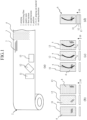
Fig. 1] Fig. 1 shows schematic diagrams showing an example of a prepreg and prepreg cut materials in the present invention and a preform according to the present invention. - [
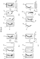
Fig. 2] Fig. 2 shows schematic plan views of prepreg cut materials each illustrating an example of a relationship between a first incision and a second incision provided in a prepreg cut material in the present invention. - [
Fig. 3] Fig. 3 shows schematic plan views of prepreg cut materials each illustrating an example in that a second incision extends along an outline of a prepreg cut material in the present invention. - [
Fig. 4] Fig. 4 shows schematic diagrams each illustrating an example of prepreg cut materials and an example of a preform stacked with them in the present invention. - [
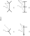
Fig. 5] Fig. 5 shows schematic plan views of second incisions each illustrating an example of a shape of a second incision having a divergent point in the present invention. - [
Fig. 6] Fig. 6 shows schematic plan views of second incisions one of which illustrates an example of a case where a divergent angle of a second incision having a divergent point is 180 degrees or less and the other of which illustrates an example of a case where the divergent angle is more than 180 degrees. - [
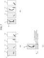
Fig. 7] Fig. 7 is a schematic process diagram showing an example of a timing at which a second incision is provided and an example of stacking into a preform in the present invention. - [
Fig. 8] Fig. 8 shows schematic process diagrams showing another example of a timing at which a second incision is provided and examples of stacking into preforms in the present invention. - [
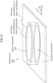
Fig. 9] Fig. 9 is a perspective view of a molded article in Example 1. - [
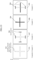
Fig. 10] Fig. 10 shows plan views of prepreg cut materials used in Example 1. - [
Fig. 11] Fig. 11 is a schematic plan view showing a state in which a thick wall portion is formed in Example 1-1. - [
Fig. 12] Fig. 12 is a perspective view of a molded article in Example 2. - [
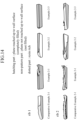
Fig. 13] Fig. 13 shows plan views of prepreg cut materials used in Example 2. - [
Fig. 14] Fig. 14 shows schematic partial perspective views each illustrating a degree of achieving filling intorib - Hereinafter, the present invention will be explained together with embodiments referring to figures.
- The preform according to the present invention is prepared by stacking two or more prepreg cut materials each of which is made by cutting a sheet-like prepreg into an outline of a predetermined shape, the sheet-like prepreg comprising reinforcing fibers aligned in one direction and a matrix resin, and is characterized in that at least one prepreg cut material has first incisions that are regularly distributed throughout the whole in-plane region and a second incision that is provided only in a predetermined specific region and longer than the first incision.
- In the present invention, as the reinforcing fibers used in the prepreg, for example, exemplified are organic fibers such as aramid fibers, polyethylene fibers and polyparaphenylene benzoxadol (PBO) fibers, inorganic fibers such as glass fibers, carbon fibers, silicon carbide fibers, alumina fibers, tyranno fibers, basalt fibers and ceramic fibers, metal fibers such as stainless steel fibers and steel fibers, as others, reinforcing fibers using boron fibers, natural fibers or modified natural fibers or the like as fibers, or the like. Among them, in particular, because carbon fibers are lightweight among these reinforcing fibers, and have particularly excellent properties in specific strength and specific elastic modulus, and are also excellent in heat resistance and chemical resistance, they are suitable for members such as automobile panels for which are desired to be made lightweight. In particular, PAN-based carbon fibers, which make it easy to obtain high-strength carbon fibers, are preferred.
- As the matrix resin used in the prepreg in the present invention, for example, exemplified are a thermosetting resin such as epoxy resin, unsaturated polyester resin, vinyl ester resin, phenol resin, epoxy acrylate resin, urethane acrylate resin, phenoxy resin, alkyd resin, urethane resin, maleimide resin or cyanate resin, and a thermoplastic resin such as polyamide, polyacetal, polyacrylate, polysulfone, ABS, polyester, acrylic, polybutylene terephthalate (PBT), polyethylene terephthalate (PET), polyethylene, polypropylene, polyphenylene sulfide (PPS), polyether ether ketone (PEEK), a liquid crystal polymer, vinyl chloride, a fluoro-based resin such as polytetrafluoroethylene, or silicone. Among them, it is particularly preferable to use a thermosetting resin. Since the prepreg has a tackiness at a room temperature by the condition where the matrix resin is a thermosetting resin, when the prepreg cut materials are stacked, the upper and lower cut materials are integrated by adhesion, and the stacked body can be molded while being maintained with an intended structure.
-
Fig. 1 shows an embodiment of a prepreg and a prepreg cut material in the present invention, and an embodiment of a preform according to the present invention. InFig. 1 (a) ,symbol 1 indicates a sheet-like prepreg comprising reinforcingfibers 2, which are aligned in one direction and extending continuously, and amatrix resin 3. In thisprepreg 1,first incisions 4 which are regularly distributed throughout the whole in-plane region are provided, and the continuous reinforcingfibers 2 are cut by thefirst incisions 4 at the site where thefirst incisions 4 are present. Such regularly distributedfirst incisions 4 can be provided, for example, by the method described in theaforementioned Patent document 3. From thisprepreg 1, for example, a plurality of prepreg cutmaterials prepreg cut materials first incisions 4 distributed regularly throughout the whole in-plane region, as shown inFig. 1 (b) .Symbol 10 indicates a stacking direction of the prepreg cut materials to the preform (the thickness direction of the prepreg cut material or the preform). - In at least one of the above-described
prepreg cut materials prepreg cut materials Fig. 1 (c) , in addition to thefirst incisions 4 regularly distributed throughout the whole in-plane region, a second incision 5 longer than thefirst incision 4, which is curved in a bow shape extending along the outline of each of prepreg cutmaterials prepreg cut materials Fig. 1 (d) to form a preform 6. - In the preform according to the present invention, at least one prepreg cut material among the prepreg cut materials stacked to the preform has the
first incisions 4 which is distributed regularly throughout the whole in-plane region and the second incision 5 that is provided only in the predetermined specific region and longer than thefirst incision 4, but for this second incision 5, various forms (a form including a planar shape of an incision, a depth of an incision, etc.) can be employed depending on the preform to be molded into a fiber-reinforced resin molded article (the product shape of a fiber-reinforced resin molded article to be molded). For example, with respect to the planar shape of the second incision 5, as shown inFig. 2 which exemplifies the relationship between thefirst incisions 4 and the second incision provided in theprepreg cut materials second incision 5a similar to that shown inFig. 1 (Fig. 2 (a) ), a plurality of separatedsecond incisions 5b (Fig. 2 (b) ), the hook-shaped bentsecond incision 5c (Fig. 2 (c) ), and the like. In case where a plurality of second incisions are provided in at least one prepreg cut material, the number of the second incisions is preferably 1/20 or less of the number of the first incisions. - As described above, in the present invention, in at least one prepreg cut material among the prepreg cut materials stacked to the preform, the first incisions distributed regularly throughout the whole in-plane region and the second incision which is provided only in the predetermined specific region and which is longer than the first incision are provided, and the first incisions mainly can contribute to reduce the variation in mechanical properties of at least one prepreg cut material as a whole when molded into a molded article, and to improve the dimensional accuracy of the molded article by improving the followability to a shape of a mold, and the second incision can contribute, especially in case where a fiber-reinforced resin molded article with a product shape having a thickness change is obtained by press molding, to promote smooth flow of both reinforcing fibers and bundles of reinforcing fibers cut by the second incision and the matrix resin existing around them to improve the material yield and production efficiency when making a molded article as a whole of the preform, and to realize a high fill ability into a cavity of a mold to obtain a molded article having further excellent mechanical properties. Further, the presence of the second incision with an appropriate form makes it possible to avoid bridging and tensioning of reinforcing fibers at a corner portion and the like during molding, and to avoid the occurrence of a resin-rich part and warping.
- In case where it is considered that it is effective to provide an appropriate form of second incision, the following various structures can be employed.
- For example, in case where it is considered effective that the second incision extends along the outline of at least one prepreg cut material as a whole, as shown in
Fig. 3 (illustration of the first incisions is omitted), exemplified are asecond incision 5d extending linearly along the side of aprepreg cut material 31 having a rectangular planar shape (Fig. 3 (a) ), a second incision 5e extending curvedly along the arc of aprepreg cut material 32 having an elliptical planar shape (Fig. 3 (b) ), asecond incision 5f extending in an L shape along a part of the outline of aprepreg cut material 33 having a T-shaped planar shape (Fig. 3 (c) ), asecond incision 5g extending in a waveform along a part of the outline of aprepreg cut material 34 having a wavy planar shape (Fig. 3 (d) ) and the like. - Thus, although the second incision can take various shapes and forms, in order that the second incision itself does not become a starting point of a cause of a decrease in strength when the preform is made to a molded article, it is preferred that the second incision does not reach up to the outline of the above-described at least one prepreg cut material.
- Further, although the depth of the second incision is not particularly limited, for one prepreg cut material, it may be either a form extending up to a halfway of the thickness of the prepreg cut material or a form penetrating through the prepreg cut material. In case of the form penetrating through the prepreg cut material, it is preferred that the second incision does not reach up to the outline of the prepreg cut material. Further, as described later, since the second incision can be provided even after a plurality of prepreg cut materials are stacked to make a form of a preform, particularly in that case, it is preferred that the second incision is 50% or more of the thickness of the preform in order to achieve an excellent material yield and a high fill ability of the molding material into a cavity. As the case may be, the second incision may penetrate the preform. In case where the second incision penetrates the preform, it is preferred that the second incision does not reach the outline of the prepreg cut material in the preform.
- Further, the present invention is considered to be effective particularly in case where a product shape having a thickness change or a complicated three-dimensional shape is obtained by press molding, and in that case, at least one prepreg cut material having first incisions and a second incision can be made as a form having a three-dimensional shape portion protruding in the out-of-plane direction, except the planar forms as shown in
Fig. 3 . - Further, in the present invention, with respect to the plurality of prepreg cut materials stacked to the preform, although it is necessary that at least one of the plurality of prepreg cut materials has at least two types of incisions of the first incisions and the second incision, each prepreg cut material to be stacked can take various forms in order to realize an appropriate form as a whole of the preform. For example, the preform according to the present invention may have a form having at least one prepreg cut material selected from the following (A) to (C) in addition to the prepreg cut material having first incisions and second incision.
- (A) a prepreg cut material having only the first incisions
- (B) a prepreg cut material having only the second incision
- (C) a prepreg cut material having no incisions
- To more concretely exemplify the stacking form of the preform, for example, as shown in
Fig. 4 (a) , can be exemplified apreform 51 in which aprepreg cut material 41 havingfirst incisions 4 and asecond incision 5h, aprepreg cut material 42 having only asecond incision 5h, and aprepreg cut material 43 having no incisions, are stacked in a form stacked with theprepreg cut material 41 as an upper layer. - Further, as shown in
Fig. 4 (b) , apreform 52, in which theprepreg cut material 41 having the samefirst incisions 4 andsecond incision 5h as those shown inFig. 4 (a) , aprepreg cut material 44 having only asecond incision 5i with a shape different from that shown inFig. 4 (a) , and aprepreg cut material 45 having only a plurality ofsecond incisions 5j with another shape, are stacked in a form stacked with theprepreg cut material 41 as an upper layer, can be exemplified. - Further, as shown in
Fig. 4 (c) , apreform 53, in which aprepreg cut material 46 havingfirst incisions 4 and asecond incision 5k, aprepreg cut material 47 having onlyfirst incisions 4, and aprepreg cut material 43 having no incisions, are stacked in a form stacked with theprepreg cut material 46 as an upper layer, can be exemplified. - Furthermore, as shown in
Fig. 4 (d) , apreform 54, in which aprepreg cut material 48 having only asecond incision 51, aprepreg cut material 49 having thefirst incisions 4 and asecond incision 5m, and aprepreg cut material 50 having only asecond incision 5n, are stacked in a form stacked with theprepreg cut material 48 as an upper layer, can be exemplified. - Further, in the present invention, the second incision can have at least one divergent point. This makes it possible to make the second incision more appropriately follow the outline of the prepreg cut material and to make the second incision exist in a more appropriate region, and a greater effect can be expected by providing the second incision.
- As the shape of the whole second incision in case where the second incision has at least one divergent point, for example, as shown in
Fig. 5 as an example of the planar shape of the second incision, can be exemplified a second incision So diverged radially in three directions at a divergent point 61 (Fig. 5 (a) ), asecond incision 5p diverged in two directions at eachbranch point 62 at each end (Fig. 5 (b) ), a second incision 5q diverged at respectivedivergent points 63 so that incisions having different lengths intersect in orthogonal directions (Fig. 5 (c) ), asecond incision 5r diverged at respectivedivergent points 64 so that incisions having the same length intersect in orthogonal directions (Fig. 5 (d) ), and the like. - In case where the second incision has at least one divergent point as described above, it is preferred that any of divergent angles at each divergent point is 180 degrees or less. For example, in a
second incision 5s exemplified inFig. 6 (a) , any of divergent angles at eachdivergent point second incision 5t exemplified inFig. 6 (b) , because one divergent angle at each ofdivergent points 67, 68 exceeds 180 degrees, it is an unfavorable embodiment. By opening a larger area with an incision of a short incision length, it is possible to obtain a good deformability while exhibiting good mechanical properties. Namely, in case where the divergent angle is 180 degrees or less, the triangular region surrounded by the two incisions forming this divergent angle can be deformed in the out-of-plane direction. On the other hand, in case where the divergent angle exceeds 180 degrees, because the similar region cannot be deformed out of the plane, the area that can be opened via the second incision decreases. - The present invention is suitable for a preform used for molding a molded article having a thin wall portion and a thick wall portion, and is also effective for a case where the second incision is arranged at a position of the preform corresponding to the thick wall portion of the molded article, and for example, it is possible to eliminate stretching of fibers at the end of a thick wall portion such as a rib.
- In the present invention, in a preform used for molding a molded article having a thin wall portion and a thick wall portion, by providing the second incision in a region of the preform corresponding to the thin wall portion of the molded article, it is possible to eliminate the stretching of fibers occurring in the thin wall portion. Further, in case where a large thickness change of a preform is required in the thin wall portion, it was not possible to obtain a desired thickness in the conventional technology because the preform cannot be pushed sufficiently, but by providing the second incision in the thin wall portion, the second incision is opened, and because the excess material flows to the thick wall portion, a molded article having a desired thickness can be obtained. When the second incision is provided in the thin wall portion surrounded by the thick wall portion, the length of the second incision is preferably 1/2 or more of the length of the outer circumference of the thin wall portion.
- Further, in the present invention, the second incision can be provided at least in a region of the preform corresponding to a boundary between the thin wall portion and the thick wall portion of the molded article. By having the second incision in the region of the preform corresponding to the boundary between the thin wall portion and the thick wall portion of the molded article, occurrence of the region having a high fiber volume content (high Vf) generated on the thin wall portion side of the boundary between the thin wall portion and the thick wall portion can be avoided. Namely, when the material is pulled into the thick wall portion, there may be a case where the fibers are stretched at the boundary portion due to the difference in peripheral length between the portion having the thick wall portion and the portion other than the thick wall portion, and the high Vf region is created by the fibers collected from the surroundings due to the pulling. By this, there is a possibility that the mold cannot be completely closed to a desired thickness, or that cracks occur in the high Vf portion. By providing the second incision in this region, the stretching of the fibers is eliminated, the collected fibers are easily drawn into the thick wall portion, the region of high Vf is eliminated, and the mold can be closed to the desired thickness.
- Further, in case where the stacked body is filled into the thick wall portion, usually, the stacked body is filled so as to be bent in the out-of-plane direction with elongation of the material and slipping between layers. However, if both ends of the thick wall portion are restrained, the deformation of the stacked body in the out-of-plane direction is suppressed. In particular, in case where both ends of the thick wall portion are thin wall portions, this restraint is likely to occur. By having the second incision in the region of the preform corresponding to the thick wall portion of the molded article, because the incision becomes the flow end, the material can be filled in the thick wall portion without accompanying with deformation in the out-of-plane direction.
- In addition, since the material is filled in the thick wall portion part through the incision becoming the flow end, by providing the second incision along the thick wall portion, the distance from the incision to the end of the thick wall portion (product surface) is reduced, and the filling becomes easy.
- Further, in the present invention, it is preferred that the length L2 of the second incision satisfies the following equation (a).

- Namely, when the stretching of fibers is eliminated and the material is pulled into the thick wall portion, the fibers corresponding to the surface area of the thick wall portion are pulled. When the surface of the thick wall portion is developed in a plane, since the length in the direction orthogonal to the longitudinal direction is (2t + the width of the thick wall portion), from the viewpoint preventing the fibers contained in at least a zone of 2t or more from stretching, the length of the above-described equation (a) is required. The fiber stretching is greatly affected by the fiber direction of the surface layer.
- Further, in the present invention, in case where the second incision extends along the extending direction of the thick wall portion, it is also preferred that the length L2 of the second incision is equal to a length in a principal axis direction of the thick wall portion or more. Since the thick wall portion is filled through the incision becoming the flow end, the longer the length of the second incision is, the larger the flow end becomes, and by making the length of the second incision equal to the length of the thick wall portion or more, the flow end is formed over the entire region directly below the thick wall portion, and the filling is improved.
- Furthermore, the influence of the fibers on the surface layer is large on the stretching of fibers, and the effect of cutting the fibers is great for eliminating or reducing the stretching of fibers. Therefore, in the present invention, in order to efficiently cut the fibers with a shorter incision, it is also preferred that the angle formed between the second incision and a fiber direction of a surface layer of the preform forming the thick wall portion is in a range of 90 degrees ± 15 degrees.
- As a method for producing a preform according to the present invention, any of the following methods can be employed. (I) a method comprising the following steps of: (a) a step of forming a plurality of prepreg cut materials each of which is made by cutting a sheet-like prepreg into an outline of a predetermined shape, the sheet-like prepreg comprising reinforcing fibers aligned in one direction and a matrix resin, (b) a step of stacking the plurality of prepreg cut materials in a form of a preform, and (c) a step of providing, to at least one prepreg cut material among the plurality of prepreg cut materials, in addition to first incisions that have been regularly provided throughout the whole in-plane region, a second incision that is longer than the first incision only in a predetermined specific region, wherein the step (c) is carried out between the step (a) and the step (b) or before the step (a), or (II) a method comprising the following steps of: (a) a step of forming a plurality of prepreg cut materials each of which is made by cutting a sheet-like prepreg into an outline of a predetermined shape, the sheet-like prepreg comprising reinforcing fibers aligned in one direction and a matrix resin, (b) a step of stacking the plurality of prepreg cut materials in a form of a preform, and (c) a step of providing, to at least one prepreg cut material among the plurality of prepreg cut materials, in addition to first incisions that have been regularly provided throughout the whole in-plane region, a second incision that is longer than the first incision only in a predetermined specific region, wherein the step (c) is carried out after the step (b). Namely, a targeted second incision may be provided before stacking a plurality of prepreg cut materials in a form of a preform or may be provided after the stacking.
- In these methods for producing the preform, similarly to the aforementioned forms of the preform of the present invention, a preform to be produced can comprise, in addition to the prepreg cut material having the first incisions and the second incision, at least one prepreg cut material selected from the following (A) to (C).
- (A) a prepreg cut material having only the first incisions
- (B) a prepreg cut material having only the second incision
- (C) a prepreg cut material having no incisions
- The above-described production methods (I) and (II) will be exemplified.
- For example, as exemplified in
Fig. 7 with respect to the production method (I), aprepreg cut material 71 havingfirst incisions 4, aprepreg cut material 72 havingfirst incisions 4 in a different direction, aprepreg cut material 73 having no incisions, and aprepreg cut material 74 having reinforcingfibers 2 in a different direction and having no incisions, are made (Fig. 7 (a) ), theprepreg cut material 71 is provided with asecond incision 5u and theprepreg cut material 73 is provided with asecond incision 5v having substantially the same shape (Fig. 7 (b) ), and by stacking theseprepreg cut material 71 having two kinds of the first and second incisions,prepreg cut material 72 having only the first incisions,prepreg cut material 73 having only the second incision, andprepreg cut material 74 having no incisions, apreform 81 can be configured (Fig. 7 (c) ). - Further, as exemplified in
Fig. 8 with respect to the production method (II), a prepreg cut material 71 having first incisions 4, a prepreg cut material 72 having first incisions 4 in a different direction, a prepreg cut material 73 having no incisions, and a prepreg cut material 74 having reinforcing fibers 2 in a different direction and having no incisions, are made (Fig. 8 (a) ), a second incision 5w is provided in the prepreg cut material 71 as needed (Fig. 8 (b) ) (in this case, there is a possibility that the second incision 5w is not provided and the step ofFig. 8 (b) is omitted.), and by stacking these prepreg cut material 71 having two kinds of the first and second incisions, prepreg cut material 72 having only the first incisions, prepreg cut material 73 having no incisions, and prepreg cut material 74 having no incisions, a preform 82 as a precursor of a finally targeted preform is made (Fig. 8 (c) ), and with respect to the preform 82 as a precursor, a second incision 5x is cut and inserted following the second incision 5w of one prepreg cut material 71 which appears on the surface so as to penetrate the preform over the entire thickness direction of the preform, to configure a finally targeted preform 83 (Fig. 8 (d) ). This finally formedpreform 83 has a stacking structure of aprepreg cut material 71 having two kinds of the first and second incisions, aprepreg cut material 72 having two kinds of the first and second incisions, aprepreg cut material 73 having only the second incision, and aprepreg cut material 74 having only the second incision. - Thus, with respect to the second incision to be finally formed, the shape, depth, etc., as well as the timing of providing can be freely set in accordance with the form of the finally molded article, etc.
- Hereinafter, examples of the preform according to the present invention, in particular, examples of the preform used for molding a molded article having a thin wall portion and a thick wall portion, will be explained with reference to the drawings.
- A molded
article 101 having a shape shown inFig. 9 was press-molded using a double-sided mold having a cavity in the shape of a molded article. In the moldedarticle 101, a cylindricalthick wall portion 103 is integrally molded on a flat plate-shapedthin wall portion 102.Symbol 104 indicates the inner circumference of the thick wall portion, andsymbol 105 indicates the outer circumference of the thick wall portion.Numerals Fig. 9 represent the orientation angle directions (unit: degree) of the reinforcing fibers in the prepregs stacked in the preform preparation stage. With respect to the moldedarticle 101 having such a shape,Fig. 10 shows the planar shapes of the prepreg cut materials for forming the preform region corresponding to thethick wall portion 103 of the moldedarticle 101 and the shapes when the second incisions are provided. Aprepreg cut material 106 in Example 1-1, aprepreg cut material 107 in Example 1-2, aprepreg cut material 108 in Comparative Example 1-1 and aprepreg cut material 109 in Comparative Example 1-2 were used, respectively, and a predetermined number of the respective prepreg cut materials were stacked to form a region of a preform before press molding corresponding to the wallthick portion 103. - The prepreg used was "TORAYCA" (registered trademark) prepreg sheet P3252S-20 (yarn areal weight: 200 gsm, resin content: 33%, prepreg areal weight: 299 gsm, thickness: 0.19 mm), and the carbon fiber of the prepreg was T700SC (density: 1.80, tensile strength :500 kgf / mm2, tensile elastic modulus: 23.5 tf / mm2) and the resin was #2592 (epoxy, 130°C curing type). Further, first incisions were inserted over the whole region of this prepreg, and it was used as an incision prepreg in Examples 1-1 and 1-2 and Comparative Example 1-1. In Comparative Example 1-2, a prepreg in which the first incisions were not inserted was used.
- The ply number of the preform of the thick wall portion, that is, the number of stacked layers (for example, 16 ply) was set to a value obtained by dividing the volume of the thick wall portion by the area of the prepreg cut material and the thickness of one prepreg.
- The material yield is a value obtained by dividing the total area of the prepreg cut materials used for the preform by the area of the prepreg sheet before cutting out the prepreg cut materials.
- The resin rich or resin-rich part is a region of only resin having a fiber volume content Vf smaller than that of a healthy part or containing no fibers. If there is a resin rich, the color of the resin causes yellowing or whitening which deteriorates the appearance, and the mechanical properties also reduce. In addition to those generated on the surface of the molded article, those confirmed by cross-sectional observation were also added to the evaluation.
- Further, the
thin wall portion 102 in the central portion of the moldedarticle 101 shown inFig. 9 was detected in flaw using an ultrasonic flaw detector, and the height of the bottom echo was measured. The measurement points were three points of the center of the thin wall portion, the middle point between the center of the thin wall portion and the right end of the thin wall portion and the middle point between the center of the thin wall portion and the left end of the thin wall portion, and an average value of these was shown in Table 1. If there are "flaws" such as voids and peelings inside the molded article, the value of the height of bottom echo becomes small. Further, the height of bottom echo becomes 0 when a large "flaw" is present. Where, it was adjusted so that the height of bottom echo of a molded article with the same thickness as the thin wall portion having no "flaw" became 100%, and the height of bottom echo of 80% or more was determined to be acceptable. - The molded
article 101 was cut at the center in the direction of 90 degrees, and the cross section was observed after resin filling and polishing to evaluate the presence or absence of voids. - The length of the second incision of the
prepreg cut material 106 shown inFig. 10 was set so as to become 1/2 of the length of the inner circumference of the thick wall portion of the molded article. The prepreg cut material inserted with the second incision was cut using an automatic cutting machine, and 16 plies of [(0/90)s/(45/-45)s]s were stacked to prepare a preform of a thick wall portion (the above-described numerical values represent the orientation direction of the reinforcing fibers with respect to the fiber orientation directions shown inFig. 9 .). The second incision of the preform of the thick wall portion penetrated in the preform thickness direction. Subsequently, 8 plies of [0/90/45/-45]s were stacked to prepare a preform of a thin wall portion. No second incision was inserted in the thin wall portion. Furthermore, the preform of the thick wall portion and the preform of the thin wall portion were overlapped and integrated. The material yield of the preform of the thick wall portion was 43%. Then, the integrated preform was press molded using a double-sided mold having a cavity with a molded article shape. The obtained molded article had no resin richness or voids, and the value of the height of bottom echo was also good. - The end of the second incision was set so as to reach the boundary between the thin wall portion and thick wall portion. An integrated preform was prepared in the same manner as in Example 1, and press molded in the same manner as in Example 1. The obtained molded article was as good as in Example 1.
- In the above-described Examples, as shown in
Fig. 11 as an example of how the thick wall portion in Example 1-2 was formed, first the second incision was opened to suppress the stretching of the fibers, and further, by the condition where the material followed up to the end of the molded article shape by the first incisions, a molded article having a good quality was obtained. - An integrated preform was prepared in the same manner as in Example 1-1 other than a condition where the second incision was not inserted. Although resin richness did not occur on the surface of the molded article, resin richness was confirmed inside the thick wall portion as the result of cross-sectional observation. Further, a plurality of voids with a size of several hundred µm were confirmed by cross-sectional observation, and the value of the height of bottom echo in the ultrasonic flaw detection was also small, and an inferior internal quality was resulted.
- A prepreg having no first incisions was used. A prepreg cut material having a cylindrical shape that matches the cross-sectional shape of the thick wall portion was cut by an automatic cutting machine, and 24plies of [(0/90)s/(45/-45)s/(0/90)s]s were stacked to prepare a preform of a thick wall portion. Further, a preform of the thin wall portion was prepared in the same manner as in Example 1-1, integrated with the preform of the thick wall portion, and the integrated preform was press molded using a double-sided mold with a cavity having the shape of a molded article. Although the quality of the obtained molded article was good, the material yield of the preform of the thick wall portion was reduced to 36% by the occurrence of loss due to the hollowing out of the center part. Furthermore, since the number of stacked sheets increased by 1.5 times, it took time for the stacking work.
- Table 1 summarizes the results of evaluating the moldability of the preform using each prepreg cut material shown in
Fig. 10 .[Table 1] First incision Second incision Number of stacked pieces Material yield (thick wall portion) Resin rich Height of bottom echo Voids Example 1-1 present present 16 43% none 98% none Example 1-2 present present 16 43% none 100% none Comparative Example 1-1 present none 16 43% present 54% present Comparative Example 1-2 none none 24 36% none 100% none - A molded
article 201 having a shape shown inFig. 12 was press molded using a double-sided mold with a cavity having a shape of the molded article. In the moldedarticle 201, a rib 1 (203) and a rib 2 (204) intersecting in a cross shape as a thick wall portion are integrally molded on a flat plate-shapedthin wall portion 202.Symbols Fig. 12 represent the orientation angle directions (unit: degree) of the reinforcing fibers in the prepregs stacked in the preform preparation stage.Symbol 205 indicates the boundary between the thick wall portion and the thin wall portion, andsymbol 206 indicates a second incision. With respect to the moldedarticle 201 having such a shape,Fig, 13 shows planar shapes of prepreg cut materials having preform regions corresponding to the thick wall portions (portions ofribs 203 and 204) in addition to thethin wall portion 202 of the moldedarticle 201 and the shapes of second incisions in case where the second incisions are provided. Using aprepreg cut material 207 in Example 2-1, aprepreg cut material 208 in Example 2-2, aprepreg cut material 209 in Example 2-3 and aprepreg cut material 210 in Comparative Example 2-1, respectively, a predetermined number of the respective prepreg cut materials were stacked and press molded using a double-sided mold with a cavity having the shape of a molded article, to mold a molded article having the shape as shown inFig. 12 . Where, as to Example 2, both the Comparative Example and the Example used an incision prepreg having the first incisions. Further, the longitudinal direction of therib 1 is the 0 degree direction, and the longitudinal direction of therib 2 is the 90 degree direction. Table 2 summarizes the results of evaluating the moldability of the preform using each prepreg cut material shown inFig. 13 . - The same prepreg as in Example 1 was used as the material. The reachable height of the rib is the (partially) maximum reachable height in each rib when the height of the rib fully filled is referred to as 100%. It becomes 0% when it is not filled at all. It was measured using a ruler.
- The filling rate of the rib is a filling amount in each rib when the volume of the rib fully filled is referred to as 100%. It becomes 0% when it is not filled at all. The size of the unfilled portion was measured using a ruler to calculate the volume of the unfilled portion, and the filling rate was calculated by subtracting the volume of the unfilled portion from the volume of the rib fully filled.
- Resin richness was determined by appearance inspection, and the existing one was determined as Y and the non-existing one was determined as N.
- A preform was prepared by stacking 6 plies of [0/90/0]s prepreg cut materials each having no second incisions. Then, it was press molded using a double-sided mold with a cavity having a shape of a molded article. The maximum reachable height was 70%, the filling rate was 50% or less, and resin richness also occurred.
- After preparing a preform similar to that in Comparative Example 2-1, a second incision was inserted using a cutter knife so that it penetrated the preform at a position just below the boundary between the thick wall portion and the thin wall portion. In the
rib 1, the filling height reached 100%, the filling rate was improved by 45 points, and resin richness did not occur. On the other hand, therib 2 showed only a slight improvement in the filling rate. - It is that the stretching of fibers occurred at the boundary between thick wall portion and the thin wall portion was alleviated, and this is effect is highly effective on the rib extending in the 0 degree direction. If the fibers are stretched, a region of high Vf is generated at that location and the mold cannot be pushed completely, and therefore, the molded article cannot have a desired thickness. If the mold can be pushed completely, the thin wall portion has a desired thickness, and the change in thickness at that time fills the thick wall portion to uniformly achieve a targeted Vf.
- After preparing a preform similar to that in Comparative Example 2-1, a second incision was inserted using a cutter knife so that it penetrated the preform at a position just below the thick wall portion. The filling heights at
ribs - It is that the flow end was formed just below the rib, and this is highly effective on the rib extending in the 90 degree direction. When the rib is filled with the stacked body, it is necessary to fill the rib accompanying with deformation in that the stacked body bends in the out-of-plane direction, but in case where the second incision is present directly below the thick wall portion, it becomes possible that the rib is filled only by the in-plane flow.
- A prepreg cut material having a second incision was cut using an automatic cutting machine and 6 plies of [0/90/0]s were stacked to prepare a preform. The second incision penetrated through the preform in the thickness direction of the preform. The
rib 1 was completely filled and resin richness also did not occur. Therib 2 also showed an improvement similarly to in Example 2-2. - Where,
Fig. 14 shows the results of visually observing the degree of achievement of filling to theribs [Table 2] Rib 1Rib 2Reachable height Filling rate Resin rich Reachable height Filling rate Resin rich Comparative Example 2-1 70% 50% Y 60% 30% Y Example 2-1 100% 95% N 60% 60% Y Example 2-2 100% 90% N 100% 80% N Example 2-3 100% 100% N 100% 75% N - The preform and the method for producing the same according to the present invention can be applied to the production of any fiber-reinforced resin molded article, and are particularly suitable for the production of molded articles having a thickness change or a complicated three-dimensional shape.
-
- 1: prepreg
- 2: reinforcing fiber
- 3: matrix resin
- 4: first incision
- 5, 5a, 5b, 5c, 5d, 5e, 5f, 5g, 5h, 5i, 5j, 5k, 51, 5m, 5n, So, 5p, 5q, 5r, 5s, 5t, 5u, 5v, 5w, 5x: second incision
- 6, 51, 52, 53, 54, 81, 83: preform
- 10: stacking direction
- 11, 12, 13, 21, 22, 23, 31, 32, 33, 34, 41, 42, 43, 44, 45, 46, 47, 48, 49, 50, 71, 72, 73, 74: prepreg cut material
- 61, 62, 63, 64, 65, 66, 67: divergent point
- 82: precursor of preform
- 101, 201: molded article
- 102, 202: thin wall portion
- 103: thick wall portion
- 104: inner circumference of thick wall portion
- 105: outer circumference of thick wall portion
- 106, 107, 108, 109, 207, 208, 209, 210: prepreg cut material
- 203:
rib 1 - 204:
rib 2 - 205: boundary between thick wall portion and thin wall portion
- 206: second incision
Claims (21)
- A preform prepared by stacking two or more prepreg cut materials each of which is made by cutting a sheet-like prepreg into an outline of a predetermined shape, the sheet-like prepreg comprising reinforcing fibers aligned in one direction and a matrix resin, characterized in that at least one prepreg cut material has first incisions that are regularly distributed throughout the whole in-plane region and a second incision that is provided only in a predetermined specific region and longer than the first incision.
- The preform according to claim 1, wherein the number of the second incisions in said at least one prepreg cut material is 1/20 or less of the number of the first incisions.
- The preform according to claim 1 or 2, wherein the second incision extends, as a whole, along the outline of said at least one prepreg cut material.
- The preform according to any of claims 1 to 3, wherein the preform comprises a preform a prepreg cut material having the first incisions and the second incision and at least one prepreg cut material selected from the following (A) to (C).(A) prepreg cut material having only the first incisions(B) prepreg cut material having only the second incision(C) prepreg cut material having no incisions
- The preform according to any of claims 1 to 4, wherein the second incision does not reach up to the outline of said at least one prepreg cut material.
- The preform according to any of claims 1 to 5, wherein a plurality of prepreg cut materials each having the second incision are provided, and the total depth of the second incisions of the plurality of prepreg cut materials is 50% or more of the thickness of the preform.
- The preform according to any of claims 1 to 6, wherein the second incision penetrates through the preform.
- The preform according to any of claims 1 to 7, wherein the second incision has at least one divergent point.
- The preform according to claim 8, wherein any of divergent angles at the divergent point of the second incision is 180 degrees or less.
- The preform according to any of claims 1 to 9, wherein said at least one prepreg cut material has a three-dimensional shape portion protruding in an out-of-plane direction.
- The preform according to any of claims 1 to 10, wherein the preform is a preform used for molding a molded article having a thin wall portion and a thick wall portion.
- The preform according to claim 11, wherein the second incision is provided at least in a region of the preform corresponding to the thin wall portion of the molded article.
- The preform according to claim 11 or 12, wherein the second incision is provided at least in a region of the preform corresponding to a boundary between the thin wall portion and the thick wall portion of the molded article.
- The preform according to any of claims 11 to 13, wherein the second incision is provided at least in a region of the preform corresponding to the thick wall portion of the molded article.
- The preform according to any of claims 11 to 14, wherein the second incision extends along a direction in which the thick wall portion extends.
- The preform according to any of claims 11 to 15, wherein a length L2 of the second incision satisfies the following equation (a).

- The preform according to claim 15, wherein a length L2 of the second incision is equal to a length in a principal axis direction of the thick wall portion or more.
- The preform according to any of claims 11 to 17, wherein an angle formed between the second incision and a fiber direction of a surface layer of the preform forming the thick wall portion is in a range of 90 degrees ± 15 degrees.
- A method for producing a preform comprising the following steps of:(a) a step of forming a plurality of prepreg cut materials each of which is made by cutting a sheet-like prepreg into an outline of a predetermined shape, the sheet-like prepreg comprising reinforcing fibers aligned in one direction and a matrix resin,(b) a step of stacking the plurality of prepreg cut materials in a form of a preform, and(c) a step of providing, to at least one prepreg cut material among the plurality of prepreg cut materials, in addition to first incisions that have been regularly provided throughout the whole in-plane region, a second incision that is longer than the first incision only in a predetermined specific region,
wherein the step (c) is carried out between the step (a) and the step (b) or before the step (a). - A method for producing a preform comprising the following steps of:(a) a step of forming a plurality of prepreg cut materials each of which is made by cutting a sheet-like prepreg into an outline of a predetermined shape, the sheet-like prepreg comprising reinforcing fibers aligned in one direction and a matrix resin,(b) a step of stacking the plurality of prepreg cut materials in a form of a preform, and(c) a step of providing, to at least one prepreg cut material among the plurality of prepreg cut materials, in addition to first incisions that have been regularly provided throughout the whole in-plane region, a second incision that is longer than the first incision only in a predetermined specific region,
wherein the step (c) is carried out after the step (b). - The method for producing a preform according to claim 19 or 20, wherein a preform to be produced comprises, in addition to the prepreg cut material having the first incisions and the second incision, at least one prepreg cut material selected from the following (A) to (C).(A) a prepreg cut material having only the first incisions(B) a prepreg cut material having only the second incision(C) a prepreg cut material having no incisions
Applications Claiming Priority (2)
| Application Number | Priority Date | Filing Date | Title |
|---|---|---|---|
| JP2020052611 | 2020-03-24 | ||
| PCT/JP2020/047904 WO2021192464A1 (en) | 2020-03-24 | 2020-12-22 | Preform and method for producing same |
Publications (2)
| Publication Number | Publication Date |
|---|---|
| EP4129601A1 true EP4129601A1 (en) | 2023-02-08 |
| EP4129601A4 EP4129601A4 (en) | 2024-04-17 |
Family
ID=77891239
Family Applications (1)
| Application Number | Title | Priority Date | Filing Date |
|---|---|---|---|
| EP20926445.6A Pending EP4129601A4 (en) | 2020-03-24 | 2020-12-22 | Preform and method for producing same |
Country Status (5)
| Country | Link |
|---|---|
| US (1) | US20230113270A1 (en) |
| EP (1) | EP4129601A4 (en) |
| JP (1) | JPWO2021192464A1 (en) |
| TW (1) | TW202204496A (en) |
| WO (1) | WO2021192464A1 (en) |
Family Cites Families (13)
| Publication number | Priority date | Publication date | Assignee | Title |
|---|---|---|---|---|
| US8361265B2 (en) * | 2006-09-28 | 2013-01-29 | Toray Industries, Inc. | Process for producing composite prepreg base, layered base, and fiber-reinforced plastic |
| JP5272418B2 (en) | 2007-02-02 | 2013-08-28 | 東レ株式会社 | Cut prepreg base material, composite cut prepreg base material, laminated base material, fiber reinforced plastic, and method for producing cut prepreg base material |
| CN101600550B (en) * | 2007-02-02 | 2013-03-20 | 东丽株式会社 | Prepreg base material, layered base material, fiber-reinforced plastic, process for producing prepreg base material, and process for producing fiber-reinforced plastic |
| JP2008260793A (en) * | 2007-04-10 | 2008-10-30 | Toray Ind Inc | Laminated substrate and fiber-reinforced plastic |
| JP2009292002A (en) * | 2008-06-04 | 2009-12-17 | Toray Ind Inc | Method of manufacturing fiber-reinforced plastics |
| JP5292972B2 (en) * | 2008-07-30 | 2013-09-18 | 東レ株式会社 | Manufacturing method of fiber reinforced plastic |
| US8052826B2 (en) * | 2009-03-24 | 2011-11-08 | The Boeing Company | Method of making bead-stiffened composite parts and parts made thereby |
| JP5950149B2 (en) | 2011-09-29 | 2016-07-13 | 三菱レイヨン株式会社 | A method for producing a fiber-reinforced resin structure. |
| JP2014172267A (en) * | 2013-03-08 | 2014-09-22 | Mitsubishi Rayon Co Ltd | Laminate substrate |
| JP6459475B2 (en) | 2013-12-25 | 2019-01-30 | 三菱ケミカル株式会社 | Prepreg and method for producing molded product |
| PT3196238T (en) * | 2014-09-19 | 2019-08-06 | Toray Industries | Notched pre-preg and notched pre-preg sheet |
| EP3431272B1 (en) * | 2016-03-16 | 2021-02-17 | Toray Industries, Inc. | Manufacturing method for fiber-reinforced plastic |
| WO2018142962A1 (en) * | 2017-02-02 | 2018-08-09 | 東レ株式会社 | Method for producing fiber-reinforced plastic |
-
2020
- 2020-12-22 WO PCT/JP2020/047904 patent/WO2021192464A1/en unknown
- 2020-12-22 JP JP2020571896A patent/JPWO2021192464A1/ja active Pending
- 2020-12-22 US US17/911,877 patent/US20230113270A1/en active Pending
- 2020-12-22 EP EP20926445.6A patent/EP4129601A4/en active Pending
-
2021
- 2021-03-18 TW TW110109693A patent/TW202204496A/en unknown
Also Published As
| Publication number | Publication date |
|---|---|
| EP4129601A4 (en) | 2024-04-17 |
| TW202204496A (en) | 2022-02-01 |
| JPWO2021192464A1 (en) | 2021-09-30 |
| WO2021192464A1 (en) | 2021-09-30 |
| US20230113270A1 (en) | 2023-04-13 |
Similar Documents
| Publication | Publication Date | Title |
|---|---|---|
| EP2974842B1 (en) | Layered substrate and method for manufacturing same | |
| JP6962191B2 (en) | Manufacturing method of fiber reinforced plastic and fiber reinforced plastic | |
| EP2127840B1 (en) | Prepreg base material,laminated base material, process for producing prepreg base material, and process for producing fiberreinforced plastic | |
| EP1473130B1 (en) | Fiber-reinforced composite material and method for production thereof | |
| US9884954B2 (en) | Random mat and fiber-reinforced composite material shaped product | |
| JP6947034B2 (en) | Notch prepreg and method of manufacturing notch prepreg | |
| CN102395458A (en) | Method for manufacturing composite material member and laminated body of prepreg sheet | |
| JP2019039124A (en) | Chopped fiber bundle mat | |
| EP3950283A1 (en) | Fiber-reinforced resin molding material molded product and method for producing same | |
| Öteyaka et al. | Effect of infill ratio on the tensile and flexural properties of unreinforced and carbon fiber-reinforced polylactic acid manufactured by fused deposition modeling | |
| EP4129601A1 (en) | Preform and method for producing same | |
| EP2784197B1 (en) | Carbon fiber base material and carbon fiber reinforced plastic | |
| TW201919839A (en) | Fiber reinforced plastic and fiber reinforced plastic manufacturing method | |
| EP3578332B1 (en) | Method for producing fiber-reinforced plastic | |
| EP3578331A1 (en) | Method for producing fiber-reinforced plastic | |
| WO2020041104A1 (en) | Hybrid reinforcement fabric | |
| EP4316792A1 (en) | Flat, lightweight member and manufacturing method therefor | |
| EP3348372A1 (en) | Molded article having hole, and method for producing same | |
| EP3841237A1 (en) | Hybrid reinforcement fabric | |
| Iwahori et al. | Experimental investigation of interlaminar mechanical properties on carbon fiber stitched CFRP laminates | |
| EP4316793A1 (en) | Flat lightweight member and method for producing same | |
| JP2018075727A (en) | Continuous fiber reinforcement | |
| JP2023097543A (en) | Preform with overlapping portion and molded body | |
| KR101434730B1 (en) | Method of manufacturing window frame, and window frame manufactured thereby | |
| Byun et al. | Architectural effect on mechanical properties of 3D carbon/PPS composites |
Legal Events
| Date | Code | Title | Description |
|---|---|---|---|
| STAA | Information on the status of an ep patent application or granted ep patent |
Free format text: STATUS: THE INTERNATIONAL PUBLICATION HAS BEEN MADE |
|
| PUAI | Public reference made under article 153(3) epc to a published international application that has entered the european phase |
Free format text: ORIGINAL CODE: 0009012 |
|
| STAA | Information on the status of an ep patent application or granted ep patent |
Free format text: STATUS: REQUEST FOR EXAMINATION WAS MADE |
|
| 17P | Request for examination filed |
Effective date: 20220906 |
|
| AK | Designated contracting states |
Kind code of ref document: A1 Designated state(s): AL AT BE BG CH CY CZ DE DK EE ES FI FR GB GR HR HU IE IS IT LI LT LU LV MC MK MT NL NO PL PT RO RS SE SI SK SM TR |
|
| DAV | Request for validation of the european patent (deleted) | ||
| DAX | Request for extension of the european patent (deleted) | ||
| A4 | Supplementary search report drawn up and despatched |
Effective date: 20240318 |
|
| RIC1 | Information provided on ipc code assigned before grant |
Ipc: B29K 105/10 20060101ALI20240312BHEP Ipc: B29B 11/16 20060101AFI20240312BHEP |