EP3348372A1 - Molded article having hole, and method for producing same - Google Patents
Molded article having hole, and method for producing same Download PDFInfo
- Publication number
- EP3348372A1 EP3348372A1 EP16844051.9A EP16844051A EP3348372A1 EP 3348372 A1 EP3348372 A1 EP 3348372A1 EP 16844051 A EP16844051 A EP 16844051A EP 3348372 A1 EP3348372 A1 EP 3348372A1
- Authority
- EP
- European Patent Office
- Prior art keywords
- hole
- molded article
- region
- carbon fibers
- molding material
- Prior art date
- Legal status (The legal status is an assumption and is not a legal conclusion. Google has not performed a legal analysis and makes no representation as to the accuracy of the status listed.)
- Granted
Links
- 238000004519 manufacturing process Methods 0.000 title claims description 55
- 229920000049 Carbon (fiber) Polymers 0.000 claims abstract description 220
- 239000004917 carbon fiber Substances 0.000 claims abstract description 220
- VNWKTOKETHGBQD-UHFFFAOYSA-N methane Chemical compound C VNWKTOKETHGBQD-UHFFFAOYSA-N 0.000 claims abstract description 41
- 229920005992 thermoplastic resin Polymers 0.000 claims abstract description 40
- 239000012778 molding material Substances 0.000 claims description 169
- 239000000835 fiber Substances 0.000 claims description 150
- 238000000034 method Methods 0.000 claims description 20
- 238000003825 pressing Methods 0.000 claims description 17
- 239000000203 mixture Substances 0.000 claims description 7
- 229920005989 resin Polymers 0.000 description 75
- 239000011347 resin Substances 0.000 description 75
- 238000000465 moulding Methods 0.000 description 38
- 229920002292 Nylon 6 Polymers 0.000 description 20
- -1 polypropylene Polymers 0.000 description 17
- 239000010410 layer Substances 0.000 description 14
- 238000005520 cutting process Methods 0.000 description 13
- 239000002243 precursor Substances 0.000 description 12
- 238000012360 testing method Methods 0.000 description 12
- 230000002093 peripheral effect Effects 0.000 description 10
- 230000000052 comparative effect Effects 0.000 description 9
- 230000007423 decrease Effects 0.000 description 9
- 238000011156 evaluation Methods 0.000 description 9
- 238000005259 measurement Methods 0.000 description 8
- 238000002844 melting Methods 0.000 description 7
- 230000008018 melting Effects 0.000 description 7
- PPBRXRYQALVLMV-UHFFFAOYSA-N Styrene Chemical compound C=CC1=CC=CC=C1 PPBRXRYQALVLMV-UHFFFAOYSA-N 0.000 description 6
- 229920002239 polyacrylonitrile Polymers 0.000 description 6
- 230000006835 compression Effects 0.000 description 5
- 238000007906 compression Methods 0.000 description 5
- 238000010438 heat treatment Methods 0.000 description 5
- 230000008859 change Effects 0.000 description 4
- 238000000354 decomposition reaction Methods 0.000 description 4
- 230000000694 effects Effects 0.000 description 4
- 230000009477 glass transition Effects 0.000 description 4
- 239000000523 sample Substances 0.000 description 4
- 239000002356 single layer Substances 0.000 description 4
- 239000003795 chemical substances by application Substances 0.000 description 3
- 238000000748 compression moulding Methods 0.000 description 3
- 230000003247 decreasing effect Effects 0.000 description 3
- 238000004513 sizing Methods 0.000 description 3
- NLHHRLWOUZZQLW-UHFFFAOYSA-N Acrylonitrile Chemical compound C=CC#N NLHHRLWOUZZQLW-UHFFFAOYSA-N 0.000 description 2
- KAKZBPTYRLMSJV-UHFFFAOYSA-N Butadiene Chemical compound C=CC=C KAKZBPTYRLMSJV-UHFFFAOYSA-N 0.000 description 2
- 229920000571 Nylon 11 Polymers 0.000 description 2
- 229920000299 Nylon 12 Polymers 0.000 description 2
- 229920003189 Nylon 4,6 Polymers 0.000 description 2
- 229920000305 Nylon 6,10 Polymers 0.000 description 2
- 229920002302 Nylon 6,6 Polymers 0.000 description 2
- 230000001464 adherent effect Effects 0.000 description 2
- 238000004458 analytical method Methods 0.000 description 2
- 238000013459 approach Methods 0.000 description 2
- 239000012298 atmosphere Substances 0.000 description 2
- 230000008901 benefit Effects 0.000 description 2
- 239000000470 constituent Substances 0.000 description 2
- 239000000463 material Substances 0.000 description 2
- 239000012299 nitrogen atmosphere Substances 0.000 description 2
- 229920002492 poly(sulfone) Polymers 0.000 description 2
- 229920006324 polyoxymethylene Polymers 0.000 description 2
- 238000002203 pretreatment Methods 0.000 description 2
- 238000007789 sealing Methods 0.000 description 2
- 238000007493 shaping process Methods 0.000 description 2
- OEPOKWHJYJXUGD-UHFFFAOYSA-N 2-(3-phenylmethoxyphenyl)-1,3-thiazole-4-carbaldehyde Chemical compound O=CC1=CSC(C=2C=C(OCC=3C=CC=CC=3)C=CC=2)=N1 OEPOKWHJYJXUGD-UHFFFAOYSA-N 0.000 description 1
- 229920000178 Acrylic resin Polymers 0.000 description 1
- 239000004925 Acrylic resin Substances 0.000 description 1
- 241001135931 Anolis Species 0.000 description 1
- 229920002430 Fibre-reinforced plastic Polymers 0.000 description 1
- JHWNWJKBPDFINM-UHFFFAOYSA-N Laurolactam Chemical compound O=C1CCCCCCCCCCCN1 JHWNWJKBPDFINM-UHFFFAOYSA-N 0.000 description 1
- 239000004677 Nylon Substances 0.000 description 1
- 229930040373 Paraformaldehyde Natural products 0.000 description 1
- ISWSIDIOOBJBQZ-UHFFFAOYSA-N Phenol Chemical compound OC1=CC=CC=C1 ISWSIDIOOBJBQZ-UHFFFAOYSA-N 0.000 description 1
- 239000004696 Poly ether ether ketone Substances 0.000 description 1
- 229930182556 Polyacetal Natural products 0.000 description 1
- 239000004693 Polybenzimidazole Substances 0.000 description 1
- 239000005062 Polybutadiene Substances 0.000 description 1
- 239000004697 Polyetherimide Substances 0.000 description 1
- 239000004743 Polypropylene Substances 0.000 description 1
- 229920000297 Rayon Polymers 0.000 description 1
- XTXRWKRVRITETP-UHFFFAOYSA-N Vinyl acetate Chemical compound CC(=O)OC=C XTXRWKRVRITETP-UHFFFAOYSA-N 0.000 description 1
- BZHJMEDXRYGGRV-UHFFFAOYSA-N Vinyl chloride Chemical compound ClC=C BZHJMEDXRYGGRV-UHFFFAOYSA-N 0.000 description 1
- 229920000122 acrylonitrile butadiene styrene Polymers 0.000 description 1
- 239000002134 carbon nanofiber Substances 0.000 description 1
- 229920002678 cellulose Polymers 0.000 description 1
- 239000001913 cellulose Substances 0.000 description 1
- 239000011300 coal pitch Substances 0.000 description 1
- 239000002131 composite material Substances 0.000 description 1
- 230000008602 contraction Effects 0.000 description 1
- 229920006038 crystalline resin Polymers 0.000 description 1
- 238000000605 extraction Methods 0.000 description 1
- 239000011151 fibre-reinforced plastic Substances 0.000 description 1
- 230000005484 gravity Effects 0.000 description 1
- 238000001746 injection moulding Methods 0.000 description 1
- 238000010030 laminating Methods 0.000 description 1
- 238000003475 lamination Methods 0.000 description 1
- 238000003698 laser cutting Methods 0.000 description 1
- 229920005610 lignin Polymers 0.000 description 1
- 239000004973 liquid crystal related substance Substances 0.000 description 1
- 239000011159 matrix material Substances 0.000 description 1
- 238000012986 modification Methods 0.000 description 1
- 230000004048 modification Effects 0.000 description 1
- 229920001778 nylon Polymers 0.000 description 1
- 239000008188 pellet Substances 0.000 description 1
- 229920006287 phenoxy resin Polymers 0.000 description 1
- 239000013034 phenoxy resin Substances 0.000 description 1
- 229920001643 poly(ether ketone) Polymers 0.000 description 1
- 229920001652 poly(etherketoneketone) Polymers 0.000 description 1
- 229920003229 poly(methyl methacrylate) Polymers 0.000 description 1
- 229920002647 polyamide Polymers 0.000 description 1
- 229920001230 polyarylate Polymers 0.000 description 1
- 229920002480 polybenzimidazole Polymers 0.000 description 1
- 229920002857 polybutadiene Polymers 0.000 description 1
- 229920001707 polybutylene terephthalate Polymers 0.000 description 1
- 229920005668 polycarbonate resin Polymers 0.000 description 1
- 239000004431 polycarbonate resin Substances 0.000 description 1
- 229920000728 polyester Polymers 0.000 description 1
- 229920001225 polyester resin Polymers 0.000 description 1
- 239000004645 polyester resin Substances 0.000 description 1
- 229920006393 polyether sulfone Polymers 0.000 description 1
- 229920002530 polyetherether ketone Polymers 0.000 description 1
- 229920001601 polyetherimide Polymers 0.000 description 1
- 229920013716 polyethylene resin Polymers 0.000 description 1
- 229920000139 polyethylene terephthalate Polymers 0.000 description 1
- 239000005020 polyethylene terephthalate Substances 0.000 description 1
- 239000009719 polyimide resin Substances 0.000 description 1
- 229920001470 polyketone Polymers 0.000 description 1
- 239000004926 polymethyl methacrylate Substances 0.000 description 1
- 239000011116 polymethylpentene Substances 0.000 description 1
- 229920000306 polymethylpentene Polymers 0.000 description 1
- 229920005672 polyolefin resin Polymers 0.000 description 1
- 229920000069 polyphenylene sulfide Polymers 0.000 description 1
- 229920001155 polypropylene Polymers 0.000 description 1
- 229920005990 polystyrene resin Polymers 0.000 description 1
- 239000004810 polytetrafluoroethylene Substances 0.000 description 1
- 229920001343 polytetrafluoroethylene Polymers 0.000 description 1
- 229920002215 polytrimethylene terephthalate Polymers 0.000 description 1
- 229920002451 polyvinyl alcohol Polymers 0.000 description 1
- 230000008569 process Effects 0.000 description 1
- 239000002994 raw material Substances 0.000 description 1
- 239000002964 rayon Substances 0.000 description 1
- 230000001105 regulatory effect Effects 0.000 description 1
- 238000003860 storage Methods 0.000 description 1
- 238000002411 thermogravimetry Methods 0.000 description 1
- 229920001169 thermoplastic Polymers 0.000 description 1
- 229920006259 thermoplastic polyimide Polymers 0.000 description 1
- 229920002803 thermoplastic polyurethane Polymers 0.000 description 1
- 229920001187 thermosetting polymer Polymers 0.000 description 1
- 239000004416 thermosoftening plastic Substances 0.000 description 1
- XLYOFNOQVPJJNP-UHFFFAOYSA-N water Substances O XLYOFNOQVPJJNP-UHFFFAOYSA-N 0.000 description 1
Images


Classifications
-
- B—PERFORMING OPERATIONS; TRANSPORTING
- B29—WORKING OF PLASTICS; WORKING OF SUBSTANCES IN A PLASTIC STATE IN GENERAL
- B29C—SHAPING OR JOINING OF PLASTICS; SHAPING OF MATERIAL IN A PLASTIC STATE, NOT OTHERWISE PROVIDED FOR; AFTER-TREATMENT OF THE SHAPED PRODUCTS, e.g. REPAIRING
- B29C33/00—Moulds or cores; Details thereof or accessories therefor
- B29C33/0033—Moulds or cores; Details thereof or accessories therefor constructed for making articles provided with holes
-
- B—PERFORMING OPERATIONS; TRANSPORTING
- B29—WORKING OF PLASTICS; WORKING OF SUBSTANCES IN A PLASTIC STATE IN GENERAL
- B29B—PREPARATION OR PRETREATMENT OF THE MATERIAL TO BE SHAPED; MAKING GRANULES OR PREFORMS; RECOVERY OF PLASTICS OR OTHER CONSTITUENTS OF WASTE MATERIAL CONTAINING PLASTICS
- B29B11/00—Making preforms
- B29B11/06—Making preforms by moulding the material
- B29B11/08—Injection moulding
-
- B—PERFORMING OPERATIONS; TRANSPORTING
- B29—WORKING OF PLASTICS; WORKING OF SUBSTANCES IN A PLASTIC STATE IN GENERAL
- B29B—PREPARATION OR PRETREATMENT OF THE MATERIAL TO BE SHAPED; MAKING GRANULES OR PREFORMS; RECOVERY OF PLASTICS OR OTHER CONSTITUENTS OF WASTE MATERIAL CONTAINING PLASTICS
- B29B11/00—Making preforms
- B29B11/14—Making preforms characterised by structure or composition
- B29B11/16—Making preforms characterised by structure or composition comprising fillers or reinforcement
-
- B—PERFORMING OPERATIONS; TRANSPORTING
- B29—WORKING OF PLASTICS; WORKING OF SUBSTANCES IN A PLASTIC STATE IN GENERAL
- B29C—SHAPING OR JOINING OF PLASTICS; SHAPING OF MATERIAL IN A PLASTIC STATE, NOT OTHERWISE PROVIDED FOR; AFTER-TREATMENT OF THE SHAPED PRODUCTS, e.g. REPAIRING
- B29C43/00—Compression moulding, i.e. applying external pressure to flow the moulding material; Apparatus therefor
- B29C43/32—Component parts, details or accessories; Auxiliary operations
- B29C43/34—Feeding the material to the mould or the compression means
-
- B—PERFORMING OPERATIONS; TRANSPORTING
- B29—WORKING OF PLASTICS; WORKING OF SUBSTANCES IN A PLASTIC STATE IN GENERAL
- B29C—SHAPING OR JOINING OF PLASTICS; SHAPING OF MATERIAL IN A PLASTIC STATE, NOT OTHERWISE PROVIDED FOR; AFTER-TREATMENT OF THE SHAPED PRODUCTS, e.g. REPAIRING
- B29C70/00—Shaping composites, i.e. plastics material comprising reinforcements, fillers or preformed parts, e.g. inserts
- B29C70/04—Shaping composites, i.e. plastics material comprising reinforcements, fillers or preformed parts, e.g. inserts comprising reinforcements only, e.g. self-reinforcing plastics
- B29C70/28—Shaping operations therefor
- B29C70/40—Shaping or impregnating by compression not applied
- B29C70/42—Shaping or impregnating by compression not applied for producing articles of definite length, i.e. discrete articles
- B29C70/46—Shaping or impregnating by compression not applied for producing articles of definite length, i.e. discrete articles using matched moulds, e.g. for deforming sheet moulding compounds [SMC] or prepregs
- B29C70/462—Moulding structures having an axis of symmetry or at least one channel, e.g. tubular structures, frames
-
- C—CHEMISTRY; METALLURGY
- C08—ORGANIC MACROMOLECULAR COMPOUNDS; THEIR PREPARATION OR CHEMICAL WORKING-UP; COMPOSITIONS BASED THEREON
- C08J—WORKING-UP; GENERAL PROCESSES OF COMPOUNDING; AFTER-TREATMENT NOT COVERED BY SUBCLASSES C08B, C08C, C08F, C08G or C08H
- C08J5/00—Manufacture of articles or shaped materials containing macromolecular substances
- C08J5/04—Reinforcing macromolecular compounds with loose or coherent fibrous material
-
- B—PERFORMING OPERATIONS; TRANSPORTING
- B29—WORKING OF PLASTICS; WORKING OF SUBSTANCES IN A PLASTIC STATE IN GENERAL
- B29K—INDEXING SCHEME ASSOCIATED WITH SUBCLASSES B29B, B29C OR B29D, RELATING TO MOULDING MATERIALS OR TO MATERIALS FOR MOULDS, REINFORCEMENTS, FILLERS OR PREFORMED PARTS, e.g. INSERTS
- B29K2105/00—Condition, form or state of moulded material or of the material to be shaped
- B29K2105/06—Condition, form or state of moulded material or of the material to be shaped containing reinforcements, fillers or inserts
- B29K2105/12—Condition, form or state of moulded material or of the material to be shaped containing reinforcements, fillers or inserts of short lengths, e.g. chopped filaments, staple fibres or bristles
Definitions
- the present invention relates to a molded article provided with a hole, the molded article including carbon fibers and a thermoplastic resin, and a method for producing the same.
- fiber-reinforced resin molded articles each including carbon fibers and a thermoplastic resin are attracting attention.
- These fiber-reinforced resin molded articles are excellent in mechanical properties owing to the presence of the carbon fibers in the thermoplastic resin and are attracting attention as structural materials for automobiles and the like.
- These fiber-reinforced resin molded articles can be molded into target shapes using compression molding or the like including cold pressing.
- a molded article having a hole at a part of the molded article there is also well known.
- Patent Document 1 describes an invention where an opening part corresponding to an opening hole of the molded article is previously provided on a molding material, subsequently pre-heating is performed, and the molding material is subjected to compression molding to obtain the molded article.
- Patent Document 2 discloses a fastened structure wherein a peripheral part of a through hole is intentionally formed as a weak part and is made easy to destroy.
- an object of the present invention is to provide a molded article having a hole in which both of the mechanical strength and the dimensional stability of the hole peripheral part are achieved, and a method for producing the same.
- the present invention provides the following means.
- the linear expansion coefficient of a hole peripheral part in the plate thickness direction can be designed to be low without decreasing the mechanical properties of the hole peripheral part, and the dimensional stability at the hole peripheral part in the plate thickness direction becomes excellent.
- molding material refers to a material before molding the molded article and is also simply referred to as "molding material”.
- carbon fibers to be used in the present invention there are generally known polyacrylonitrile (PAN)-based carbon fibers, petroleum-coal pitch-based carbon fibers, rayon-based carbon fibers, cellulose-based carbon fibers, lignin-based carbon fibers, phenol-based carbon fibers, vapor-grown carbon fibers, and the like.
- PAN polyacrylonitrile
- carbon fibers of any of these types can be suitably used.
- polyacrylonitrile (PAN)-based carbon fibers are preferably used.
- the tensile modulus thereof is preferably in the range of 100 GPa to 600 GPa, more preferably in the range of 200 GPa to 500 GPa, even more preferably in the range of 230 GPa to 450 GPa.
- the tensile strength thereof is preferably in the range of 2,000 MPa to 10,000 MPa, more preferably in the range of 3,000 MPa to 8,000 MPa.
- the carbon fibers to be used in the invention may be ones which have a sizing agent adherent to the surface thereof.
- the type of the sizing agent can be suitably selected in accordance with the type of the carbon fibers and the type of the matrix resin, and is not particularly limited.
- the fiber length of the carbon fibers to be used in the invention is not particularly limited and continuous fibers and discontinuous carbon fibers can be used.
- the carbon fibers to be used in the invention are preferably discontinuous carbon fibers having a weight-average fiber length Lw of 1 to 100 mm.
- the weight-average fiber length of the discontinuous carbon fibers is preferably 3 to 80 mm, and even more preferably 5 to 60 mm.
- the weight-average fiber length is 100 mm or less, the flowability of the molding material is not decreased and a desirable molded article shape is obtained at the time of press molding.
- the weight-average fiber length is 1 mm or more, the mechanical strength of the molded article is not decreased and thus the case is preferable.
- the discontinuous carbon fibers having a weight-average fiber length Lw of 1 to 100 mm and continuous carbon fibers may be used in combination.
- carbon fibers which differ in fiber length from one another may be used in combination.
- the carbon fibers to be used in the invention may have a single peak or a plurality of peaks of the weight-average fiber length.
- the average fiber length of the carbon fibers can be determined, for example, by randomly extracting 100 carbon fibers from the molded article, measuring the length of each of the carbon fibers with a vernier caliper or the like down to the order of 1 mm, and calculating the average length on the basis of the following formula (a).
- the number-average fiber length and the weight-average fiber length become the same value.
- the extraction of carbon fibers from the molded article can be conducted, for example, by subjecting the molded article to a heat treatment of about 500°C for 1 hour to remove the resin in an oven.
- the fiber diameter of the carbon fibers to be used in the invention may be appropriately determined in accordance with the type of the carbon fibers, and is not particularly limited. Usually, the average fiber diameter is preferably in the range of 3 ⁇ m to 50 ⁇ m, more preferably in the range of 4 ⁇ m to 12 ⁇ m, even more preferably in the range of 5 ⁇ m to 8 ⁇ m.
- the average fiber diameter herein means the diameter of the single carbon fibers. Consequently, in the case of carbon fibers which are in the form of fiber bundles, that term means not the diameter of the fiber bundles but the diameter of the carbon fibers (single fibers) constituting the fiber bundles.
- the average fiber diameter of carbon fibers can be determined, for example, by the method described in JIS R-7607:2000.
- volume fraction (Vf) of the carbon fibers in the molded article is 10 Vol% or more, desired mechanical properties are easily obtained.
- volume fraction (Vf) of the carbon fibers in the molded article does not exceed 60 Vol%, flowability at the time of the use in press molding or the like is satisfactory and a desired molded article shape is easily obtained.
- the areal weight of the carbon fibers in the molded article is not particularly limited. However, the areal weight is usually 25 g/m 2 to 10,000 g/m 2 .
- the carbon fibers to be used in the invention may be in a single fiber form composed of a single fiber or may be in the form of fiber bundles each composed of a plurality of single fibers.
- the carbon fibers to be used in the invention may contain ones in the form of fiber bundles.
- the number of single fibers constituting each fiber bundle may be substantially even in each fiber bundle or may be different from one another.
- the number of the single fibers constituting each fiber bundle is not particularly limited. However, the number thereof is usually in the range of 1,000 to 100,000.
- carbon fibers are available in the form of fiber bundles each composed of several thousands to tens of thousands of filaments gathered together.
- portions where fiber bundles are entangled become locally thick and thus it is sometimes difficult to obtain a thin molded article. Therefore, such carbon fibers are usually used after the fiber bundles are widened or opened.
- a degree of opening in the opened fiber bundles is not particularly limited. It is, however, preferred to control the degree of opening in the fiber bundles so that the carbon fibers to be used include carbon fiber bundles each composed of a specific number or more of carbon fibers and carbon fibers (single fibers) or carbon fiber bundles each composed of less than the specific number of carbon fibers.
- carbon fiber bundles (A) each constituted by single fibers of a critical single fiber number or more, the critical single fiber number being defined by the following formula (1), and carbon fiber bundles (B1) each constituted by single fibers of less than the critical single fiber number and/or single carbon fibers (B2) are mixed, and the proportion of the carbon fiber bundles (A) to all the fibers is preferably more than 0 Vol% to 99 Vol%, more preferably more than 5 Vol% to 99 Vol%, even more preferably 20 Vol% or more to less than 99 Vol%, particularly preferably 30 Vol% or more to less than 95 Vol%. It is preferred that the proportion of the carbon fiber bundles (A) to the total amount of the fibers falls within the above range.
- the average number (N) of single fibers in the carbon fiber bundles (A) preferably satisfies the following formula (2).
- Critical single fiber number 600 / D 0.6 ⁇ 10 4 / D 2 ⁇ N ⁇ 6 ⁇ 10 5 / D 2 wherein D is the average fiber diameter ( ⁇ m) of the carbon fibers.
- the carbon fiber bundles each composed of a specific number or more of carbon fibers and the opened carbon fibers or carbon fiber bundles other than the above bundles are made co-present in a specific ratio, it becomes possible to increase the content of the carbon fibers in the molded article, i.e., the volume fraction (Vf) of the fibers, so that the case is preferable.
- the average number (N) of single fibers in the carbon fiber bundles (A) is larger than 0.6 ⁇ 10 4 /D 2 , a higher volume fraction (Vf) of the carbon fibers is easily obtained and thus a fiber-reinforced plastic having an excellent strength is easily obtained. Furthermore, in the case where the average number (N) of single fibers in the carbon fiber bundles (A) is smaller than 6 ⁇ 10 5 /D 2 , a locally thick part is less prone to be generated and voids are less prone to occur. A more preferred range of the average number (N) of single fibers is 0.6 ⁇ 10 4 /D 2 ⁇ N ⁇ 1 ⁇ 10 5 /D 2 .
- the carbon fibers contained in the molded article region other than the region a are preferably dispersed randomly in two-dimensions within in-plane directions of the molded article. However, it is not necessary that the carbon fibers are randomly dispersed in two dimensions over the all range of the molded article region other than the region a and the carbon fibers may be randomly dispersed in two dimensions in a partial range.
- randomly dispersed in two dimensions herein means a state that the carbon fibers are oriented disorderly, without being aligned in any specific direction(s), in the in-plane directions of the molded article and have been arranged without showing any specific directional properties as a whole.
- a molded article obtained using such discontinuous fibers randomly dispersed in two dimensions is a substantially isotropic molding material having no in-plane anisotropy.
- the in-plane directions of a molded article are directions (XY directions in FIG. 1 and FIG. 4 ) which are perpendicular to the plate thickness direction of the molded article.
- the term "in-plane directions” means indefinite directions in the same plane (parallel plane perpendicular to the plate thickness direction).
- the plate thickness direction is a thickness direction of the molded article and the Z direction shown in FIG. 1, FIG. 2 , and FIG. 4 .
- the direction is a direction in which the objective hole h1 extends.
- the degree of orientation of the two-dimensionally random state is evaluated by determining a ratio of tensile moduli of two directions perpendicular to each other.
- a ratio (E ⁇ ) obtained by dividing a larger value by a smaller value is 2 or less, more preferably 1.5 or less, even more preferably 1.3 or less, it can be evaluated that the carbon fibers are randomly dispersed in two dimensions.
- thermoplastic resin to be used in the invention is not particularly limited and one having a desired softening point or melting point can be suitably selected and used in accordance with, for example, applications of the molded article.
- thermoplastic resin use is usually made of one having a softening point in the range of 180°C to 350°C.
- the thermoplastic resin to be used is not limited thereto.
- thermoplastic resin examples include polyolefin-based resins such as polyethylene resins, polypropylene resins, polybutadiene resins, polymethylpentene resins, vinyl chloride resins, vinylidene chloride resins, vinyl acetate resins, and poly(vinyl alcohol) resins, styrene-based resins such as polystyrene resins, acrylonitrile/styrene resins (AS resins), and acrylonitrile/butadiene/styrene resins (ABS resins), polyamide-based resins such as polyamide-6 resins (nylon-6), polyamide-11 resins (nylon-11), polyamide-12 resins (nylon-12), polyamide-46 resins (nylon-46), polyamide-66 resins (nylon-66), and polyamide-610 resins (nylon-610), polyester resins such as poly(ethylene terephthalate) resins, poly(ethylene naphthalate) resins, poly(butylene tere
- thermoplastic resin alone may be used as the thermoplastic resin in the invention, or two or more thermoplastic resins may be used in the invention.
- examples of the embodiment in which two or more thermoplastic resins are used in combination include an embodiment in which thermoplastic resins differing in softening point or melting point are used in combination and an embodiment in which thermoplastic resins differing in average molecular weight are used in combination.
- the embodiment is not limited thereto.
- the molding material to be used in the invention can be produced by using a generally known method.
- a two-dimensional random arrangement mat that is a molding material precursor and a method for producing the same are precisely described in US Patent No. 8946342 and JP2013-49208A .
- the molded article in the invention is a molded article including carbon fibers and a thermoplastic resin, the molded article provided with a hole h1, wherein the molded article has a region a around the hole h1, wherein a linear expansion coefficient C1 of the region a in the plate thickness direction and a linear expansion coefficient C2 of a molded article region other than the region a in the plate thickness direction satisfies a relation of C1/C2 ⁇ 1.
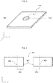
- the hole h1 in the invention is a hole provided with being opened toward the plate thickness direction of the molded article and, for example, a hole shown by h1 in FIG. 1 may be mentioned.
- the hole h1 is preferably a through hole.
- the shape of the hole h1 is not particularly limited and the shape of the hole viewed from the plate thickness direction may be, for example, circular, elliptic, any of various polygonal shapes such as triangular shape or rectangular shape, or an indefinite shape.
- a preferable shape is a circular, elliptic, or triangular shape and a more preferable shape is a circular shape.
- the shape is preferably a circular shape having a diameter of 1 mm or more and 100 mm or less, more preferably a circular shape having a diameter of 5 mm or more and 50 mm or less.
- the role of the hole h1 is not particularly limited but, for example, there are a role of making a fastening rod pass through the hole, a role for determining a reference position, a role for avoiding the interference with another member, and other roles.
- the region a defined in the invention is a region surrounded with an inner wall face W1 of the hole h1 and an imaginary outer wall face W2 depicted in parallel to the inner wall face W1 in the position having a distance Lw (Lw is a weight-average fiber length of the carbon fibers contained in the molded article) from the inner wall face W1 (e.g., 201 in FIG. 2 ).
- the region a is preferably a region surrounded with an inner wall face W1 of the hole h1 and an imaginary outer wall face W2 depicted in parallel to the inner wall face W1 in the position of 20 mm from the inner wall face W1.
- a figure formed by the inner wall face W1 and a figure formed by the imaginary outer wall face W2, which are viewed in the plate thickness direction, are similar to each other.
- region a is a region that continues from the inner wall face W1 of the hole h1 and the region a includes portions where the carbon fibers are oriented in three dimensions.
- the linear expansion coefficient C1 of the region a in the plate thickness direction and the linear expansion coefficient C2 of the molded article region other than the region a in the plate thickness direction satisfies a relation of C1/C2 ⁇ 1.
- the linear expansion coefficient is a proportion of a ratio of expansion or contraction of an object caused by an increase or a decrease of temperature to a temperature change, particularly represents a change of length, and is shown by strain per unit temperature.
- the unit is represented by /°C or %/°C. It is also called as a coefficient of linear expansion.
- the measurement of the linear expansion coefficient may be conducted as follows after a test specimen is vacuum-dried at 110°C for 24 hours as a pre-treatment.
- Shape of the test specimen a sample is cut out in a rectangular parallelepiped shape of plate thickness direction ⁇ in-plane direction ⁇ in-plane direction and is compressed (measured) in the plate thickness direction.
- the plate thickness direction is the Z direction in FIG. 1, FIG. 2 , and FIG. 4 .
- Model of testing machine TMA/SS7100 (manufactured by Seiko Instruments Inc.) Temperature increasing rate: 5°C/min Test load: compression load of 49 mN Probe diameter: 2.9 mm Measurement atmosphere: under nitrogen atmosphere (100 ml/min) Test temperature range: 25 to 200°C
- dimensional stability is improved in the region a that is a periphery of the hole h1.
- the linear expansion coefficient is lowered only in the region a that is a periphery of the hole h1, as compared with the linear expansion coefficient of the whole molded article. This is extremely advantageous on production since the linear expansion coefficient may be controlled locally at the peripheral part of the hole, as compared with the case where the dimensional stability in the plate thickness direction of the whole molded article is improved.
- a specific method for achieving C1/C2 ⁇ 1 is not particularly limited but there may be mentioned a method where the hole h0 is provided on the molding material as mentioned later and the molding material is made flow at the time of molding to form the hole h1 and a method where the hole h1 is provided by specifically using a resin having a low linear expansion coefficient only in the region a or by intentionally orienting the carbon fibers toward the plate thickness direction only in the region a.
- the hole h0 is provided on the molding material as mentioned later and the molding material is made flow at the time of molding to form the hole h1.
- the C1/C2 preferably satisfies C1/C2 ⁇ 0.9, more preferably C1/C2 ⁇ 0.7, even more preferably C1/C2 ⁇ 0.5, most preferably C1/C2 ⁇ 0.3.
- a specific value of the linear expansion coefficient C1 is not particularly limited but is preferably 22 ⁇ 10 -5 /°C or less, more preferably 15 ⁇ 10 -5 /°C or less, even more preferably 10 ⁇ 10 -5 /°C or less.
- the linear expansion coefficient C1 is 22 ⁇ 10 -5 /°C or less, for example, in the case where a fastening rod such as a resin rivet is inserted into the hole h1 and fastening is conducted, fastening is stabilized.
- the linear expansion coefficient C2 in the invention preferably satisfies Cm/C2 ⁇ 1, wherein Cm represents the linear expansion coefficient of the thermoplastic resin.
- linear expansion coefficient C2 is larger than the linear expansion coefficient Cm means that the linear expansion coefficient in the plate thickness direction is increased by incorporating the carbon fibers into the thermoplastic resin.
- FIG. 6 shows a specific example.
- FIG. 6 represents a cross-sectional schematic view where the holes h1 of two molded articles of the invention are overlaid and fastened with a rivet.
- two molded articles 101 in FIG. 6
- a rivet made of a resin or the like (602 in FIG. 6 ) is inserted into the holes h1, and the two molded articles are caulked and fastened.
- the caulking and fastening are conducted at a portion including the region a, the dimensional stability of the periphery of the fastened part in the plate thickness direction is excellent.
- the molded article region other than the region a the molded article is prone to expand in the plate thickness direction particularly under a high-temperature region (arrow direction in FIG. 6 ). Thereby, the clearance between the molded articles (101 in FIG. 6 ) is narrowed and thus the sealing effect at the fastened article is increased.
- the linear expansion coefficient of a thermosetting resin is very small as compared to the linear expansion coefficient of a thermoplastic resin.
- the carbon fibers contained in the molded article region other than the region a are randomly dispersed in two dimensions in the in-plane directions and the linear expansion coefficient C3 of the molded article region other than the region a in the in-pane direction is more than 0 and 2.0 ⁇ 10 -5 /°C or less.
- the linear expansion coefficient C3 in the in-plane directions is more preferably 0.10 ⁇ 10 -5 /°C or more and 2.0 ⁇ 10 -5 /°C or less.
- the linear expansion coefficient in the in-plane directions falls within the above range in the whole range of the molded article region other than the region a, and the molded article may be one where the linear expansion coefficient partially falls within the above range.
- the hole h1-2 is another new hole different from the hole h1 and, for example, refers to h1-2 in FIG. 4 .
- the thickness of the molded article of the invention is not particularly limited but usually, is preferably in the range of 0.01 mm to 100 mm, more preferably in the range of 0.01 mm to 10.0 mm, even more preferably in the range of 0.1 mm to 5.0 mm.
- the relationship between the thickness T1 of the molded article in the region a and the thickness T2 of the molded article in the molded article region other than the region a is not particularly limited but preferably satisfies 0.5 ⁇ T1/T2 ⁇ 1.5, preferably 0.8 ⁇ T1/T2 ⁇ 1.2, and even more preferably 0.9 ⁇ T1/T2 ⁇ 1.1 (substantially the same thickness).
- the above thickness does not refer to the thickness of each layer and refers to the thickness of the whole molded article with summing up the thickness of each layer.
- the molded article to be used in the invention may have a single layer structure composed of a single layer or may have a laminated structure where a plurality of layers are laminated.
- the embodiment where the molded article has the above laminated structure may be an embodiment where a plurality of layers having the same composition are laminated or an embodiment where a plurality of layers having compositions different from one another are laminated.
- the volume fraction (Vf) of the carbon fibers contained in the molded article is not particularly limited as mentioned above but the volume fraction Vf1 of the carbon fibers in the region a and the volume fraction Vf2 of the carbon fibers in the molded article region other than the region a satisfies a relation of 0.2 ⁇ Vf1/Vf2.
- the Vf1/Vf2 preferably satisfies a relation of 0.2 ⁇ Vf1/Vf2 ⁇ 1.2, more preferably 0.5 ⁇ Vf1/Vf2 ⁇ 1.0.
- the region a becomes rich in the resin and the mechanical strength of the fastened part decreases.
- a molding material heated up to a first predetermined temperature is charged into a mold set at a second predetermined temperature, and then pressurized and cooled.
- the first predetermined temperature is the melting temperature or higher and the second predetermined temperature is lower than the melting temperature.
- the first predetermined temperature is the glass transition temperature or higher and the second predetermined temperature is lower than the glass transition temperature.
- the cold pressing method includes at least the following steps A-1) and A-2).
- Step A-1) a step of heating the molding material up to a temperature in a range of the melting temperature to decomposition temperature of thermoplastic resin when the resin is crystalline, while in a range of the glass transition temperature to decomposition temperature when the resin is amorphous.
- Step A-2) a step of disposing the molding material heated in the step A-1) in a mold adjusted to a temperature lower than the melting temperature of thermoplastic resin when the resin is crystalline, while a temperature lower than the glass transition temperature when the resin is amorphous, and applying pressure to the mold.
- one (single) or two or more molding materials can be used to suit the plate thickness of a target molded article.
- two or more molding materials may be laminated in advance and heated, or heated molding materials may be laminated and then charged into a mold, or the heated molding materials may be laminated in a mold one by one.
- the lamination is preferably carried out before charging the molding materials into the mold.
- a shaping step wherein the molding material is shaped into the shape of the cavity of the mold to be used in the step A-2) in advance before the step A-2) by the use of a shaping mold other than the mold to be used in the step A-2).
- the step A-2) is a step of applying pressure to the molding material to obtain a molded article having a desired shape.
- the molding pressure at this time is not particularly limited but is preferably less than 20 MPa, more preferably 10 MPa or less.
- the method for producing the molded article of the invention is preferably a method for producing a molded article by cold pressing, the molded article including carbon fibers and a thermoplastic resin, the molded article being provided with a hole h1, wherein the method includes:
- the method for producing the molded article of the invention is a method for producing a molded article by cold pressing, the molded article including carbon fibers having a maximum fiber length Lmax and a thermoplastic resin, the molded article being provided with a hole h1, wherein the method includes:
- the method for producing a molded article of the invention is excellent in accuracy of the hole h1 to be formed.
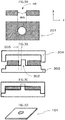
- the hole h0 of the molding material is an open hole h0 previously provided at a place corresponding to the hole h1 of the molded article. For example, it is a hole h0 shown in FIG. 3A .
- a cutting tool such as a pierce die, a Thomson blade, a drill, or an end mill, water jetting, or laser cutting can be used.
- the hole-forming member for forming the hole h1 at a desired position of the molded article may be provided on at least either one of a pair of male and female molds (i.e., an upper mold or a lower mold), and, for example, a protrusion (302) of a lower mold as shown in FIG. 3B can be exemplified.
- the hole-forming member is provided by disposing a pin on the mold and is called a core pin in some cases.
- FIG. 3 An example of the mold for producing the molded article is shown in FIG. 3 as a cross-sectional view thereof.
- the mold is composed of a pair of female and male molds (303, 304), i.e., an upper mold and a lower mold attached to a pressing device (not shown in the figure), and usually, one of them, optionally both of them are movable to the opening and closing direction of the molds (in the figure, the male mold is fixed and the female mold is movable).
- molds each have a cavity face corresponding to a product shape.
- a hole-forming member for forming an opening in a predetermined position a hole-forming member which is movable to the opening and closing direction of the molds in the molds and has the same cross-sectional shape as the target hole h1 of the molded article is provided corresponding to the position of the target hole h1 of the molded article.
- the mold on which the hole-forming member is provided may be any of the male and female molds but, for facilitating the supply of the molding material that is in a softened state by pre-heating, it is preferred to provide the hole-forming member on the mold at the side to which the molding material is disposed.
- the hole-forming members may be provided on both of the male and female molds so that the end faces of the hole-forming members come into contact while they face to each other.
- Both male and female molds (303, 304) are made in an open state and a molding material (301) is placed on a cavity face of the male mold (303).
- a molding material (301) is placed on the molding material ( FIG. 3 ) and the molding material (301) is placed on the lower mold with inserting the hole-forming member (302) into the hole h0 ( FIG. 3B ).
- the molding material having the hole h0 is disposed in the mold so as to correspond to the hole-forming member specifically means that the hole-forming member is disposed with passing though the hole h0 of the molding material.
- the molded article having the hole h1 is obtained by opening the both male and female molds and taking out the molded article.
- the average distance Lf between the inner wall face W0 of the hole h0 of the molding material and the hole-forming member satisfies 0 ⁇ Lf ⁇ 10t. This means that, in the case where the thickness of the molding material is large, a flow distance of the molding material can be lengthened. For example, when the thickness of the molding material is 2.5 mm, the average distance Lf may satisfy 0 ⁇ Lf ⁇ 25 mm.
- An upper limit of the average distance Lf is more preferably less than 7t, further preferably less than 6t, even more preferably 3t or less.
- the thickness t of the molding material is not particularly limited but usually, is preferably in the range of 0.01 mm to 100 mm, preferably in the range of 0.01 mm to 10.0 mm, more preferably in the range of 0.1 mm to 5.0 mm.
- the above thickness t does not refer to the thickness of each layer but refers to the thickness of the whole molding material with summing up the thickness of each layer.
- the molding material in the invention may have a single layer structure composed of a single layer or may have a laminated structure where a plurality of layers are laminated.
- the embodiment where the molding material has the above laminated structure may be an embodiment where a plurality of layers having the same composition are laminated or an embodiment where a plurality of layers having compositions different from one another are laminated.
- the average distance Lf between the inner wall face W0 of the hole h0 of the molding material and the hole-forming member is more than 0 and the maximum fiber length Lmax or less.
- the distance between the inner wall face W0 of the hole h0 of the molding material and the hole-forming member is a distance from the inner wall face W0 to the hole-forming member, for example, as shown by 305 in FIG. 3B . Even when the hole-forming member (302) and the hole h0 have indefinite shapes, or when the hole-forming member (302) is unevenly disposed, the distances from the inner wall face W0 to the hole-forming member is averaged as the average distance thereof.
- a lower limit of the average distance Lf between an inner wall face W0 of the hole h0 of the molding material and the hole-forming member is more preferably one tenth or more of the maximum fiber length Lmax, further preferably 3 mm or more, even more preferably 5 mm or more.
- the inner wall face W0 of the hole h0 of the molding material and the hole-forming member In a case where the average distance Lf between the inner wall face W0 of the hole h0 of the molding material and the hole-forming member is controlled to more than 0 mm when the molding material is disposed in the mold, the inner wall face W0 of the hole h0 approaches to the hole-forming member while the carbon fibers and the resin both flow at molding, thereby the inner wall face W1 of the hole h1 of the molded article is formed.
- the flowing portion is changed into a state that the carbon fibers are oriented to three-dimensional direction including the plate thickness direction (Z direction in FIG. 2 ).
- the carbon fibers are maintained in a state that they are randomly dispersed in two dimensions in the in-plane directions.
- the carbon fibers are preferably a mixture of carbon fiber bundles (A) each constituted by single fibers of a critical single fiber number or more, the critical single fiber number being defined by the above formula (1), and carbon fiber bundles (B1) each constituted by single fibers of less than the critical single fiber number and/or single carbon fibers (B2), the proportion of the carbon fiber bundles (A) to all the fibers is preferably more than 5 Vol% and less than 99 Vol%, and the average number (N) of single fibers in the carbon fiber bundles (A) preferably satisfies the requirement of the above formula (2).
- An upper limit of the average distance Lf between the inner wall face W0 of the hole h0 of the molding material and the hole-forming member is preferably 10t (t is thickness of the molding material) or less, more preferably the maximum fiber length Lmax or less, even more preferably 30 mm or less, particularly preferably 20 mm or less.
- a cutting step of cutting individual molded articles can be omitted by providing the hole at the time of molding. Furthermore, since the volume fraction of the fibers at the periphery (region a) of the hole h1 is relatively high, dimensional stability is good and high circularity of the hole provided on the molded article is maintained.
- the projection area of the hole h0 that is a size of the hole h0 is preferably 101% or more and 2,000% or less of the projection area of the hole-forming member.
- the projection area is a projection area to the drawing direction of the molds and is the Z direction shown in FIG. 3A .
- the projection area of the hole h0 is 2,000% or less of the projection area of the hole-forming member, the periphery of the hole is less prone to be thined, variation in the distance between the hole h0 and the hole-forming member is less prone to occur, and thus it becomes easy to keep the hole accuracy.
- the hole-forming member is provided on the lower mold, fixing force of the molded article to the lower mold can be enhanced, the position of the molded article at the opening of the molds becomes definite, and thus the take-out of the molded article can be stably performed. Thereby, the method for producing the molded article can have an excellent process passing ability.
- the projection area of the hole h0 is preferably 105% or more and 1,700% or less, more preferably 110% or more and 1,500% or less of the projection area of the hole-forming member.
- Vf 100 ⁇ volume of carbon fibers / [ ( volume of carbon fibers ) + volume of thermoplastic resin ]
- each site of the molded article was cut and taken out and then measured.
- the weight-average fiber length of the carbon fibers contained in a molding material can be also measured by the same method as mentioned above.
- test specimen After a test specimen was vacuum-dried at 110°C for 24 hours as a pre-treatment, measurement was performed under the following measurement conditions.
- the compression direction at the time of measuring the linear expansion coefficient is each direction in the following samples (i) to (iii).
- test specimens were cut out of the inner wall face W1 of the hole h1 toward outside of the normal direction of the inner wall face W1 and measured and then an average thereof was determined.
- a test specimens were cut out at the places 50 mm or more apart from the region a.
- a tensile strength decrease rate (%) at the place including the hole h1 with respect to the tensile strength at the place not including the hole h1 was calculated based on the following formula.
- Tensile strength decrease rate % [ ( Tensile strength at place not including hole h 1 ) ⁇ Tensile strength at place including hole h 1 ] ⁇ ( Tensile strength at portion not including h 1 ) ⁇ 100
- a resin rivet As the resin rivet, a clinch rivet (Nylon-6, manufactured by Mitsukawa Co., Ltd., Item No. CR32-2-1) was used.
- the periphery of the hole h1 of a molded article produced was observed and a range where the molding material flowed was measured with a ruler. Distances were measured from the hole h1 (perfect circle) in the normal direction in 12 directions at even intervals and an average value (mm) was calculated. Incidentally, the range where the molding material flowed was visually confirmed.
- Carbon fibers "Tenax” (registered trademark) STS40-24KS (average fiber diameter: 7 ⁇ m, single yarn number: 24,000) manufactured by Toho Tenax Co., Ltd., which had been cut to an average fiber length of 20 mm were used as carbon fibers.
- Nylon-6 resin A1030 manufactured by Unichika, Ltd. was used.
- the obtained molding material precursor was heated at 2.0 MPa for 5 minutes with a pressing device heated to 260°C to obtain a molding material (i) having an average thickness of 2.5 mm.
- the carbon fibers contained therein were analyzed. As a result, the following were found: the critical single fiber number defined by the above formula (1) was 86; the average number (N) of single fibers in carbon fiber bundles (A) each constituted by the single fibers of the critical single fiber number or more was 820; and the proportion of the carbon fiber bundles (A) each constituted by the single fibers of the critical single fiber number or more was 80 Vol% of all the carbon fibers. Moreover, the volume fraction (Vf) of the carbon fibers was 35%, the fiber lengths of the carbon fibers were constant, and the weight-average fiber length was 20 mm.
- Vf volume fraction
- the molding material (ii) is one having a portion where a part of the molding material (i) is replaced by the Nylon-6 resin.
- a molding material was prepared in the same manner as in Example 1 except that the molding material precursor was manufactured with increasing the degree of opening of fibers at the time of manufacturing the molding material precursor, and the molding material was regarded as a molding material (iii). With respect to the molding material obtained, the carbon fibers contained therein were analyzed. As a result, the following were found: the critical single fiber number defined by the above formula (1) was 86; the average number (N) of single fibers in carbon fiber bundles (A) each constituted by the single fibers of the critical single fiber number or more was 420; and the proportion of the carbon fiber bundles (A) each constituted by the single fibers of the critical single fiber number or more was 35 Vol% of all the carbon fibers. Moreover, the volume fraction (Vf) of the carbon fibers was 35%, the fiber lengths of the carbon fibers were constant, and the weight-average fiber length was 20 mm.
- a molding material was prepared in the same manner as in Example 1 except that the molding material precursor was manufactured with increasing the degree of opening of fibers at the time of manufacturing the molding material precursor, and the molding material was regarded as a molding material (iv). With respect to the molding material obtained, the carbon fibers contained therein were analyzed. As a result, the following were found: the critical single fiber number defined by the above formula (1) was 86; the average number (N) of single fibers in carbon fiber bundles (A) each constituted by the single fibers of the critical single fiber number or more was 100; and the proportion of the carbon fiber bundles (A) each constituted by the single fibers of the critical single fiber number or more was 5 Vol% of all the carbon fibers. Moreover, the volume fraction (Vf) of the carbon fibers was 35%, the fiber lengths of the carbon fibers were constant, and the weight-average fiber length was 20 mm.
- a molding material was prepared in the same manner as in Production Example 1 except that the molding material precursor was manufactured with regulating the degree of opening of fibers at the time of manufacturing the molding material precursor, and the molding material was regarded as a molding material (v).
- the carbon fibers contained therein were analyzed.
- the critical single fiber number defined by the above formula (1) was 86;
- the average number (N) of single fibers in carbon fiber bundles (A) each constituted by the single fibers of the critical single fiber number or more was 200;
- the proportion of the carbon fiber bundles (A) each constituted by the single fibers of the critical single fiber number or more was 10 Vol% of all the carbon fibers.
- the volume fraction (Vf) of the carbon fibers was 35%, the fiber length of the carbon fibers was constant, and the weight-average fiber length was 20 mm. The results are shown in Table 1.
- a molding material was prepared in the same manner as in Production Example 1 except that the molding material precursor was manufactured with adjusting the carbon fiber areal weight and the Nylon resin areal weight so that the average thickness of the molding material became 1 mm, and the molding material was regarded as a molding material (vi).
- the molding material (i) obtained in Production Example 1 was cut out into a size of 95 mm ⁇ 195 mm and a hole h0 was provided at the position shown in FIG. 3 .
- the diameter of the hole h0 was 40 mm. After this was dried with a hot-air drier at 120°C for 4 hours, it was heated to 275°C with an infrared heater.
- molds molds having a flat molding cavity of 100 mm ⁇ 200 mm were used, to which a hole-forming member was disposed at the position shown in FIG. 3 .
- the projection area of the hole-forming member in the drawing direction of the molds was 137 mm 2 .
- the shape of the hole-forming member when viewed from the drawing direction of the molds was a perfect circle having a diameter of 13.20 mm.
- the temperature of the molds was set at 140°C, and the molding material which had been heated was introduced into the molds, and was pressed at a pressing pressure of 10 MPa for 1 minute to obtain a molded article having a hole h1 (perfect circle shape). Moreover, the operation was repeated 100 times to manufacture 100 pieces of the molded article having a hole h1 and the accuracy of the hole h1 was evaluated as mentioned above. The results are shown in Table 2.
- a molded article was obtained by performing press-molding in the same manner as in Example 1, except that the diameter of the hole h0 was changed to a diameter of 30 mm. The results are shown in Table 2.
- a molded article was obtained by performing press-molding in the same manner as in Example 1, except that the diameter of the hole h0 was changed to a diameter of 16 mm. The results are shown in Table 2.
- a molded article was obtained by performing press-molding in the same manner as in Example 1, except that the diameter of the hole h0 was changed to a diameter of 14 mm. The results are shown in Table 2.
- a molded article was obtained by performing press-molding in the same manner as in Example 1, except that the molding material (iii) was used. The results are shown in Table 2.
- a molded article was obtained by performing press-molding in the same manner as in Example 1, except that the molding material (v) was used. The results are shown in Table 2.
- a molded article was obtained by performing press-molding in the same manner as in Example 1, except that the diameter of the hole h0 was changed to 50 mm. The results are shown in Table 2.
- a molded article was obtained by performing press-molding in the same manner as in Example 1, except that the diameter of the hole h0 was changed to 62 mm. The results are shown in Table 3.
- a molded article was obtained by performing press-molding in the same manner as in Example 1, except that the diameter of the hole-forming member (perfect circle shape) was changed to 5.20 mm and the diameter of the hole h0 was changed to 30 mm. The results are shown in Table 3.
- a molded article was obtained by performing press-molding in the same manner as in Example 1, except that the diameter of the hole-forming member (perfect circle shape) was changed to 30.20 mm and the diameter of the hole h0 was changed to 62 mm. The results are shown in Table 3.
- the shape of the hole-forming member was made a square having a side of 6 mm and a molding material was disposed with providing a hole h0 along the shape of the hole-forming member so that a flow distance of the molding material became 10 mm (see FIG. 7 ).
- a molded article was obtained by performing press in the same manner as in Example 1, except the above. The results are shown in Table 4.
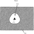
- the shape of the hole-forming member was made an equilateral triangle having a side of 6 mm and a molding material was disposed with providing a hole h0 along the shape of the hole-forming member so that a flow distance of the molding material became 10 mm (see FIG. 8 ).
- a molded article was obtained by performing press in the same manner as in Example 1, except the above. The results are shown in Table 4.
- a molded article was obtained by performing press in the same manner as in Example 1, except that the molding material (vi) was used and the diameter of the hole h0 (perfect circle shape) was changed to 14 mm. The results are shown in Table 4.
- a molded article was obtained by performing press in the same manner as in Example 1, except that two molding materials (i) were overlaid to change the thickness of the molding material to 5 mm. The results are shown in Table 4.
- a molded article was obtained by performing press in the same manner as in Example 1, except that four molding materials (i) were overlaid to change the thickness of the molding material to 10 mm and the diameter of the hole h0 (perfect circle shape) was changed to 150 mm. The results are shown in Table 4.
- the molding material (i) was cut out into a size of 95 mm ⁇ 195 mm and a hole h0 was not provided. After it was dried with a hot-air drier at 120°C for 4 hours, it was heated to 275°C with an infrared heater. As molds, use was made of molds having a flat molding cavity of 100 mm ⁇ 200 mm, to which a hole-forming member was not disposed. The temperature of the molds was set at 140°C, and the molding material which had been heated was introduced into the molds and was pressed at a pressing pressure of 10 MPa for 1 minute to obtain a molded article having no hole.
- the obtained molded article was processed using a 3-axis machining center.
- a helix angle was 0°
- a rake angle was 10°
- the number of the blades (t) was 4, and a diameter was 6 mm
- cutting was performed (a feed speed was 800 mm/min since the number of rotations was 8,000 (1/min)) to provide a perfect circular hole having a diameter of 13.2 mm on the molded article. Since the hole was provided by cutting, one step increased and the productivity was poor.
- Table 3 The results are shown in Table 3.
- the molding material (ii) was cut out into a size of 95 mm ⁇ 195 mm including the portion replaced by the Nylon-6 resin, and a hole h0 (diameter: 40 mm) was provided in the position shown in FIG. 3 at the portion (60 mm ⁇ 60 mm) replaced by the Nylon-6 resin. After this was dried with a hot-air drier at 120°C for 4 hours, it was heated to 275°C with an infrared heater. Molds having a flat molding cavity of 100 mm ⁇ 200 mm was used as molds, to which a hole-forming member was disposed in the position shown in FIG. 3 . Incidentally, the projection area of the hole-forming member to the drawing direction of the molds was 137 mm 2 .
- the temperature of the molds was set at 140°C, and the molding material which had been heated was introduced into the molds, and was pressed at a pressing pressure of 10 MPa for 1 minute to obtain a molded article. Moreover, 100 pieces of the molded article were continuously cut with an end mill but the blades of the end mill was gradually worn on this occasion. As a result, at the time of making the final 10 pieces, the target perfect circular shape was not able to manufacture (smaller than the target perfect circular shape) due to wear. The results are shown in Table 3.
- the injection-molded plate obtained in Production Example 3 was subjected to cutting, using an end mill having spiral cutting blades where a helix angle was 0°, a rake angle was 10°, the number of the blades (t) was 4, and a diameter was 6 mm, cutting was performed (a feed speed was 800 mm/min since the number of rotations was 8,000 (1/min)) to provide a perfect circular hole having a diameter of 13 mm on the injection-molded plate.
- the results are shown in Table 3.
- a molded article was obtained by performing press-molding in the same manner as in Example 1, except that the molding material (iv) was used. The results are shown in Table 3.
- Molding material Molding material i) Molding material (ii) Molding material (iii) Molding material (iv) Molding material (v) Molding material (vi) Carbon fiber Weight-average fiber length Lw (mm) 20 20 20 20 20 20 20 20 20 20 Maximum fiber length Lmax(mm) 20 20 20 20 20 20 20 20 20 20 20 20 20 20 20 Fiber form Random in two dimensions Random in two dimensions Random in two dimensions Random in two dimensions Random in two dimensions Random in two dimensions Random in two dimensions Average fiber number (fibers) 820 820 420 100 200 820 Proportion of carbon fiber bundles (A) (Vol%) 80 80 35 5 10 80 Thermoplastic rein Type Polyamide-6 Polyamide-6 Polyamide-6 Polyamide-6 Polyamide-6 Polyamide-6 Polyamide-6 Linear expansion coefficient Cm ( ⁇ 10 -5 /°C) 10 10 10 10 10 10 10 10 10 Average thickness (mm)
- FIG. 8 perfect circle perfect circle perfect circle Diameter (mm) 14 40 150 Projection area (mm 2 ) 590 494 154 1257 17671 Hole-forming member Shape square equilateral triangle perfect circle perfect circle Diameter (mm) 6 6 13.20 13.20 13.20 Projection area (mm 2 ) 36 18 137 137 137 Projection area of hole h0/ Projection area of hole-forming member (%) 1,639 2,744 112 918 12,913 Average distance between inner wall face of hole h0 and hole-forming member Lf (mm) 10 10 0.4 13.4 68.4 Thickness t of molding material (mm) 2.5 2.5 1 5 10 Lf/t 4 4 0.4 2.68 6.84 Molded article C1 ( ⁇ 10 -5 /°C) 7.6 7.6 26 16 5 C2 ( ⁇ 10 -5 /°C) 28.5 28.5 28.5 28.5 28.5 C1/C2 0.27 0.27 0.91 0.56 0.18 C3 ( ⁇ 10 -5 /°C) 0.7 0.7 0.6 0.7
- the molded articles and the production method of the present invention can be used for various constituent members, for example, interior or exterior boards and constituent members for automobiles, and for frames or housings of various electrical products or machines, or the like. Preferably, they can be utilized as automobile parts.
Abstract
Description
- The present invention relates to a molded article provided with a hole, the molded article including carbon fibers and a thermoplastic resin, and a method for producing the same.
- In recent years, a so-called fiber-reinforced resin molded articles each including carbon fibers and a thermoplastic resin are attracting attention. These fiber-reinforced resin molded articles are excellent in mechanical properties owing to the presence of the carbon fibers in the thermoplastic resin and are attracting attention as structural materials for automobiles and the like. These fiber-reinforced resin molded articles can be molded into target shapes using compression molding or the like including cold pressing. Moreover, as the fiber-reinforced resin molded article, there is also well known a molded article having a hole at a part of the molded article.
- As a method for producing such a fiber-reinforced resin molded article having a hole, for example,
Patent Document 1 describes an invention where an opening part corresponding to an opening hole of the molded article is previously provided on a molding material, subsequently pre-heating is performed, and the molding material is subjected to compression molding to obtain the molded article. - Moreover,
Patent Document 2 discloses a fastened structure wherein a peripheral part of a through hole is intentionally formed as a weak part and is made easy to destroy. -
- Patent Document 1:
JP-A-10-100175 - Patent Document 2:
JP-A-2015-44339 - However, in the method described in
Patent Document 1, at the time of flow molding of the molded article provided with an opening hole, the fibers contained in the molding material does not flow and a peripheral part of the opening hole is formed by a flow of the resin alone, so that the peripheral part of the opening hole becomes in a resin-rich state and thus the mechanical strength of the peripheral part of the opening hole decreases. - On the other hand, in the method described in
Patent Document 2, since a linear expansion coefficient is the same in a peripheral part of the hole and in the other parts, it is difficult to locally improve dimensional stability of the hole part. - Accordingly, an object of the present invention is to provide a molded article having a hole in which both of the mechanical strength and the dimensional stability of the hole peripheral part are achieved, and a method for producing the same.
- For solving the above problems, the present invention provides the following means.
-
- [1] A molded article including carbon fibers and a thermoplastic resin, the molded article being provided with a hole h1, the molded article having a region a around the hole h1,
wherein a linear expansion coefficient C1 of the region a in the plate thickness direction and a linear expansion coefficient C2 of a molded article region other than the region a in the plate thickness direction satisfies a relation of C1/C2<1, and
a volume fraction Vf1 of the carbon fibers in the region a and a volume fraction Vf2 of the carbon fibers in the molded article region other than the region a satisfies a relation of 0.2<Vf1/Vf2. - [2] The molded article according to [1], wherein the carbon fibers are discontinuous carbon fibers having a weight-average fiber length Lw and
the region a is a region surrounded with an inner wall face W1 of the hole h1 and an imaginary outer wall face W2 depicted in parallel to the inner wall face W1 in a position having a distance Lw from the inner wall face W1. - [3] The molded article according to [1] or [2], wherein the volume fraction Vf1 of the carbon fibers in the region a and the volume fraction Vf2 of the carbon fibers in the molded article region other than the region a satisfies a relation of 0.2<Vf1/Vf2<1.2.
- [4] The molded article according to any one of [1] to [3], wherein the linear expansion coefficient Cm of the thermoplastic resin satisfies Cm/C2<1.
- [5] The molded article according to any one of [1] to [4], wherein the linear expansion coefficient C1 is 22×10-5/°C or less.
- [6] The molded article according to any one of [1] to [5], wherein the weight-average fiber length Lw of the carbon fibers is 1 to 100 mm.
- [7] The molded article according to [6], wherein the carbon fibers contained in the molded article region other than the region a are randomly dispersed in two-dimensions within in-plane directions; and
the molded article region other than the region a has a linear expansion coefficient C3 in the in-pane direction of more than 0 and 2.0×10⁻⁵/°C or less. - [8] The molded article according to any one of [1] to [7], wherein, the carbon fibers contained in the molded article are mixture of carbon fiber bundles (A) each constituted by a critical single fibers of a critical single fiber number defined by the following formula (1) or more, and carbon fiber bundles (B1) each constituted by single fibers of less than the critical single fiber number and/or single carbon fibers (B2), a proportion of the carbon fiber bundles (A) to all the fibers is more than 5 Vol% and less than 99 Vol%, and an average number (N) of single fibers in the carbon fiber bundles (A) satisfies the requirement of the following formula (2):


- [9] A method for producing a molded article by cold pressing, the molded article including carbon fibers and a thermoplastic resin, the molded article being provided with a hole h1, the method including:
- boring a hole h0 into a molding material having a thickness t; and
- disposing the molding material in a pair of male and female molds, at least one of the male and female molds having a hole-forming member for forming the hole h1, after the boring of the hole h0 so that the hole h0 corresponds to the hole-forming member, wherein
- at the time of disposing the molding material in the molds, an average distance Lf between an inner wall face W0 of the hole h0 of the molding material and the hole-forming member is 0<Lf<10t,
- wherein the molded article has a region a around the hole h1, a linear expansion coefficient C1 of the region a in the plate thickness direction and a linear expansion coefficient C2 of a molded article region other than the region a in the plate thickness direction satisfies relation of C1/C2<1, and a volume fraction Vf1 of the carbon fibers in the region a and a volume fraction Vf2 of the carbon fibers in the molded article region other than the region a satisfies a relation of 0.2<Vf1/Vf2.
- [10] The method for producing a molded article according to [9], wherein, at the time of disposing the molding material in the molds, the average distance Lf between the inner wall face W0 of the hole h0 of the molding material and the hole-forming member is more than 0 mm and Lmax or less,
wherein Lmax is a maximum fiber length of the carbon fibers. - [11] The method for producing a molded article according to [9] or [10], wherein the carbon fibers are discontinuous carbon fibers having a weight-average fiber length Lw and
the region a is a region surrounded with the inner wall face W1 of the hole h1 and an imaginary outer wall face W2 depicted in parallel to the inner wall face W1 in a position having a distance Lw from the inner wall face W1. - [12] The method for producing a molded article according to any one of [9] to [11], wherein, at the time of disposing the molding material in the molds, the average distance Lf between the inner wall face W0 of the hole h0 of the molding material and the hole-forming member is one tenth or more of the maximum fiber length Lmax of the carbon fibers and Lmax or less.
- [13] The method for producing a molded article according to any one of [9] to [12], wherein a projection area of the hole h0 in a drawing direction of the molds is 101% or more and 2,000% or less with respect to a projection area of the hole-forming member in the drawing direction of the molds.
- According to the molded article provided with a hole and the method for producing the same in the invention, the linear expansion coefficient of a hole peripheral part in the plate thickness direction can be designed to be low without decreasing the mechanical properties of the hole peripheral part, and the dimensional stability at the hole peripheral part in the plate thickness direction becomes excellent.
-
-
FIG. 1 is a schematic view illustrating an example of the molded article in the invention. -
FIG. 2 is a cross-sectional view of "103-103''' inFIG. 1 . -
FIG. 3 is a schematic view illustrating a method for producing an example of the molded article. -
FIG. 4 is a schematic view illustrating an example of the molded article having two holes. -
FIG. 5 is a schematic view illustrating a method for producing an example of the molded article having two holes. -
FIG. 6 is a schematic view where two molded articles each provided with a hole h1 in the invention are overlaid and fastened. -
FIG. 7 is a schematic view illustrating a hole h0 of the molding material and the hole-forming member in Example 11. -
FIG. 8 is a schematic view illustrating a hole h0 of the molding material and the hole-forming member in Example 12. - The "molding material" shown in the present description refers to a material before molding the molded article and is also simply referred to as "molding material".
- As the carbon fibers to be used in the present invention, there are generally known polyacrylonitrile (PAN)-based carbon fibers, petroleum-coal pitch-based carbon fibers, rayon-based carbon fibers, cellulose-based carbon fibers, lignin-based carbon fibers, phenol-based carbon fibers, vapor-grown carbon fibers, and the like. In the invention, carbon fibers of any of these types can be suitably used.
- Of these, in the invention, from the viewpoint of excellent tensile strength, polyacrylonitrile (PAN)-based carbon fibers are preferably used. In the case of using PAN-based carbon fibers as the carbon fibers, the tensile modulus thereof is preferably in the range of 100 GPa to 600 GPa, more preferably in the range of 200 GPa to 500 GPa, even more preferably in the range of 230 GPa to 450 GPa. The tensile strength thereof is preferably in the range of 2,000 MPa to 10,000 MPa, more preferably in the range of 3,000 MPa to 8,000 MPa.
- The carbon fibers to be used in the invention may be ones which have a sizing agent adherent to the surface thereof. In the case of using carbon fibers having a sizing agent adherent thereto, the type of the sizing agent can be suitably selected in accordance with the type of the carbon fibers and the type of the matrix resin, and is not particularly limited.
- The fiber length of the carbon fibers to be used in the invention is not particularly limited and continuous fibers and discontinuous carbon fibers can be used.
- The carbon fibers to be used in the invention are preferably discontinuous carbon fibers having a weight-average fiber length Lw of 1 to 100 mm. The weight-average fiber length of the discontinuous carbon fibers is preferably 3 to 80 mm, and even more preferably 5 to 60 mm. When the weight-average fiber length is 100 mm or less, the flowability of the molding material is not decreased and a desirable molded article shape is obtained at the time of press molding. On the other hand, when the weight-average fiber length is 1 mm or more, the mechanical strength of the molded article is not decreased and thus the case is preferable. Moreover, the discontinuous carbon fibers having a weight-average fiber length Lw of 1 to 100 mm and continuous carbon fibers may be used in combination.
- In the invention, carbon fibers which differ in fiber length from one another may be used in combination. In other words, the carbon fibers to be used in the invention may have a single peak or a plurality of peaks of the weight-average fiber length.
- The average fiber length of the carbon fibers can be determined, for example, by randomly extracting 100 carbon fibers from the molded article, measuring the length of each of the carbon fibers with a vernier caliper or the like down to the order of 1 mm, and calculating the average length on the basis of the following formula (a).
- Incidentally, when the length of each carbon fiber is expressed by Li and the number of carbon fibers measured is expressed by j, then the number-average fiber length (Ln) and the weight-average fiber length (Lw) are determined using the following formulae (a) and (b).


- In the case where the fiber length is a constant length, the number-average fiber length and the weight-average fiber length become the same value.
- The extraction of carbon fibers from the molded article can be conducted, for example, by subjecting the molded article to a heat treatment of about 500°C for 1 hour to remove the resin in an oven.
- The fiber diameter of the carbon fibers to be used in the invention may be appropriately determined in accordance with the type of the carbon fibers, and is not particularly limited. Usually, the average fiber diameter is preferably in the range of 3 µm to 50 µm, more preferably in the range of 4 µm to 12 µm, even more preferably in the range of 5 µm to 8 µm. The average fiber diameter herein means the diameter of the single carbon fibers. Consequently, in the case of carbon fibers which are in the form of fiber bundles, that term means not the diameter of the fiber bundles but the diameter of the carbon fibers (single fibers) constituting the fiber bundles. The average fiber diameter of carbon fibers can be determined, for example, by the method described in JIS R-7607:2000.
- The volume fraction of the carbon fibers (hereinafter sometimes referred to simply as "Vf") contained in the molded article (the whole molded article including both of the region a and the molded article region other than the region a), defined by the following formula(c), is not particularly limited but the volume fraction (Vf) of the carbon fibers in the molded article is preferably 10 to 60 Vol%, more preferably 20 to 50 Vol%, even more preferably 25 to 45 Vol%.

- In the case where the volume fraction (Vf) of the carbon fibers in the molded article is 10 Vol% or more, desired mechanical properties are easily obtained. On the other hand, in the case where the volume fraction (Vf) of the carbon fibers in the molded article does not exceed 60 Vol%, flowability at the time of the use in press molding or the like is satisfactory and a desired molded article shape is easily obtained.
- Incidentally, the relationship between the volume fraction Vf1 of the carbon fibers in the region a and the volume fraction Vf2 of the carbon fibers in the molded article region other than the region a will be mentioned later.
- The areal weight of the carbon fibers in the molded article is not particularly limited. However, the areal weight is usually 25 g/m2 to 10,000 g/m2.
- Regardless of the type of the carbon fibers, the carbon fibers to be used in the invention may be in a single fiber form composed of a single fiber or may be in the form of fiber bundles each composed of a plurality of single fibers.
- The carbon fibers to be used in the invention may contain ones in the form of fiber bundles. In the case of using carbon fibers in the form of fiber bundles, the number of single fibers constituting each fiber bundle may be substantially even in each fiber bundle or may be different from one another.
- In the case where the carbon fibers to be used in the invention are in the form of fiber bundles, the number of the single fibers constituting each fiber bundle is not particularly limited. However, the number thereof is usually in the range of 1,000 to 100,000.
- In general, carbon fibers are available in the form of fiber bundles each composed of several thousands to tens of thousands of filaments gathered together. When the carbon fibers are used as such, portions where fiber bundles are entangled become locally thick and thus it is sometimes difficult to obtain a thin molded article. Therefore, such carbon fibers are usually used after the fiber bundles are widened or opened.
- In the case of opening the fiber bundles before use, a degree of opening in the opened fiber bundles is not particularly limited. It is, however, preferred to control the degree of opening in the fiber bundles so that the carbon fibers to be used include carbon fiber bundles each composed of a specific number or more of carbon fibers and carbon fibers (single fibers) or carbon fiber bundles each composed of less than the specific number of carbon fibers. In this case, specifically, carbon fiber bundles (A) each constituted by single fibers of a critical single fiber number or more, the critical single fiber number being defined by the following formula (1), and carbon fiber bundles (B1) each constituted by single fibers of less than the critical single fiber number and/or single carbon fibers (B2) are mixed, and the proportion of the carbon fiber bundles (A) to all the fibers is preferably more than 0 Vol% to 99 Vol%, more preferably more than 5 Vol% to 99 Vol%, even more preferably 20 Vol% or more to less than 99 Vol%, particularly preferably 30 Vol% or more to less than 95 Vol%. It is preferred that the proportion of the carbon fiber bundles (A) to the total amount of the fibers falls within the above range. Further, the average number (N) of single fibers in the carbon fiber bundles (A) preferably satisfies the following formula (2).


- As mentioned above, when the carbon fiber bundles each composed of a specific number or more of carbon fibers and the opened carbon fibers or carbon fiber bundles other than the above bundles are made co-present in a specific ratio, it becomes possible to increase the content of the carbon fibers in the molded article, i.e., the volume fraction (Vf) of the fibers, so that the case is preferable.
- Moreover, in the case where the average number (N) of single fibers in the carbon fiber bundles (A) is larger than 0.6×10⁴/D2, a higher volume fraction (Vf) of the carbon fibers is easily obtained and thus a fiber-reinforced plastic having an excellent strength is easily obtained. Furthermore, in the case where the average number (N) of single fibers in the carbon fiber bundles (A) is smaller than 6×10⁵/D2, a locally thick part is less prone to be generated and voids are less prone to occur. A more preferred range of the average number (N) of single fibers is 0.6×10⁴/D2<N<1×105/D2.
- The carbon fibers contained in the molded article region other than the region a are preferably dispersed randomly in two-dimensions within in-plane directions of the molded article. However, it is not necessary that the carbon fibers are randomly dispersed in two dimensions over the all range of the molded article region other than the region a and the carbon fibers may be randomly dispersed in two dimensions in a partial range.
- The phrase "randomly dispersed in two dimensions" herein means a state that the carbon fibers are oriented disorderly, without being aligned in any specific direction(s), in the in-plane directions of the molded article and have been arranged without showing any specific directional properties as a whole. A molded article obtained using such discontinuous fibers randomly dispersed in two dimensions is a substantially isotropic molding material having no in-plane anisotropy.
- Moreover, the in-plane directions of a molded article are directions (XY directions in
FIG. 1 andFIG. 4 ) which are perpendicular to the plate thickness direction of the molded article. In contrast to the longitudinal direction or transverse direction, which indicates a definite direction, the term "in-plane directions" means indefinite directions in the same plane (parallel plane perpendicular to the plate thickness direction). - In the molded article of the invention, the plate thickness direction is a thickness direction of the molded article and the Z direction shown in
FIG. 1, FIG. 2 , andFIG. 4 . In the case where plural thickness directions are present depending on the shape of the molded article, the direction is a direction in which the objective hole h1 extends. - Incidentally, the degree of orientation of the two-dimensionally random state is evaluated by determining a ratio of tensile moduli of two directions perpendicular to each other. Of the values of the tensile moduli measured with respect to an arbitrary direction of the molded article and a direction perpendicular to the arbitrary direction, when a ratio (Eδ) obtained by dividing a larger value by a smaller value is 2 or less, more preferably 1.5 or less, even more preferably 1.3 or less, it can be evaluated that the carbon fibers are randomly dispersed in two dimensions.
- In the case where the carbon fibers are randomly dispersed in two dimensions, when a molded article having a second hole h1-2 is produced, positional accuracy of the distance between the two holes is extremely improved as compared with the case where the holes are provided by cutting.
- The thermoplastic resin to be used in the invention is not particularly limited and one having a desired softening point or melting point can be suitably selected and used in accordance with, for example, applications of the molded article.
- As the thermoplastic resin, use is usually made of one having a softening point in the range of 180°C to 350°C. However, the thermoplastic resin to be used is not limited thereto.
- Examples of the thermoplastic resin include polyolefin-based resins such as polyethylene resins, polypropylene resins, polybutadiene resins, polymethylpentene resins, vinyl chloride resins, vinylidene chloride resins, vinyl acetate resins, and poly(vinyl alcohol) resins, styrene-based resins such as polystyrene resins, acrylonitrile/styrene resins (AS resins), and acrylonitrile/butadiene/styrene resins (ABS resins), polyamide-based resins such as polyamide-6 resins (nylon-6), polyamide-11 resins (nylon-11), polyamide-12 resins (nylon-12), polyamide-46 resins (nylon-46), polyamide-66 resins (nylon-66), and polyamide-610 resins (nylon-610), polyester resins such as poly(ethylene terephthalate) resins, poly(ethylene naphthalate) resins, poly(butylene terephthalate) resins, poly(trimethylene terephthalate) resins, and liquid-crystal polyesters, polyacetal resins, polycarbonate resins, polyoxymethylene resins, (meth)acrylic resins such as poly(methyl methacrylate), polyarylate resins, poly(phenylene ether) resins, modified poly(phenylene ether) resins, thermoplastic polyimide resins, poly(amide-imide) resins, polyetherimide resins, polyethernitrile resins, phenoxy resins, poly(phenylene sulfide) resins, polysulfone resins, modified polysulfone resins, poly(ether sulfone) resins, polyketone resins, polyetherketone resins, polyetheretherketone resins, polyetherketoneketone resins, urethane resins, fluororesins such as polytetrafluoroethylene, and polybenzimidazole resins.
- One thermoplastic resin alone may be used as the thermoplastic resin in the invention, or two or more thermoplastic resins may be used in the invention. Examples of the embodiment in which two or more thermoplastic resins are used in combination include an embodiment in which thermoplastic resins differing in softening point or melting point are used in combination and an embodiment in which thermoplastic resins differing in average molecular weight are used in combination. However, the embodiment is not limited thereto.
- The molding material to be used in the invention can be produced by using a generally known method. For example, a two-dimensional random arrangement mat that is a molding material precursor and a method for producing the same are precisely described in
US Patent No. 8946342 andJP2013-49208A - The molded article in the invention is a molded article including carbon fibers and a thermoplastic resin, the molded article provided with a hole h1, wherein the molded article has a region a around the hole h1, wherein a linear expansion coefficient C1 of the region a in the plate thickness direction and a linear expansion coefficient C2 of a molded article region other than the region a in the plate thickness direction satisfies a relation of C1/C2<1.
- The hole h1 in the invention is a hole provided with being opened toward the plate thickness direction of the molded article and, for example, a hole shown by h1 in
FIG. 1 may be mentioned. The hole h1 is preferably a through hole. - The shape of the hole h1 is not particularly limited and the shape of the hole viewed from the plate thickness direction may be, for example, circular, elliptic, any of various polygonal shapes such as triangular shape or rectangular shape, or an indefinite shape. A preferable shape is a circular, elliptic, or triangular shape and a more preferable shape is a circular shape. Moreover, in the case where the shape is a circular shape, although it depends on the hole-forming member to be mentioned later, the shape is preferably a circular shape having a diameter of 1 mm or more and 100 mm or less, more preferably a circular shape having a diameter of 5 mm or more and 50 mm or less.
- The role of the hole h1 is not particularly limited but, for example, there are a role of making a fastening rod pass through the hole, a role for determining a reference position, a role for avoiding the interference with another member, and other roles.
- The region a defined in the invention is a region surrounded with an inner wall face W1 of the hole h1 and an imaginary outer wall face W2 depicted in parallel to the inner wall face W1 in the position having a distance Lw (Lw is a weight-average fiber length of the carbon fibers contained in the molded article) from the inner wall face W1 (e.g., 201 in
FIG. 2 ). - The region a is preferably a region surrounded with an inner wall face W1 of the hole h1 and an imaginary outer wall face W2 depicted in parallel to the inner wall face W1 in the position of 20 mm from the inner wall face W1.
- In an arbitrary face in the in-plane directions of the molded article, a figure formed by the inner wall face W1 and a figure formed by the imaginary outer wall face W2, which are viewed in the plate thickness direction, are similar to each other.
- Moreover, the region a is a region that continues from the inner wall face W1 of the hole h1 and the region a includes portions where the carbon fibers are oriented in three dimensions.
- In the invention, the linear expansion coefficient C1 of the region a in the plate thickness direction and the linear expansion coefficient C2 of the molded article region other than the region a in the plate thickness direction satisfies a relation of C1/C2<1.
- The linear expansion coefficient is a proportion of a ratio of expansion or contraction of an object caused by an increase or a decrease of temperature to a temperature change, particularly represents a change of length, and is shown by strain per unit temperature. The unit is represented by /°C or %/°C. It is also called as a coefficient of linear expansion. Incidentally, the measurement of the linear expansion coefficient may be conducted as follows after a test specimen is vacuum-dried at 110°C for 24 hours as a pre-treatment.
- Shape of the test specimen: a sample is cut out in a rectangular parallelepiped shape of plate thickness direction×in-plane direction×in-plane direction and is compressed (measured) in the plate thickness direction. The plate thickness direction is the Z direction in
FIG. 1, FIG. 2 , andFIG. 4 .
Model of testing machine: TMA/SS7100 (manufactured by Seiko Instruments Inc.)
Temperature increasing rate: 5°C/min
Test load: compression load of 49 mN
Probe diameter: 2.9 mm
Measurement atmosphere: under nitrogen atmosphere (100 ml/min)
Test temperature range: 25 to 200°C - In the case of C1/C2<1, dimensional stability is improved in the region a that is a periphery of the hole h1. Conventionally, only the linear expansion coefficient of the whole molded article is controlled but, in the invention, the linear expansion coefficient is lowered only in the region a that is a periphery of the hole h1, as compared with the linear expansion coefficient of the whole molded article. This is extremely advantageous on production since the linear expansion coefficient may be controlled locally at the peripheral part of the hole, as compared with the case where the dimensional stability in the plate thickness direction of the whole molded article is improved.
- A specific method for achieving C1/C2<1 is not particularly limited but there may be mentioned a method where the hole h0 is provided on the molding material as mentioned later and the molding material is made flow at the time of molding to form the hole h1 and a method where the hole h1 is provided by specifically using a resin having a low linear expansion coefficient only in the region a or by intentionally orienting the carbon fibers toward the plate thickness direction only in the region a.
- In view of convenience of the production method, it is preferred that the hole h0 is provided on the molding material as mentioned later and the molding material is made flow at the time of molding to form the hole h1.
- The C1/C2 preferably satisfies C1/C2<0.9, more preferably C1/C2<0.7, even more preferably C1/C2<0.5, most preferably C1/C2<0.3.
- A specific value of the linear expansion coefficient C1 is not particularly limited but is preferably 22×10-5/°C or less, more preferably 15×10-5/°C or less, even more preferably 10×10-5/°C or less. When the linear expansion coefficient C1 is 22×10-5/°C or less, for example, in the case where a fastening rod such as a resin rivet is inserted into the hole h1 and fastening is conducted, fastening is stabilized.
- The linear expansion coefficient C2 in the invention preferably satisfies Cm/C2<1, wherein Cm represents the linear expansion coefficient of the thermoplastic resin.
- The fact that the linear expansion coefficient C2 is larger than the linear expansion coefficient Cm means that the linear expansion coefficient in the plate thickness direction is increased by incorporating the carbon fibers into the thermoplastic resin.
- As reasons for satisfying Cm/C2<1, the present inventors consider the following (i) and (ii).
-
- (i) It is because, in the case where the carbon fibers are not oriented in the plate thickness direction and are dispersed toward one direction or dispersed anisotropically in the in-plane directions or randomly dispersed in two dimensions in the in-plane directions, the thermoplastic resin is difficult to expand toward the orientation direction of the carbon fibers in the molded article region other than the region a and thus the thermoplastic resin actively expands toward the plate thickness direction.
- (ii) It is because, in the case where the carbon fibers are discontinuous carbon fibers, the carbon fibers easily expand toward the plate thickness direction by springback in the molded article region other than the region a. Incidentally, the "springback" is a phenomenon that, in an assembly of compressed and fixed carbon fibers, when the fixing is lost or weakened, the assembly intends to return to the state before the compression.
- By the fact satisfying Cm/C2<1, for example, in the case where a fastened article is manufactured using the molded article in the invention, there is exhibited an extremely qualitatively different effect that a sealing effect under a high temperature is increased in a clearance of the molded articles while maintaining the dimensional stability at the periphery (region a) of the hole h1.
-
FIG. 6 shows a specific example.FIG. 6 represents a cross-sectional schematic view where the holes h1 of two molded articles of the invention are overlaid and fastened with a rivet. In the fastened article drawn inFIG. 6 (601 inFIG. 6 ), two molded articles (101 inFIG. 6 ) respectively provided with a hole h1 of the invention are prepared and laminated so that the holes h1 are overlaid, subsequently a rivet made of a resin or the like (602 inFIG. 6 ) is inserted into the holes h1, and the two molded articles are caulked and fastened. At this time, since the caulking and fastening are conducted at a portion including the region a, the dimensional stability of the periphery of the fastened part in the plate thickness direction is excellent. On the other hand, in the molded article region other than the region a, the molded article is prone to expand in the plate thickness direction particularly under a high-temperature region (arrow direction inFIG. 6 ). Thereby, the clearance between the molded articles (101 inFIG. 6 ) is narrowed and thus the sealing effect at the fastened article is increased. - Incidentally, the linear expansion coefficient of a thermosetting resin is very small as compared to the linear expansion coefficient of a thermoplastic resin.
- In the molded article in the invention, it is preferred that the carbon fibers contained in the molded article region other than the region a are randomly dispersed in two dimensions in the in-plane directions and the linear expansion coefficient C3 of the molded article region other than the region a in the in-pane direction is more than 0 and 2.0×10⁻⁵/°C or less. The linear expansion coefficient C3 in the in-plane directions is more preferably 0.10×10⁻⁵/°C or more and 2.0×10⁻⁵/°C or less. Within this range, in the case where a molded article having the second hole h1-2 is produced, an excellent effect is exhibited in view that the positioning of the hole becomes easy (the in-plane directions are XY directions in
FIG. 1 andFIG. 4 ). - However, it is not necessary that the linear expansion coefficient in the in-plane directions falls within the above range in the whole range of the molded article region other than the region a, and the molded article may be one where the linear expansion coefficient partially falls within the above range.
- The hole h1-2 is another new hole different from the hole h1 and, for example, refers to h1-2 in
FIG. 4 . - Incidentally, as for the measurement of the linear expansion coefficient C3 in the in-plane directions, in the method for measuring the linear expansion coefficient in the plate thickness direction as mentioned above, it is sufficient to measure it with changing the compression direction (measurement direction) to an in-plane direction.
- The thickness of the molded article of the invention is not particularly limited but usually, is preferably in the range of 0.01 mm to 100 mm, more preferably in the range of 0.01 mm to 10.0 mm, even more preferably in the range of 0.1 mm to 5.0 mm.
- Moreover, the relationship between the thickness T1 of the molded article in the region a and the thickness T2 of the molded article in the molded article region other than the region a is not particularly limited but preferably satisfies 0.5<T1/T2<1.5, preferably 0.8<T1/T2<1.2, and even more preferably 0.9<T1/T2<1.1 (substantially the same thickness).
- In the case where the molded article to be used in the invention has a configuration that a plurality of layers are laminated, the above thickness does not refer to the thickness of each layer and refers to the thickness of the whole molded article with summing up the thickness of each layer.
- The molded article to be used in the invention may have a single layer structure composed of a single layer or may have a laminated structure where a plurality of layers are laminated.
- The embodiment where the molded article has the above laminated structure may be an embodiment where a plurality of layers having the same composition are laminated or an embodiment where a plurality of layers having compositions different from one another are laminated.
- In the invention, the volume fraction (Vf) of the carbon fibers contained in the molded article is not particularly limited as mentioned above but the volume fraction Vf1 of the carbon fibers in the region a and the volume fraction Vf2 of the carbon fibers in the molded article region other than the region a satisfies a relation of 0.2<Vf1/Vf2.
- When 0.2<Vf1/Vf2 is satisified, the mechanical strength of the region a is good, while when 0.2≥Vf1/Vf2 is satisfied (the region a is rich in the resin), the fibers around the hole is insufficient, so that the dimensional accuracy of the hole itself decreases.
- The Vf1/Vf2 preferably satisfies a relation of 0.2<Vf1/Vf2<1.2, more preferably 0.5<Vf1/Vf2≤1.0.
- Incidentally, in the case where molding is performed by paper-making method or the like using a molding material in a state that the carbon fibers are completely opened, the region a becomes rich in the resin and the mechanical strength of the fastened part decreases.
- As a preferable molding method for producing the molded article of the invention, press-molding using a cold pressing is utilized.
- In the cold pressing method, for example, a molding material heated up to a first predetermined temperature is charged into a mold set at a second predetermined temperature, and then pressurized and cooled.
- Specifically, in the case where the thermoplastic resin constituting the molding material is crystalline, the first predetermined temperature is the melting temperature or higher and the second predetermined temperature is lower than the melting temperature. When the thermoplastic resin is amorphous, the first predetermined temperature is the glass transition temperature or higher and the second predetermined temperature is lower than the glass transition temperature.
- That is, the cold pressing method includes at least the following steps A-1) and A-2).
- Step A-1): a step of heating the molding material up to a temperature in a range of the melting temperature to decomposition temperature of thermoplastic resin when the resin is crystalline, while in a range of the glass transition temperature to decomposition temperature when the resin is amorphous.
- Step A-2): a step of disposing the molding material heated in the step A-1) in a mold adjusted to a temperature lower than the melting temperature of thermoplastic resin when the resin is crystalline, while a temperature lower than the glass transition temperature when the resin is amorphous, and applying pressure to the mold.
- By carrying out these steps, the molding of the molding material can be completed.
- Incidentally, at the time of charging into a mold, one (single) or two or more molding materials can be used to suit the plate thickness of a target molded article. In the case of using two or more molding materials, two or more molding materials may be laminated in advance and heated, or heated molding materials may be laminated and then charged into a mold, or the heated molding materials may be laminated in a mold one by one. Meanwhile, in the case of laminating two or more molding materials, the smaller a difference in temperature between the bottom layer of the molding material and the top layer of composite material is preferable. From this point of view, the lamination is preferably carried out before charging the molding materials into the mold.
- Although it is necessary for the foregoing steps to be carried out in the above-described order, another step may be provided between those steps. As an example of such another step, there may be mentioned a shaping step wherein the molding material is shaped into the shape of the cavity of the mold to be used in the step A-2) in advance before the step A-2) by the use of a shaping mold other than the mold to be used in the step A-2).
- Moreover, the step A-2) is a step of applying pressure to the molding material to obtain a molded article having a desired shape. The molding pressure at this time is not particularly limited but is preferably less than 20 MPa, more preferably 10 MPa or less.
- Furthermore, as a matter of course, various steps may be inserted between the above steps at the press molding and, for example, vacuum compression molding where press molding is performed while achieving vacuum may be used.
- The method for producing the molded article of the invention is preferably
a method for producing a molded article by cold pressing, the molded article including carbon fibers and a thermoplastic resin, the molded article being provided with a hole h1, wherein the method includes: - boring a hole h0 into a molding material having a thickness t; and
- disposing the molding material in a pair of male and female molds, at least one of the male and female molds having a hole-forming member for forming the hole h1, after the boring of the hole h0 so that the hole h0 corresponds to the hole-forming member, wherein
- at the time of disposing the molding material in the molds, an average distance Lf between an inner wall face W0 of the hole h0 of the molding material and the hole-forming member is 0<Lf<10t,
- wherein the molded article has a region a around the hole h1, a linear expansion coefficient C1 of the region a in the plate thickness direction and a linear expansion coefficient C2 of a molded article region other than the region a in the plate thickness direction satisfies a relation of C1/C2<1, and a volume fraction Vf1 of the carbon fibers in the region a and the volume fraction Vf2 of the carbon fibers in the molded article region other than the region a satisfies a relation of 0.2<Vf1/Vf2.
- Moreover, the method for producing the molded article of the invention is
a method for producing a molded article by cold pressing, the molded article including carbon fibers having a maximum fiber length Lmax and a thermoplastic resin, the molded article being provided with a hole h1, wherein the method includes: - boring a hole h0 into a molding material; and
- disposing the molding material in a pair of male and female molds, at least one of the male and female molds having a hole-forming member for forming the hole h1, after the boring of the hole h0 so that the hole h0 corresponds to the hole-forming member, wherein
- at the time of disposing the molding material in the molds, an average distance between an inner wall face W0 of the hole h0 of the molding material and the hole-forming member is preferably set to more than 0 and Lmax or less, provided that the molded article has a region a around the hole h1, the linear expansion coefficient C1 of the region a in the plate thickness direction and the linear expansion coefficient C2 of the molded article region other than the region a in the plate thickness direction satisfies C1/C2<1, and the volume fraction Vf1 of the carbon fibers in the region a and the volume fraction Vf2 of the carbon fibers in the molded article region other than the region a satisfies 0.2<Vf1/Vf2.
- The method for producing a molded article of the invention is excellent in accuracy of the hole h1 to be formed.
- The hole h0 of the molding material is an open hole h0 previously provided at a place corresponding to the hole h1 of the molded article. For example, it is a hole h0 shown in
FIG. 3A . - As a means for providing the hole h0 on the molding material, a cutting tool such as a pierce die, a Thomson blade, a drill, or an end mill, water jetting, or laser cutting can be used.
- The hole-forming member for forming the hole h1 at a desired position of the molded article may be provided on at least either one of a pair of male and female molds (i.e., an upper mold or a lower mold), and, for example, a protrusion (302) of a lower mold as shown in
FIG. 3B can be exemplified. Incidentally, the hole-forming member is provided by disposing a pin on the mold and is called a core pin in some cases. - An example of the mold for producing the molded article is shown in
FIG. 3 as a cross-sectional view thereof. The mold is composed of a pair of female and male molds (303, 304), i.e., an upper mold and a lower mold attached to a pressing device (not shown in the figure), and usually, one of them, optionally both of them are movable to the opening and closing direction of the molds (in the figure, the male mold is fixed and the female mold is movable). - These molds each have a cavity face corresponding to a product shape. In
FIG. 3 , as a hole-forming member for forming an opening in a predetermined position, a hole-forming member which is movable to the opening and closing direction of the molds in the molds and has the same cross-sectional shape as the target hole h1 of the molded article is provided corresponding to the position of the target hole h1 of the molded article. - The mold on which the hole-forming member is provided may be any of the male and female molds but, for facilitating the supply of the molding material that is in a softened state by pre-heating, it is preferred to provide the hole-forming member on the mold at the side to which the molding material is disposed. Moreover, in some cases, the hole-forming members may be provided on both of the male and female molds so that the end faces of the hole-forming members come into contact while they face to each other.
- Hereinafter, the method of the invention in the case of using molds shown in
FIG. 3 will be described. Both male and female molds (303, 304) are made in an open state and a molding material (301) is placed on a cavity face of the male mold (303). In the position corresponding to a hole-forming member (302) provided on the mold, the hole h0 having a projection area larger than the projection area of the hole-forming member (302) is provided on the molding material (FIG. 3 ) and the molding material (301) is placed on the lower mold with inserting the hole-forming member (302) into the hole h0 (FIG. 3B ). - The phrase that the molding material having the hole h0 is disposed in the mold so as to correspond to the hole-forming member specifically means that the hole-forming member is disposed with passing though the hole h0 of the molding material.
- After the molding material where the hole-forming
member 302 has been inserted into the hole h0 is disposed on the cavity face of thelower mold 303, descent of theupper mold 304 is started. With the descent of the upper mold, the end face of the hole-forming member provided on the lower mold comes into contact with the molding face of the upper mold and, when the descent is further continued, the hole-forming member is stored in a storage part (not shown in the figure) of the hole-forming member, which has been provided on the upper mold (304 inFIGs. 3 and5 ) in advance and the molding material (301) flows, so that a molded article having the hole h1 is produced. - After the completion of the molding, the molded article having the hole h1 is obtained by opening the both male and female molds and taking out the molded article.
- At the time of disposing the molding material having a thickness t (e.g., 301 in
FIG. 3 ) in the mold, it is preferred that the average distance Lf between the inner wall face W0 of the hole h0 of the molding material and the hole-forming member satisfies 0<Lf<10t. This means that, in the case where the thickness of the molding material is large, a flow distance of the molding material can be lengthened. For example, when the thickness of the molding material is 2.5 mm, the average distance Lf may satisfy 0<Lf<25 mm. - An upper limit of the average distance Lf is more preferably less than 7t, further preferably less than 6t, even more preferably 3t or less.
- Incidentally, the thickness t of the molding material is not particularly limited but usually, is preferably in the range of 0.01 mm to 100 mm, preferably in the range of 0.01 mm to 10.0 mm, more preferably in the range of 0.1 mm to 5.0 mm.
- In the case where the molding material to be used in the invention has a structure that a plurality of layers are laminated, the above thickness t does not refer to the thickness of each layer but refers to the thickness of the whole molding material with summing up the thickness of each layer. The molding material in the invention may have a single layer structure composed of a single layer or may have a laminated structure where a plurality of layers are laminated. The embodiment where the molding material has the above laminated structure may be an embodiment where a plurality of layers having the same composition are laminated or an embodiment where a plurality of layers having compositions different from one another are laminated.
- Moreover, at the time of disposing the molding material (e.g., 301 in
FIG. 3 ) in the mold, it is more preferred that the average distance Lf between the inner wall face W0 of the hole h0 of the molding material and the hole-forming member is more than 0 and the maximum fiber length Lmax or less. - The distance between the inner wall face W0 of the hole h0 of the molding material and the hole-forming member is a distance from the inner wall face W0 to the hole-forming member, for example, as shown by 305 in
FIG. 3B . Even when the hole-forming member (302) and the hole h0 have indefinite shapes, or when the hole-forming member (302) is unevenly disposed, the distances from the inner wall face W0 to the hole-forming member is averaged as the average distance thereof. - A lower limit of the average distance Lf between an inner wall face W0 of the hole h0 of the molding material and the hole-forming member is more preferably one tenth or more of the maximum fiber length Lmax, further preferably 3 mm or more, even more preferably 5 mm or more.
- In a case where the average distance Lf between the inner wall face W0 of the hole h0 of the molding material and the hole-forming member is controlled to more than 0 mm when the molding material is disposed in the mold, the inner wall face W0 of the hole h0 approaches to the hole-forming member while the carbon fibers and the resin both flow at molding, thereby the inner wall face W1 of the hole h1 of the molded article is formed. At this time, for example, in the case of using a molding material where the carbon fibers are randomly dispersed in two dimensions in the in-plane directions, the flowing portion is changed into a state that the carbon fibers are oriented to three-dimensional direction including the plate thickness direction (Z direction in
FIG. 2 ). On the other hand, in the portion where the molding material is not molded with flowing (portion that hardly moves before and after molding), the carbon fibers are maintained in a state that they are randomly dispersed in two dimensions in the in-plane directions. - As a result of the orientation of the carbon fibers to the plate thickness direction in the flowing portion, there is obtained a molded article where the linear expansion coefficient C1 of the periphery of the hole h1 (in the region a) in the plate thickness direction and the linear expansion coefficient C2 of the molded article region other than the region a in the plate thickness direction satisfies a relation of C1/C2<1.
- This result is similarly obtained even when not the molding material where the carbon fibers are randomly dispersed in two dimensions but a molding material where the carbon fibers are arranged to one direction is used. That is, the carbon fibers are oriented also to the plate thickness direction in the region a but, in the molded article region other than the region a, the carbon fibers have a state that they are oriented to one direction when the molding is completed. Therefore, there is obtained the molded article where the relationship between the linear expansion coefficient C1 of the periphery (region a) of the hole h1 in the plate thickness direction and the linear expansion coefficient C2 of the molded article region other than the region a in the plate thickness direction satisfies C1/C2<1 (having an orientation in one direction).
- Incidentally, in order to form the inner wall face W1 of the hole h1 of the molded article as a result of approach of the inner wall face W0 of the hole h0 to the hole-forming member while the carbon fibers and the resin both flow at molding, as mentioned above, it is preferred that the carbon fibers are preferably a mixture of carbon fiber bundles (A) each constituted by single fibers of a critical single fiber number or more, the critical single fiber number being defined by the above formula (1), and carbon fiber bundles (B1) each constituted by single fibers of less than the critical single fiber number and/or single carbon fibers (B2), the proportion of the carbon fiber bundles (A) to all the fibers is preferably more than 5 Vol% and less than 99 Vol%, and the average number (N) of single fibers in the carbon fiber bundles (A) preferably satisfies the requirement of the above formula (2).
- An upper limit of the average distance Lf between the inner wall face W0 of the hole h0 of the molding material and the hole-forming member is preferably 10t (t is thickness of the molding material) or less, more preferably the maximum fiber length Lmax or less, even more preferably 30 mm or less, particularly preferably 20 mm or less. When flowing is performed at the maximum fiber length Lmax or less, it is advantageous in view that the disposition of the molding material in the mold becomes convenient and also at least one discontinuous fiber almost completely moves the flow distance, so that the carbon fibers can be more surely oriented to the plate thickness direction in the region a.
- In the case where the aforementioned preferable molding method is adopted, not only production efficiency is improved but also the accuracy of the hole is improved as compared with the case where a hole is provided on a molded article by cutting.
- That is, in the case of mass production of the molded article, a cutting step of cutting individual molded articles can be omitted by providing the hole at the time of molding. Furthermore, since the volume fraction of the fibers at the periphery (region a) of the hole h1 is relatively high, dimensional stability is good and high circularity of the hole provided on the molded article is maintained.
- The projection area of the hole h0 that is a size of the hole h0 is preferably 101% or more and 2,000% or less of the projection area of the hole-forming member. The projection area is a projection area to the drawing direction of the molds and is the Z direction shown in
FIG. 3A . - In the case where a relationship between the projection area of the hole h0 and the projection area of the hole-forming member falls within the above range, workability at the time of molding the molding material is excellent and the hole accuracy in the molded article and strength of the periphery of the hole (strength of the region a) can be improved. When the projection area of the hole h0 is 101% or more of the projection area of the hole-forming member, it becomes easy to dispose the hole h0 possessed by the molding material to the hole-forming member and a problem that the periphery of the hole h1 after molding becomes thick is less prone to occur. On the other hand, when the projection area of the hole h0 is 2,000% or less of the projection area of the hole-forming member, the periphery of the hole is less prone to be thined, variation in the distance between the hole h0 and the hole-forming member is less prone to occur, and thus it becomes easy to keep the hole accuracy.
- Further, in the case where the hole-forming member is provided on the lower mold, fixing force of the molded article to the lower mold can be enhanced, the position of the molded article at the opening of the molds becomes definite, and thus the take-out of the molded article can be stably performed. Thereby, the method for producing the molded article can have an excellent process passing ability.
- The projection area of the hole h0 is preferably 105% or more and 1,700% or less, more preferably 110% or more and 1,500% or less of the projection area of the hole-forming member.
- Hereinafter, the present invention will be specifically described with reference to Examples and the invention should not be construed as being limited thereto.
- 1. The raw materials used in the following Production Examples and Examples are as follows. Incidentally, decomposition temperature is a result measured by thermogravimetric analysis.
- PAN-based carbon fibers
Carbon fiber "Tenax" (registered trademark) STS40-24K (average fiber diameter: 7 µm) manufactured by Toho Tenax Co., Ltd. - Polyamide-6
Hereinafter, it is sometimes abbreviated as PA6.- Crystalline resin, Melting point: 225°C, Decomposition temperature (in air): 300°C,
- Linear expansion coefficient: 10×10-5/°C
- PAN-based carbon fibers
-
- 2. Individual values in the present Examples were determined according to the following methods.
- A molded article was heated at 500°C for 1 hour in a furnace to burn and remove the thermoplastic resin and mass of the sample before and after the treatment was weighed, thereby mass of the carbon fiber fraction and the thermoplastic resin were calculated. Then, using specific gravity of each component, the volume fractions of the carbon fibers and the thermoplastic resin were calculated. As for a molding material, the volume fraction of the carbon fibers contained is also represented by Vf.

- Incidentally, in the case where Vf (Vf1 and Vf2) of the region a and portions other than the region a were measured, each site of the molded article was cut and taken out and then measured.
- As for the weight-average fiber length of the carbon fibers contained in a molded article, after the thermoplastic resin was removed at 500°C for 1 hour in a furnace, length of each of 100 carbon fibers randomly extracted was measured to the unit of 1 mm by means of a vernier caliper and a loupe and recorded. From the lengths (Li where i is an integer of 1 to 100) of each of all the measured carbon fibers, the weight-average fiber length (Lw) was determined based on the following formula.

- Incidentally, the weight-average fiber length of the carbon fibers contained in a molding material can be also measured by the same method as mentioned above.
- After a test specimen was vacuum-dried at 110°C for 24 hours as a pre-treatment, measurement was performed under the following measurement conditions.
- Shape of test specimen: 2.5 mm (plate thickness direction)×5 mm (in-plane direction)×5 mm (in-plane direction)
- Test machine model: TMA/SS7100 (manufactured by Seiko Instruments Inc.)
- Temperature increasing rate: 5°C/min
- Test load: Compression load of 49 mN
- Probe diameter: 2.9 mm
- Measurement atmosphere: under nitrogen atmosphere (100 ml/min)
- Test temperature range: 25 to 200°C
- Incidentally, the compression direction at the time of measuring the linear expansion coefficient is each direction in the following samples (i) to (iii).
- (i) Linear expansion coefficient C1: plate thickness direction in the region a
- (ii) Linear expansion coefficient C2: plate thickness direction in the molded article region other than the region a
- (iii) Linear expansion coefficient C3: in-plane direction in the molded article region other than the region a
- Moreover, in (i), four test specimens were cut out of the inner wall face W1 of the hole h1 toward outside of the normal direction of the inner wall face W1 and measured and then an average thereof was determined. In (ii) and (iii), a test specimens were cut out at the places 50 mm or more apart from the region a.
- (4) As for strength of a fiber-reinforced resin molded article at the place not including the hole h1 and strength of a fiber-reinforced resin molded article at the place including the hole h1 (place including the region a), a dumbbell shape was cut out in accordance with JIS K7161:1994 and tensile strength was measured.
- Moreover, a tensile strength decrease rate (%) at the place including the hole h1 with respect to the tensile strength at the place not including the hole h1 was calculated based on the following formula.

- Two molded articles produced were prepared, laminated so as to overlap the holes h1, and caulked and fastened using a resin rivet to manufacture a fastened article. As the resin rivet, a clinch rivet (Nylon-6, manufactured by Mitsukawa Co., Ltd., Item No. CR32-2-1) was used.
- After a cycle of heating the fastened article from ordinary temperature (20°C) to 170°C and then lowering the temperature was repeated 50 times, a thickness gauge of 100 µm or 180 µm was inserted into a clearance between the molded article and the rivet and fastening stability was evaluated.
- Excellent: it was impossible to insert a thickness gauge of 100 µm.
- Good: it was impossible to insert a thickness gauge of 180 µm but it was possible to insert a thickness gauge of 100 µm.
- Bad: it was possible to insert a thickness gauge of 180 µm.
- The periphery of the hole h1 of a molded article produced was observed and a range where the molding material flowed was measured with a ruler. Distances were measured from the hole h1 (perfect circle) in the normal direction in 12 directions at even intervals and an average value (mm) was calculated. Incidentally, the range where the molding material flowed was visually confirmed.
- In each of Examples and Comparative Examples, 100 pieces of the molded article were produced and one hole h1 was each provided per one molded article, thus making 100 holes h1 in total. Using a CMM measuring machine (three-dimensional measuring machine, Coordinate Measuring Machine, LKV20. 15. 10 manufactured by Nikon Instech Co., Ltd.), of 100 holes h1 produced, an average diameter of the initial 10 holes h1 and an average diameter of the final 10 holes h1 were measured.
- Carbon fibers "Tenax" (registered trademark) STS40-24KS (average fiber diameter: 7 µm, single yarn number: 24,000) manufactured by Toho Tenax Co., Ltd., which had been cut to an average fiber length of 20 mm were used as carbon fibers. Nylon-6 resin A1030 manufactured by Unichika, Ltd. was used. In accordance with the method described in
US Patent No. 8946342 , there was manufactured a molding material precursor of the carbon fibers and the Nylon-6 resin having a carbon-fiber areal weight of 1,456 g/m2 and a Nylon-6 resin areal weight of 1,620 g/m2, in which the carbon fibers had been randomly oriented in two-dimensions. The obtained molding material precursor was heated at 2.0 MPa for 5 minutes with a pressing device heated to 260°C to obtain a molding material (i) having an average thickness of 2.5 mm. - With respect to the molding material obtained, the carbon fibers contained therein were analyzed. As a result, the following were found: the critical single fiber number defined by the above formula (1) was 86; the average number (N) of single fibers in carbon fiber bundles (A) each constituted by the single fibers of the critical single fiber number or more was 820; and the proportion of the carbon fiber bundles (A) each constituted by the single fibers of the critical single fiber number or more was 80 Vol% of all the carbon fibers. Moreover, the volume fraction (Vf) of the carbon fibers was 35%, the fiber lengths of the carbon fibers were constant, and the weight-average fiber length was 20 mm.
- After the molding material precursor was manufactured in the above Production Example 1, a portion of 60 mm×60 mm was cut out of the molding material precursor and a Nylon-6 resin pellet having the same shape and the same volume was disposed instead of the cut-out portion. These were heated at 2.0 MPa for 5 minutes with a pressing device heated to 260°C to obtain a molding material (ii) having an average thickness of 2.5 mm. The molding material (ii) is one having a portion where a part of the molding material (i) is replaced by the Nylon-6 resin.
- Injection molding was performed using Nylon-6 resin A1030 anole, manufactured by Unichika Ltd. Thus, an injection-molded plate having an average thickness of 2.5 mm was prepared.
- A molding material was prepared in the same manner as in Example 1 except that the molding material precursor was manufactured with increasing the degree of opening of fibers at the time of manufacturing the molding material precursor, and the molding material was regarded as a molding material (iii). With respect to the molding material obtained, the carbon fibers contained therein were analyzed. As a result, the following were found: the critical single fiber number defined by the above formula (1) was 86; the average number (N) of single fibers in carbon fiber bundles (A) each constituted by the single fibers of the critical single fiber number or more was 420; and the proportion of the carbon fiber bundles (A) each constituted by the single fibers of the critical single fiber number or more was 35 Vol% of all the carbon fibers. Moreover, the volume fraction (Vf) of the carbon fibers was 35%, the fiber lengths of the carbon fibers were constant, and the weight-average fiber length was 20 mm.
- A molding material was prepared in the same manner as in Example 1 except that the molding material precursor was manufactured with increasing the degree of opening of fibers at the time of manufacturing the molding material precursor, and the molding material was regarded as a molding material (iv). With respect to the molding material obtained, the carbon fibers contained therein were analyzed. As a result, the following were found: the critical single fiber number defined by the above formula (1) was 86; the average number (N) of single fibers in carbon fiber bundles (A) each constituted by the single fibers of the critical single fiber number or more was 100; and the proportion of the carbon fiber bundles (A) each constituted by the single fibers of the critical single fiber number or more was 5 Vol% of all the carbon fibers. Moreover, the volume fraction (Vf) of the carbon fibers was 35%, the fiber lengths of the carbon fibers were constant, and the weight-average fiber length was 20 mm.
- A molding material was prepared in the same manner as in Production Example 1 except that the molding material precursor was manufactured with regulating the degree of opening of fibers at the time of manufacturing the molding material precursor, and the molding material was regarded as a molding material (v). With respect to the molding material obtained, the carbon fibers contained therein were analyzed. As a result, the following were found: the critical single fiber number defined by the above formula (1) was 86; the average number (N) of single fibers in carbon fiber bundles (A) each constituted by the single fibers of the critical single fiber number or more was 200; and the proportion of the carbon fiber bundles (A) each constituted by the single fibers of the critical single fiber number or more was 10 Vol% of all the carbon fibers. Moreover, the volume fraction (Vf) of the carbon fibers was 35%, the fiber length of the carbon fibers was constant, and the weight-average fiber length was 20 mm. The results are shown in Table 1.
- A molding material was prepared in the same manner as in Production Example 1 except that the molding material precursor was manufactured with adjusting the carbon fiber areal weight and the Nylon resin areal weight so that the average thickness of the molding material became 1 mm, and the molding material was regarded as a molding material (vi).
- The molding material (i) obtained in Production Example 1 was cut out into a size of 95 mm×195 mm and a hole h0 was provided at the position shown in
FIG. 3 . The diameter of the hole h0 was 40 mm. After this was dried with a hot-air drier at 120°C for 4 hours, it was heated to 275°C with an infrared heater. As molds, molds having a flat molding cavity of 100 mm×200 mm were used, to which a hole-forming member was disposed at the position shown inFIG. 3 . Incidentally, the projection area of the hole-forming member in the drawing direction of the molds was 137 mm2. The shape of the hole-forming member when viewed from the drawing direction of the molds was a perfect circle having a diameter of 13.20 mm. - The temperature of the molds was set at 140°C, and the molding material which had been heated was introduced into the molds, and was pressed at a pressing pressure of 10 MPa for 1 minute to obtain a molded article having a hole h1 (perfect circle shape). Moreover, the operation was repeated 100 times to manufacture 100 pieces of the molded article having a hole h1 and the accuracy of the hole h1 was evaluated as mentioned above. The results are shown in Table 2.
- A molded article was obtained by performing press-molding in the same manner as in Example 1, except that the diameter of the hole h0 was changed to a diameter of 30 mm. The results are shown in Table 2.
- A molded article was obtained by performing press-molding in the same manner as in Example 1, except that the diameter of the hole h0 was changed to a diameter of 16 mm. The results are shown in Table 2.
- A molded article was obtained by performing press-molding in the same manner as in Example 1, except that the diameter of the hole h0 was changed to a diameter of 14 mm. The results are shown in Table 2.
- A molded article was obtained by performing press-molding in the same manner as in Example 1, except that the molding material (iii) was used. The results are shown in Table 2.
- A molded article was obtained by performing press-molding in the same manner as in Example 1, except that the molding material (v) was used. The results are shown in Table 2.
- A molded article was obtained by performing press-molding in the same manner as in Example 1, except that the diameter of the hole h0 was changed to 50 mm. The results are shown in Table 2.
- A molded article was obtained by performing press-molding in the same manner as in Example 1, except that the diameter of the hole h0 was changed to 62 mm. The results are shown in Table 3.
- A molded article was obtained by performing press-molding in the same manner as in Example 1, except that the diameter of the hole-forming member (perfect circle shape) was changed to 5.20 mm and the diameter of the hole h0 was changed to 30 mm. The results are shown in Table 3.
- A molded article was obtained by performing press-molding in the same manner as in Example 1, except that the diameter of the hole-forming member (perfect circle shape) was changed to 30.20 mm and the diameter of the hole h0 was changed to 62 mm. The results are shown in Table 3.
- The shape of the hole-forming member was made a square having a side of 6 mm and a molding material was disposed with providing a hole h0 along the shape of the hole-forming member so that a flow distance of the molding material became 10 mm (see
FIG. 7 ). A molded article was obtained by performing press in the same manner as in Example 1, except the above. The results are shown in Table 4. - The shape of the hole-forming member was made an equilateral triangle having a side of 6 mm and a molding material was disposed with providing a hole h0 along the shape of the hole-forming member so that a flow distance of the molding material became 10 mm (see
FIG. 8 ). A molded article was obtained by performing press in the same manner as in Example 1, except the above. The results are shown in Table 4. - A molded article was obtained by performing press in the same manner as in Example 1, except that the molding material (vi) was used and the diameter of the hole h0 (perfect circle shape) was changed to 14 mm. The results are shown in Table 4.
- A molded article was obtained by performing press in the same manner as in Example 1, except that two molding materials (i) were overlaid to change the thickness of the molding material to 5 mm. The results are shown in Table 4.
- A molded article was obtained by performing press in the same manner as in Example 1, except that four molding materials (i) were overlaid to change the thickness of the molding material to 10 mm and the diameter of the hole h0 (perfect circle shape) was changed to 150 mm. The results are shown in Table 4.
- The molding material (i) was cut out into a size of 95 mm×195 mm and a hole h0 was not provided. After it was dried with a hot-air drier at 120°C for 4 hours, it was heated to 275°C with an infrared heater. As molds, use was made of molds having a flat molding cavity of 100 mm×200 mm, to which a hole-forming member was not disposed. The temperature of the molds was set at 140°C, and the molding material which had been heated was introduced into the molds and was pressed at a pressing pressure of 10 MPa for 1 minute to obtain a molded article having no hole.
- The obtained molded article was processed using a 3-axis machining center. Using an end mill having spiral cutting blades where a helix angle was 0°, a rake angle was 10°, the number of the blades (t) was 4, and a diameter was 6 mm, cutting was performed (a feed speed was 800 mm/min since the number of rotations was 8,000 (1/min)) to provide a perfect circular hole having a diameter of 13.2 mm on the molded article. Since the hole was provided by cutting, one step increased and the productivity was poor. The results are shown in Table 3.
- The molding material (ii) was cut out into a size of 95 mm×195 mm including the portion replaced by the Nylon-6 resin, and a hole h0 (diameter: 40 mm) was provided in the position shown in
FIG. 3 at the portion (60 mm×60 mm) replaced by the Nylon-6 resin. After this was dried with a hot-air drier at 120°C for 4 hours, it was heated to 275°C with an infrared heater. Molds having a flat molding cavity of 100 mm×200 mm was used as molds, to which a hole-forming member was disposed in the position shown inFIG. 3 . Incidentally, the projection area of the hole-forming member to the drawing direction of the molds was 137 mm2. - The temperature of the molds was set at 140°C, and the molding material which had been heated was introduced into the molds, and was pressed at a pressing pressure of 10 MPa for 1 minute to obtain a molded article. Moreover, 100 pieces of the molded article were continuously cut with an end mill but the blades of the end mill was gradually worn on this occasion. As a result, at the time of making the final 10 pieces, the target perfect circular shape was not able to manufacture (smaller than the target perfect circular shape) due to wear. The results are shown in Table 3.
- The injection-molded plate obtained in Production Example 3 was subjected to cutting, using an end mill having spiral cutting blades where a helix angle was 0°, a rake angle was 10°, the number of the blades (t) was 4, and a diameter was 6 mm, cutting was performed (a feed speed was 800 mm/min since the number of rotations was 8,000 (1/min)) to provide a perfect circular hole having a diameter of 13 mm on the injection-molded plate. The results are shown in Table 3.
- A molded article was obtained by performing press-molding in the same manner as in Example 1, except that the molding material (iv) was used. The results are shown in Table 3.
[Table 1] Molding material Molding material (i) Molding material (ii) Molding material (iii) Molding material (iv) Molding material (v) Molding material (vi) Carbon fiber Weight-average fiber length Lw (mm) 20 20 20 20 20 20 Maximum fiber length Lmax(mm) 20 20 20 20 20 20 Fiber form Random in two dimensions Random in two dimensions Random in two dimensions Random in two dimensions Random in two dimensions Random in two dimensions Average fiber number (fibers) 820 820 420 100 200 820 Proportion of carbon fiber bundles (A) (Vol%) 80 80 35 5 10 80 Thermoplastic rein Type Polyamide-6 Polyamide-6 Polyamide-6 Polyamide-6 Polyamide-6 Polyamide-6 Linear expansion coefficient Cm (×10-5/°C) 10 10 10 10 10 10 Average thickness (mm) 2.5 2.5 2.5 2.5 2.5 1 Notes Nylon-6 resin alone in region a [Table 2] Example 1 Example 2 Example 3 Example 4 Example 5 Example 6 Example 7 Molding material (i) (i) (i) (i) (iii) (v) (i) Hole h0 Shape perfect circle perfect circle perfect circle perfect circle perfect circle perfect circle perfect circle Diameter (mm) 40 30 16 14 40 40 50 Projection area (mm2) 1257 707 201 154 1257 1257 1963 Hole-forming member Shape perfect circle perfect circle perfect circle perfect circle perfect circle perfect circle perfect circle Diameter (mm) 13.20 13.20 13.20 13.20 13.20 13.20 13.20 Projection area (mm2) 137 137 137 137 137 137 137 Projection area of hole h0/ Projection area of hole-forming member (%) 918 517 147 112 918 919 1435 Average distance Lf between inner wall face of hole h0 and hole-forming member (mm) 13.4 8.4 1.4 0.4 13.4 13.4 18.4 Thickness t of molding material (mm) 2.5 2.5 2.5 2.5 2.5 2.5 2.5 Lf/t 5.36 3.36 0.56 0.16 5.36 5.36 7.36 Molded article C1 (×10-5/°C) 7.5 7.7 23 24 8.5 9.0 7.5 C2 (×10-5/°C) 28.5 28.5 28.5 28.5 28.5 28.5 28.5 C1/C2 0.26 0.27 0.81 0.84 0.30 0.32 0.26 C3 (×10-5/°C) 0.7 0.5 0.5 0.6 0.5 0.5 0.7 Vf1 (Vol%) 30 31 32 33 23 10 28 Vf2 (Vol%) 35 35 35 35 35 35 35 Vf1/Vf2 0.85 0.89 0.92 0.94 0.66 0.29 0.80 Evaluation Tensile strength of molded article (MPa) (place including hole h1) 249 252 250 251 200 187 230 Tensile strength of molded article (MPa) (place including no hole h1) 300 300 300 300 350 400 300 Tensile strength decrease ratio (%) 17 16 17 16 43 53 23 Fastening stability Excellent Excellent Good Good Excellent Excellent Excellent Evaluation of accuracy of hole h1 Average diameter of initial 10 holes (mm) 13.19 13.19 13.19 13.19 13.19 13.19 13.19 Average diameter of final 10 holes (mm) 13.18 13.18 13.19 13.19 13.18 13.18 13.18 [Table 3] Example 8 Example 9 Example 10 Comparative Example 1 Comparative Example 2 Comparative Example 3 Comparative Example 4 Molding material (i) (i) (i) (i) (ii) - (iv) Hole h0 after completion of molding, molded article was subjected to cutting to provide hole after completion of molding, molded article was subjected to cutting to provide hole Shape perfect circle perfect circle perfect circle perfect circle perfect circle Diameter (mm) 62 30 62 40 40 Projection area (mm2) 3019 707 3019 1257 1257 Hole-forming member Shape perfect circle perfect circle perfect circle perfect circle perfect circle Diameter (mm) 13.20 5.20 30.20 13.20 13.20 Projection area (mm2) 137 21 716 137 137 Projection area of hole h0/ Projection area of hole-forming member (%) 2206 3328 421 918 918 Average distance between inner wall face of hole h0 and hole-forming member Lf (mm) 24.4 12.4 15.9 13.4 13.4 Thickness t of molding material (mm) 2.5 2.5 2.5 2.5 2.5 2.5 2.5 Lf/t 9.76 4.96 6.36 - 5.36 - 5.36 Molded article C1 (×10-5/°C) 7.5 7.5 7.5 28.5 10 10.0 9.5 C2 (×10-5/°C) 28.5 28.5 28.5 28.5 28.5 10.0 28.5 C1/C2 0.26 0.26 0.26 1.0 0.35 1.00 0.33 C3 (×10-5/°C) 0.7 0.7 0.7 0.5 - 10.0 - Vf1 (Vol%) 26 31 31 35 5 0 5 Vf2 (Vol%) 35 35 35 35 35 0 35 Vf1/Vf2 0.74 0.89 0.89 1.0 0.14 0.14 Evaluation Tensile strength of molded article (MPa) (place including hole h1) 220 270 251 90 90 90 Tensile strength of molded article (MPa) (place including no hole h1) 300 300 Evaluation Was not conducted 300 300 90 450 Tensile strength decrease ratio (%) 27 10 16 70 0 80 Fastening stability Excellent Excellent Excellent Bad Excellent Excellent Excellent Evaluation of accuracy of hole h1 Average diameter of initial 10 holes (mm) 13.19 5.20 30.19 13.20 - - - Average diameter of final 10 holes (mm) 13.18 5.20 30.18 13.15 - - - [Table 4] Example 11 Example 12 Example 13 Example 14 Example 15 Molding material (i) (i) (vi) (i) 2 sheets (i) 4 sheets Hole h0 Shape FIG. 7 FIG. 8 perfect circle perfect circle perfect circle Diameter (mm) 14 40 150 Projection area (mm2) 590 494 154 1257 17671 Hole-forming member Shape square equilateral triangle perfect circle perfect circle perfect circle Diameter (mm) 6 6 13.20 13.20 13.20 Projection area (mm2) 36 18 137 137 137 Projection area of hole h0/ Projection area of hole-forming member (%) 1,639 2,744 112 918 12,913 Average distance between inner wall face of hole h0 and hole-forming member Lf (mm) 10 10 0.4 13.4 68.4 Thickness t of molding material (mm) 2.5 2.5 1 5 10 Lf/t 4 4 0.4 2.68 6.84 Molded article C1 (×10-5/°C) 7.6 7.6 26 16 5 C2 (×10-5/°C) 28.5 28.5 28.5 28.5 28.5 C1/C2 0.27 0.27 0.91 0.56 0.18 C3 (×10-5/°C) 0.7 0.7 0.6 0.7 0.7 Vf1 (Vol%) 30 30 34 27 20 Vf2 (Vol%) 35 35 35 35 35 Vf1/Vf2 0.86 0.86 0.97 0.77 0.57 Evaluation Tensile strength of molded article (MPa) (place including hole h1) 230 200 251 220 195 Tensile strength of molded article (MPa) (place including no hole h1) 300 300 300 300 300 Tensile strength decrease ratio (%) 23 33 16 27 35 Fastening stability Excellent Excellent Good Good Excellent Evaluation of accuracy of hole h1 Average diameter of initial 10 holes (mm) - - 13.19 13.19 13.19 Average diameter of final 10 holes (mm) - - 13.18 13.18 13.18 - The molded articles and the production method of the present invention can be used for various constituent members, for example, interior or exterior boards and constituent members for automobiles, and for frames or housings of various electrical products or machines, or the like. Preferably, they can be utilized as automobile parts.
- While the invention has been described in detail and with reference to specific embodiments thereof, it will be apparent to one skilled in the art that various changes and modifications can be made therein without departing from the spirit and scope thereof.
- The present application is based on Japanese Patent Application No.
2015-176617 filed on September 8, 2015 -
- 101 Molded article
- 201 Range representing region a
- 301 Molding material provided with hole h0
- 302 Hole-forming member
- 303 Lower mold of molds
- 304 Upper mold of molds
- 305 Distance between inner wall face W0 of hole h0 of molding material and hole-forming member
- 501 Molding material provided with hole h0 and hole h0-2
- 601 Fastened article where two molded articles each provided with hole h1 in the invention are overlaid and fastened
- 602 Fastening rod caulked using resin rivet
- h0 Hole provided on molding material
- h0-2 Second hole other than hole h0, provided on molding material
- h1 Hole provided on molded article
- h1-2 Second hole other than hole h1, provided on molded article
- W1 Inner wall face
- W2 Imaginary outer wall face
- W0 Inner wall face of hole h0 of molding material
Claims (13)
- A molded article comprising carbon fibers and a thermoplastic resin, the molded article being provided with a hole h1, the molded article having a region a around the hole h1,
wherein a linear expansion coefficient C1 of the region a in the plate thickness direction and a linear expansion coefficient C2 of a molded article region other than the region a in the plate thickness direction satisfies a relation of C1/C2<1, and
a volume fraction Vf1 of the carbon fibers in the region a and a volume fraction Vf2 of the carbon fibers in the molded article region other than the region a satisfies a relation of 0.2<Vf1/Vf2. - The molded article according to claim 1, wherein the carbon fibers are discontinuous carbon fibers having a weight-average fiber length Lw and
the region a is a region surrounded with an inner wall face W1 of the hole h1 and an imaginary outer wall face W2 depicted in parallel to the inner wall face W1 in a position having a distance Lw from the inner wall face W1. - The molded article according to claim 1 or 2, wherein the volume fraction Vf1 of the carbon fibers in the region a and the volume fraction Vf2 of the carbon fibers in the molded article region other than the region a satisfies a relation of 0.2<Vf1/Vf2<1.2.
- The molded article according to any one of claims 1 to 3, wherein the linear expansion coefficient Cm of the thermoplastic resin satisfies Cm/C2<1.
- The molded article according to any one of claims 1 to 4, wherein the linear expansion coefficient C1 is 22×10-5/°C or less.
- The molded article according to any one of claims 1 to 5, wherein the weight-average fiber length Lw of the carbon fibers is 1 to 100 mm.
- The molded article according to claim 6, wherein the carbon fibers contained in the molded article region other than the region a are randomly dispersed in two-dimensions within in-plane directions; and
the molded article region other than the region a has a linear expansion coefficient C3 in the in-pane direction of more than 0 and 2.0×10⁻⁵/°C or less. - The molded article according to any one of claims 1 to 7, wherein, the carbon fibers contained in the molded article are mixture of carbon fiber bundles (A) each constituted by single fibers of a critical single fiber number defined by the following formula (1) or more, and carbon fiber bundles (B1) each constituted by single fibers of less than the critical single fiber number and/or single carbon fibers (B2), a proportion of the carbon fiber bundles (A) to all the fibers is more than 5 Vol% and less than 99 Vol%, and an average number (N) of single fibers in the carbon fiber bundles (A) satisfies the requirement of the following formula (2):


- A method for producing a molded article by cold pressing, the molded article including carbon fibers and a thermoplastic resin, the molded article being provided with a hole h1, the method including:boring a hole h0 into a molding material having a thickness t; anddisposing the molding material in a pair of male and female molds, at least one of the male and female molds having a hole-forming member for forming the hole h1, after the boring of the hole h0 so that the hole h0 corresponds to the hole-forming member, whereinat the time of disposing the molding material in the molds, an average distance Lf between an inner wall face W0 of the hole h0 of the molding material and the hole-forming member is 0<Lf<10t,wherein the molded article has a region a around the hole h1, a linear expansion coefficient C1 of the region a in the plate thickness direction and a linear expansion coefficient C2 of a molded article region other than the region a in the plate thickness direction satisfies relation of C1/C2<1, and a volume fraction Vf1 of the carbon fibers in the region a and a volume fraction Vf2 of the carbon fibers in the molded article region other than the region a satisfies a relation of 0.2<Vf1/Vf2.
- The method for producing a molded article according to claim 9, wherein, at the time of disposing the molding material in the molds, the average distance Lf between the inner wall face W0 of the hole h0 of the molding material and the hole-forming member is more than 0 mm and Lmax or less,
wherein Lmax is a maximum fiber length of the carbon fibers. - The method for producing a molded article according to claim 9 or 10, wherein the carbon fibers are discontinuous carbon fibers having a weight-average fiber length Lw and
the region a is a region surrounded with the inner wall face W1 of the hole h1 and an imaginary outer wall face W2 depicted in parallel to the inner wall face W1 in a position having a distance Lw from the inner wall face W1. - The method for producing a molded article according to any one of claims 9 to 11, wherein, at the time of disposing the molding material in the molds, the average distance Lf between the inner wall face W0 of the hole h0 of the molding material and the hole-forming member is one tenth or more of the maximum fiber length Lmax of the carbon fibers and Lmax or less.
- The method for producing a molded article according to any one of claims 9 to 12, wherein a projection area of the hole h0 in a drawing direction of the molds is 101% or more and 2,000% or less with respect to a projection area of the hole-forming member in the drawing direction of the molds.
Applications Claiming Priority (2)
| Application Number | Priority Date | Filing Date | Title |
|---|---|---|---|
| JP2015176617 | 2015-09-08 | ||
| PCT/JP2016/071184 WO2017043186A1 (en) | 2015-09-08 | 2016-07-19 | Molded article having hole, and method for producing same |
Publications (3)
| Publication Number | Publication Date |
|---|---|
| EP3348372A1 true EP3348372A1 (en) | 2018-07-18 |
| EP3348372A4 EP3348372A4 (en) | 2018-10-31 |
| EP3348372B1 EP3348372B1 (en) | 2019-09-25 |
Family
ID=58239503
Family Applications (1)
| Application Number | Title | Priority Date | Filing Date |
|---|---|---|---|
| EP16844051.9A Active EP3348372B1 (en) | 2015-09-08 | 2016-07-19 | Method for producing a molded article having hole |
Country Status (5)
| Country | Link |
|---|---|
| US (1) | US10836078B2 (en) |
| EP (1) | EP3348372B1 (en) |
| JP (1) | JP6496829B2 (en) |
| CN (1) | CN108025463B (en) |
| WO (1) | WO2017043186A1 (en) |
Families Citing this family (2)
| Publication number | Priority date | Publication date | Assignee | Title |
|---|---|---|---|---|
| EP4098438B1 (en) * | 2020-01-27 | 2024-03-13 | Teijin Limited | Cold press molded body containing carbon fiber and glass fiber, and manufacturing method thereof |
| JP7469614B2 (en) | 2020-03-10 | 2024-04-17 | 日本ガスケット株式会社 | Paper-made resin moldings |
Family Cites Families (17)
| Publication number | Priority date | Publication date | Assignee | Title |
|---|---|---|---|---|
| US4622254A (en) * | 1981-08-31 | 1986-11-11 | Toray Industries, Inc. | Fiber material for reinforcing plastics |
| US5643168A (en) | 1995-05-01 | 1997-07-01 | Piramoon Technologies, Inc. | Compression molded composite material fixed angle rotor |
| MX2008008889A (en) * | 2006-01-17 | 2008-09-12 | Lrm Ind Llc | Molded panel, molded panel system and connection system. |
| CN101100097B (en) * | 2007-07-27 | 2010-06-02 | 北京航空航天大学 | Part and through-hole one-stage forming method in resin base composite material hot-pressed formation |
| JP4990073B2 (en) * | 2007-09-04 | 2012-08-01 | 三菱レイヨン株式会社 | Manufacturing method of long sheet of fiber reinforced plastic |
| CA2731283C (en) * | 2008-07-31 | 2016-08-23 | Toray Industries, Inc. | Prepreg, preform, molded product, and method for manufacturing prepreg |
| DE102009020190B3 (en) * | 2009-05-07 | 2010-09-09 | Eads Deutschland Gmbh | Device for shaping a workpiece |
| JP5391901B2 (en) * | 2009-07-23 | 2014-01-15 | トヨタ自動車株式会社 | Manufacturing method of fiber reinforced resin gear |
| RU2551501C2 (en) * | 2011-02-28 | 2015-05-27 | Тейдзин Лимитед | Moulded product made of composite with reinforcing fibres |
| JP5606622B2 (en) * | 2011-05-31 | 2014-10-15 | 帝人株式会社 | Method for producing molded body maintaining isotropic property |
| JP5749587B2 (en) * | 2011-06-29 | 2015-07-15 | 帝人株式会社 | Lightweight molded body having an upright part and method for producing the same |
| WO2013142774A1 (en) * | 2012-03-23 | 2013-09-26 | Cutting Dynamics, Inc. | Moulded fibre reinforced composite blank with guide hole |
| JP2013203835A (en) * | 2012-03-28 | 2013-10-07 | Mitsubishi Rayon Co Ltd | Carbon fiber-coposite material, and method for producing the same |
| JP5687812B1 (en) * | 2013-06-26 | 2015-03-25 | 帝人株式会社 | Random mat, fiber reinforced composite material molded body, and carbon fiber mat |
| JP5770395B2 (en) * | 2013-07-24 | 2015-08-26 | 帝人株式会社 | Fiber reinforced plastic joined body and method for producing the same |
| JP6007979B2 (en) * | 2013-12-27 | 2016-10-19 | 日立化成株式会社 | Molding material manufacturing method, molding material manufacturing apparatus, and resin gear manufacturing method |
| CN105579211B (en) * | 2014-02-14 | 2018-01-23 | 帝人株式会社 | Fibre reinforced moulding material and molded article |
-
2016
- 2016-07-19 EP EP16844051.9A patent/EP3348372B1/en active Active
- 2016-07-19 JP JP2017538902A patent/JP6496829B2/en active Active
- 2016-07-19 WO PCT/JP2016/071184 patent/WO2017043186A1/en active Application Filing
- 2016-07-19 US US15/753,076 patent/US10836078B2/en active Active
- 2016-07-19 CN CN201680052172.0A patent/CN108025463B/en active Active
Also Published As
| Publication number | Publication date |
|---|---|
| US20180236693A1 (en) | 2018-08-23 |
| JPWO2017043186A1 (en) | 2018-03-08 |
| EP3348372B1 (en) | 2019-09-25 |
| WO2017043186A1 (en) | 2017-03-16 |
| CN108025463B (en) | 2020-10-09 |
| JP6496829B2 (en) | 2019-04-10 |
| CN108025463A (en) | 2018-05-11 |
| US10836078B2 (en) | 2020-11-17 |
| EP3348372A4 (en) | 2018-10-31 |
Similar Documents
| Publication | Publication Date | Title |
|---|---|---|
| TWI500664B (en) | Reinforced fiber composites | |
| TWI448596B (en) | Random felt and reinforced fiber composites | |
| JP6170837B2 (en) | Molded product with excellent surface design composed of fiber reinforced composite material | |
| US10322568B2 (en) | Shaped product of fiber-reinforced composite material and method of manufacturing the same | |
| EP3159132B1 (en) | Method for manufacturing molded article having opening | |
| WO2013031860A1 (en) | Molded body having rising surface, and method for producing same | |
| EP3401072B1 (en) | Method for manufacturing fiber-reinforced resin molding | |
| JP5749587B2 (en) | Lightweight molded body having an upright part and method for producing the same | |
| Dave et al. | Effect of multi-infill patterns on tensile behavior of FDM printed parts | |
| EP3492233B1 (en) | Press molding production method | |
| EP3392012B1 (en) | Method for manufacturing press-molded body | |
| EP2752285A1 (en) | Production method for composite molded body having undercut section | |
| EP2808433A1 (en) | Random mat, and compact of fibre-reinforced composite material | |
| EP3348372B1 (en) | Method for producing a molded article having hole | |
| JP2014051035A (en) | Method of producing fiber-reinforced thermoplastic resin molding | |
| EP3124210B1 (en) | Fiber-reinforced resin assembly having crimping part, and method for manufacturing same | |
| JP2017024392A (en) | Molded body having anchoring portion and method for manufacturing molded body |
Legal Events
| Date | Code | Title | Description |
|---|---|---|---|
| STAA | Information on the status of an ep patent application or granted ep patent |
Free format text: STATUS: THE INTERNATIONAL PUBLICATION HAS BEEN MADE |
|
| PUAI | Public reference made under article 153(3) epc to a published international application that has entered the european phase |
Free format text: ORIGINAL CODE: 0009012 |
|
| STAA | Information on the status of an ep patent application or granted ep patent |
Free format text: STATUS: REQUEST FOR EXAMINATION WAS MADE |
|
| 17P | Request for examination filed |
Effective date: 20180308 |
|
| AK | Designated contracting states |
Kind code of ref document: A1 Designated state(s): AL AT BE BG CH CY CZ DE DK EE ES FI FR GB GR HR HU IE IS IT LI LT LU LV MC MK MT NL NO PL PT RO RS SE SI SK SM TR |
|
| AX | Request for extension of the european patent |
Extension state: BA ME |
|
| A4 | Supplementary search report drawn up and despatched |
Effective date: 20181004 |
|
| RIC1 | Information provided on ipc code assigned before grant |
Ipc: B29C 43/02 20060101ALI20180927BHEP Ipc: C08J 5/04 20060101ALI20180927BHEP Ipc: B29C 70/46 20060101ALI20180927BHEP Ipc: B29B 11/00 20060101ALI20180927BHEP Ipc: B29B 11/08 20060101ALI20180927BHEP Ipc: B29C 43/00 20060101ALI20180927BHEP Ipc: B29C 43/34 20060101AFI20180927BHEP Ipc: B29C 33/00 20060101ALI20180927BHEP Ipc: B29K 101/12 20060101ALI20180927BHEP |
|
| STAA | Information on the status of an ep patent application or granted ep patent |
Free format text: STATUS: EXAMINATION IS IN PROGRESS |
|
| 17Q | First examination report despatched |
Effective date: 20181031 |
|
| DAV | Request for validation of the european patent (deleted) | ||
| DAX | Request for extension of the european patent (deleted) | ||
| GRAP | Despatch of communication of intention to grant a patent |
Free format text: ORIGINAL CODE: EPIDOSNIGR1 |
|
| STAA | Information on the status of an ep patent application or granted ep patent |
Free format text: STATUS: GRANT OF PATENT IS INTENDED |
|
| INTG | Intention to grant announced |
Effective date: 20190417 |
|
| GRAS | Grant fee paid |
Free format text: ORIGINAL CODE: EPIDOSNIGR3 |
|
| GRAA | (expected) grant |
Free format text: ORIGINAL CODE: 0009210 |
|
| STAA | Information on the status of an ep patent application or granted ep patent |
Free format text: STATUS: THE PATENT HAS BEEN GRANTED |
|
| AK | Designated contracting states |
Kind code of ref document: B1 Designated state(s): AL AT BE BG CH CY CZ DE DK EE ES FI FR GB GR HR HU IE IS IT LI LT LU LV MC MK MT NL NO PL PT RO RS SE SI SK SM TR |
|
| REG | Reference to a national code |
Ref country code: GB Ref legal event code: FG4D |
|
| REG | Reference to a national code |
Ref country code: CH Ref legal event code: EP |
|
| REG | Reference to a national code |
Ref country code: AT Ref legal event code: REF Ref document number: 1183382 Country of ref document: AT Kind code of ref document: T Effective date: 20191015 |
|
| REG | Reference to a national code |
Ref country code: IE Ref legal event code: FG4D |
|
| REG | Reference to a national code |
Ref country code: DE Ref legal event code: R096 Ref document number: 602016021446 Country of ref document: DE |
|
| REG | Reference to a national code |
Ref country code: NL Ref legal event code: MP Effective date: 20190925 |
|
| PG25 | Lapsed in a contracting state [announced via postgrant information from national office to epo] |
Ref country code: FI Free format text: LAPSE BECAUSE OF FAILURE TO SUBMIT A TRANSLATION OF THE DESCRIPTION OR TO PAY THE FEE WITHIN THE PRESCRIBED TIME-LIMIT Effective date: 20190925 Ref country code: LT Free format text: LAPSE BECAUSE OF FAILURE TO SUBMIT A TRANSLATION OF THE DESCRIPTION OR TO PAY THE FEE WITHIN THE PRESCRIBED TIME-LIMIT Effective date: 20190925 Ref country code: BG Free format text: LAPSE BECAUSE OF FAILURE TO SUBMIT A TRANSLATION OF THE DESCRIPTION OR TO PAY THE FEE WITHIN THE PRESCRIBED TIME-LIMIT Effective date: 20191225 Ref country code: NO Free format text: LAPSE BECAUSE OF FAILURE TO SUBMIT A TRANSLATION OF THE DESCRIPTION OR TO PAY THE FEE WITHIN THE PRESCRIBED TIME-LIMIT Effective date: 20191225 Ref country code: SE Free format text: LAPSE BECAUSE OF FAILURE TO SUBMIT A TRANSLATION OF THE DESCRIPTION OR TO PAY THE FEE WITHIN THE PRESCRIBED TIME-LIMIT Effective date: 20190925 Ref country code: HR Free format text: LAPSE BECAUSE OF FAILURE TO SUBMIT A TRANSLATION OF THE DESCRIPTION OR TO PAY THE FEE WITHIN THE PRESCRIBED TIME-LIMIT Effective date: 20190925 |
|
| REG | Reference to a national code |
Ref country code: LT Ref legal event code: MG4D |
|
| PG25 | Lapsed in a contracting state [announced via postgrant information from national office to epo] |
Ref country code: LV Free format text: LAPSE BECAUSE OF FAILURE TO SUBMIT A TRANSLATION OF THE DESCRIPTION OR TO PAY THE FEE WITHIN THE PRESCRIBED TIME-LIMIT Effective date: 20190925 Ref country code: GR Free format text: LAPSE BECAUSE OF FAILURE TO SUBMIT A TRANSLATION OF THE DESCRIPTION OR TO PAY THE FEE WITHIN THE PRESCRIBED TIME-LIMIT Effective date: 20191226 Ref country code: RS Free format text: LAPSE BECAUSE OF FAILURE TO SUBMIT A TRANSLATION OF THE DESCRIPTION OR TO PAY THE FEE WITHIN THE PRESCRIBED TIME-LIMIT Effective date: 20190925 |
|
| REG | Reference to a national code |
Ref country code: AT Ref legal event code: MK05 Ref document number: 1183382 Country of ref document: AT Kind code of ref document: T Effective date: 20190925 |
|
| PG25 | Lapsed in a contracting state [announced via postgrant information from national office to epo] |
Ref country code: AT Free format text: LAPSE BECAUSE OF FAILURE TO SUBMIT A TRANSLATION OF THE DESCRIPTION OR TO PAY THE FEE WITHIN THE PRESCRIBED TIME-LIMIT Effective date: 20190925 Ref country code: EE Free format text: LAPSE BECAUSE OF FAILURE TO SUBMIT A TRANSLATION OF THE DESCRIPTION OR TO PAY THE FEE WITHIN THE PRESCRIBED TIME-LIMIT Effective date: 20190925 Ref country code: PL Free format text: LAPSE BECAUSE OF FAILURE TO SUBMIT A TRANSLATION OF THE DESCRIPTION OR TO PAY THE FEE WITHIN THE PRESCRIBED TIME-LIMIT Effective date: 20190925 Ref country code: AL Free format text: LAPSE BECAUSE OF FAILURE TO SUBMIT A TRANSLATION OF THE DESCRIPTION OR TO PAY THE FEE WITHIN THE PRESCRIBED TIME-LIMIT Effective date: 20190925 Ref country code: PT Free format text: LAPSE BECAUSE OF FAILURE TO SUBMIT A TRANSLATION OF THE DESCRIPTION OR TO PAY THE FEE WITHIN THE PRESCRIBED TIME-LIMIT Effective date: 20200127 Ref country code: IT Free format text: LAPSE BECAUSE OF FAILURE TO SUBMIT A TRANSLATION OF THE DESCRIPTION OR TO PAY THE FEE WITHIN THE PRESCRIBED TIME-LIMIT Effective date: 20190925 Ref country code: ES Free format text: LAPSE BECAUSE OF FAILURE TO SUBMIT A TRANSLATION OF THE DESCRIPTION OR TO PAY THE FEE WITHIN THE PRESCRIBED TIME-LIMIT Effective date: 20190925 Ref country code: NL Free format text: LAPSE BECAUSE OF FAILURE TO SUBMIT A TRANSLATION OF THE DESCRIPTION OR TO PAY THE FEE WITHIN THE PRESCRIBED TIME-LIMIT Effective date: 20190925 Ref country code: RO Free format text: LAPSE BECAUSE OF FAILURE TO SUBMIT A TRANSLATION OF THE DESCRIPTION OR TO PAY THE FEE WITHIN THE PRESCRIBED TIME-LIMIT Effective date: 20190925 |
|
| PG25 | Lapsed in a contracting state [announced via postgrant information from national office to epo] |
Ref country code: SM Free format text: LAPSE BECAUSE OF FAILURE TO SUBMIT A TRANSLATION OF THE DESCRIPTION OR TO PAY THE FEE WITHIN THE PRESCRIBED TIME-LIMIT Effective date: 20190925 Ref country code: CZ Free format text: LAPSE BECAUSE OF FAILURE TO SUBMIT A TRANSLATION OF THE DESCRIPTION OR TO PAY THE FEE WITHIN THE PRESCRIBED TIME-LIMIT Effective date: 20190925 Ref country code: IS Free format text: LAPSE BECAUSE OF FAILURE TO SUBMIT A TRANSLATION OF THE DESCRIPTION OR TO PAY THE FEE WITHIN THE PRESCRIBED TIME-LIMIT Effective date: 20200224 Ref country code: SK Free format text: LAPSE BECAUSE OF FAILURE TO SUBMIT A TRANSLATION OF THE DESCRIPTION OR TO PAY THE FEE WITHIN THE PRESCRIBED TIME-LIMIT Effective date: 20190925 |
|
| REG | Reference to a national code |
Ref country code: DE Ref legal event code: R097 Ref document number: 602016021446 Country of ref document: DE |
|
| PG2D | Information on lapse in contracting state deleted |
Ref country code: IS |
|
| PG25 | Lapsed in a contracting state [announced via postgrant information from national office to epo] |
Ref country code: DK Free format text: LAPSE BECAUSE OF FAILURE TO SUBMIT A TRANSLATION OF THE DESCRIPTION OR TO PAY THE FEE WITHIN THE PRESCRIBED TIME-LIMIT Effective date: 20190925 Ref country code: IS Free format text: LAPSE BECAUSE OF FAILURE TO SUBMIT A TRANSLATION OF THE DESCRIPTION OR TO PAY THE FEE WITHIN THE PRESCRIBED TIME-LIMIT Effective date: 20200126 |
|
| PLBE | No opposition filed within time limit |
Free format text: ORIGINAL CODE: 0009261 |
|
| STAA | Information on the status of an ep patent application or granted ep patent |
Free format text: STATUS: NO OPPOSITION FILED WITHIN TIME LIMIT |
|
| 26N | No opposition filed |
Effective date: 20200626 |
|
| PG25 | Lapsed in a contracting state [announced via postgrant information from national office to epo] |
Ref country code: SI Free format text: LAPSE BECAUSE OF FAILURE TO SUBMIT A TRANSLATION OF THE DESCRIPTION OR TO PAY THE FEE WITHIN THE PRESCRIBED TIME-LIMIT Effective date: 20190925 |
|
| PG25 | Lapsed in a contracting state [announced via postgrant information from national office to epo] |
Ref country code: MC Free format text: LAPSE BECAUSE OF FAILURE TO SUBMIT A TRANSLATION OF THE DESCRIPTION OR TO PAY THE FEE WITHIN THE PRESCRIBED TIME-LIMIT Effective date: 20190925 |
|
| REG | Reference to a national code |
Ref country code: CH Ref legal event code: PL |
|
| REG | Reference to a national code |
Ref country code: BE Ref legal event code: MM Effective date: 20200731 |
|
| PG25 | Lapsed in a contracting state [announced via postgrant information from national office to epo] |
Ref country code: CH Free format text: LAPSE BECAUSE OF NON-PAYMENT OF DUE FEES Effective date: 20200731 Ref country code: LI Free format text: LAPSE BECAUSE OF NON-PAYMENT OF DUE FEES Effective date: 20200731 Ref country code: LU Free format text: LAPSE BECAUSE OF NON-PAYMENT OF DUE FEES Effective date: 20200719 |
|
| PG25 | Lapsed in a contracting state [announced via postgrant information from national office to epo] |
Ref country code: BE Free format text: LAPSE BECAUSE OF NON-PAYMENT OF DUE FEES Effective date: 20200731 |
|
| PG25 | Lapsed in a contracting state [announced via postgrant information from national office to epo] |
Ref country code: IE Free format text: LAPSE BECAUSE OF NON-PAYMENT OF DUE FEES Effective date: 20200719 |
|
| PGFP | Annual fee paid to national office [announced via postgrant information from national office to epo] |
Ref country code: GB Payment date: 20210722 Year of fee payment: 6 |
|
| PG25 | Lapsed in a contracting state [announced via postgrant information from national office to epo] |
Ref country code: TR Free format text: LAPSE BECAUSE OF FAILURE TO SUBMIT A TRANSLATION OF THE DESCRIPTION OR TO PAY THE FEE WITHIN THE PRESCRIBED TIME-LIMIT Effective date: 20190925 Ref country code: MT Free format text: LAPSE BECAUSE OF FAILURE TO SUBMIT A TRANSLATION OF THE DESCRIPTION OR TO PAY THE FEE WITHIN THE PRESCRIBED TIME-LIMIT Effective date: 20190925 Ref country code: CY Free format text: LAPSE BECAUSE OF FAILURE TO SUBMIT A TRANSLATION OF THE DESCRIPTION OR TO PAY THE FEE WITHIN THE PRESCRIBED TIME-LIMIT Effective date: 20190925 |
|
| PG25 | Lapsed in a contracting state [announced via postgrant information from national office to epo] |
Ref country code: MK Free format text: LAPSE BECAUSE OF FAILURE TO SUBMIT A TRANSLATION OF THE DESCRIPTION OR TO PAY THE FEE WITHIN THE PRESCRIBED TIME-LIMIT Effective date: 20190925 |
|
| GBPC | Gb: european patent ceased through non-payment of renewal fee |
Effective date: 20220719 |
|
| PG25 | Lapsed in a contracting state [announced via postgrant information from national office to epo] |
Ref country code: GB Free format text: LAPSE BECAUSE OF NON-PAYMENT OF DUE FEES Effective date: 20220719 |
|
| P01 | Opt-out of the competence of the unified patent court (upc) registered |
Effective date: 20230414 |
|
| PGFP | Annual fee paid to national office [announced via postgrant information from national office to epo] |
Ref country code: FR Payment date: 20230726 Year of fee payment: 8 Ref country code: DE Payment date: 20230719 Year of fee payment: 8 |