EP4129397B1 - Réseaux implantables pour fournir des champs de traitement de tumeur - Google Patents
Réseaux implantables pour fournir des champs de traitement de tumeur Download PDFInfo
- Publication number
- EP4129397B1 EP4129397B1 EP22197081.7A EP22197081A EP4129397B1 EP 4129397 B1 EP4129397 B1 EP 4129397B1 EP 22197081 A EP22197081 A EP 22197081A EP 4129397 B1 EP4129397 B1 EP 4129397B1
- Authority
- EP
- European Patent Office
- Prior art keywords
- implantable device
- electrodes
- electrode
- field generator
- tumor
- Prior art date
- Legal status (The legal status is an assumption and is not a legal conclusion. Google has not performed a legal analysis and makes no representation as to the accuracy of the status listed.)
- Active
Links
Images


Classifications
-
- A—HUMAN NECESSITIES
- A61—MEDICAL OR VETERINARY SCIENCE; HYGIENE
- A61N—ELECTROTHERAPY; MAGNETOTHERAPY; RADIATION THERAPY; ULTRASOUND THERAPY
- A61N1/00—Electrotherapy; Circuits therefor
- A61N1/18—Applying electric currents by contact electrodes
- A61N1/32—Applying electric currents by contact electrodes alternating or intermittent currents
- A61N1/36—Applying electric currents by contact electrodes alternating or intermittent currents for stimulation
- A61N1/36002—Cancer treatment, e.g. tumour
-
- A—HUMAN NECESSITIES
- A61—MEDICAL OR VETERINARY SCIENCE; HYGIENE
- A61N—ELECTROTHERAPY; MAGNETOTHERAPY; RADIATION THERAPY; ULTRASOUND THERAPY
- A61N1/00—Electrotherapy; Circuits therefor
- A61N1/02—Details
- A61N1/04—Electrodes
- A61N1/0404—Electrodes for external use
- A61N1/0408—Use-related aspects
-
- A—HUMAN NECESSITIES
- A61—MEDICAL OR VETERINARY SCIENCE; HYGIENE
- A61N—ELECTROTHERAPY; MAGNETOTHERAPY; RADIATION THERAPY; ULTRASOUND THERAPY
- A61N1/00—Electrotherapy; Circuits therefor
- A61N1/02—Details
- A61N1/04—Electrodes
- A61N1/05—Electrodes for implantation or insertion into the body, e.g. heart electrode
- A61N1/0526—Head electrodes
- A61N1/0529—Electrodes for brain stimulation
-
- A—HUMAN NECESSITIES
- A61—MEDICAL OR VETERINARY SCIENCE; HYGIENE
- A61N—ELECTROTHERAPY; MAGNETOTHERAPY; RADIATION THERAPY; ULTRASOUND THERAPY
- A61N1/00—Electrotherapy; Circuits therefor
- A61N1/18—Applying electric currents by contact electrodes
- A61N1/32—Applying electric currents by contact electrodes alternating or intermittent currents
- A61N1/36—Applying electric currents by contact electrodes alternating or intermittent currents for stimulation
- A61N1/36014—External stimulators, e.g. with patch electrodes
- A61N1/36017—External stimulators, e.g. with patch electrodes with leads or electrodes penetrating the skin
-
- A—HUMAN NECESSITIES
- A61—MEDICAL OR VETERINARY SCIENCE; HYGIENE
- A61N—ELECTROTHERAPY; MAGNETOTHERAPY; RADIATION THERAPY; ULTRASOUND THERAPY
- A61N1/00—Electrotherapy; Circuits therefor
- A61N1/40—Applying electric fields by inductive or capacitive coupling ; Applying radio-frequency signals
-
- A—HUMAN NECESSITIES
- A61—MEDICAL OR VETERINARY SCIENCE; HYGIENE
- A61N—ELECTROTHERAPY; MAGNETOTHERAPY; RADIATION THERAPY; ULTRASOUND THERAPY
- A61N1/00—Electrotherapy; Circuits therefor
- A61N1/02—Details
- A61N1/04—Electrodes
- A61N1/05—Electrodes for implantation or insertion into the body, e.g. heart electrode
- A61N1/0526—Head electrodes
- A61N1/0529—Electrodes for brain stimulation
- A61N1/0534—Electrodes for deep brain stimulation
-
- A—HUMAN NECESSITIES
- A61—MEDICAL OR VETERINARY SCIENCE; HYGIENE
- A61N—ELECTROTHERAPY; MAGNETOTHERAPY; RADIATION THERAPY; ULTRASOUND THERAPY
- A61N1/00—Electrotherapy; Circuits therefor
- A61N1/40—Applying electric fields by inductive or capacitive coupling ; Applying radio-frequency signals
- A61N1/403—Applying electric fields by inductive or capacitive coupling ; Applying radio-frequency signals for thermotherapy, e.g. hyperthermia
Definitions
- This application relates generally to apparatuses for providing tumor treating fields and, in particular, to apparatuses for implanting electrodes within a patient for providing tumor treating fields.
- Tumor Treating Fields are low intensity (e.g., 1-3 V/cm) alternating electrical fields within the intermediate frequency range (100-300 kHz). This non-invasive treatment targets solid tumors and is described in U.S. Patent No. 7,565,205 .
- TTFields disrupt cell division through physical interactions with key molecules during mitosis.
- TTFields therapy is an approved mono-treatment for recurrent glioblastoma, and an approved combination therapy with chemotherapy for newly diagnosed patients.
- these electrical fields are induced non-invasively by transducer arrays (i.e., arrays of electrodes) placed directly on the patient's scalp.
- TTFields also appear to be beneficial for treating tumors in other parts of the body.
- WO-A-2018/207103 discloses a system for treating tumors comprising an extracorporeal part and an intracorporeal part, where the intracorporeal part comprises a subcutaneous module connected to an implant.
- US-A-2019/0117972 discloses medical device systems which include electric field shaping elements for use in treating cancerous tumors within bodily tissue.
- the present invention provides a system according to claim 1.
- the term "patient” refers to a human or animal subject who is in need of treatment using the disclosed systems and devices.
- an electrode refers to any structure that permits generation of an electric potential, electric current, or electrical field as further disclosed herein.
- an electrode can comprise a transducer.
- an electrode can comprise a non-insulated portion of a conductive element.
- the word “comprise” and variations of the word, such as “comprising” and “comprises,” means “including but not limited to,” and is not intended to exclude, for example, other additives, components, integers or steps.
- each step comprises what is listed (unless that step includes a limiting term such as “consisting of'), meaning that each step is not intended to exclude, for example, other additives, components, integers or steps that are not listed in the step.
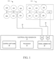
- the signal generator 18 can generate one or more electric signals in the shape of waveforms or trains of pulses.
- the signal generator 18 can be configured to generate an alternating voltage waveform at frequencies in the range from about 50 KHz to about 500 KHz (preferably from about 100 KHz to about 300 KHz) (e.g., the TTFields).
- the voltages are such that the electrical field intensity in tissue to be treated is typically in the range of about 0.1 V/cm to about 10 V/cm.
- One or more outputs 24 of the electrical field generator 12 can be coupled to one or more conductive leads 22 that are attached at one end thereof to the signal generator 18.
- the opposite ends of the conductive leads 22 are connected to the one or more electrode arrays 104 that are activated by the electric signals (e.g., waveforms).
- the conductive leads 22 can comprise standard isolated conductors with a flexible metal shield and can be grounded to prevent the spread of the electrical field generated by the conductive leads 22.
- the one or more outputs 24 can be operated sequentially.
- Output parameters of the signal generator 18 can comprise, for example, an intensity of the field, a frequency of the waves (e.g., treatment frequency), a maximum allowable temperature of the one or more electrode arrays 104, and/or combinations thereof.
- a temperature sensor 107 can be associated with each electrode array 104. Once a temperature sensor measures a temperature above a threshold, current to the electrode array associated with said temperature sensor can be stopped until a second, lower threshold temperature is sensed.
- the output parameters can be set and/or determined by the control software 20 in conjunction with the processor 16. After determining a desired (e.g., optimal) treatment frequency, the control software 20 can cause the processor 16 to send a control signal to the signal generator 18 that causes the signal generator 18 to output the desired treatment frequency to the one or more electrode arrays 104.
- the one or more electrode arrays 104 can be configured in a variety of shapes and positions so as to generate an electrical field of the desired configuration, direction and intensity at a target site (referred to herein also as a "target volume” or a “target region”) so as to focus treatment.
- a target site referred to herein also as a "target volume” or a “target region”
- the one or more electrode arrays 104 can be configured to deliver two perpendicular field directions through the volume of interest.
- transducers are conventionally positioned externally on the patient, the present disclosure recognizes that there are benefits to positioning electrodes within the body of the patient to provide localized electric fields at the site of a tumor.
- TTFields as disclosed herein can beneficially be combined with temozolomide chemotherapy.
- Overall survival now extends to over 60 months in some patients when dexamethasone, which was suspected of interfering with tumor-toxic fields effects, is replaced with celecoxib to control tumorassociated inflammation.
- the transcranial method of delivering tumor-toxic fields has not changed in light of ongoing advances in deep brain stimulation (DBS) and transcranial electric stimulation (TES).
- DBS deep brain stimulation
- TES transcranial electric stimulation
- the resistivity of the skull is an obstacle to placing therapeutic electric field strength (e.g., at least 2 V/cm, at least 3 v/cm, or at least 4 V/cm), into target tumor sites, and variation in skull thickness can cause a difference in TES efficiency across individuals.
- FEM Human head finite element modelling
- 2-4 V/cm can be reliably delivered to tumor sites using minimally-invasive strip or ribbon electrode arrays in conjunction with a distal transcranial electrode pre- or post-resection. It is contemplated that using frequencies at about 200 kHz (e.g., 100-300 kHz), 1-3 orders of magnitude higher than ion channel time constants, can be too high to stimulate axons in situ, thereby avoiding undesirable nervous system side effects.
- field strength can be maintained below levels that cause cell damage.
- the body of a cancer patient has an anatomically well-defined mass composed of contiguous cancer cells, or a shell of cancer cells surrounding a 'necrotic' region in which the cells have died due to being starved of nutrients.
- a tumor can be surgically removed ("resected").
- the volume of the resection can fill with cerebrospinal fluid in the brain or other body fluid in other body regions, which is electrically-conductive and significantly affects an electric field imposed on the region.
- a tumor or resection cavity is surrounded by an anatomically undefined or loosely-defined region containing stray cancer cells, since the extent of stray cancer cells in the vicinity of the tumor is dependent on the tumor cell type, and the highly individualized history, anatomy, immune system, etc. of each patient.
- the region containing stray, non-contiguous cancer cells is referred to herein as a "peritumoral region.”
- a method for treating tumor cells can comprise positioning an implantable device 100 within a patient proximate to a target site (e.g., less than 1 cm from the target site, less than 3 cm of the target site, or within 1-10 cm (or about 1 cm to about 10 cm) of the target site).
- the proximity to the target site can optionally be as close as possible (without inflicting damage to critical tissue) and no further than a spacing at which the field strength is insufficient to kill the tumor cells within the target site (i.e., a maximum effective distance).
- the maximum effective distance can be controlled by a number of factors.
- the field strength can be a function of the power provided to the electrodes, and a maximum power threshold can be limited by a temperature threshold.
- the implantable device 100 can be positioned proximate to the target site to provide sufficient field strength without surpassing a temperature threshold.
- the temperature threshold can be maintained below a temperature threshold at which the patient feels pain (e.g., 41 degrees Celsius) or at a temperature threshold before tissue damage (that can be higher than the latter temperature threshold). It is contemplated that the temperature achieved can be dependent upon the thermal properties of the tissue surrounding the In further aspects, the implantable device 100 can desirably generate sufficient heat (surpassing the temperature threshold at which tissue is damaged) to damage surrounding cells (e.g., ablate surrounding cells).
- the configuration of the electrode array can determine the shape at which the field emanates from the implantable device 100, thereby affecting the maximum effective distance.
- the frequency with which the TTFields are applied to the target site can affect the maximum effective distance.
- the geometry of the surrounding tissue and the properties of said surrounding tissue can affect the maximum distance. Accordingly, computational modeling can be used to determine the ideal position of the implantable device with respect to the target site.
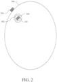
- the implantable device 100 can be positioned in a tumor resection cavity 302, within a peritumoral region 304, or adjacent to a tumor or resection cavity, optionally within the peritumoral region 304 or adjacent to the peritumoral region 304.
- at least two implantable devices 100 can be positioned around the target site (e.g., around the resection cavity, or around a tumor 310).
- two implantable devices 100 can be positioned on opposing sides or generally opposing sides of the target site.
- one or more implantable devices 100 can be inserted directly into the tumor 310 or within the peritumoral region 304.
- a first implantable device and a second implantable device can be positioned within the peritumoral region 304, and the first and second implantable devices can optionally generate TTFields between each other.
- TTField treatment tumor resection can be avoided.
- a single implantable device 100 can be used, whereas for heterogeneous and non-spherical cancer cells, two (or, optionally, more) implantable devices 100 can be used to generate electric fields that overlap the tumor.
- one or more electrodes 200 can be positioned outside of the peritumoral region so that the implantable device and the electrode(s) 200 positioned outside of the peritumoral region can generate TTFields therebetween.
- the implantable device 100 and electrodes 200 can be positioned so that at least a portion of the tumor or peritumoral region lies therebetween (i.e., so that a line extending between the implantable device 100 and the electrodes 200 extends through the tumor or peritumoral region).
- the one or more electrodes 200 can be positioned outside of a cranium 306 (e.g., outside the skin of the patient) or otherwise outside of the body (optionally, outside the skin) of the patient so that at least a portion of the peritumoral region is disposed between the implantable device and the one or more electrodes 200 outside of the peritumoral region.
- a cranium 306 e.g., outside the skin of the patient
- the body optionally, outside the skin
- the peritumoral region can be used to position the electrodes 200 against the head of the patient.
- all of the peritumoral region can be disposed between the implantable device and the one or more electrodes 200.
- the one or more electrodes 200 can be positioned so that the tumor is between the implantable device and the one or more electrodes 200. It is contemplated that different patterns of fields can be generated between electrodes based on the arrangement of the electrodes. As disclosed herein, computational modeling can be used to predict the activation patterns of the combined internal and external electrode arrays that are most effective to deliver efficacious field strength to the target region. In general, the target region can be located between the internal and external activated electrodes. However, change of direction of the applied field can be desirable.
- At least one electrode 200 can be positioned so that an imaginary line between the implantable device and the at least one electrode 200 extends through the target site, and a second pair of electrodes that are skew or orthogonal to the imaginary line between the internal electrodes through the target region to the at least one electrode 200 can be desirable for applying the electric field from a different direction.
- modeling can be performed for generic tumor locations, for example, in different quadrants of the tissue.
- image scans for a given patient can be used to tailor individualized optimal field shaping (e.g., different directional paths of TTFields through the target site) by the various electrodes.
- the one or more electrodes 200 outside of the peritumoral region can comprise one or more transducer arrays that are configured to apply TTFields through a portion of a brain of a patient.
- transducer arrays can be provided as components of an OPTUNE system (NOVOCURE Gmbh) for applying TTFields.
- OPTUNE system NOVOCURE Gmbh
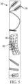
- the implantable device can comprise a strip or ribbon electrode assembly comprising a thin substrate 102 with one or more electrodes 106 coupled thereto (optionally, arranged in an array 104).
- the thin substrate 102 can have a thickness of less than 2 mm, such as for example, a thickness from 0.1 mm to 1 mm.
- Exemplary ribbon electrode assemblies that are suitable for use as disclosed herein include subdural grid or strip electrodes manufactured by AD-TECH Medical Instrument Corporation. It is contemplated that the thin substrate 102 can be flexible for select positioning of the electrodes 106 within the resection cavity 302.
- the tumor resection cavity can be lined with an anti-bacterial mesh or other surgical material 308.
- the anti-bacterial mesh or other surgical material 308 can be that which is used in conventional neurosurgery. In some aspects, the anti-bacterial mesh or other surgical material 308 can have negligible electrical resistance or be designed to minimally interfere with, or enhance, the applied electric field.
- the implantable device 100 can be positioned within the mesh.
- the shape or profile of the implantable device 10 can be bent or otherwise modified to match the contour of the mesh. For example, the implantable device 100 can be pressed against inner surfaces of the mesh 308.
- the implantable device 100 can comprise a single electrode 106.
- the implantable device 100 can comprise a plurality of electrodes 106 that can be arranged in various configurations.
- the plurality of electrodes 106 can comprise a single row of electrodes that are arranged along an axis.
- the plurality of electrodes 106 can be arranged on a rectangular grid and can be spaced from each other in equal or unequal spacing.
- the plurality of electrodes 106 can comprise a plurality or rows of electrodes, with the electrodes within each row being arranged along a respective axis.
- the implantable device 100 can comprise an elongate body 150 and a plurality of electrodes 106 coupled thereto.
- the elongate body 150 can optionally be rigid.
- the elongate body 150 can optionally define at least one cylindrical surface.
- the elongate body can define a cross shape in cross-sections in planes perpendicular to the longitudinal axis.
- the elongate body 150 can comprise a first body portion 160, a second body portion 162, a third body portion 164, and a fourth body portion 166 that converge at the longitudinal axis 170, with the first and second body portions 160, 162 being aligned relative to a first transverse axis 172 that is perpendicular to the longitudinal axis 170, and with the third and fourth body portions 164, 166 being aligned relative to a second transverse axis 174 that is perpendicular to the longitudinal axis and the first transverse axis.
- first and second body portions can have equal or substantially equal dimensions relative to the first transverse axis
- third and fourth body portions can have equal or substantially equal dimensions relative to the second transverse axis
- the dimensions of the first and second body portions relative to the first transverse axis can be equal or substantially equal to the dimensions of the third and fourth body portions relative to the second transverse axis.
- the electrodes for an exemplary implantable device 100 can optionally have uniform dimensions or non-uniform dimensions and can optionally have uniform or non-uniform spacing relative to the longitudinal axis.
- the electrodes can have surface area dimensions ranging from 0.1 mm x 0.1 mm to 1.5mm x 1.15 mm.
- the electrodes can be larger or smaller, depending on the application.
- the electrodes can be spaced by 0.1 mm or less, by between 0.1 and 0.5 mm, by at least 0.5 mm, by 0.5 mm to 1 mm, or more than 1 mm.
- the electrodes 106 can optionally be circular, circular profiles projected onto a cylindrical surface, rectangular, rectangular profiles projected onto a cylindrical surface, cylindrical, or any other suitable shape.
- the implantable device 100 can be a deep brain stimulation (DBS) probe as is known in the art.
- DBS probes in accordance with embodiments disclosed herein can include MEDTRONIC 3387 DBS probes, MEDTRONIC 3389 DBS probes, ABBOT INFINITY probes, BOSTON SCIENTIFIC probes, DIRECT STNACUTE probes, MEDTRONIC-SAPIENS probes, micro-DBS probes, AD-TEC depth, strip, or ribbon ('Grid') electrodes, AD-TEC subdural electrodes, WISE cortical strips, or DBS probes as described in Anderson, DariaNesterovich, et al.
- implantable device 100 can have any selected dimensions or any arrangement or distribution of electrodes that is capable of providing electrical stimulation in the manner disclosed herein.
- the electrodes 106 can comprise platinum-iridium.
- the electrodes can comprise a ceramic.
- ceramics can have a preferable impedance at certain beneficial frequencies (e.g., 50-500 kHz or 100-300 kHz).
- the electrodes 106 can be activated with a selectable amplitude.
- the electrodes disclosed herein can be used to generate TTFields in various combinations so that the direction of the field through the target site can be varied.
- the TTFields can optionally be current- or voltage-controlled. It is contemplated that currentcontrolled TTFields can achieve more fidelity in a desired waveform (e.g., a rectangular shape) as well as more uniform field string over time as fibrous material (e.g., scar tissue) that is electrically resistive forms around the electrode(s).
- a current-driven waveform can keep the current and field constant as the electrical resistance changes.
- TTFields can be generated between different electrodes 106 of the implantable device 100. In further aspects, TTFields can be generated between electrodes 106 of the implantable device 100 and the one or more electrodes 200. In further aspects, TTFields can be generated between electrodes 106 of two different implantable devices 100.
- TTFields can be generated at one or more frequencies from 50-500 kHz, optionally, from 100-300 kHz.
- the field strength through the target areas can be at least 2 V/cm, at least 3 V/cm, at least 4 V/cm, or between 2 V/cm and 4 V/cm.
- the direction of the TTFields can be periodically changed.
- the activated cathodic and anodic electrodes in an array can be changed periodically to achieve the goal of delivering the most effective field (optionally, the highest field strength) to a given tumor/peritumoral target.
- the pattern of activated cathodic and anodic electrodes in an array can be periodically varied to change the direction of the field to optimally deliver the highest field strength to target structures, such as microtubules or organelles, that have different orientations relative to the imposed field due to random cell axis orientations in the target tissues.
- changing the direction of the TTFields can comprise switching the polarities of the electrodes inducing the TTFields.
- a first polarity can be induced between one or more electrodes of the implantable device 100 and the electrode(s) 200 outside the peritumoral region 304 (optionally outside the cranium 308 or otherwise outside of the skin of the patient); and, after a select period, a second polarity, opposite the first polarity, can be induced between the electrode(s) 106 of the implantable device and the electrode(s) 200 outside of the peritumoral region.
- the electrodes between which the field is induced can be changed.
- the field can be induced between at least two electrodes 106 of the implantable device, and, to change direction, the field can be induced between a different combination of electrodes 106 of the implantable device 100.
- the field can be induced between at least two electrodes 106 of the implantable device, and, to change direction, the field can be switched to being induced between at least one electrode 106 of the implantable device 100 and the electrode(s) 200 outside the peritumoral region.
- the field can be induced between a first combination of at least one electrode 106 of the implantable device 100 and the electrode(s) 200, and the change in direction of the field can be caused by changing the electrodes of the implantable device 100 and/or the electrode(s) 200 that are inducing the field.
- the field can be induced between a first combination of at least one electrode 106 of a first implantable device 100 and at least one electrode 106 of a second implantable device 100, and the change in direction of the field can be caused inducing a second combination of at least one electrode 106 of a first implantable device 100 and at least one electrode 106 of a second implantable device 100.
- the change in direction of the electric field before and after each direction change can be between 30 and 90 degrees, or between 45 and 90 degrees, or about 90 degrees.
- electric fields can be generated in directions that are angled at at least 30 degrees with respect to each other, at least 45 degrees with respect to each other, or at least 60 degrees with respect to each other. It is contemplated that a mechanism of action of tumor-killing electric fields (i.e., TTFields) is their effect on polarized cell membrane and/or sub-cellular structures.
- TTFields can provide significant tumoricidal (tumor-killing) effects when the field is aligned with the cell axis during mitosis, and secondarily, when orthogonal to it.
- tumoricidal (tumor-killing) effects of TTFields can be diminished (or even negligible) when at 45 degrees (or about 45 degrees) to the cell axis.
- one orthogonal change of direction per second of the applied field is performed and provides a 20% increase in efficacy (in comparison to no change of direction).
- each change of field direction can reduce the variance of field strength to which polarized cell structures are subjected, thereby increasing the minimum field strength to which they are subjected, leading to desirable results. Further, each change of field direction can reduce the maximum field strength necessary to ensure sufficient field strength is delivered to the target.
- the processor(s) 16 can be configured to control the polarity induction between electrodes.
- the processor(s) can alternate induced polarities between two or more electrodes.
- the processor(s) 16 can be configured to switch the induced polarity between two or more electrodes so that the electrodes operating as electrodes and anodes and cathodes, respectively, can be reversed after a predetermined period.
- the processor(s) can repeatedly reverse the induced polarity.
- the processor(s) can be configured to change which electrodes serve as anode(s) and cathode(s).
- the processor(s) can cause the electrical field generator 12 ( FIG.
- the processor(s) can execute a protocol stored in a memory that causes the processor to effect a sequential change in polarity and/or electrode combinations in accordance with a stored protocol.
- a stored protocol can comprise a predetermined sequence of electrode polarity induction for predetermined durations.
- Such a stored protocol can optionally be customized for generic tumor locations and electrode arrays or for a particular patient given knowledge of tumor location and physical geometry of the patient.
- a random sequence can be preferable for effectivity, whereas for a particular patient for which a clinician has knowledge of tumor location and physical geometry, a tailored sequence and/or arrangement can provide optimal tumoricidal results.
- a single implantable device 100 can be inserted into or proximate to a target area (e.g., a tumor or a tumor resection cavity).
- the single implantable device 100 can comprise an elongate rigid body 150 and a plurality of electrodes 106 spaced longitudinally along the length of the body.
- the single implantable device 100 can be a DBS probe. It is contemplated that generating electrical fields between electrodes spaced farthest apart can generate a broad (optionally, the broadest possible) field coverage (e.g., through the resection cavity and peritumoral region).
- two implantable devices 100 can be inserted into or proximate to (e.g., on opposite sides of) a target area (e.g., a tumor or a tumor resection cavity). In further aspects, it is contemplated that the two implantable device 100 can be positioned within the cavity (e.g., on opposing edges within the resection cavity).
- the two implantable devices 100 can each comprise an elongate rigid body and a plurality of electrodes 106 spaced longitudinally along the length of the body.
- the two implantable devices 100 can be DBS probes. Different electrodes on each probe can be polarized in sequence to induce electrical fields in different directions.
- each of the implantable devices 100 can have inner electrodes 106a and outer electrodes 106b, wherein the inner electrodes are relatively closer to the other implantable device than the outer electrodes.
- TTFields can be generated between respective inner electrodes of each of the two implantable devices to deliver relatively high strength electric fields.
- TTFields can be generated between respective outer electrodes of each of the two implantable devices to deliver more broadly reaching TTFields (i.e., TTFields propagating further from the electrodes).
- ribbon electrode arrays can be placed around the tumor or resection cavity.
- ribbon electrode arrays can provide smaller and more closely packed electrode arrays than traditional cylindrical DBS probes to more precisely deliver the strongest fields either to the tumor or resection cavity or to the peritumoral region.
- the electrodes can be activated sequentially around the tumor resection cavity, for example, to deliver strongest doses to the area orthogonal to the electrode faces while delivering a weaker, but still therapeutic dose from a different direction to the areas adjacent to the electrodes.
- an implantable device 100 as disclosed herein can be configured for removal from within the patient before the skin of the patient grows over a cavity within which the implantable device is received (e.g., within about 3 to 4 weeks).
- the cavity within which the implantable device is received can be formed by a craniectomy or other similar procedure.
- cells from within the patient can be gathered from the implantable device to permit analysis of patient cells that remain on surfaces of the implantable device (e.g., a ribbon or strip electrode as disclosed herein), thereby permitting analysis of tumor cells or cells within the peritumoral region or other target area.
- an implantable device 100 as disclosed herein can be configured to be powered by a battery or other power source positioned external to the patient, thereby providing a long-term implant configuration.
- in situ TTFields with the external array is the ability to steer the electric field across the tumor/peritumoral region by altering the activated electrodes on the external array.
- Another advantage of in situ tumor-treating fields is the ability to precisely control the field in the vicinity of the target tumor/peritumoral region, thereby avoiding or minimizing collateral damage to nearby, healthy, rapidly-dividing cells.
- another advantage is the ability to optimize 1) the static pattern of electrodes at a given point in time, 2) changing field direction in order to impose alignment or orthogonality with cell axes, and 3) changing field direction to attain the largest region of therapeutic dose while minimizing hot spots, which can optionally be characterized by temperature (e.g. 41 degrees Centigrade) to avoid pain and/or by surface current density (such as 30 or 60 microCoulombs per centimeter square) to avoid undesired biochemical reactions at the electrode-tissue interface.
- temperature e.g. 41 degrees Centigrade
- surface current density such as 30 or 60 microCoulombs per centimeter
- the temperature increase caused by the interaction of current flow through electrically resistive tissue can be a limitation to the maximum voltage, current, and power supplied to device 100.
- the implantable device 100 can be used to effect a temperature that kills tissue cells.
- the implantable device 100 can be used for the dual purpose of destroying tumor cells via tumor-killing electric fields as well as killing cells with heat (tissue 'ablation').
- a metric such as the Arrhenius equation can be used in computer simulations to predict the 3-dimensional extent of tumor cell ablation, given parameters of voltage, current, or power supplied to device 100.
- the implantable device can comprise a temperature sensor (e.g., a thermocouple or thermistor).
- a temperature sensor can be positioned proximate to the implantable device for measuring the temperature of the implantable device or the tissue proximate to the implantable device.
- the devices and non-claimed methods disclosed herein can optionally be used to treat glioblastoma or other cancers in the brain.
- the devices and methods disclosed herein can be used to treat cancers or tumor cells in other parts of the body, such as for example, the torso.
- the external arrays disclosed herein can be positioned on the skin of a patient while also being in proximity to a tumor or peritumoral region within the body.
- the implantable devices disclosed herein can comprise a DBS electrode (e.g., a DBS probe) that is positioned within the torso of a patient.
- Electrodes can be positioned on various parts of the body depending on the location of the target site.
- Exemplary target sites outside the brain include the lungs and other internal organs.
- electrodes can be positioned outside portions of the torso for treatment of tumors within the lungs or other internal organs, or any other site within the torso where a tumor is identified.
Landscapes
- Health & Medical Sciences (AREA)
- Life Sciences & Earth Sciences (AREA)
- General Health & Medical Sciences (AREA)
- Animal Behavior & Ethology (AREA)
- Veterinary Medicine (AREA)
- Public Health (AREA)
- Engineering & Computer Science (AREA)
- Biomedical Technology (AREA)
- Nuclear Medicine, Radiotherapy & Molecular Imaging (AREA)
- Radiology & Medical Imaging (AREA)
- Heart & Thoracic Surgery (AREA)
- Neurosurgery (AREA)
- Psychology (AREA)
- Neurology (AREA)
- Cardiology (AREA)
- Hospice & Palliative Care (AREA)
- Oncology (AREA)
- Biophysics (AREA)
- Electrotherapy Devices (AREA)
Claims (13)
- Système, comprenant :un générateur de champ électrique (12) ; etun dispositif implantable (100) en communication électrique avec le générateur de champ (12) et configuré pour être positionné à proximité ou à l'intérieur d'un site cible d'un patient, dans lequel le générateur de champ (12) est configuré pour utiliser le dispositif implantable (100) pour générer des champs électriques à une fréquence d'environ 50 kHz à environ 500 kHz ; caractérisé en ce que :
le générateur de champ (12) est configuré pour changer périodiquement une direction des champs électriques à une fréquence d'un changement de direction orthogonal par seconde. - Système selon la revendication 1, dans lequel le dispositif implantable (100) comprend un substrat mince (102) et au moins une électrode (106) couplée au substrat (102).
- Système selon la revendication 2, dans lequel le dispositif implantable (100) est configuré pour être positionné dans une cavité de résection de tumeur.
- Système selon la revendication 2, comprenant en outre :
au moins une électrode externe (200) en communication électrique avec le générateur de champ (12) et configurée pour être positionnée à l'écart du site cible, dans lequel le générateur de champ (12) est configuré pour générer des champs électriques entre le dispositif implantable (100) et la au moins une électrode externe (200), facultativement, la au moins une électrode externe (200) est configurée pour être positionnée à l'extérieur de la peau du patient de sorte qu'au moins une partie du site cible soit disposée entre le dispositif implantable (100) et la au moins une électrode externe (200). - Système selon la revendication 2, dans lequel la au moins une électrode (106) du dispositif implantable (100) comprend une pluralité d'électrodes (106), la pluralité d'électrodes comprenant au moins des première et seconde électrodes (106), et le générateur de champ (12) est configuré pour changer la direction du champ électrique en induisant une première polarité au niveau de la première électrode (106), puis en induisant la première polarité au niveau de la seconde électrode (106).
- Système selon la revendication 4, dans lequel le générateur de champ (12) est configuré pour changer périodiquement la direction des champs électriques en induisant une première polarité entre au moins une électrode (106) du dispositif implantable (100) et la au moins une électrode externe (200), et en induisant une seconde polarité, opposée à la première polarité, entre la au moins une électrode (106) du dispositif implantable (100) et la au moins une électrode externe (200).
- Système selon la revendication 2, dans lequel la au moins une électrode (106) du dispositif implantable (100) comprend une céramique.
- Système selon la revendication 2, dans lequel le dispositif implantable (100) est configuré pour être positionné dans le cerveau du patient.
- Système selon la revendication 2, dans lequel le générateur de champ (12) est configuré pour générer des champs électriques à travers le site cible qui amènent au moins une partie du site cible à dépasser une température seuil suffisante pour endommager les cellules de la au moins une partie du site cible.
- Système selon la revendication 1, dans lequel le dispositif implantable (100) comprend un corps allongé (150) et une pluralité d'électrodes (106) couplées au corps allongé (150), comprenant facultativement en outre :
au moins une électrode externe (200) en communication électrique avec le générateur de champ (12) et configurée pour être positionnée à l'écart du site cible, dans lequel le générateur de champ (12) est configuré pour générer des champs électriques entre le dispositif implantable (100) et la au moins une électrode externe (200). - Système selon la revendication 10, dans lequel le corps allongé (150) est rigide.
- Système selon la revendication 10, dans lequel la pluralité d'électrodes (106) du dispositif implantable (100) comprennent une céramique.
- Système selon la revendication 1, dans lequel le dispositif implantable (100) est un premier dispositif implantable, et comprenant en outre :
un second dispositif implantable (100), dans lequel le second dispositif implantable (100) comprend au moins une électrode (106), et le générateur de champ (12) est configuré pour générer des champs électriques entre la au moins une électrode (106) du premier dispositif implantable (100) et la au moins une électrode (106) du second dispositif implantable (100).
Applications Claiming Priority (4)
| Application Number | Priority Date | Filing Date | Title |
|---|---|---|---|
| US201962938586P | 2019-11-21 | 2019-11-21 | |
| US202063085658P | 2020-09-30 | 2020-09-30 | |
| EP20816852.6A EP4061477B1 (fr) | 2019-11-21 | 2020-11-19 | Réseaux implantables pour fournir des champs de traitement de tumeurs |
| PCT/US2020/061251 WO2021102120A1 (fr) | 2019-11-21 | 2020-11-19 | Réseaux implantables pour fournir des champs de traitement de tumeurs |
Related Parent Applications (2)
| Application Number | Title | Priority Date | Filing Date |
|---|---|---|---|
| EP20816852.6A Division-Into EP4061477B1 (fr) | 2019-11-21 | 2020-11-19 | Réseaux implantables pour fournir des champs de traitement de tumeurs |
| EP20816852.6A Division EP4061477B1 (fr) | 2019-11-21 | 2020-11-19 | Réseaux implantables pour fournir des champs de traitement de tumeurs |
Publications (3)
| Publication Number | Publication Date |
|---|---|
| EP4129397A1 EP4129397A1 (fr) | 2023-02-08 |
| EP4129397B1 true EP4129397B1 (fr) | 2024-09-25 |
| EP4129397C0 EP4129397C0 (fr) | 2024-09-25 |
Family
ID=73646603
Family Applications (4)
| Application Number | Title | Priority Date | Filing Date |
|---|---|---|---|
| EP22197055.1A Withdrawn EP4134127A1 (fr) | 2019-11-21 | 2020-11-19 | Appareil pour fournir des champs de traitement de tumeur |
| EP22197081.7A Active EP4129397B1 (fr) | 2019-11-21 | 2020-11-19 | Réseaux implantables pour fournir des champs de traitement de tumeur |
| EP20816852.6A Active EP4061477B1 (fr) | 2019-11-21 | 2020-11-19 | Réseaux implantables pour fournir des champs de traitement de tumeurs |
| EP22197121.1A Withdrawn EP4129398A1 (fr) | 2019-11-21 | 2020-11-19 | Réseaux implantables pour fournir des champs de traitement de tumeur |
Family Applications Before (1)
| Application Number | Title | Priority Date | Filing Date |
|---|---|---|---|
| EP22197055.1A Withdrawn EP4134127A1 (fr) | 2019-11-21 | 2020-11-19 | Appareil pour fournir des champs de traitement de tumeur |
Family Applications After (2)
| Application Number | Title | Priority Date | Filing Date |
|---|---|---|---|
| EP20816852.6A Active EP4061477B1 (fr) | 2019-11-21 | 2020-11-19 | Réseaux implantables pour fournir des champs de traitement de tumeurs |
| EP22197121.1A Withdrawn EP4129398A1 (fr) | 2019-11-21 | 2020-11-19 | Réseaux implantables pour fournir des champs de traitement de tumeur |
Country Status (5)
| Country | Link |
|---|---|
| US (1) | US20240299742A1 (fr) |
| EP (4) | EP4134127A1 (fr) |
| JP (1) | JP2023502506A (fr) |
| CN (1) | CN114746145B (fr) |
| WO (1) | WO2021102120A1 (fr) |
Families Citing this family (6)
| Publication number | Priority date | Publication date | Assignee | Title |
|---|---|---|---|---|
| CA3224334A1 (fr) * | 2021-06-30 | 2023-01-05 | Novocure Gmbh | Systeme d'administration de champs de traitement de tumeurs (ttchamps) et d'impedance de mesure |
| CN114225215B (zh) * | 2021-12-31 | 2023-05-05 | 湖南安泰康成生物科技有限公司 | 电极系统 |
| CN115227977B (zh) * | 2022-07-21 | 2024-01-26 | 佛山科学技术学院 | 一种肿瘤电脉冲化学治疗系统 |
| JP2025537414A (ja) * | 2023-02-06 | 2025-11-14 | ノボキュア ゲーエムベーハー | 異方性材料層を備えた移行可能なトランスデューサアレイ |
| CN116650838B (zh) * | 2023-06-08 | 2024-10-18 | 山东大学齐鲁医院 | 一种脑内植入式电场治疗设备 |
| WO2025068877A1 (fr) * | 2023-09-29 | 2025-04-03 | Novocure Gmbh | Système d'ablation par rf à basse fréquence |
Family Cites Families (17)
| Publication number | Priority date | Publication date | Assignee | Title |
|---|---|---|---|---|
| US4016886A (en) * | 1974-11-26 | 1977-04-12 | The United States Of America As Represented By The United States Energy Research And Development Administration | Method for localizing heating in tumor tissue |
| US4346715A (en) * | 1978-07-12 | 1982-08-31 | The United States Of America As Represented By The Administrator Of The National Aeronautics And Space Administration | Hyperthermia heating apparatus |
| DE19758114C2 (de) * | 1997-12-17 | 2001-08-23 | Biotronik Mess & Therapieg | Elektrodenanordnung zur Rückenmarkstimulation |
| US6868289B2 (en) * | 2002-10-02 | 2005-03-15 | Standen Ltd. | Apparatus for treating a tumor or the like and articles incorporating the apparatus for treatment of the tumor |
| JP4750784B2 (ja) * | 2004-04-23 | 2011-08-17 | ノヴォキュアー・リミテッド | 異なる周波数の電界による腫瘍等の治療 |
| US20170050021A1 (en) * | 2004-08-20 | 2017-02-23 | Eric Richard Cosman, SR. | Random pulsed high frequency therapy |
| JP5559460B2 (ja) * | 2004-12-27 | 2014-07-23 | スタンデン・リミテッド | 異なる配向の電界を用いて腫瘍またはその類似物を処理する方法 |
| US7455689B2 (en) * | 2005-08-25 | 2008-11-25 | Edwards Lifesciences Corporation | Four-leaflet stented mitral heart valve |
| DK1933937T3 (en) * | 2005-10-03 | 2015-04-07 | Novocure Ltd | OPTIMIZATION OF THE CHARACTERISTICS OF AN ELECTRIC FIELD FOR ENHANCING FIELD EFFECT ON proliferating cells |
| WO2009134477A1 (fr) * | 2008-04-29 | 2009-11-05 | Medtronic, Inc. | Modification de programme de thérapie |
| WO2014121217A2 (fr) * | 2013-02-01 | 2014-08-07 | The Texas A&M University System | Excitation de fluorescence localisée en imagerie optique du corps entier |
| WO2017201625A1 (fr) * | 2016-05-25 | 2017-11-30 | Samuel Victor Lichtenstein | Système de traitement de tissus non souhaités |
| AU2017289870B2 (en) * | 2016-06-30 | 2021-12-23 | Novocure Gmbh | Arrays for longitudinal delivery of TTFields to a body |
| PL421532A1 (pl) * | 2017-05-08 | 2018-11-19 | Michalczyk Marta | System do leczenia nowotworów wewnątrzczaszkowych z wykorzystaniem implantu, generującego ciągłe, zmienne pole elektryczne oraz ultradźwięki, zasilanego metodą przezskórnego transferu energii |
| US11338135B2 (en) * | 2017-10-23 | 2022-05-24 | Cardiac Pacemakers, Inc. | Medical devices for cancer therapy with electric field shaping elements |
| US12403306B2 (en) * | 2017-10-23 | 2025-09-02 | Cardiac Pacemakers, Inc. | Electric field shaping leads for treatment of cancer |
| WO2020219517A2 (fr) * | 2019-04-23 | 2020-10-29 | Boston Scientific Scimed, Inc. | Stimulation électrique de traitement du cancer avec des électrodes internes et externes |
-
2020
- 2020-11-19 EP EP22197055.1A patent/EP4134127A1/fr not_active Withdrawn
- 2020-11-19 EP EP22197081.7A patent/EP4129397B1/fr active Active
- 2020-11-19 CN CN202080080428.5A patent/CN114746145B/zh active Active
- 2020-11-19 EP EP20816852.6A patent/EP4061477B1/fr active Active
- 2020-11-19 JP JP2022529893A patent/JP2023502506A/ja active Pending
- 2020-11-19 WO PCT/US2020/061251 patent/WO2021102120A1/fr not_active Ceased
- 2020-11-19 EP EP22197121.1A patent/EP4129398A1/fr not_active Withdrawn
- 2020-11-19 US US17/778,319 patent/US20240299742A1/en active Pending
Also Published As
| Publication number | Publication date |
|---|---|
| EP4061477A1 (fr) | 2022-09-28 |
| EP4061477B1 (fr) | 2023-09-06 |
| WO2021102120A1 (fr) | 2021-05-27 |
| EP4134127A1 (fr) | 2023-02-15 |
| CN114746145A (zh) | 2022-07-12 |
| US20240299742A1 (en) | 2024-09-12 |
| EP4129398A1 (fr) | 2023-02-08 |
| EP4061477C0 (fr) | 2023-09-06 |
| EP4129397C0 (fr) | 2024-09-25 |
| EP4129397A1 (fr) | 2023-02-08 |
| JP2023502506A (ja) | 2023-01-24 |
| CN114746145B (zh) | 2025-09-12 |
Similar Documents
| Publication | Publication Date | Title |
|---|---|---|
| EP4129397B1 (fr) | Réseaux implantables pour fournir des champs de traitement de tumeur | |
| US12173280B2 (en) | Methods of reducing adverse effects of non-thermal ablation | |
| US12059197B2 (en) | Blood-brain barrier disruption using reversible or irreversible electroporation | |
| ES2355462T3 (es) | Sistema para la modificación del tejido nervioso. | |
| USRE40279E1 (en) | Method and system for neural tissue modification | |
| US20190022425A1 (en) | Device And Method for Non-Invasive Neuromodulation | |
| US20170056093A1 (en) | Random pulsed high frequency therapy | |
| JP2023543301A (ja) | 腫瘍治療電場を形成するための植込み可能アレイ | |
| KR20180006365A (ko) | 신경전도 확인 및 제한을 위한 시스템 및 디바이스 | |
| US20250000569A1 (en) | Blood-brain barrier disruption using reversible or irreversible electroporation | |
| EP2542298A2 (fr) | Système, dispositif et procédés de traitement de tissu pour parvenir à des effets spécifiques à un tissu | |
| JP2020089723A (ja) | 神経系構造を選択的かつ可逆的に調節して疼痛知覚を抑制する装置及び方法 | |
| US20250228602A1 (en) | Methods of reducing adverse effects of non-thermal ablation | |
| WO2013114156A1 (fr) | Appareil et procédé d'irradiation de tissu biologique | |
| US20240099769A1 (en) | Methods and Systems for Thermal Enhancement of Electroporation | |
| US20240335660A1 (en) | Electrical applicators with non-penetrating electrodes for applying energy to tissue surfaces | |
| HK40080408B (en) | Implantable arrays for providing tumor treating fields | |
| HK40080408A (en) | Implantable arrays for providing tumor treating fields | |
| HK40080867A (en) | Implantable arrays for providing tumor treating fields | |
| HK40081209A (en) | Apparatus for providing tumor treating fields | |
| HK40073711A (en) | Implantable arrays for providing tumor treating fields | |
| HK40073711B (en) | Implantable arrays for providing tumor treating fields | |
| TW202602515A (zh) | 用於腫瘤電場治療之電極貼片 | |
| CN113631113A (zh) | 用于治疗组织的设备和方法 |
Legal Events
| Date | Code | Title | Description |
|---|---|---|---|
| PUAI | Public reference made under article 153(3) epc to a published international application that has entered the european phase |
Free format text: ORIGINAL CODE: 0009012 |
|
| STAA | Information on the status of an ep patent application or granted ep patent |
Free format text: STATUS: REQUEST FOR EXAMINATION WAS MADE |
|
| 17P | Request for examination filed |
Effective date: 20221024 |
|
| AC | Divisional application: reference to earlier application |
Ref document number: 4061477 Country of ref document: EP Kind code of ref document: P |
|
| AK | Designated contracting states |
Kind code of ref document: A1 Designated state(s): AL AT BE BG CH CY CZ DE DK EE ES FI FR GB GR HR HU IE IS IT LI LT LU LV MC MK MT NL NO PL PT RO RS SE SI SK SM TR |
|
| REG | Reference to a national code |
Ref country code: HK Ref legal event code: DE Ref document number: 40080408 Country of ref document: HK |
|
| GRAP | Despatch of communication of intention to grant a patent |
Free format text: ORIGINAL CODE: EPIDOSNIGR1 |
|
| STAA | Information on the status of an ep patent application or granted ep patent |
Free format text: STATUS: GRANT OF PATENT IS INTENDED |
|
| RIC1 | Information provided on ipc code assigned before grant |
Ipc: A61N 1/04 20060101ALN20240701BHEP Ipc: A61N 1/40 20060101ALI20240701BHEP Ipc: A61N 1/05 20060101ALI20240701BHEP Ipc: A61N 1/36 20060101AFI20240701BHEP |
|
| INTG | Intention to grant announced |
Effective date: 20240716 |
|
| GRAS | Grant fee paid |
Free format text: ORIGINAL CODE: EPIDOSNIGR3 |
|
| GRAA | (expected) grant |
Free format text: ORIGINAL CODE: 0009210 |
|
| STAA | Information on the status of an ep patent application or granted ep patent |
Free format text: STATUS: THE PATENT HAS BEEN GRANTED |
|
| AC | Divisional application: reference to earlier application |
Ref document number: 4061477 Country of ref document: EP Kind code of ref document: P |
|
| AK | Designated contracting states |
Kind code of ref document: B1 Designated state(s): AL AT BE BG CH CY CZ DE DK EE ES FI FR GB GR HR HU IE IS IT LI LT LU LV MC MK MT NL NO PL PT RO RS SE SI SK SM TR |
|
| REG | Reference to a national code |
Ref country code: GB Ref legal event code: FG4D |
|
| REG | Reference to a national code |
Ref country code: CH Ref legal event code: EP |
|
| REG | Reference to a national code |
Ref country code: DE Ref legal event code: R096 Ref document number: 602020038543 Country of ref document: DE |
|
| REG | Reference to a national code |
Ref country code: IE Ref legal event code: FG4D |
|
| U01 | Request for unitary effect filed |
Effective date: 20241022 |
|
| U07 | Unitary effect registered |
Designated state(s): AT BE BG DE DK EE FI FR IT LT LU LV MT NL PT RO SE SI Effective date: 20241105 |
|
| PG25 | Lapsed in a contracting state [announced via postgrant information from national office to epo] |
Ref country code: NO Free format text: LAPSE BECAUSE OF FAILURE TO SUBMIT A TRANSLATION OF THE DESCRIPTION OR TO PAY THE FEE WITHIN THE PRESCRIBED TIME-LIMIT Effective date: 20241225 |
|
| PG25 | Lapsed in a contracting state [announced via postgrant information from national office to epo] |
Ref country code: GR Free format text: LAPSE BECAUSE OF FAILURE TO SUBMIT A TRANSLATION OF THE DESCRIPTION OR TO PAY THE FEE WITHIN THE PRESCRIBED TIME-LIMIT Effective date: 20241226 |
|
| PG25 | Lapsed in a contracting state [announced via postgrant information from national office to epo] |
Ref country code: RS Free format text: LAPSE BECAUSE OF FAILURE TO SUBMIT A TRANSLATION OF THE DESCRIPTION OR TO PAY THE FEE WITHIN THE PRESCRIBED TIME-LIMIT Effective date: 20241225 |
|
| U20 | Renewal fee for the european patent with unitary effect paid |
Year of fee payment: 5 Effective date: 20241225 |
|
| PG25 | Lapsed in a contracting state [announced via postgrant information from national office to epo] |
Ref country code: RS Free format text: LAPSE BECAUSE OF FAILURE TO SUBMIT A TRANSLATION OF THE DESCRIPTION OR TO PAY THE FEE WITHIN THE PRESCRIBED TIME-LIMIT Effective date: 20241225 Ref country code: NO Free format text: LAPSE BECAUSE OF FAILURE TO SUBMIT A TRANSLATION OF THE DESCRIPTION OR TO PAY THE FEE WITHIN THE PRESCRIBED TIME-LIMIT Effective date: 20241225 Ref country code: GR Free format text: LAPSE BECAUSE OF FAILURE TO SUBMIT A TRANSLATION OF THE DESCRIPTION OR TO PAY THE FEE WITHIN THE PRESCRIBED TIME-LIMIT Effective date: 20241226 |
|
| PG25 | Lapsed in a contracting state [announced via postgrant information from national office to epo] |
Ref country code: IS Free format text: LAPSE BECAUSE OF FAILURE TO SUBMIT A TRANSLATION OF THE DESCRIPTION OR TO PAY THE FEE WITHIN THE PRESCRIBED TIME-LIMIT Effective date: 20250125 |
|
| PG25 | Lapsed in a contracting state [announced via postgrant information from national office to epo] |
Ref country code: SM Free format text: LAPSE BECAUSE OF FAILURE TO SUBMIT A TRANSLATION OF THE DESCRIPTION OR TO PAY THE FEE WITHIN THE PRESCRIBED TIME-LIMIT Effective date: 20240925 |
|
| PG25 | Lapsed in a contracting state [announced via postgrant information from national office to epo] |
Ref country code: ES Free format text: LAPSE BECAUSE OF FAILURE TO SUBMIT A TRANSLATION OF THE DESCRIPTION OR TO PAY THE FEE WITHIN THE PRESCRIBED TIME-LIMIT Effective date: 20240925 |
|
| PG25 | Lapsed in a contracting state [announced via postgrant information from national office to epo] |
Ref country code: PL Free format text: LAPSE BECAUSE OF FAILURE TO SUBMIT A TRANSLATION OF THE DESCRIPTION OR TO PAY THE FEE WITHIN THE PRESCRIBED TIME-LIMIT Effective date: 20240925 Ref country code: CZ Free format text: LAPSE BECAUSE OF FAILURE TO SUBMIT A TRANSLATION OF THE DESCRIPTION OR TO PAY THE FEE WITHIN THE PRESCRIBED TIME-LIMIT Effective date: 20240925 |
|
| PG25 | Lapsed in a contracting state [announced via postgrant information from national office to epo] |
Ref country code: SK Free format text: LAPSE BECAUSE OF FAILURE TO SUBMIT A TRANSLATION OF THE DESCRIPTION OR TO PAY THE FEE WITHIN THE PRESCRIBED TIME-LIMIT Effective date: 20240925 |
|
| RAP4 | Party data changed (patent owner data changed or rights of a patent transferred) |
Owner name: NOVOCURE GMBH |
|
| U1H | Name or address of the proprietor changed after the registration of the unitary effect |
Owner name: NOVOCURE GMBH; CH |
|
| REG | Reference to a national code |
Ref country code: CH Ref legal event code: PL |
|
| PG25 | Lapsed in a contracting state [announced via postgrant information from national office to epo] |
Ref country code: MC Free format text: LAPSE BECAUSE OF FAILURE TO SUBMIT A TRANSLATION OF THE DESCRIPTION OR TO PAY THE FEE WITHIN THE PRESCRIBED TIME-LIMIT Effective date: 20240925 |
|
| REG | Reference to a national code |
Ref country code: CH Ref legal event code: PL |
|
| PG25 | Lapsed in a contracting state [announced via postgrant information from national office to epo] |
Ref country code: CH Free format text: LAPSE BECAUSE OF NON-PAYMENT OF DUE FEES Effective date: 20241130 |
|
| PLBE | No opposition filed within time limit |
Free format text: ORIGINAL CODE: 0009261 |
|
| STAA | Information on the status of an ep patent application or granted ep patent |
Free format text: STATUS: NO OPPOSITION FILED WITHIN TIME LIMIT |
|
| 26N | No opposition filed |
Effective date: 20250626 |
|
| PG25 | Lapsed in a contracting state [announced via postgrant information from national office to epo] |
Ref country code: IE Free format text: LAPSE BECAUSE OF NON-PAYMENT OF DUE FEES Effective date: 20241119 |
|
| U20 | Renewal fee for the european patent with unitary effect paid |
Year of fee payment: 6 Effective date: 20251126 |
|
| PGFP | Annual fee paid to national office [announced via postgrant information from national office to epo] |
Ref country code: GB Payment date: 20251125 Year of fee payment: 6 |
|
| PG25 | Lapsed in a contracting state [announced via postgrant information from national office to epo] |
Ref country code: HR Free format text: LAPSE BECAUSE OF FAILURE TO SUBMIT A TRANSLATION OF THE DESCRIPTION OR TO PAY THE FEE WITHIN THE PRESCRIBED TIME-LIMIT Effective date: 20240925 |
|
| PG25 | Lapsed in a contracting state [announced via postgrant information from national office to epo] |
Ref country code: HU Free format text: LAPSE BECAUSE OF FAILURE TO SUBMIT A TRANSLATION OF THE DESCRIPTION OR TO PAY THE FEE WITHIN THE PRESCRIBED TIME-LIMIT; INVALID AB INITIO Effective date: 20201119 |