EP4129147B1 - Einspülsystem für waschmittel - Google Patents
Einspülsystem für waschmittel Download PDFInfo
- Publication number
- EP4129147B1 EP4129147B1 EP22183257.9A EP22183257A EP4129147B1 EP 4129147 B1 EP4129147 B1 EP 4129147B1 EP 22183257 A EP22183257 A EP 22183257A EP 4129147 B1 EP4129147 B1 EP 4129147B1
- Authority
- EP
- European Patent Office
- Prior art keywords
- nozzle
- mixer
- compartment
- dispensing system
- water
- Prior art date
- Legal status (The legal status is an assumption and is not a legal conclusion. Google has not performed a legal analysis and makes no representation as to the accuracy of the status listed.)
- Active
Links
Images



Classifications
-
- D—TEXTILES; PAPER
- D06—TREATMENT OF TEXTILES OR THE LIKE; LAUNDERING; FLEXIBLE MATERIALS NOT OTHERWISE PROVIDED FOR
- D06F—LAUNDERING, DRYING, IRONING, PRESSING OR FOLDING TEXTILE ARTICLES
- D06F39/00—Details of washing machines not specific to a single type of machines covered by groups D06F9/00 - D06F27/00
- D06F39/02—Devices for adding soap or other washing agents
Definitions
- the present invention relates to a dispensing system for a water-conducting household appliance, having a receiving space for receiving a detergent, having a mixing space and having a water inlet, wherein the receiving space is designed to dispense a detergent into the mixing space. Furthermore, the present invention relates to a household appliance with such a dispensing system.
- a detergent or detergent tablet is mixed with water.
- Circulation pumps are usually used to bring a quantity of water let into a household appliance into contact with the detergent, for example in powder form, several times and thus dissolve it.
- Such components increase the number of components required and thus the assembly effort of the household appliance.
- nozzles are known that convey the detergent directly into the working area of the household appliance, such as a laundry drum.
- US 2017 327 991 A1 discloses a washing machine with a dispensing system that has a receiving chamber for a detergent and a mixing chamber.
- a mixing nozzle that can be connected to a water inlet is arranged in the mixing chamber.
- US 2012 246 836 A1 also discloses a washing machine with a flushing system that has a receiving space for a detergent.
- the detergent is flushed out there by a partial flow of flushed water and mixes with the remaining flushing water flow in a flushing channel.
- a washing machine which serves in particular as a laundry treatment device for washing and/or drying laundry. It has a treatment tank and a water supply line, whereby water is fed into the treatment tank via the water supply line.
- the water supply line comprises a venturi pump, whereby a suction side of the venturi pump is connected to a condensate tank.
- condensate temporarily stored in the condensate tank can be sucked in and fed into the treatment tank together with the fresh water.
- Such systems have insufficient washing performance and therefore require a longer period of time to completely dissolve the detergent and its components, such as enzymes and surfactants.
- the invention also relates to a dispensing system, in particular for a water-conducting household appliance, comprising a receiving space for receiving a detergent.
- the detergent can be in a powder form, in a liquid form or in a compressed form, such as a tab shape, or be positioned in the recording space.
- the household appliance can be designed, for example, as a laundry care appliance or as a dishwasher.
- the laundry care appliance can be implemented as a washing machine or as a washer-dryer.
- a household appliance can be a stationary or a mobile or transportable electrical device.
- the dispensing system is not limited to household appliances and can generally be set up for dissolving or mixing liquids with detergents.
- a mixing chamber and a water inlet are provided.
- the receiving chamber is designed to deliver a detergent into the mixing chamber.
- At least one mixing nozzle that can be connected to the water inlet and a suction nozzle downstream of the mixing nozzle are arranged in the mixing chamber.
- the mixing nozzle is designed to mix the detergent with a quantity of water taken from the water inlet.
- the suction nozzle is designed to convey the detergent mixed with the quantity of water out of the mixing chamber.
- the inventive dispensing system means that a circulation pump with corresponding pipes can be dispensed with, while at the same time the washing performance increases, since the detergent is optimally mixed with the water or dissolved in the water by the mixing nozzle in the mixing chamber.
- the mixing chamber can be part of a dispensing bowl of the household appliance or can be arranged away from the dispensing bowl.
- the suction nozzle can act as a passive radiation pump that is driven by the water pressure.
- the suction nozzle transports the prepared lye from the mixing chamber. This measure can reduce the assembly effort for the household appliance. In particular, the number of required electrical components with corresponding control components can be eliminated.
- the amount of water fed into the mixing chamber can, for example, be part of the total amount of water used for cleaning.
- the amount of water can, for example, be controlled via cross-sections of a Y-piece and can be, for example, 500 ml to 2000 ml.
- the mixing nozzle can divert part of the amount of water to mix the detergent. Another part of the amount of water can pass into the suction nozzle to serve as a drive medium. Mechanical work can thus be carried out in the form of mixing water with the detergent.
- the term downstream may mean that the suction nozzle is arranged downstream of the mixing nozzle in a flow direction of the water. This refers here to a position of the induction system in an operating position. Furthermore, the water can flow from an upstream side of the induction system to a downstream side of the induction system in a main flow direction.
- the water inlet is divided by a flow divider into a first partial flow and a second partial flow, the first partial flow having a larger volume flow than the second partial flow.
- the second partial flow flows into the at least one mixing nozzle and then into the intake nozzle.
- the flow divider can be, for example, a T-piece, a Y-piece and the like.
- a predefined volume flow is set based on the ratio of the cross sections of the flow divider and/or the lines to the mixing chamber.
- a control valve can be used to control the volume flow.
- a volume flow directed into the at least one mixing nozzle can be controlled by a valve. This measure enables targeted control of the mixing of the detergent.
- the time at which the lye is prepared can also be set precisely.
- the dispensing system can be operated in bursts.
- the dispensing system can form a control loop for optimal concentration of the prepared lye. Excess lye can, for example, enter the lye container via an opening or an overflow.
- the suction nozzle is designed as a Venturi nozzle.
- the Venturi nozzle has an internal drive nozzle and a suction section surrounding the drive nozzle on the circumference with an axially arranged suction opening.
- the suction section has an outlet opening at an end opposite the suction opening.
- the suction section surrounding the drive nozzle on the circumference has flow surfaces that extend in the direction of the drive nozzle and/or in the direction of the mixing chamber.
- the flow surfaces can interact with the amount of water sucked in or the amount of water mixed and can thus be set in rotation.
- the suction section or the entire suction nozzle is mounted so that it can rotate along the direction of flow.
- the additional rotation of the suction section and the flow surfaces can generate additional turbulence in the lye in the mixing chamber, so that the mixing of the detergent with the amount of water is optimized.
- this measure does not require any electronic aids and can operate completely passively.
- At least one recirculation opening is arranged in the suction section between the suction opening and the outlet opening.
- the recirculation opening allows a portion of the lye to flow out of the suction section into the mixing chamber again. This generates additional mechanical work for mixing the detergent with the amount of water.
- the swirling of the detergent with the water can be particularly efficient if the mixing chamber is designed to be essentially rotationally symmetrical.
- the mixing nozzle is designed as a pipe section with a large number of nozzle openings that runs through the mixing chamber in some areas.
- a mixing nozzle in a mixing chamber that is designed to be essentially rotationally symmetrical, can induce targeted turbulence patterns that cause the detergent to mix with the amount of water.
- the detergent can be mixed with the amount of water on the circumference of the mixing nozzle.
- the mixing nozzle is designed as at least one channel which runs along at least one wall of the mixing chamber.
- the at least one channel has a plurality of nozzle openings which are directed into the mixing chamber. This measure enables the mixing nozzle to act on the mixture of the detergent and the amount of water from one or more sides.
- advantageous mixing of the detergent with the amount of water can be achieved in rectangular or square-shaped mixing chambers.
- the mixing nozzle can achieve a particularly efficient mixing of the detergent and the amount of water if the at least one channel runs along a transverse direction and/or longitudinal direction along at least one wall of the mixing chamber.
- the channel can have an L-shape, a U-shape, an I-shape and the like.
- the channel can extend along rectangular or round or rounded walls and can thus be integrated into the mixing chamber in a particularly flexible manner.
- two mixing nozzles are arranged on two opposite walls of the mixing chamber.
- the nozzle openings of the mixing nozzles are essentially directed towards each other. This measure allows the water quantity to be mixed with the water quantity from two opposite sides. This creates a highly turbulent flow in the mixing chamber, which enables the detergent to be mixed with the water quantity particularly quickly.
- the mixing of the water quantity with the detergent can be improved if the nozzle openings of the mixing nozzle have an exit angle.
- the exit angle of the nozzle openings is designed to create local turbulence and/or to generate a rotary swirl of the liquid in the mixing chamber. The additional induced flow or the additional induced swirl enables the detergent to dissolve in the water even at low water temperatures.
- the escape of water vapor from the working chamber into the receiving chamber or from the household appliance can be prevented if the mixing chamber is designed as a siphon for the receiving chamber.
- a heating device and/or at least one sensor are arranged in the mixing chamber.
- the at least one sensor and/or the heating device are electrically coupled to a control unit.
- the use of a heating element can reduce the time for mixing the detergent with the amount of water.
- the control unit can set a specific water temperature or lye temperature in the mixing chamber, whereby specific active ingredients of the detergent are activated.
- the sensor can be used to measure the temperature and/or the detergent concentration of the water. This can be done, for example, in the form of an electrical conductivity measurement. This measure can be used to provide a control loop with the control unit, which implements a dynamic adjustment of the detergent concentration and the lye temperature.
- the heater or heating element in conjunction with the dispensing system, can dissolve and activate enzyme surfactants and other additives in the detergent more efficiently without damaging them.
- enzymes can be dissolved out of the detergent at low temperatures of less than 20°C and transported to the work area.
- Surfactants in the detergent can be dissolved out at temperatures in the range of 20°C - 40°C and bleach at temperatures above 40°C.
- a method can be provided in which a gradual pre-dissolution of the detergent takes place in the mixing area.
- a household appliance is provided.
- the household appliance can preferably be a water-conducting household appliance for treating laundry or dishes.
- the household appliance has a rinsing system according to the invention
- a receiving space of the dispensing system is arranged in an upper section of the household appliance.
- the mixing space is preferably arranged below the receiving space.
- the mixing space is directly adjacent to the receiving space or indirectly connected to the receiving space via at least one hose. This measure makes it possible to create a modified dispensing bowl with a receiving space and a directly adjacent mixing space.
- the mixing chamber can be spaced apart from the receiving chamber, with a technically simple connecting hose being provided as a fluid-carrying connection to ensure that the detergent is transported into the mixing chamber.
- the mixing chamber can also function as a siphon for the receiving chamber and prevent the formation of condensate in the receiving chamber.
- the household appliance has a working chamber.
- An outlet opening of a suction nozzle of the dispensing system preferably opens directly or indirectly into the working chamber. This allows the suction nozzle to convey the amount of water mixed with the detergent directly into the working chamber. This eliminates the need to use a circulation pump in the household appliance.
- the water supply of the rinsing system is divided by a flow divider into a first partial flow and a second partial flow.
- the first partial flow flows into the working chamber of the household appliance. This measure enables the second partial flow to provide a quantity of water that is mixed with the detergent to form a lye.
- the lye is then added to the first partial flow in the working chamber continuously or in pulses or in predefined steps.
- Fig. 1 shows a front view of a rotary selector device 1 according to the invention, which is arranged on the outer surface of a household appliance according to the invention, in the form of a washing machine 2.
- the rotary selector device 1 comprises a rotary body
- Fig. 1 shows a cross section of a dispensing system 1 according to a first embodiment.
- the dispensing system 1 has a receiving space 2 for receiving a detergent. Furthermore, a mixing space 4 is provided.
- the receiving chamber 2 is arranged at a distance from the mixing chamber 4.
- a connecting hose 6 enables the transport of a detergent from the receiving chamber 2 into the mixing chamber 4.
- a water inlet 8 opens into the mixing chamber 4.
- the water inlet 8 is controlled in the embodiment shown via a valve 10.
- a mixing nozzle 12 connected to the water inlet 8 and a suction nozzle 14 downstream of the mixing nozzle 12 are arranged in the mixing chamber 4.
- the Fig. 4E illustrates the detailed structure of the mixing chamber 4 with the mixing nozzle 12 and the suction nozzle 14.
- the mixing nozzle 12 is designed as a pipe section 15 with a plurality of nozzle openings 16 that runs partially through the mixing chamber 4.
- the nozzle openings 16 are directed radially away from the pipe section 15 and generate local turbulence or
- the suction nozzle 14 downstream of the mixing nozzle 12 has a suction section 18 arranged on the circumference with recirculation openings 20.
- the recirculation openings 20 can be used to achieve additional turbulence and mixing of the water quantity let into the mixing chamber 4.
- the arrows illustrate the turbulence, the suction direction and the flow direction of the water quantity.
- the mixing nozzle 12 is designed to mix the detergent with a quantity of water taken from the water inlet 8 and the suction nozzle 14 is designed to convey the detergent mixed with the quantity of water out of the mixing chamber 4.
- the escape of water vapor from a working chamber 110 downstream of the mixing chamber 4 into the receiving chamber 2 or from a household appliance 100 can be prevented because the mixing chamber 4 acts as a siphon for the receiving chamber 2.
- a heating device 22 and a sensor 24 are arranged in the mixing chamber 4.
- the sensor 24 and the heating device 22 are electrically coupled to a control unit 26.
- the use of the heating element 22 accelerates the mixing process of the detergent with the amount of water and also enables a selective dissolution of components of the detergent with the amount of water in the mixing chamber 4.
- the temperature and/or the detergent concentration of the water can be measured using the sensor 24. This can be done, for example, in the form of an electrical Conductivity measurement can be carried out. This measure makes it possible to provide a control loop with the control unit 26, by means of which a dynamic adjustment of the detergent concentration and the lye temperature is implemented.
- FIG. 2 is a cross-section of the induction system 1 from Fig. 1 in a household appliance 100 according to a first embodiment.
- the household appliance 100 is designed, for example, as a washing machine or as a washer-dryer.
- the receiving space 2 of the dispensing system 1 is arranged in an upper section of the household appliance 100.
- the mixing space 4 is connected to the receiving space 2 via the connecting hose 6.
- the water inlet 8 is divided by a flow divider (not shown) into a first partial flow W1 and a second partial flow W2.
- the first partial flow W1 has a larger volume flow than the second partial flow W2.
- the second partial flow W2 flows into the at least one mixing nozzle 12 of the mixing chamber 4.
- the first partial flow W1 flows directly into the working chamber 110 of the household appliance 100, which is designed as a laundry drum.
- the Fig. 3 shows a cross section of a household appliance 100 with a rinsing system 1 according to a second embodiment.
- the mixing chamber 4 is arranged directly adjacent to the receiving chamber 2.
- the mixing chamber 4 can be designed integrally with the receiving chamber 2.
- a dispensing bowl in the lower part can be designed to be enlarged in order to be able to hold, for example, 500 - 1000 ml, which is fed into the mixing chamber 4 as a quantity of water.
- the suction nozzle 14 is designed as a Venturi nozzle.
- the Venturi nozzle has an internal drive nozzle 17 and a suction section 18 surrounding the drive nozzle 17 on the circumference with an axially arranged suction opening 19 (see. Fig. 4E ).
- the suction section 18 has an outlet opening 21 at an end opposite the suction opening 19.
- the mixing of the water quantity with the detergent can be improved if the nozzle openings 16 of the mixing nozzle 12 have an exit angle.
- the exit angle of the nozzle openings 16 is designed to generate a local turbulence and/or a rotary swirl of the liquid in the mixing chamber 4.
- the additional induced flow or the additional induced swirl enables the detergent to dissolve in the water quantity even at low water temperatures.
- the mixing nozzle 12 is rotatably mounted so that the induced rotary swirl leads to a rotation of the mixing nozzle 12. This converts the flow from the nozzle openings 16 into a mechanical rotary movement of the mixing nozzle 12.
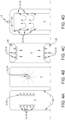
- the Fig. 4 shows top views of a mixing chamber 4 with differently designed mixing nozzles 12.
- the nozzle openings 16 are arranged along two opposite walls 28 of the mixing chamber 4.
- the nozzle openings 16 of the mixing nozzle 12 or the mixing nozzles 12 are positioned on two opposite walls 18 of the mixing chamber 4 and point into the mixing chamber 4.
- the mixing nozzles 12 are designed as channels which run along at least one wall 28 of the mixing chamber 4.
- the corresponding channel runs along several walls 28 and is U-shaped.
- Fig. 4B is a top view of the Fig. 4E illustrated arrangement of the mixing nozzle 12 and suction nozzle 14.
Landscapes
- Engineering & Computer Science (AREA)
- Textile Engineering (AREA)
- Detail Structures Of Washing Machines And Dryers (AREA)
- Cleaning By Liquid Or Steam (AREA)
- Washing And Drying Of Tableware (AREA)
Description
- Die vorliegende Erfindung betrifft ein Einspülsystem, für ein wasserführendes Haushaltsgerät, aufweisend einen Aufnahmeraum zum Aufnehmen eines Waschmittels, aufweisend einen Mischraum und aufweisend einen Wasserzulauf, wobei der Aufnahmeraum dazu eingerichtet ist, ein Waschmittel in den Mischraum abzugeben. Des Weiteren betrifft die vorliegende Erfindung ein Haushalsgerät mit einem derartigen Einspülsystem.
- Für die Behandlung von Wäsche oder zum Säubern von Geschirr wird ein Waschmittel oder ein Waschmittel-Tab mit Wasser vermischt. Üblicherweise werden Umwälzpumpen eingesetzt, um eine in ein Haushaltsgerät hineingelassene Wassermenge mehrmals mit dem Waschmittel, beispielsweise in Pulverform, in Kontakt zu bringen und dieses somit aufzulösen. Derartige Komponenten erhöhen die erforderliche Anzahl von Bauteilen und damit den Montageaufwand des Haushaltsgeräts. Darüber hinaus sind Düsen bekannt, die das Waschmittel direkt in den Arbeitsraum des Haushaltsgeräts, wie beispielsweise eine Wäschetrommel, befördern.
- Druckschrift
US 2017 327 991 A1 offenbart eine Waschmaschine mit einem Einspülsystem, das einen Aufnahmeraum für ein Waschmittel und einen Mischraum aufweist. In dem Mischraum ist eine mit einem Wasserzulauf verbindbare Mischdüse angeordnet. - Druckschrift
US 2012 246 836 A1 offenbart ebenfalls eine Waschmaschine mit einem Einspülsystem, das einen Aufnahmeraum für ein Waschmittel aufweist. Das Waschmittel wird dort von einem Teilstrom eingespülten Wassers ausgespült und vermischt sich in einem Einspürlkanal mit dem restlichen Wasser-Einspülstrom. - Druckschrift
EP 2 199 451 A2 schließlich zeigt eine Waschmaschine, das insbesondere als Waeschebehandlungsgeraet zum Waschen und/oder Trocknen von Wäsche dient. Es weist einen Behandlungsbehaelter und einen Wasserzufuhrstrang auf, wobei über den Wasserzufuhrstrang Wasser in den Behandlungsbehälter geführt wird. Dabei umfasst der Wasserzufuhrstrang eine Venturipumpe, wobei eine Saugseite der Venturipumpe mit einem Kondenswasserbehälter verbunden ist. Beim Zuführen von Frischwasser über den Wasserzufuhrstrang kann dadurch in dem Kondenswasserbehälter voruebergehend gespeichertes Kondenswasser angesaugt werden und zusammen mit dem Frischwasser in den Behandlungsbehälter geführt werden. - Derartige Systeme weisen eine unzureichende Waschperformance auf und erfordern somit eine längere Zeitspanne, um das Waschmittel und seine Bestandteile, wie beispielsweise Enzyme und Tenside, vollständig aufzulösen.
- Es ist die Aufgabe der vorliegenden Erfindung, die Nachteile aus dem Stand der Technik zu eliminieren und ein Einspülsystem zu schaffen, welches eine effizientere und schnellere Vermischung von Leitungswasser mit einem Waschmittel ermöglicht.
- Gelöst wird dieses Problem mit einem Einspülsystem mit den Merkmalen des Anspruchs 1 und mit einem Haushaltsgerät mit den Merkmalen des Anspruch 14.
- Die Erfindung betrifft auch ein Einspülsystem, insbesondere für ein wasserführendes Haushaltsgerät, aufweisend einen Aufnahmeraum zum Aufnehmen eines Waschmittels. Das Waschmittel kann in einer Pulverform, in einer flüssigen Form oder in einer komprimierten Form, wie beispielsweise einer Tab-Form, vorliegen bzw. in dem Aufnahmeraum positioniert werden.
- Das Haushaltsgerät kann beispielsweise als ein Wäschepflegegerät oder als eine Geschirrspülmaschine ausgestaltet sein. Dabei kann das Wäschepflegegerät als eine Waschmaschine oder als ein Waschtrockner realisiert sein. Ein Haushaltsgerät kann in diesem Zusammenhang ein stationäres oder ein mobiles bzw. transportierbares elektrisches Gerät sein. Das Einspülsystem ist jedoch nicht auf Haushaltsgeräte beschränkt und kann generell für das Lösen bzw. Vermischen von Flüssigkeiten mit Waschmitteln eingerichtet sein.
- Des Weiteren sind ein Mischraum und ein Wasserzulauf vorgesehen. Der Aufnahmeraum ist dazu eingerichtet, ein Waschmittel in den Mischraum abzugeben. In dem Mischraum sind zumindest eine mit dem Wasserzulauf verbindbare Mischdüse und eine der Mischdüse nachgeschaltete Ansaugdüse angeordnet. Die Mischdüse ist dazu eingerichtet, das Waschmittel mit einer dem Wasserzulauf entnommener Wassermenge zu vermischen. Die Ansaugdüse ist dazu eingerichtet, das mit der Wassermenge vermischte Waschmittel aus dem Mischraum zu fördern.
- Durch das erfindungsgemäße Einspülsystem kann eine Umwälzpumpe mit entsprechenden Rohrleitungen entfallen, wobei die Waschperformance gleichzeitig steigt, da das Waschmittel durch die Mischdüse im Mischraum optimale mit der Wassermenge vermischt wird bzw. in der Wassermenge gelöst wird. Der Mischraum kann hierbei ein Teil einer Einspülschale des Haushaltsgeräts sein oder aus der Einspülschale ausgelagert angeordnet sein.
- Somit kann das Waschmittel im Vorfeld zu einer Lauge aufgelöst bzw. vorbereitet und anschließend in den Arbeitsraum, wie beispielsweise eine Wäschetrommel, gefördert werden. Die Ansaugdüse kann hierbei als eine passive Strahlungspumpe fungieren, die durch den Wasserdruck angetrieben wird. Die Ansaugdüse transportiert insbesondere die vorbereitete Lauge aus dem Mischraum. Durch diese Maßnahme kann der Montageaufwand des Haushaltsgeräts reduziert werden. Insbesondere kann die Anzahl der erforderlichen elektrischen Komponenten mit entsprechenden Ansteuerungskomponenten entfallen.
- Die in den Mischraum hineingeleitete Wassermenge kann beispielsweise ein Teil einer zum Reinigen verwendeten Gesamtwassermenge sein. Die Wassermenge kann beispielsweise über Querschnitte eines Y-Stücks gesteuert werden und beispielsweise 500 ml bis 2000 ml betragen. Die Mischdüse kann einen Teil der Wassermenge zur Vermischung des Waschmittels ablenken. Ein weiterer Teil der Wassermenge kann weiter in die Ansaugdüse gelangen, um dieser als Antriebsmittel zu dienen. Somit kann mechanische Arbeit in Form eines Vermischens von Wasser mit dem Waschmittel verrichtet werden.
- Der Begriff nachgeschaltet kann bedeuten, die Ansaugdüse in einer Strömungsrichtung des Wassers stromabwärts der Mischdüse angeordnet ist. Dies bezieht sich hierbei auf eine Stellung des Einspülsystems in einer Betriebsposition. Ferner kann das Wasser von einer stromaufwärtigen Seite des Einspülsystems zu einer stromabwärtigen Seite des Einspülsystems in einer Hauptströmungsrichtung strömen.
- Gemäß einem Ausführungsbeispiel ist der Wasserzulauf durch einen Strömungsteiler in einen ersten Teilstrom und einen zweiten Teilstrom geteilt, wobei der erste Teilstrom einen gegenüber dem zweiten Teilstrom größeren Volumenstrom aufweist. Der zweite Teilstrom mündet in der mindestens einen Mischdüse und anschließend in der Ansaugdüse. Durch diese Maßnahme kann ein selbstregulierendes System bzw. mit einer minimalen Anzahl an elektronischen Komponenten bereitgestellt werden. Der Strömungsteiler kann beispielsweise ein T-Stück, ein Y-Stück und dergleichen sein. Dabei wird anhand des Verhältnisses der Querschnitte des Strömungsteilers und/oder der Leitungen zum Mischraum ein vordefinierter Volumenstrom eingestellt. Alternativ kann ein Regelventil zur Steuerung des Volumenstroms eingesetzt werden.
- Nach einer weiteren Ausführungsform ist ein in die mindestens eine Mischdüse gerichteter Volumenstrom durch ein Ventil steuerbar. Durch diese Maßnahme ist eine gezielte Steuerung der Vermischung des Waschmittels möglich. Dabei kann auch der Zeitpunkt der Vorbereitung der Lauge präzise eingestellt werden. Darüber hinaus kann eine stoßweise Arbeitsweise des Einspülsystems umgesetzt werden. Insbesondere in Kombination mit einer Sensorik kann das Einspülsystem eine Regelschleife für eine optimale Konzentration der vorbereiteten Lauge ausbilden. Eine überschüssige Lauge kann beispielsweise über eine Öffnung oder einen Überlauf in den Laugenbehälter gelangen.
- Gemäß einem weiteren Ausführungsbeispiel ist die Ansaugdüse als eine Venturidüse ausgestaltet. Die Venturidüse weist eine innenliegende Treibdüse und einen die Treibdüse umfangsseitig umgebenden Saugabschnitt mit einer axial angeordneten Ansaugöffnung auf. Der Saugabschnitt weist an einem der Ansaugöffnung entgegengesetzt angeordneten Ende eine Auslassöffnung auf. Durch eine Querschnittsverringerung an der innenliegenden Treibdüse kann lokal eine höhere Strömungsgeschwindigkeit erzeugt werden. Die erhöhte Strömungsgeschwindigkeit verursacht dabei einen Unterdruck, welcher umfangsseitig im Bereich des Saugabschnitts entsteht. Somit kann die Venturidüse als eine Art von Strahlpumpe fungieren. Eine derartige Ansaugdüse weist in ihrer einfachsten Ausgestaltung keinerlei bewegliche Komponenten und ist besonders kosteneffizient herstellbar. Insbesondere kann das Bereitstellen von elektrisch angetriebenen UmwälzPumpen entfallen.
- Bei einer Ausgestaltung der Ansaugdüse weist der die Treibdüse umfangsseitig umgebenden Saugabschnitt Strömungsflächen auf, die sich in Richtung der Treibdüse und/oder in Richtung des Mischraums erstrecken. Die Strömungsflächen können mit der angesaugten Wassermenge oder der vermischten Wassermenge interagieren und somit in Rotation versetzt werden. Der Saugabschnitt oder die gesamte Ansaugdüse sind hierfür entlang der Strömungsrichtung drehbar gelagert. Durch die zusätzliche Rotation des Saugabschnitts und der Strömungsflächen kann eine zusätzliche Verwirbelung der Lauge im Mischraum erzeugt werden, sodass die Vermischung des Waschmittels mit der Wassermenge optimiert wird. Diese Maßnahme erfordert gleichzeitig keinerlei elektronische Hilfsmittel und kann vollständig passiv agieren.
- Nach einer weiteren Ausführungsform ist mindestens eine Rezirkulationsöffnung in dem Saugabschnitt zwischen der Ansaugöffnung und der Auslassöffnung angeordnet. Die Rezirkulationsöffnung ermöglicht ein erneutes Hinausströmen eines Teils der Lauge aus dem Saugabschnitt in den Mischraum. Somit wird eine zusätzliche mechanische Arbeit zur Vermischung des Waschmittels mit der Wassermenge erzeugt.
- Die Verwirbelung des Waschmittels mit der Wassermenge kann besonders effizient erfolgen, wenn der Mischraum im Wesentlichen rotationssymmetrisch ausgestaltet ist.
- Gemäß einem weiteren Ausführungsbeispiel ist die Mischdüse als ein bereichsweise durch den Mischraum verlaufender Rohrabschnitt mit einer Vielzahl von Düsenöffnungen ausgestaltet. Insbesondere bei einem im Wesentlichen rotationssymmetrisch ausgestalteten Mischraum können durch eine derartige Mischdüse gezielte Turbulenzmuster induziert werden, die eine Vermischung des Waschmittels mit der Wassermenge verursachen. Insbesondere kann eine Durchmischung des Waschmittels mit der Wassermenge umfangsseitig der Mischdüse erfolgen.
- Nach einer weiteren Ausführungsform ist die Mischdüse als mindestens ein Kanal ausgestaltet, welcher entlang zumindest einer Wandung des Mischraums verläuft. Der mindestens eine Kanal weist eine Vielzahl von Düsenöffnungen auf, welche in den Mischraum hineingerichtet sind. Durch diese Maßnahme kann die Mischdüse von einer oder von mehreren Seiten auf das Gemisch aus dem Waschmittel und der Wassermenge einwirken. Insbesondere kann bei rechteckig oder quadratisch geformten Mischräumen eine vorteilhafte Vermischung des Waschmittels mit der Wassermenge erzielt werden.
- Die Mischdüse kann besonders effizient eine Vermischung des Waschmittels und der Wassermenge erzielen, wenn der mindestens eine Kanal sich entlang einer Querrichtung und/oder Längsrichtung entlang zumindest einer Wandung des Mischraums verläuft. Dabei kann der Kanal eine L-Form, eine U-Form eine I-Form und dergleichen aufweisen. Insbesondere kann der Kanal sich entlang von rechteckigen oder runden bzw. abgerundeten Wandungen erstrecken und somit besonders flexibel in den Mischraum integrierbar sein.
- Gemäß einem weiteren Ausführungsbeispiel sind zwei Mischdüsen an zwei gegenüberliegenden Wandungen des Mischraums angeordnet. Die Düsenöffnungen der Mischdüsen im Wesentlichen auf einander gerichtet sind. Durch diese Maßnahme kann die Wassermenge von zwei gegenüberliegenden Seiten mit der Wassermenge vermischt werden. Hierbei wird eine hochturbulente Strömung im Mischraum erzeugt, die eine besonders schnelle Vermischung des Waschmittels mit der Wassermenge ermöglicht.
- Die Vermischung der Wassermenge mit dem Waschmittel kann verbessert werden, wenn die Düsenöffnungen der Mischdüse einen Austrittswinkel aufweisen. Vorzugsweise ist der Austrittswinkel der Düsenöffnungen dazu eingerichtet, eine lokale Verwirbelung und/oder einen rotatorischen Drall der Flüssigkeit in dem Mischraum zu erzeugen. Die zusätzliche induzierte Strömung oder der zusätzlich induzierte Drall ermöglicht das Lösen des Waschmittels in der Wassermenge auch bei niedrigen Wassertemperaturen.
- Der Austritt von Wasserdampf aus dem Arbeitsraum in den Aufnahmeraum oder aus dem Haushaltsgerät kann unterbunden werden, wenn der Mischraum als ein Siphon für den Aufnahmeraum ausgestaltet ist.
- Nach einer weiteren Ausführungsform sind in dem Mischraum eine Heizvorrichtung und/oder zumindest ein Sensor angeordnet. Vorzugsweise sind der mindestens eine Sensor und/oder die Heizvorrichtung elektrisch mit einem Steuergerät gekoppelt. Der Einsatz eines Heizelements kann die Zeit zum Vermischen des Waschmittels mit der Wassermenge senken. Darüber hinaus kann das Steuergerät eine gezielte Wassertemperatur bzw. Laugentemperatur im Mischraum einstellen, wodurch gezielte Wirkstoffe des Waschmittels aktiviert werden.
- Mit Hilfe des Sensors kann die Temperatur und/oder die Waschmittelkonzentration der Wassermenge gemessen werden. Dies kann beispielsweise in Form einer elektrischen Leitfähigkeitsmessung erfolgen. Durch diese Maßnahme kann eine Regelschleife mit dem Steuergerät bereitgestellt werden, durch welche eine dynamische Anpassung der Waschmittekonzentration und der Laugentemperatur umgesetzt wird.
- Die Heizung bzw. das Heizungselement kann in Verbindung mit dem Einspülsystem Enzymtenside und andere Zusatzstoffe im Waschmittel effizienter lösen und aktivieren, ohne diese zu beschädigen. Beispielsweise können Enzyme aus dem Waschmittel bei geringen Temperaturen von weniger als 20°C herausgelöst und an den Arbeitsraum transportiert werden. Tenside des Waschmittels können bei Temperaturen im Bereich von 20°C - 40°C und Bleichmittel bei Temperaturen von über 40°C herausgelöst werden. Somit kann gemäß einem Aspekt der Erfindung ein Verfahren bereitgestellt werden, bei dem eine schrittweise Vorauflösung des Waschmittels im Mischraum stattfindet.
- Gemäß einem weiteren Ausführungsbeispiel wird ein Haushaltsgerät bereitgestellt. Das Haushaltsgerät kann vorzugsweise ein wasserführendes Haushaltsgerät zum Behandeln von Wäsche oder Geschirr sein. Das Haushaltsgerät weist ein erfindungsgemäßes Einspülsystem auf. Durch den Einsatz des Einspülsystems kann der Waschmittelverlust minimiert und die Kosten für die Herstellung des Haushaltsgeräts reduziert werden. Dies erfolgt insbesondere durch den möglichen Entfall einer Umwälzpumpe, durch den Entfall eines Sumpfverschlusses und den verringerten Regelungsaufwand von elektrischen Komponenten, da das Einspülsystem im Wesentlichen passiv agierend ausgestaltet sein kann.
- Bei einem Ausführungsbeispiel ist ein Aufnahmeraum des Einspülsystems in einem oberen Abschnitt des Haushaltsgeräts angeordnet. Vorzugsweise ist der Mischraum unterhalb des Aufnahmeraums angeordnet. Dabei ist der Mischraum direkt an den Aufnahmeraum angrenzend oder indirekt über mindestens einen Schlauch mit dem Aufnahmeraum verbunden. Durch diese Maßnahme kann eine modifizierte Einspülschale mit einem Aufnahmeraum und einem direkt angrenzenden Mischraum realisiert werden.
- Alternativ kann der Mischraum vom Aufnahmeraum beabstandet sein, wobei ein technisch einfacher Verbindungsschlauch als fluidführende Verbindung vorgesehen ist, um einen Transport des Waschmittels in den Mischraum zu gewährleisten. Hierdurch kann der Mischraum auch als ein Siphon für den Aufnahmeraum fungieren und die Bildung von Kondensat im Aufnahmeraum verhindern.
- Nach einer weiteren Ausführungsform weist das Haushalsgerät einen Arbeitsraum auf. Eine Auslassöffnung einer Ansaugdüse des Einspülsystems mündet vorzugsweise direkt oder indirekt in dem Arbeitsraum. Hierdurch kann die Ansaugdüse die mit dem Waschmittel vermischte Wassermenge unmittelbar in den Arbeitsraum befördern. Die Notwendigkeit der Verwendung einer Umwälzpumpe im Haushaltsgerät kann hierdurch entfallen.
- Gemäß einem weiteren Ausführungsbeispiel ist der Wasserzulauf des Einspülsystems durch einen Strömungsteiler in einen ersten Teilstrom und einen zweiten Teilstrom geteilt. Der erste Teilstrom mündet in dem Arbeitsraum des Haushaltsgeräts. Durch diese Maßnahme kann der zweite Teilstrom eine Wassermenge bereitstellen, die mit dem Waschmittel zu einer Lauge vermischt wird. Die Lauge wird anschließend dem ersten Teilstrom im Arbeitsraum kontinuierlich oder pulsweise bzw. in vordefinierten Schritten beigemengt.
- Die Erfindung sowie das technische Umfeld werden nachfolgend anhand der Figuren näher erläutert. Die Erfindung ist jedoch nicht auf die gezeigten Ausführungsvarianten beschränkt. Insbesondere umfasst die Erfindung, soweit es technisch sinnvoll ist, beliebige Kombinationen der technischen Merkmale, die in den Ansprüchen aufgeführt oder in der Beschreibung als erfindungsrelevant beschrieben sind.
- Fig. 1
- zeigt einen Querschnitt eines Einspülsystems gemäß einer ersten Ausführungsform.
- Fig. 2
- zeigt einen Querschnitt des Einspülsystems aus
Fig. 1 in einem Haushaltsgerät gemäß einer ersten Ausführungsform. - Fig. 3
- zeigt einen Querschnitt eines Haushaltsgeräts mit einem Einspülsystem gemäß einer zweiten Ausführungsform.
- Fig. 4
- zeigt Draufsichten auf einen Mischraum mit unterschiedlich ausgestalteten Mischdüsen.
- In den Figuren sind gleiche oder einander entsprechende Elemente mit den gleichen Bezugszeichen gekennzeichnet. Faktoren wie beispielsweise numerische Werte, Formen, Komponenten, Positionen von Komponenten und die Weise, wie die Komponenten miteinander verbunden sind, sind lediglich illustrativ und nicht einschränkend. In den Zeichnungen sind aus Gründen der Übersicht und zur Verbesserung der Erkennbarkeit teilweise unterschiedliche Maßstäbe verwendet.
-
Fig. 1 zeigt eine Frontansicht einer erfindungsgemäßen Drehwählervorrichtung 1, die auf der äußeren Oberfläche eines erfindungsgemäßen Haushaltsgerätes, in Form einer Waschmaschine 2, angeordnet ist. Die Drehwählervorrichtung 1 umfasst einen Drehkörper -
Fig. 1 zeigt einen Querschnitt eines Einspülsystems 1 gemäß einer ersten Ausführungsform. Das Einspülsystem 1 weist einen Aufnahmeraum 2 zum Aufnehmen eines Waschmittels. Des Weiteren ist ein Mischraum 4 vorgesehen. - Der Aufnahmeraum 2 ist vom Mischraum 4 beabstandet angeordnet. Ein Verbindungsschlauch 6 ermöglicht den Transport eines Waschmittels vom Aufnahmeraum 2 in den Mischraum 4.
- Ein Wasserzulauf 8 mündet in dem Mischraum 4. Der Wasserzulauf 8 wird im dargestellten Ausführungsbeispiel über ein Ventil 10 gesteuert. In dem Mischraum 4 ist eine mit dem Wasserzulauf 8 verbundene Mischdüse 12 und eine der Mischdüse 12 nachgeschaltete Ansaugdüse 14 angeordnet. Die
Fig. 4E veranschaulicht den detaillierten Aufbau des Mischraums 4 mit der Mischdüse 12 und der Ansaugdüse 14. - Die Mischdüse 12 ist als ein bereichsweise durch den Mischraum 4 verlaufender Rohrabschnitt 15 mit einer Vielzahl von Düsenöffnungen 16 ausgestaltet. Die Düsenöffnungen 16 sind vom Rohrabschnitt 15 radial weggerichtet und erzeugen lokale Turbulenzen bzw.
- Verwirbelungen (s.
Fig. 4E Pfeile). Die der Mischdüse 12 nachgeschaltete Ansaugdüse 14 weist einen umfangsseitig angeordneten Saugabschnitt 18 mit Rezirkulationsöffnungen 20 auf. Durch die Rezirkulationsöffnungen 20 kann eine zusätzliche Verwirbelung und Durchmischung der in den Mischraum 4 hineingelassenen Wassermenge erzielt werden. Die Pfeile veranschaulichen die Verwirbelung, die Ansaugrichtung und die Strömungsrichtung der Wassermenge. - Die Mischdüse 12 ist dazu eingerichtet, das Waschmittel mit einer dem Wasserzulauf 8 entnommener Wassermenge zu vermischen und die Ansaugdüse 14 ist dazu eingerichtet, das mit der Wassermenge vermischte Waschmittel aus dem Mischraum 4 zu fördern.
- Im dargestellten Ausführungsbeispiel kann der Austritt von Wasserdampf aus einem dem Mischraum 4 nachgeschalteten Arbeitsraum 110 in den Aufnahmeraum 2 oder aus einem Haushaltsgerät 100 (s.
Fig. 2 ) unterbunden werden, da der Mischraum 4 als ein Siphon für den Aufnahmeraum 2 fungiert. - Darüber hinaus sind in dem Mischraum 4 eine Heizvorrichtung 22 und ein Sensor 24 angeordnet. Der Sensor 24 und die Heizvorrichtung 22 sind elektrisch mit einem Steuergerät 26 gekoppelt. Der Einsatz des Heizelements 22 beschleunigt den Mischvorgang des Waschmittels mit der Wassermenge und ermöglicht auch eine selektive Lösung von Bestandteilen des Waschmittels mit der Wassermenge in dem Mischraum 4.
- Mit Hilfe des Sensors 24 kann die Temperatur und/oder die Waschmittelkonzentration der Wassermenge gemessen werden. Dies kann beispielsweise in Form einer elektrischen Leitfähigkeitsmessung erfolgen. Durch diese Maßnahme kann eine Regelschleife mit dem Steuergerät 26 bereitgestellt werden, durch welche eine dynamische Anpassung der Waschmittekonzentration und der Laugentemperatur umgesetzt wird.
- In der
Fig. 2 ist ein Querschnitt des Einspülsystems 1 ausFig. 1 in einem Haushaltsgerät 100 gemäß einer ersten Ausführungsform gezeigt. Das Haushaltsgerät 100 ist beispielhaft als eine Waschmaschine oder als ein Waschtrockner ausgestaltet. Der Aufnahmeraum 2 des Einspülsystems 1 ist in einem oberen Abschnitt des Haushaltsgeräts 100 angeordnet. Der Mischraum 4 ist über den Verbindungsschlauch 6 mit dem Aufnahmeraum 2 verbunden. - Der Wasserzulauf 8 ist durch einen nicht dargestellten Strömungsteiler in einen ersten Teilstrom W1 und einen zweiten Teilstrom W2 geteilt. Der erste Teilstrom W1 weist einen gegenüber dem zweiten Teilstrom W2 größeren Volumenstrom auf. Der zweite Teilstrom W2 mündet in der mindestens einen Mischdüse 12 des Mischraums 4. Der erste Teilstrom W1 mündet direkt im Arbeitsraum 110 des Haushaltsgeräts 100, welcher als eine Wäschetrommel ausgestaltet ist.
- Die
Fig. 3 zeigt einen Querschnitt eines Haushaltsgeräts 100 mit einem Einspülsystem 1 gemäß einer zweiten Ausführungsform. Im Unterschied zum inFig. 1 gezeigten Einspülsystem 1 ist hier der Mischraum 4 direkt zum Aufnahmeraum 2 benachbart angeordnet. Insbesondere kann der Mischraum 4 integral mit dem Aufnahmeraum 2 ausgestaltet sein. Hierzu kann eine Einspülschale im Unterteil vergrößert ausgestaltet sein, um beispielsweise 500 - 1000 ml aufnehmen zu können, die als Wassermenge in den Mischraum 4 hineingeleitet wird. - Die Ansaugdüse 14 ist als eine Venturidüse ausgestaltet. Die Venturidüse weist eine innenliegende Treibdüse 17 und einen die Treibdüse 17 umfangsseitig umgebenden Saugabschnitt 18 mit einer axial angeordneten Ansaugöffnung 19 (s.
Fig. 4E ) auf. Der Saugabschnitt 18 weist an einem der Ansaugöffnung 19 entgegengesetzt angeordneten Ende eine Auslassöffnung 21 auf. Durch eine Querschnittsverringerung an der innenliegenden Treibdüse 17 kann lokal eine höhere Strömungsgeschwindigkeit erzeugt werden. Die erhöhte Strömungsgeschwindigkeit verursacht dabei einen Unterdruck, welcher umfangsseitig im Bereich des Saugabschnitts 18 entsteht. Somit kann die Venturidüse als eine Art von Strahlpumpe fungieren. - Die Vermischung der Wassermenge mit dem Waschmittel kann verbessert werden, wenn die Düsenöffnungen 16 der Mischdüse 12 einen Austrittswinkel aufweisen. Vorzugsweise ist der Austrittswinkel der Düsenöffnungen 16 dazu eingerichtet, eine lokale Verwirbelung und/oder einen rotatorischen Drall der Flüssigkeit in dem Mischraum 4 zu erzeugen. Die zusätzliche induzierte Strömung oder der zusätzlich induzierte Drall ermöglicht das Lösen des Waschmittels in der Wassermenge auch bei niedrigen Wassertemperaturen. Im dargestellten Ausführungsbeispiel ist die Mischdüse 12 drehbar gelagert, sodass der induzierte rotatorische Drall zu einer Rotation der Mischdüse 12 führt. Hierdurch wird die Strömung aus den Düsenöffnungen 16 in eine mechanische Drehbewegung der Mischdüse 12 umgewandelt.
- Die
Fig. 4 zeigt Draufsichten auf einen Mischraum 4 mit unterschiedlich ausgestalteten Mischdüsen 12. In derFig. 4A sind die Düsenöffnungen 16 entlang von zwei gegenüberliegenden Wandungen 28 des Mischraums 4 angeordnet. Analog sind auch in dem inFig. 4C gezeigten Ausführungsbeispiel die Düsenöffnungen 16 der Mischdüse 12 bzw. der Mischdüsen 12 an zwei gegenüberliegenden Wandungen 18 des Mischraums 4 positioniert und zeigen in den Mischraum 4 hinein. - In der
Fig. 4C und derFig. 4D sind die Mischdüsen 12 als Kanäle ausgestaltet, die entlang zumindest einer Wandung 28 des Mischraums 4 verlaufen. In derFig. 4D verläuft der entsprechende Kanal entlang mehrerer Wandungen 28 und ist U-förmig ausgestaltet. In derFig. 4B ist eine Draufsicht auf die inFig. 4E dargestellte Anordnung der Mischdüse 12 und Ansaugdüse 14 illustriert. -
- 1 - Einspülsystem
- 100 - Haushaltsgerät
- 110 - Arbeitsraum
- 2 - Aufnahmeraum
- 4 - Mischraum
- 6 - Verbindungsschlauch
- 8 - Wasserzulauf
- 10 - Ventil
- 12 - Mischdüse
- 14 - Ansaugdüse
- 16 - Düsenöffnungen
- 17 - Treibdüse
- 18 - Saugabschnitt
- 19 - Ansaugöffnung
- 20 - Rezirkulationsöffnungen
- 21 - Auslassöffnung
- 22 - Heizvorrichtung
- 24 - Sensor
- 26 - Steuergerät
- 28 - Wandung des Mischraums
- W1 - erster Teilstrom
- W2 - zweiter Teilstrom
Claims (15)
- Einspülsystem (1), für ein wasserführendes Haushaltsgerät (100), aufweisend einen Aufnahmeraum (2) zum Aufnehmen eines Waschmittels, aufweisend einen Mischraum (4) und aufweisend einen Wasserzulauf (8), wobei der Aufnahmeraum (2) dazu eingerichtet ist, das Waschmittel in den Mischraum (4) abzugeben, und wobei in dem Mischraum (4) zumindest eine mit dem Wasserzulauf (8) verbindbare Mischdüse (12) angeordnet ist,
dadurch gekennzeichnet, daß
in dem Mischraum (4) zumindest eine der Mischdüse (12) nachgeschaltete Ansaugdüse (14) angeordnet ist, wobei die Mischdüse (12) dazu eingerichtet ist, das Waschmittel mit einer dem Wasserzulauf (8) entnommener Wassermenge zu vermischen und die Ansaugdüse (14) dazu eingerichtet ist, das mit der Wassermenge vermischte Waschmittel aus dem Mischraum (4) zu fördern. - Einspülsystem nach Anspruch 1, wobei der Wasserzulauf (8) durch einen Strömungsteiler in einen ersten Teilstrom (W1) und einen zweiten Teilstrom (W2) geteilt ist, wobei der erste Teilstrom (W1) einen gegenüber dem zweiten Teilstrom (W2) größeren Volumenstrom aufweist, wobei der zweite Teilstrom (W2) in der mindestens einen Mischdüse (12) und anschließend in der Ansaugdüse (14) mündet.
- Einspülsystem nach Anspruch 1 oder 2, wobei ein in die mindestens eine Mischdüse (12) gerichteter Volumenstrom durch ein Ventil (10) steuerbar ist.
- Einspülsystem nach einem der Ansprüche 1 bis 3, wobei die Ansaugdüse (14) als eine Venturidüse ausgestaltet ist, wobei die Venturidüse eine innenliegende Treibdüse (17) und einen die Treibdüse (17) umfangsseitig umgebenden Saugabschnitt (18) mit einer axial angeordneten Ansaugöffnung (19) aufweist, wobei der Saugabschnitt (18) an einem der Ansaugöffnung (19) entgegengesetzt angeordneten Ende eine Auslassöffnung (21) aufweist.
- Einspülsystem nach Anspruch 4, wobei mindestens eine Rezirkulationsöffnung (20) in dem Saugabschnitt (18) zwischen der Ansaugöffnung (19) und der Auslassöffnung (21) angeordnet ist.
- Einspülsystem nach einem der Ansprüche 1 bis 5, wobei der Mischraum (4) im Wesentlichen rotationssymmetrisch ausgestaltet ist.
- Einspülsystem nach einem der Ansprüche 1 bis 6, wobei die Mischdüse (12) als ein bereichsweise durch den Mischraum (4) verlaufender Rohrabschnitt mit einer Vielzahl von Düsenöffnungen (16) ausgestaltet ist.
- Einspülsystem nach einem der Ansprüche 1 bis 7, wobei die Mischdüse (12) als mindestens ein Kanal ausgestaltet ist, welcher entlang zumindest einer Wandung (28) des Mischraums (4) verläuft, wobei der mindestens eine Kanal eine Vielzahl von Düsenöffnungen (16) aufweist, welche in den Mischraum (4) hineingerichtet sind.
- Einspülsystem nach Anspruch 8, wobei der mindestens eine Kanal sich entlang einer Querrichtung und/oder Längsrichtung entlang zumindest einer Wandung (28) des Mischraums (4) verläuft.
- Einspülsystem nach einem der Ansprüche 1 bis 9, wobei zwei Mischdüsen (12) an zwei gegenüberliegenden Wandungen (28) des Mischraums (4) angeordnet sind, wobei die Düsenöffnungen (16) der Mischdüsen (12) im Wesentlichen auf einander gerichtet sind.
- Einspülsystem nach einem der Ansprüche 7 bis 10, wobei die Düsenöffnungen (16) der Mischdüse (12) einen Austrittswinkel aufweisen, wobei der Austrittswinkel der Düsenöffnungen (16) dazu eingerichtet ist, eine lokale Verwirbelung und/oder einen rotatorischen Drall der Flüssigkeit in dem Mischraum (4) zu erzeugen.
- Einspülsystem nach einem der Ansprüche 1 bis 11, wobei der Mischraum (4) als ein Siphon für den Aufnahmeraum (2) ausgestaltet ist.
- Einspülsystem nach einem der Ansprüche 1 bis 12, wobei in dem Mischraum (4) eine Heizvorrichtung (22) und/oder zumindest ein Sensor (24) angeordnet sind, wobei der mindestens eine Sensor (24) und/oder die Heizvorrichtung (22) elektrisch mit einem Steuergerät (26) gekoppelt sind.
- Wasserführendes Haushaltsgerät (100), insbesondere ein wasserführendes Haushaltsgerät zum Behandeln von Wäsche oder Geschirr, aufweisend ein Einspülsystem (1) gemäß einem der vorhergehenden Ansprüche.
- Wasserführendes Haushaltsgerät nach Anspruch 14, wobei ein Aufnahmeraum (2) des Einspülsystems (1) in einem oberen Abschnitt des wasserführenden Haushaltsgeräts (100) angeordnet ist, wobei der Mischraum (4) unterhalb des Aufnahmeraums (2) angeordnet ist, wobei der Mischraum (4) direkt an den Aufnahmeraum (2) angrenzend oder indirekt über mindestens einen Schlauch (6) mit dem Aufnahmeraum (2) verbunden ist.
Applications Claiming Priority (1)
| Application Number | Priority Date | Filing Date | Title |
|---|---|---|---|
| DE102021208430.3A DE102021208430A1 (de) | 2021-08-04 | 2021-08-04 | Wäschepflegendes Haushaltsgerät |
Publications (2)
| Publication Number | Publication Date |
|---|---|
| EP4129147A1 EP4129147A1 (de) | 2023-02-08 |
| EP4129147B1 true EP4129147B1 (de) | 2025-01-15 |
Family
ID=82399282
Family Applications (1)
| Application Number | Title | Priority Date | Filing Date |
|---|---|---|---|
| EP22183257.9A Active EP4129147B1 (de) | 2021-08-04 | 2022-07-06 | Einspülsystem für waschmittel |
Country Status (3)
| Country | Link |
|---|---|
| EP (1) | EP4129147B1 (de) |
| CN (1) | CN115928384A (de) |
| DE (1) | DE102021208430A1 (de) |
Family Cites Families (7)
| Publication number | Priority date | Publication date | Assignee | Title |
|---|---|---|---|---|
| DE102008054821B3 (de) * | 2008-12-17 | 2010-03-18 | BSH Bosch und Siemens Hausgeräte GmbH | Wasserführendes Haushaltsgerät mit Venturipumpe am Wasserzufuhrstrang |
| US9051676B2 (en) * | 2011-03-30 | 2015-06-09 | General Electric Company | Apparatus and method for utilizing a venturi effect in a dispenser |
| WO2015178657A1 (en) | 2014-05-22 | 2015-11-26 | Samsung Electronics Co., Ltd. | Washing machine |
| US10132022B2 (en) * | 2016-05-10 | 2018-11-20 | Haier Us Appliance Solutions, Inc. | Washing machine appliance with a Venturi pump |
| KR102488736B1 (ko) | 2017-10-24 | 2023-01-17 | 삼성전자주식회사 | 세제공급장치를 갖는 세탁기 |
| KR102543851B1 (ko) | 2018-05-16 | 2023-06-16 | 삼성전자주식회사 | 세탁기 |
| CN213113971U (zh) * | 2020-07-20 | 2021-05-04 | 广州市德工智能科技有限公司 | 文丘里分配器 |
-
2021
- 2021-08-04 DE DE102021208430.3A patent/DE102021208430A1/de not_active Withdrawn
-
2022
- 2022-07-06 EP EP22183257.9A patent/EP4129147B1/de active Active
- 2022-08-01 CN CN202210914763.1A patent/CN115928384A/zh active Pending
Also Published As
| Publication number | Publication date |
|---|---|
| EP4129147A1 (de) | 2023-02-08 |
| DE102021208430A1 (de) | 2023-02-09 |
| CN115928384A (zh) | 2023-04-07 |
Similar Documents
| Publication | Publication Date | Title |
|---|---|---|
| EP1137362B1 (de) | Haushalt-geschirrspülmaschine | |
| DE10028944B4 (de) | Verfahren und Vorrichtung zur Nassbehandlung von Wäsche | |
| DE102012102182A1 (de) | Geschirrspüler mit Filteranordnung | |
| DE102011052846A1 (de) | Geschirrspüler mit gesteuertem Umlauf des unteren Sprüharms | |
| EP2217125A1 (de) | Wasserführendes haushaltsgerät mit einer wasserweiche | |
| EP2906745B1 (de) | Einspülanordnung für ein haushaltsgerät zur pflege von wäschestücken sowie haushaltsgerät zur pflege von wäschestücken | |
| DE102009046782A1 (de) | Wasserführendes Haushaltsgerät mit einer in zwei Betriebsarten steuerbaren Pumpe | |
| EP2794977B1 (de) | Einspülanordnung für ein haushaltsgerät zur pflege von wäschestücken sowie haushaltsgerät zur pflege von wäschestücken | |
| DE3627732A1 (de) | Foerdereinrichtung fuer fliessstoffe, insbesondere waschloesungen | |
| EP2424420B1 (de) | Geschirrspülmaschine und umwälzpumpe mit wasserweiche | |
| EP2199451B1 (de) | Wasserführendes Hausgerät mit Venturipumpe, sowie Geräteanordnung mit solchem Hausgerät | |
| EP2416694A1 (de) | Wasserführendes haushaltsgerät, insbesondere geschirrspülmaschine | |
| DE112018001841T5 (de) | Waschmaschine | |
| EP4129147A1 (de) | Einspülsystem für waschmittel | |
| EP3297510A1 (de) | Pumpvorrichtung für ein haushaltsgerät | |
| EP4003126B1 (de) | Haushalts-geschirrspülmaschine | |
| EP1467018B1 (de) | Anordnung und Verfahren zum Einmischen einer Flüssigkeit in eine Papierfaserstoffsuspension | |
| DE102023201351B3 (de) | Mischvorrichtung zum Durchmischen eines Zusatzstoffes mit einer Flüssigkeit in einer Waschmaschine, Waschmaschine und Verfahren | |
| EP1762169A2 (de) | Wasserführendes Haushaltgerät mit einer Pumpe | |
| EP4417747A1 (de) | Dosiervorrichtung zum zugeben von zusatzstoffen für eine waschmaschine und waschmaschine | |
| DE112016000314B4 (de) | Waschmaschine | |
| EP2888986B1 (de) | Pumpe zum Abführen einer Flüssigkeit und Haushaltsgerät mit einer solchen Pumpe | |
| EP3140450B1 (de) | Haushaltsgerät zur pflege von wäschestücken mit einem spezifisch ausgebildeten bereich zwischen einer trommel und einem tragstern | |
| EP4324973A1 (de) | Haushaltsgerät zur pflege von wäschestücken mit spezifischem spülsystem für ein luftleitsystem, sowie verfahren | |
| WO2024208684A1 (de) | Haushalts-geschirrspülmaschine mit einer pumpvorrichtung und pumpvorrichtung für ein wasserführendes haushaltsgerät |
Legal Events
| Date | Code | Title | Description |
|---|---|---|---|
| PUAI | Public reference made under article 153(3) epc to a published international application that has entered the european phase |
Free format text: ORIGINAL CODE: 0009012 |
|
| STAA | Information on the status of an ep patent application or granted ep patent |
Free format text: STATUS: THE APPLICATION HAS BEEN PUBLISHED |
|
| AK | Designated contracting states |
Kind code of ref document: A1 Designated state(s): AL AT BE BG CH CY CZ DE DK EE ES FI FR GB GR HR HU IE IS IT LI LT LU LV MC MK MT NL NO PL PT RO RS SE SI SK SM TR |
|
| STAA | Information on the status of an ep patent application or granted ep patent |
Free format text: STATUS: REQUEST FOR EXAMINATION WAS MADE |
|
| 17P | Request for examination filed |
Effective date: 20230808 |
|
| RBV | Designated contracting states (corrected) |
Designated state(s): AL AT BE BG CH CY CZ DE DK EE ES FI FR GB GR HR HU IE IS IT LI LT LU LV MC MK MT NL NO PL PT RO RS SE SI SK SM TR |
|
| GRAP | Despatch of communication of intention to grant a patent |
Free format text: ORIGINAL CODE: EPIDOSNIGR1 |
|
| STAA | Information on the status of an ep patent application or granted ep patent |
Free format text: STATUS: GRANT OF PATENT IS INTENDED |
|
| INTG | Intention to grant announced |
Effective date: 20240821 |
|
| GRAS | Grant fee paid |
Free format text: ORIGINAL CODE: EPIDOSNIGR3 |
|
| GRAA | (expected) grant |
Free format text: ORIGINAL CODE: 0009210 |
|
| STAA | Information on the status of an ep patent application or granted ep patent |
Free format text: STATUS: THE PATENT HAS BEEN GRANTED |
|
| AK | Designated contracting states |
Kind code of ref document: B1 Designated state(s): AL AT BE BG CH CY CZ DE DK EE ES FI FR GB GR HR HU IE IS IT LI LT LU LV MC MK MT NL NO PL PT RO RS SE SI SK SM TR |
|
| REG | Reference to a national code |
Ref country code: CH Ref legal event code: EP Ref country code: GB Ref legal event code: FG4D Free format text: NOT ENGLISH |
|
| REG | Reference to a national code |
Ref country code: DE Ref legal event code: R096 Ref document number: 502022002622 Country of ref document: DE |
|
| REG | Reference to a national code |
Ref country code: IE Ref legal event code: FG4D Free format text: LANGUAGE OF EP DOCUMENT: GERMAN |
|
| REG | Reference to a national code |
Ref country code: NL Ref legal event code: MP Effective date: 20250115 |
|
| PG25 | Lapsed in a contracting state [announced via postgrant information from national office to epo] |
Ref country code: NL Free format text: LAPSE BECAUSE OF FAILURE TO SUBMIT A TRANSLATION OF THE DESCRIPTION OR TO PAY THE FEE WITHIN THE PRESCRIBED TIME-LIMIT Effective date: 20250115 |
|
| PG25 | Lapsed in a contracting state [announced via postgrant information from national office to epo] |
Ref country code: RS Free format text: LAPSE BECAUSE OF FAILURE TO SUBMIT A TRANSLATION OF THE DESCRIPTION OR TO PAY THE FEE WITHIN THE PRESCRIBED TIME-LIMIT Effective date: 20250415 |
|
| PG25 | Lapsed in a contracting state [announced via postgrant information from national office to epo] |
Ref country code: FI Free format text: LAPSE BECAUSE OF FAILURE TO SUBMIT A TRANSLATION OF THE DESCRIPTION OR TO PAY THE FEE WITHIN THE PRESCRIBED TIME-LIMIT Effective date: 20250115 |
|
| PG25 | Lapsed in a contracting state [announced via postgrant information from national office to epo] |
Ref country code: PL Free format text: LAPSE BECAUSE OF FAILURE TO SUBMIT A TRANSLATION OF THE DESCRIPTION OR TO PAY THE FEE WITHIN THE PRESCRIBED TIME-LIMIT Effective date: 20250115 |
|
| PG25 | Lapsed in a contracting state [announced via postgrant information from national office to epo] |
Ref country code: ES Free format text: LAPSE BECAUSE OF FAILURE TO SUBMIT A TRANSLATION OF THE DESCRIPTION OR TO PAY THE FEE WITHIN THE PRESCRIBED TIME-LIMIT Effective date: 20250115 |
|
| REG | Reference to a national code |
Ref country code: LT Ref legal event code: MG9D |
|
| PG25 | Lapsed in a contracting state [announced via postgrant information from national office to epo] |
Ref country code: IS Free format text: LAPSE BECAUSE OF FAILURE TO SUBMIT A TRANSLATION OF THE DESCRIPTION OR TO PAY THE FEE WITHIN THE PRESCRIBED TIME-LIMIT Effective date: 20250515 Ref country code: NO Free format text: LAPSE BECAUSE OF FAILURE TO SUBMIT A TRANSLATION OF THE DESCRIPTION OR TO PAY THE FEE WITHIN THE PRESCRIBED TIME-LIMIT Effective date: 20250415 |
|
| PG25 | Lapsed in a contracting state [announced via postgrant information from national office to epo] |
Ref country code: HR Free format text: LAPSE BECAUSE OF FAILURE TO SUBMIT A TRANSLATION OF THE DESCRIPTION OR TO PAY THE FEE WITHIN THE PRESCRIBED TIME-LIMIT Effective date: 20250115 |
|
| PG25 | Lapsed in a contracting state [announced via postgrant information from national office to epo] |
Ref country code: LV Free format text: LAPSE BECAUSE OF FAILURE TO SUBMIT A TRANSLATION OF THE DESCRIPTION OR TO PAY THE FEE WITHIN THE PRESCRIBED TIME-LIMIT Effective date: 20250115 Ref country code: PT Free format text: LAPSE BECAUSE OF FAILURE TO SUBMIT A TRANSLATION OF THE DESCRIPTION OR TO PAY THE FEE WITHIN THE PRESCRIBED TIME-LIMIT Effective date: 20250515 |
|
| PG25 | Lapsed in a contracting state [announced via postgrant information from national office to epo] |
Ref country code: GR Free format text: LAPSE BECAUSE OF FAILURE TO SUBMIT A TRANSLATION OF THE DESCRIPTION OR TO PAY THE FEE WITHIN THE PRESCRIBED TIME-LIMIT Effective date: 20250416 Ref country code: BG Free format text: LAPSE BECAUSE OF FAILURE TO SUBMIT A TRANSLATION OF THE DESCRIPTION OR TO PAY THE FEE WITHIN THE PRESCRIBED TIME-LIMIT Effective date: 20250115 |
|
| PG25 | Lapsed in a contracting state [announced via postgrant information from national office to epo] |
Ref country code: SE Free format text: LAPSE BECAUSE OF FAILURE TO SUBMIT A TRANSLATION OF THE DESCRIPTION OR TO PAY THE FEE WITHIN THE PRESCRIBED TIME-LIMIT Effective date: 20250115 |
|
| PG25 | Lapsed in a contracting state [announced via postgrant information from national office to epo] |
Ref country code: SM Free format text: LAPSE BECAUSE OF FAILURE TO SUBMIT A TRANSLATION OF THE DESCRIPTION OR TO PAY THE FEE WITHIN THE PRESCRIBED TIME-LIMIT Effective date: 20250115 |
|
| PG25 | Lapsed in a contracting state [announced via postgrant information from national office to epo] |
Ref country code: DK Free format text: LAPSE BECAUSE OF FAILURE TO SUBMIT A TRANSLATION OF THE DESCRIPTION OR TO PAY THE FEE WITHIN THE PRESCRIBED TIME-LIMIT Effective date: 20250115 |
|
| PGFP | Annual fee paid to national office [announced via postgrant information from national office to epo] |
Ref country code: DE Payment date: 20250731 Year of fee payment: 4 |
|
| PG25 | Lapsed in a contracting state [announced via postgrant information from national office to epo] |
Ref country code: IT Free format text: LAPSE BECAUSE OF FAILURE TO SUBMIT A TRANSLATION OF THE DESCRIPTION OR TO PAY THE FEE WITHIN THE PRESCRIBED TIME-LIMIT Effective date: 20250115 |
|
| REG | Reference to a national code |
Ref country code: DE Ref legal event code: R097 Ref document number: 502022002622 Country of ref document: DE |
|
| PGFP | Annual fee paid to national office [announced via postgrant information from national office to epo] |
Ref country code: AT Payment date: 20251020 Year of fee payment: 4 |
|
| PG25 | Lapsed in a contracting state [announced via postgrant information from national office to epo] |
Ref country code: EE Free format text: LAPSE BECAUSE OF FAILURE TO SUBMIT A TRANSLATION OF THE DESCRIPTION OR TO PAY THE FEE WITHIN THE PRESCRIBED TIME-LIMIT Effective date: 20250115 Ref country code: CZ Free format text: LAPSE BECAUSE OF FAILURE TO SUBMIT A TRANSLATION OF THE DESCRIPTION OR TO PAY THE FEE WITHIN THE PRESCRIBED TIME-LIMIT Effective date: 20250115 |
|
| PG25 | Lapsed in a contracting state [announced via postgrant information from national office to epo] |
Ref country code: RO Free format text: LAPSE BECAUSE OF FAILURE TO SUBMIT A TRANSLATION OF THE DESCRIPTION OR TO PAY THE FEE WITHIN THE PRESCRIBED TIME-LIMIT Effective date: 20250115 |
|
| PG25 | Lapsed in a contracting state [announced via postgrant information from national office to epo] |
Ref country code: SK Free format text: LAPSE BECAUSE OF FAILURE TO SUBMIT A TRANSLATION OF THE DESCRIPTION OR TO PAY THE FEE WITHIN THE PRESCRIBED TIME-LIMIT Effective date: 20250115 |
|
| PLBE | No opposition filed within time limit |
Free format text: ORIGINAL CODE: 0009261 |
|
| STAA | Information on the status of an ep patent application or granted ep patent |
Free format text: STATUS: NO OPPOSITION FILED WITHIN TIME LIMIT |
|
| REG | Reference to a national code |
Ref country code: CH Ref legal event code: L10 Free format text: ST27 STATUS EVENT CODE: U-0-0-L10-L00 (AS PROVIDED BY THE NATIONAL OFFICE) Effective date: 20251126 |
|
| 26N | No opposition filed |
Effective date: 20251016 |
|
| REG | Reference to a national code |
Ref country code: CH Ref legal event code: H13 Free format text: ST27 STATUS EVENT CODE: U-0-0-H10-H13 (AS PROVIDED BY THE NATIONAL OFFICE) Effective date: 20260224 |
|
| PG25 | Lapsed in a contracting state [announced via postgrant information from national office to epo] |
Ref country code: LU Free format text: LAPSE BECAUSE OF NON-PAYMENT OF DUE FEES Effective date: 20250706 |
|
| REG | Reference to a national code |
Ref country code: BE Ref legal event code: MM Effective date: 20250731 |
|
| PG25 | Lapsed in a contracting state [announced via postgrant information from national office to epo] |
Ref country code: BE Free format text: LAPSE BECAUSE OF NON-PAYMENT OF DUE FEES Effective date: 20250731 |
|
| PG25 | Lapsed in a contracting state [announced via postgrant information from national office to epo] |
Ref country code: FR Free format text: LAPSE BECAUSE OF NON-PAYMENT OF DUE FEES Effective date: 20250731 |
|
| PG25 | Lapsed in a contracting state [announced via postgrant information from national office to epo] |
Ref country code: CH Free format text: LAPSE BECAUSE OF NON-PAYMENT OF DUE FEES Effective date: 20250731 |