EP4129048A1 - Seedling mat - Google Patents
Seedling mat Download PDFInfo
- Publication number
- EP4129048A1 EP4129048A1 EP21775039.7A EP21775039A EP4129048A1 EP 4129048 A1 EP4129048 A1 EP 4129048A1 EP 21775039 A EP21775039 A EP 21775039A EP 4129048 A1 EP4129048 A1 EP 4129048A1
- Authority
- EP
- European Patent Office
- Prior art keywords
- hole
- section
- sections
- seeding
- seedling mat
- Prior art date
- Legal status (The legal status is an assumption and is not a legal conclusion. Google has not performed a legal analysis and makes no representation as to the accuracy of the status listed.)
- Pending
Links
- 238000010899 nucleation Methods 0.000 claims abstract description 193
- 239000000463 material Substances 0.000 claims abstract description 6
- 230000000694 effects Effects 0.000 description 15
- 230000035784 germination Effects 0.000 description 12
- 230000035699 permeability Effects 0.000 description 12
- 230000000052 comparative effect Effects 0.000 description 11
- XLYOFNOQVPJJNP-UHFFFAOYSA-N water Substances O XLYOFNOQVPJJNP-UHFFFAOYSA-N 0.000 description 11
- 239000002657 fibrous material Substances 0.000 description 4
- 239000003415 peat Substances 0.000 description 2
- 239000002689 soil Substances 0.000 description 2
- 240000007124 Brassica oleracea Species 0.000 description 1
- 235000003899 Brassica oleracea var acephala Nutrition 0.000 description 1
- 235000011301 Brassica oleracea var capitata Nutrition 0.000 description 1
- 235000001169 Brassica oleracea var oleracea Nutrition 0.000 description 1
- 244000024469 Cucumis prophetarum Species 0.000 description 1
- 240000007594 Oryza sativa Species 0.000 description 1
- 235000007164 Oryza sativa Nutrition 0.000 description 1
- 239000011230 binding agent Substances 0.000 description 1
- 230000008020 evaporation Effects 0.000 description 1
- 238000001704 evaporation Methods 0.000 description 1
- 239000003337 fertilizer Substances 0.000 description 1
- 230000005484 gravity Effects 0.000 description 1
- 239000010903 husk Substances 0.000 description 1
- 239000000203 mixture Substances 0.000 description 1
- 230000004048 modification Effects 0.000 description 1
- 238000012986 modification Methods 0.000 description 1
- 239000005416 organic matter Substances 0.000 description 1
- 235000009566 rice Nutrition 0.000 description 1
- 238000009331 sowing Methods 0.000 description 1
- 235000013311 vegetables Nutrition 0.000 description 1
Images






Classifications
-
- A—HUMAN NECESSITIES
- A01—AGRICULTURE; FORESTRY; ANIMAL HUSBANDRY; HUNTING; TRAPPING; FISHING
- A01G—HORTICULTURE; CULTIVATION OF VEGETABLES, FLOWERS, RICE, FRUIT, VINES, HOPS OR SEAWEED; FORESTRY; WATERING
- A01G9/00—Cultivation in receptacles, forcing-frames or greenhouses; Edging for beds, lawn or the like
- A01G9/02—Receptacles, e.g. flower-pots or boxes; Glasses for cultivating flowers
- A01G9/029—Receptacles for seedlings
-
- A—HUMAN NECESSITIES
- A01—AGRICULTURE; FORESTRY; ANIMAL HUSBANDRY; HUNTING; TRAPPING; FISHING
- A01G—HORTICULTURE; CULTIVATION OF VEGETABLES, FLOWERS, RICE, FRUIT, VINES, HOPS OR SEAWEED; FORESTRY; WATERING
- A01G9/00—Cultivation in receptacles, forcing-frames or greenhouses; Edging for beds, lawn or the like
- A01G9/02—Receptacles, e.g. flower-pots or boxes; Glasses for cultivating flowers
- A01G9/029—Receptacles for seedlings
- A01G9/0293—Seed or shoot receptacles
-
- A—HUMAN NECESSITIES
- A01—AGRICULTURE; FORESTRY; ANIMAL HUSBANDRY; HUNTING; TRAPPING; FISHING
- A01C—PLANTING; SOWING; FERTILISING
- A01C1/00—Apparatus, or methods of use thereof, for testing or treating seed, roots, or the like, prior to sowing or planting
- A01C1/04—Arranging seed on carriers, e.g. on tapes, on cords ; Carrier compositions
- A01C1/044—Sheets, multiple sheets or mats
-
- A—HUMAN NECESSITIES
- A01—AGRICULTURE; FORESTRY; ANIMAL HUSBANDRY; HUNTING; TRAPPING; FISHING
- A01G—HORTICULTURE; CULTIVATION OF VEGETABLES, FLOWERS, RICE, FRUIT, VINES, HOPS OR SEAWEED; FORESTRY; WATERING
- A01G24/00—Growth substrates; Culture media; Apparatus or methods therefor
- A01G24/40—Growth substrates; Culture media; Apparatus or methods therefor characterised by their structure
- A01G24/44—Growth substrates; Culture media; Apparatus or methods therefor characterised by their structure in block, mat or sheet form
-
- A—HUMAN NECESSITIES
- A01—AGRICULTURE; FORESTRY; ANIMAL HUSBANDRY; HUNTING; TRAPPING; FISHING
- A01G—HORTICULTURE; CULTIVATION OF VEGETABLES, FLOWERS, RICE, FRUIT, VINES, HOPS OR SEAWEED; FORESTRY; WATERING
- A01G24/00—Growth substrates; Culture media; Apparatus or methods therefor
- A01G24/10—Growth substrates; Culture media; Apparatus or methods therefor based on or containing inorganic material
- A01G24/12—Growth substrates; Culture media; Apparatus or methods therefor based on or containing inorganic material containing soil minerals
-
- A—HUMAN NECESSITIES
- A01—AGRICULTURE; FORESTRY; ANIMAL HUSBANDRY; HUNTING; TRAPPING; FISHING
- A01G—HORTICULTURE; CULTIVATION OF VEGETABLES, FLOWERS, RICE, FRUIT, VINES, HOPS OR SEAWEED; FORESTRY; WATERING
- A01G24/00—Growth substrates; Culture media; Apparatus or methods therefor
- A01G24/20—Growth substrates; Culture media; Apparatus or methods therefor based on or containing natural organic material
- A01G24/22—Growth substrates; Culture media; Apparatus or methods therefor based on or containing natural organic material containing plant material
- A01G24/25—Dry fruit hulls or husks, e.g. chaff or coir
-
- A—HUMAN NECESSITIES
- A01—AGRICULTURE; FORESTRY; ANIMAL HUSBANDRY; HUNTING; TRAPPING; FISHING
- A01G—HORTICULTURE; CULTIVATION OF VEGETABLES, FLOWERS, RICE, FRUIT, VINES, HOPS OR SEAWEED; FORESTRY; WATERING
- A01G24/00—Growth substrates; Culture media; Apparatus or methods therefor
- A01G24/20—Growth substrates; Culture media; Apparatus or methods therefor based on or containing natural organic material
- A01G24/28—Growth substrates; Culture media; Apparatus or methods therefor based on or containing natural organic material containing peat, moss or sphagnum
-
- Y—GENERAL TAGGING OF NEW TECHNOLOGICAL DEVELOPMENTS; GENERAL TAGGING OF CROSS-SECTIONAL TECHNOLOGIES SPANNING OVER SEVERAL SECTIONS OF THE IPC; TECHNICAL SUBJECTS COVERED BY FORMER USPC CROSS-REFERENCE ART COLLECTIONS [XRACs] AND DIGESTS
- Y02—TECHNOLOGIES OR APPLICATIONS FOR MITIGATION OR ADAPTATION AGAINST CLIMATE CHANGE
- Y02P—CLIMATE CHANGE MITIGATION TECHNOLOGIES IN THE PRODUCTION OR PROCESSING OF GOODS
- Y02P60/00—Technologies relating to agriculture, livestock or agroalimentary industries
- Y02P60/20—Reduction of greenhouse gas [GHG] emissions in agriculture, e.g. CO2
- Y02P60/21—Dinitrogen oxide [N2O], e.g. using aquaponics, hydroponics or efficiency measures
Definitions
- the present disclosure relates to a seedling mat.
- the seedling mat described in Patent Document 1 has a lower layer, an intermediate layer, and an upper layer.
- the upper layer has a plurality of seeding holes at predetermined intervals.
- Patent Literature 1 JP 2019-146537
- the seeding holes (seeding hole parts) have a cylindrical or an inverted truncated conic shape.
- seeds may not be positioned at bottoms of the seeding holes when compared with a case where the seeding holes have an inverted truncated conic shape.
- a seed may be located in a corner of a bottom of the seeding hole, and in another seeding hole, a seed may be located in a center of a bottom of the seeding hole.
- positions of seeds at bottoms may vary in the plurality of seeding holes when compared with a case where the seeding holes have an inverted truncated conic shape.
- the seeding holes When the seeding holes have an inverted truncated conic shape, upper openings of the seeding holes may be larger than a case where the seeding holes have a cylindrical shape. Therefore, intervals between the seeding holes adjacent to each other may become small. As a result, when the seeding holes have the inverted truncated conic shape, strength of the seedling mat may be reduced when compared to the case where the seeding holes have a cylindrical shape.
- the present disclosure was made in consideration of the above problem, and its object is to provide a seedling mat that can improve precision of positions of seeds in the seeding hole parts while suppressing decrease in strength.
- the seedling mat includes a seedbed part and a plurality of seeding hole parts where the seeds are placed.
- the seedbed part has first and second principal surfaces that face each other.
- the seedbed part is formed of material that allows roots to grow.
- the plurality of seeding hole parts are provided in the seedbed part.
- Each of the seeding hole parts has a first hole section and a second hole section.
- the first hole section extends in a predetermined direction from the first principal surface of the seedbed part toward the second principal surface.
- the second hole section is located farther from the first principal surface of the seedbed part than the first hole section.
- the second hole section is connected to the first hole section.
- a hole width of the first hole section is constant in the predetermined direction.
- a hole width of the second hole section narrows in the predetermined direction.
- the present invention can provide a seedling mat that can improve precision of positions of seeds in seeding hole parts while suppressing decrease in strength.
- FIGS. 1 to 2(b) a seedling mat 100 according to a first embodiment of the present invention will be described.
- FIG. 1 is a perspective view of the seedling mat 100 according to the first embodiment.
- a plurality of seeds are sown in the seedling mat 100 shown in FIG. 1 .
- the seeds are hereinafter referred to as "seeds SD".
- the seeds SD are, for example, vegetable seeds or paddy seeds.
- Seedlings grown from the seeds SD are scraped out of the seedling mat 100 by planting tines of a transplanting machine and planted in farmland by the transplanting machine. For example, the planting tines of the transplanting machine scrape out a portion of the seedling mat 100 into blocks, along with seedlings that have grown from the seeds SD.
- the seedling mat 100 has a substantially cuboid shape (e.g., a substantially rectangular flat plate shape).
- the seedling mat 100 includes a seedbed part 1 and a plurality of seeding hole parts 3.
- the seedbed part 1 has a substantially cuboid shape (e.g., a substantially rectangular flat plate shape).
- the seedbed part 1 has a first principal surface F1 and a second principal surface F2.
- the first and second principal surfaces F1 and F2 face each other and are substantially parallel to each other. For example, among a front surface and a back surface of the seedbed part 1, the first principal surface F1 corresponds to the front surface and the second principal surface F2 corresponds to the back surface.
- the seedbed part 1 is made of material that allows roots of the seeds SD to grow.
- the seedbed part 1 includes at least organic fiber material, for example.
- Organic fiber material is fiber material composed of an organic matter. Examples of the organic fiber material include coco peat, peat moss, and rice husks.
- the seedbed part 1 may include binders, soil conditioners, fertilizers, and/or soil, for example.
- a plurality of seeding hole parts 3 are provided in the seedbed part 1.
- Each of the plurality of seeding hole parts 3 is a hole for placing a seed SD. Therefore, the seeds SD are sown in the individual seeding hole parts 3.
- the plurality of seeding hole parts 3 are arranged in a substantially square grid or substantially rectangular grid. Specifically, two or more seeding hole parts 3 are arranged in a straight line in a first direction D1. The seeding hole parts 3 adjacent to each other in the first direction D1 are arranged with an interval Lx. Furthermore, two or more seeding hole parts 3 are arranged in a straight line in a second direction D2. The seeding hole parts 3 adjacent to each other in the second direction D2 are arranged with an interval Ly. The intervals Lx and Ly may be the same or different.
- the first direction D1 and the second direction D2 are substantially parallel to the first principal surface F1. The first direction D1 and the second direction D2 are substantially orthogonal to each other.
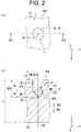
- FIG. 2(a) is an enlarged plan view of one of the seeding hole parts 3.
- FIG. 2(b) is a cross-sectional view taken along a line IIB to IIB of FIG. 2(a) .
- each of the plurality of seeding hole parts 3 extends from the first principal surface F1 toward the second principal surface F2 of the seedbed part 1. Specifically, each of the plurality of seeding hole parts 3 extends from the first principal surface F1 of the seedbed part 1 in a predetermined direction D31.
- the predetermined direction D31 directs from the first principal surface F1 to the second principal surface F2 of the seedbed part 1.
- the predetermined direction D31 is substantially orthogonal to the first principal surface F1 and the second principal surface F2. Therefore, the predetermined direction D31 is substantially orthogonal to the first direction D1 and the second direction D2 shown in FIG. 1 .
- each of the seeding hole parts 3 has a first hole section 31 and a second hole section 32.
- the first hole section 31 extends from the first principal surface F1 of the seedbed part 1 in the predetermined direction D31.
- the second hole section 32 is located farther from the first principal surface F1 of the seedbed part 1 than the first hole section 31.
- the second hole section 32 is connected to the first hole section 31 at a tip end portion of the first hole section 31 in the predetermined direction D31.
- the second hole section 32 extends in the predetermined direction D31 from the tip end portion of the first hole section 31 in the predetermined direction D31.
- the second hole section 32 is tapered in the predetermined direction D31. In other words, a hole width d2 of the second hole section 32 narrows in the predetermined direction D31.
- precision of positions of the seeds SD in the seeding hole parts 3 can be improved.
- the positions of seeds SD in the plurality of seeding hole parts 3 can be prevented from being varied.
- precision of positions of seedlings grown from the seeds SD is also improved. Therefore, damage of the seedlings can be efficiently suppressed when the seedlings are scraped out by planting tines of a transplanting machine.
- the hole width d1 of the first hole section 31 is constant in the predetermined direction D31. Therefore, openings PN of the seeding hole parts 3 can be prevented from becoming excessively large. As a result, strength of the seedling mat 100 can be prevented from being reduced.
- a concept of having the constant hole width d1 of the first hole section 31 includes having a substantially constant hole width d1. Furthermore, the openings PN of the seeding hole parts 3 correspond to openings 31a of the first hole sections 31 on a first principal surface F1 side.
- the seeding hole part when a seeding hole part as a reference example has only of the second hole section 32 without the first hole section 31, for example, the seeding hole part has a substantially inverted conic shape. Therefore, in the reference example, an opening of the seeding hole part may be excessively large. As a result, the strength of the seedling mat may be reduced in the reference example. Furthermore, when openings of the seeding hole parts are excessively large, the openings of the seeding hole parts adjacent to each other may come into contact with each other. As a result, the strength of the seedling mat may be further reduced.
- Each of the first hole sections 31 of the seeding hole parts 3 has a substantially columnar shape.
- the first hole section 31 has a wall surface W1 and a space SP1 surrounded by the wall surface W1.
- the wall surface W1 is a substantially cylindrical surface. Therefore, the space SP1 has a substantially columnar shape.
- the first hole section 31 is linearly symmetrical with respect to an axis line AX of the seeding hole part 3.
- the axis line AX is parallel to the predetermined direction D31.
- the axis line AX is a center line passing through a center of the seeding hole part 3.
- the axis line AX corresponds to an example of an "axis of symmetry".
- the first hole section 31 has a substantially cylindrical shape. Therefore, the wall surface W1 is a substantially cylindrical surface. Furthermore, the space SP1 has a substantially cylindrical shape. Note that the shape of the first hole section 31 is not limited as long as the hole width d1 of the first hole section 31 is constant in the predetermined direction D31.
- the first hole section 31 may have a substantially prism shape
- the wall surface W1 may be a substantially rectangular cylindrical surface
- the space SP1 may have a substantially prism shape.
- a shape of the first hole section 31 in a plan view may be symmetrical or asymmetrical.
- the symmetrical shape is, for example, a substantially circle shape, a substantially polygon shape, or a substantially oval shape.
- the plan view indicates viewing an object in the predetermined direction D31.
- the hole width d1 indicates a length of the first hole section 31 in a direction perpendicular to the predetermined direction D31.
- the hole width d1 is preferably larger than a smallest diameter of the seeds SD.
- the seeds SD can easily reach the second hole sections 32 through the first hole sections 31.
- the hole width d1 may be larger than a largest diameter of the seeds SD. In this case also, the seeds SD can easily reach the second hole sections 32 through the first hole sections 31.
- the second hole sections 32 have a substantially pyramidal shape. Specifically, the second hole section 32 has a wall surface W2 and a space SP2 surrounded by the wall surface W2.
- the wall surface W2 is a substantially conic surface. Therefore, the space SP1 has a substantially pyramidal shape.
- the second hole section 32 is preferably line symmetry with respect to the axis line AX. According to this preferred example, the seed SD can be precisely placed on the axis line AX.
- the second hole section 32 may be asymmetric with respect to the axis line AX as long as the hole width d2 of the second hole section 32 narrows in the predetermined direction D31.
- a position of a tip end portion TP of the second hole section 32 in the predetermined direction D31 is biased with respect to the axis line AX.
- the hole width d2 indicates a length of the second hole section 32 in a direction perpendicular to the predetermined direction D31.
- the second hole section 32 has a substantially conic shape. Therefore, the wall surface W2 is a substantially conic surface. Furthermore, the space SP2 has a substantially conic shape. Note that the shape of the second hole section 32 is not particularly limited as long as the hole width d2 of the second hole section 32 narrows in the predetermined direction D31.
- the second hole section 32 may have a substantially polygonal pyramidal shape
- the wall surface W2 may be a substantially polygonal pyramidal surface
- the space SP2 may have a substantially polygonal pyramid shape.
- the second hole section 32 may have a substantially frustum shape (e.g., a substantially truncated conic shape or a substantially truncated polygonal pyramidal shape), the wall surface W2 may have a substantially frustum surface (e.g., a substantially truncated conic surface or a substantially truncated pyramidal surface), and the space SP2 may have a substantially frustum shape (a substantially truncated conic shape or a substantially truncated polygonal pyramidal shape).
- the second hole section 32 may have a substantially semispherical shape
- the wall surface W2 may be a substantially semispherical surface
- the space SP2 may have a substantially semispherical shape.
- a shape of the second hole section 32 in a plan view may be symmetrical or asymmetrical.
- the symmetrical shape is, for example, a substantially circle shape, a substantially polygon shape, or a substantially oval shape.
- a length H2 of the second hole section 32 in the predetermined direction D31 is shorter than a length H1 of the first hole section 31 in the predetermined direction D31.
- the length H2 may be equal to or larger than the length H1.
- the seeding hole parts 3 have a depth DP3 from the first principal surface F1.
- the depth DP3 is a sum of the length H1 and the length H2.
- the depth DP3 indicates a length of the seeding hole parts 3 in the predetermined direction D31.
- the depth DP3 of the seeding hole parts 3 is smaller than a thickness t of the seedbed part 1. Therefore, the seeding hole parts 3 do not penetrate the seedbed part 1.
- a seedling mat 100A according to a second embodiment of the present invention will be described.
- the second embodiment is different from the first embodiment mainly in that seeding hole parts 3A of the seedling mat 100A of the second embodiment has an extended section 33 that facilitates sowing.
- the following is a description of the main differences of the second embodiment from the first embodiment.
- FIG. 3 is a perspective view of the seedling mat 100A according to the second embodiment.
- the seedling mat 100A includes a seedbed part 1 and a plurality of seeding hole parts 3A.
- Arrangement of the plurality of seeding hole parts 3A is similar to arrangement of the plurality of seeding hole parts 3 described with reference to FIG. 1 .
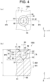
- FIG. 4(a) is a plan view of one of the seeding hole parts 3Athat is enlarged.
- FIG. 4(b) is a cross-sectional view along a IVB-IVB line of FIG. 4(a) .
- each of the plurality of seeding hole parts 3A extends from a first principal surface F1 of the seedbed part 1 toward a second principal surface F2. Specifically, each of the plurality of seeding hole parts 3A extends from the first principal surface F1 of the seedbed part 1 in a predetermined direction D31.
- Each of the plurality of seeding hole parts 3A further has an extended section 33 in addition to the first hole section 31 and the second hole section 32. The extended section 33 is located closer to the first principal surface F1 of the seedbed part 1 than the first hole section 31.
- the extended section 33 extends from an opening edge 31b of the first hole section 31 on the first principal surface F1 side in a radial direction RD relative to an axis line AX of the seeding hole part 3A to the first principal surface F1. Therefore, according to the second embodiment, seeds SD can be easily placed in the seeding hole parts 3A. That is, it is easy to sow the seeds SD into the seeding hole parts 3A.
- the seedling mat 100A according to the second embodiment has the same effects as the seedling mat 100 according to the first embodiment.
- each of the seeding hole parts 3A has an extended section 33
- an opening PN of the seeding hole part 3A is prevented from becoming excessively large. This is because the hole width d1 of the first hole sections 31 that are connected to the extended section 33 is constant.
- the openings PN of the seeding hole parts 3A can be prevented from becoming excessively large, and therefore, the openings PN of the seeding hole parts 3A adjacent to each other can be prevented from coming into contact to each other. As a result, strength of the seedling mat 100A can be prevented from being reduced.
- the openings PN of the seeding hole parts 3A are openings 31a of the extended sections 33 on the first principal surface F1 side.
- each of the extended sections 33 preferably has an inclined surface W3.
- the inclined surface W3 inclines from the first principal surface F1 of the seedbed part 1 toward the opening edge 31b of the first hole section 31. Therefore, according to this preferred example, it is even easier to sow seeds SD into the seeding hole parts 3A.
- the extended sections 33 guide the seeds SD into the first hole sections 31 and the second hole sections 32.
- the inclined surface W3 may be curved.
- the extended sections 33 may have a flat surface that is substantially parallel to the first principal surface F1.
- Each of the extended sections 33 further has a space SP3 surrounded by the inclined surface W3.
- each of the extended sections 33 is provided all around the opening edge 31b along the opening edge 31b of the first hole section 31. Specifically, it is further preferred that each of the extended sections 33 surrounds the opening edge 31b of the first hole section 31 along the opening edge 31b. In this case, the extended section 33 is widened from the opening edge 31b in a direction D32 opposite to the predetermined direction D31. Specifically, the extended section 33 extends so as to become wider from the opening edge 31b in the direction D32 opposite to the predetermined direction D31. Accordingly, it is further easy to sow the seeds SD into the seeding hole parts 3A.
- the extended section 33 may be partially provided corresponding to a portion of the opening edge 31b of the first hole section 31.
- the width d3 of the extended section 33 widens toward the direction D32 opposite to the predetermined direction D31.
- the width d3 indicates a distance between two points on the extended section 33 that are opposite to each other in the radial direction RD through the axis line AX.
- the inclined surface W3 of the extended section 33 is a substantially frustum surface (e.g., a substantially truncated conic surface or a substantially truncated polygonal pyramidal surface).
- the space SP3 of the extended section 33 has a substantially truncated frustum shape (including a substantially truncated conic shape and a substantially truncated polygonal pyramidal shape).
- the extended section 33 is linearly symmetrical with respect to the axis line AX.
- the extended section 33 may be asymmetrical with respect to the axis line AX as long as the extended section 33 extends from the opening edge 31b to the first principal surface F1 in the radial direction RD outward, and a shape of the extended section 33 is not particularly limited.
- a shape of the extended section 33 in a plan view may be symmetrical or asymmetrical.
- Examples of the symmetrical shape include a substantially circular shape and a substantially square ring shape.
- a length H3 of the extended section 33 in the predetermined direction D31 is shorter than the length H1 of the first hole section 31 and shorter than the length H2 of the second hole section 32.
- the relationship between the length H1, the length H2, and the length H3 is not particularly limited.
- the length H3 may be equal to or larger than the length H1, or the length H3 may be equal to or larger than the length H2.
- the seeding hole part 3A has a depth DP3 from the first principal surface F1.
- the depth DP3 is a sum of the lengths H3, H1, and H2.
- the depth DP3 indicates a length of the seeding hole part 3A in the predetermined direction D31.
- the depth DP3 of the seeding hole part 3A is smaller than a thickness t of the seedbed part 1. Therefore, the seeding hole part 3A does not penetrate the seedbed part 1.
- a seedling mat 100B according to a third embodiment of the present invention will be described.
- the third embodiment is different from the second embodiment mainly in that the seedling mat 100B of the third embodiment includes depression sections 5 and first through-hole sections 7 for seeding hole parts 3A.
- the following is a description of the main differences of the third embodiment from the second embodiment.
- FIG. 5 is a perspective view of the seedling mat 100B according to the third embodiment.
- the seedling mat 100B includes a seedbed part 1, a plurality of seeding hole parts 3A, and at least one depression section 5.
- the seedling mat 100B has a plurality of depression sections 5.
- the individual depression sections 5 are provided at different locations in a seedbed part 1 from the plurality of seeding hole parts 3A. In other words, the depression sections 5 are separated from the seeding hole parts 3A.
- Each of the plurality of depression sections 5 is recessed from the first principal surface F1 of the seedbed part 1 in a predetermined direction D31. Specifically, the individual depression sections 5 are recessed relative to the first principal surface F1 of the seedbed part 1. Accordingly, in the third embodiment, air permeability of the seedbed part 1 is improved through the depression sections 5. For example, even when there is excess moisture in the vicinity of seeds SD placed in the seeding hole parts 3A and inside the seedbed part 1, evaporation of the excess moisture can be accelerated by improving the air permeability of the seedbed part 1. As a result, reduction in a germination rate of the seeds SD caused by the excess moisture can be suppressed. Furthermore, spindly growth of seedlings germinated from the seed SDs caused by excessive moisture can be suppressed. In addition, the seedling mat 100B according to the third embodiment has the same effects as the seedling mat 100A according to the second embodiment.
- each of the plurality of depression sections 5 preferably extends from one edge 1A to the other edge 1B of the seedbed part 1 along the first principal surface F1 of the seedbed part 1.
- the air permeability of the seedbed part 1 is further improved through the depression sections 5.
- the reduction in the germination rate of the seeds SD can be further suppressed, and the spindly growth of seedlings germinated from the seeds SD can be further suppressed.
- the depression sections 5 can also improve drainage of the seedbed part 1.
- each of the plurality of depression sections 5 has a substantially groove shape and extends in a substantially straight line in a first direction D1.
- the plurality of depression sections 5 are aligned in a second direction D2 at intervals Lya.
- the plurality of depression sections 5 are substantially parallel to each other.
- the plurality of seeding hole parts 3A are aligned in a straight line in the first direction D1 between the depression sections 5 adjacent to each other.
- the shape of the depression sections 5 is not limited as long as the depression sections 5 are recessed with respect to the first principal surface F1.
- each of the depression sections 5 may not extend from the one edge 1A to the other edge 1B in the seedbed part 1.
- the depression sections 5 may have a segmental shape.
- the seedling mat 100B may have a plurality of segmental depression sections 5.
- the depression sections 5 may have a substantially grid shape.
- the depression sections 5 may be recessed hole sections having a substantially hemispherical shape, recessed hole sections having a substantially semi-elliptical shape, recessed hole sections having a substantially pyramidal shape, or recessed hole sections having a substantially truncated pyramidal shape.
- the seedling mat 100B may have a plurality of depression sections 5 that are hole sections.
- FIG. 6 is a perspective view of a back surface of the seedling mat 100B according to the third embodiment.
- the seedling mat 100B further includes the plurality of first through-hole sections 7.
- the plurality of first through-hole sections 7 are arranged so as to correspond to the plurality of seeding hole parts 3A shown in FIG. 5 .
- FIG. 7(a) is an enlarged plan view of one of the depression sections 5, one of the seeding hole parts 3A, and one of the first through-hole sections 7.
- the depression section 5 is dotted hatched to clarify the drawing.
- FIG. 7(b) is a cross-sectional view taken along a line VIIB to VIIB of FIG. 7(a) .
- the first through-hole sections 7 are arranged so as to correspond to the plurality of seeding hole parts 3A.
- the first through-hole sections 7 are connected to the seeding hole part 3A.
- the first through-hole sections 7 have respective through-spaces SP7.
- the first through-hole sections 7 are positioned farther from the first principal surface F1 of the seedbed part 1 relative to a second hole section 32.
- the first through-hole sections 7 are connected to the respective second hole sections 32.
- Each of the first through-hole sections 7 extends from the second hole section 32 to a second principal surface F2 of the seedbed part 1. Therefore, according to the third embodiment, water permeability of the seedling mat 100B can be improved through the first through-hole sections 7.
- excess water can be discharged outside the seedling mat 100B from the seeding hole parts 3A through the first through-hole sections 7. Therefore, seeds SD can be prevented from getting flooded in the seeding hole parts 3A. As a result, a germination rate of the seeds SD can be improved.
- the first through-hole sections 7 can further improve the air permeability of the seedling mat 100B.
- the first through-hole sections 7 are connected to the respective second hole sections 32 at tip end portions TP of the second hole sections 32 in the predetermined direction D31.
- the first through-hole sections 7 extend from the tip end portions TP of the second hole sections 32 to the second principal surface F2 of the seedbed part 1.
- the water permeability of the seedling mat 100B can be further improved through the first through-hole sections 7. This is because the second hole sections 32 facilitate collection of moisture toward the tip end portions TP. For example, when the seeding hole parts 3A are irrigated, excess water can be effectively discharged outside the seedling mat 100B from the seeding hole parts 3A through the first through-hole sections 7.
- connection points between the first through-hole sections 7 and the second hole sections 32 are not particularly limited as long as the first through-hole sections 7 extend from the second hole sections 32 to the second principal surface F2.
- Each of the first through-hole sections 7 may extend from a wall surface W2 of the second hole section 32 to the second principal surface F2.
- a hole width d7 of the first through-hole section 7 is equal to or smaller than a smallest value of a hole width d2 of the second hole sections 32.
- the hole width d7 of the first through-hole section 7 is smaller than a smallest diameter of a seed SD. Therefore, the seed SD is prevented from entering the through-space SP7 of the first through-hole section 7.
- the hole width d7 of the first through-hole section 7 is preferably equal to or smaller than 1/2 of the smallest diameter of the seed SD. According to this preferred example, the seeds SD are more effectively prevented from entering the through-spaces SP7 of the first through-hole sections 7.
- the hole width d7 indicates a length of the first through-hole section 7 in a direction perpendicular to the predetermined direction D31.
- first through-hole sections 7 extend in a substantially straight line in the predetermined direction D31.
- a shape of the first through-hole sections 7 is not particularly limited as long as the first through-hole sections 7 extend from the second hole sections 32 to the second principal surface F2.
- a shape of the first through-hole sections 7 in a plan view may be symmetrical or asymmetrical.
- the symmetrical shape is, for example, a substantially circle shape, a substantially polygon shape, or a substantially oval shape.
- Each of the depression sections 5 has a depression space SP5.
- Each of the depression sections 5 is separated from a corresponding one of the seeding hole parts 3A (specifically, the extended sections 33) at intervals Lyb in the second direction D2.
- a depth DP5 of the depression sections 5 with respect to the first principal surface F1 of the seedbed part 1 is preferably deeper than the depth DP3 of the seeding hole parts 3A with respect to the first principal surface F1 of the seedbed part 1. According to this preferred example, when there is excess moisture in the seeding hole parts 3A, the moisture in the seeding hole parts 3A easily moves toward the depression sections 5 due to gravity.
- excess water in the seeding hole parts 3A can be effectively discharged.
- the reduction in the germination rate of the seeds SD can be further suppressed, and the spindly growth of seedlings germinated from the seeds SD can be further suppressed.
- the moisture that has moved from the seeding hole parts 3A to the depression sections 5 is discharged outside the seedling mat 100B through the depression sections 5.
- the moisture that has moved from the seeding hole parts 3A to the depression sections 5 is discharged outside the seedling mat 100B through the depression spaces SP5 of the depression sections 5.
- the depression sections 5 have a substantially U-shape (e.g., an angular substantially U-shape) in a cross-sectional view.
- the cross-sectional view indicates viewing an object by cutting the object by a virtual plane perpendicular to the first principal surface F1.
- the shape of the depression sections 5 is not limited as long as the depression sections 5 are recessed with respect to the first principal surface F1.
- the depression sections 5 may have a substantially V-shape in a cross-sectional view.
- the width d5 of the depression sections 5 is substantially the same as the hole width d1 of the first hole sections 31. However, as long as the depression sections 5 are separated from the seeding hole parts 3A, the width d5 of the depression sections 5 may be larger or smaller than the hole width d1 of the first hole sections 31.
- the width d5 indicates a length of the depression sections 5 in a direction perpendicular to the predetermined direction D31.
- the depth DP5 of the depression sections 5 may be substantially the same as the depth DP3 of the seeding hole parts 3A, or the depth DP5 of the depression sections 5 may be shallower than the depth DP3 of the seeding hole parts 3A.
- the depth DP5 indicates a length of the depression sections 5 in the predetermined direction D31.
- the depth DP5 of the depression sections 5 is smaller than a thickness t of the seedbed part 1. Therefore, the depression sections 5 do not penetrate the seedbed part 1.
- the seedling mat 100B may not include one of or both the extended sections 33 and the first through-hole sections 7.
- the seedling mat 100B may not include one of or both the extended sections 33 and the depression sections 5.
- the fourth embodiment is different from the third embodiment mainly in that the seedling mat 100C of the fourth embodiment includes second through-hole sections 9 for depression sections 5.
- the following is a description of the main differences of the fourth embodiment from the third embodiment.
- FIG. 8 is a plan view of the seedling mat 100C according to the fourth embodiment.
- the depression sections 5 are dotted hatched to clarify the drawing.
- the seedling mat 100C further includes at least one second through-hole section 9.
- the seedling mat 100C has a plurality of second through-hole sections 9. Two or more second through-hole sections 9 are arranged for each of the plurality of depression sections 5. The two or more second through-hole sections 9 are arranged along each of the plurality of depression sections 5. Note that one second through-hole section 9 may be located in one depression section 5.
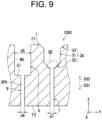
- FIG. 9 is a cross-sectional view taken along a line IX-IX of FIG. 8 .
- Each of the second through-hole sections 9 has a through-space SP9 as illustrated in FIG. 9 .
- the second through-hole sections 9 are positioned separately from a first principal surface F1 of a seedbed part 1 relative to the depression section 5.
- the second through-hole sections 9 are connected to the depression sections 5.
- the second through-hole sections 9 extend from the depression sections 5 to a second principal surface F2 of the seedbed part 1. Therefore, according to the fourth embodiment, the water accumulated in the depression sections 5 can be efficiently discharged outside the seedling mat 100C through the second through-hole sections 9.
- the seedling mat 100C when the seedling mat 100C is irrigated, water accumulated in the depression sections 5 can be effectively discharged outside the seedling mat 100C through the second through-hole sections 9. Furthermore, the second through-hole sections 9 can improve air permeability of the seedling mat 100C.
- the seedling mat 100C according to the fourth embodiment has the same effects as the seedling mat 100B according to the third embodiment.
- the second through-hole sections 9 are connected to the depression sections 5 at bottoms 51 of the depression sections 5.
- the second through-hole sections 9 extend from the bottoms 51 of the depression sections 5 to the second principal surface F2 of the seedbed part 1.
- the water accumulated in the depression sections 5 can be more efficiently discharged outside the seedling mat 100C through the second through-hole sections 9. This is because water accumulated in the depression sections 5 is collected at the bottoms 51.
- connection points between the second through-hole sections 9 and the depression sections 5 are not particularly limited as long as the second through-hole sections 9 extend from the depression sections 5 to the second principal surface F2.
- each of the second through-hole sections 9 may extend from a wall surface W5 of the depression section 5 to the second principal surface F2.
- a hole width d9 of the second through-hole sections 9 is smaller than a width d5 of the depression sections 5.
- the hole width d9 of the second through-hole sections 9 may be substantially the same as the width d5 of the depression sections 5 or larger than the width d5 of the depression sections 5.
- the hole width d9 indicates a length of the second through-hole sections 9 in a direction perpendicular to a predetermined direction D31.
- the second through-hole sections 9 extend in a substantially straight line in the predetermined direction D31.
- a shape of the second through-hole sections 9 is not particularly limited as long as the second through-hole sections 9 extend from the depression sections 5 to the second principal surface F2.
- a shape of the second through-hole sections 9 in a plan view may be symmetrical or asymmetrical.
- the symmetrical shape is, for example, a substantially circle shape, a substantially polygon shape, or a substantially oval shape.
- the seedling mat 100C may not include one of or both extended sections 33 and first through-hole sections 7.
- a seedling mat 100D according to a fifth embodiment of the present invention will be described.
- the fifth embodiment is mainly different from the first embodiment described with reference to FIGS. 1 to 2(b) in that the seedling mat 100D according to the fifth embodiment includes depression sections 5 similarly to FIG. 5 .
- the following is a description of the main differences of the fifth embodiment from the first embodiment.
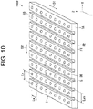
- FIG. 10 is a perspective view of the seedling mat 100D according to the fifth embodiment.
- the seedling mat 100D includes a seedbed part 1, a plurality of seeding hole parts 3B, and at least one depression section 5.
- the seedling mat 100D has a plurality of depression sections 5.
- the individual depression sections 5 are provided at different locations in the seedbed part 1 from the plurality of seeding hole parts 3B.
- the other configurations and arrangements of the depression sections 5 according to the fifth embodiment are the same as those of the depression sections 5 according to the third embodiment described with reference to FIGS. 5 and 7(b) .
- the plurality of seeding hole parts 3B are provided in the seedbed part 1.
- Each of the plurality of seeding hole parts 3B is a hole for placing a seed SD.
- Arrangement of the plurality of seeding hole parts 3B is similar to the arrangement of the plurality of seeding hole parts 3 described with reference to FIG. 1 and the arrangement of the plurality of seeding hole parts 3A described with reference to FIG. 3 .
- FIG. 11(a) is an enlarged plan view of one of the seeding hole parts 3B and one of the depression sections 5.
- the depression section 5 is dotted hatched to clarify the drawing.
- FIG. 11(b) is a cross-sectional view along a XIB-XIB line of FIG. 11(a) .
- each of the plurality of seeding hole parts 3B extends from a first principal surface F1 of the seedbed part 1 toward a second principal surface F2. Specifically, each of the plurality of seeding hole parts 3B extends from the first principal surface F1 of the seedbed part 1 in a predetermined direction D31.
- the other configuration of the seeding hole parts 3B is the same as that of the first hole sections 31 described with reference to FIG. 2(b) .
- a hole width d1 of the seeding hole part 3B is preferably larger than a smallest diameter of a seed SD. Note that, for example, the hole width d1 of the seeding hole part 3B may be larger than a maximum diameter of the seed SD.
- each of the seeding hole parts 3B has a bottom BM in addition to a wall surface W1.
- the seed SD is placed on the bottom BM.
- a configuration of the seeding hole parts 3B is not limited to the configuration of the first hole sections 31 described with reference to FIG. 2(b) , and an arbitrary configuration may be employed.
- the seeding hole parts 3B have a substantially columnar shape (e.g., a substantially cylindrical shape or a substantially prism shape), a substantially pyramidal shape (e.g., a substantially conic shape or a substantially polygonal pyramidal shape), or a substantially truncated pyramidal shape (e.g., a substantially truncated conic shape or a substantially truncated polygonal pyramidal shape).
- a substantially columnar shape e.g., a substantially cylindrical shape or a substantially prism shape
- a substantially pyramidal shape e.g., a substantially conic shape or a substantially polygonal pyramidal shape
- a substantially truncated pyramidal shape e.g., a substantially truncated conic shape or a substantially truncated polygonal pyramidal shape
- each of the depression sections 5 are recessed relative to the first principal surface F1 of the seedbed part 1. Accordingly, as with the third embodiment, the air permeability of the seedbed part 1 is improved through the depression sections 5 according to the fifth embodiment. Effects of improved air permeability of the seedbed part 1 are similar to the effects of the depression sections 5 in the third embodiment. Furthermore, as with the third embodiment, each of the plurality of depression sections 5 preferably extends from one edge 1A to the other edge 1B of the seedbed part 1 along the first principal surface F1 of the seedbed part 1 also in the fifth embodiment. In this case, effects similar to the effects of the depression sections 5 in the third embodiment are attained.
- a depth DP5 of the depression sections 5 with respect to the first principal surface F1 of the seedbed part 1 is preferably deeper than a depth DP3 of the seeding hole parts 3B with respect to the first principal surface F1 of the seedbed part 1 also in the fifth embodiment.
- effects similar to the effects of the depression sections 5 in the third embodiment are attained.
- the depression sections 5 are separated from the seeding hole parts 3B at intervals Lyb in a second direction D2.
- the depth DP5 of the depression sections 5 may be substantially the same as the depth DP3 of the seeding hole parts 3B, or the depth DP5 of the depression sections 5 may be shallower than the depth DP3 of the seeding hole parts 3B.
- the seedling mat 100D may not include one of or both the first through-hole sections 7 and the second through-hole sections 9 described with reference to FIG. 9 .
- the first through-hole sections 7 are connected to the seeding hole parts 3B (specifically, bottoms BM) illustrated in FIG. 11(b) .
- the seeding hole parts 3A may not include the second hole sections 32 and the extended sections 33.
- the seedling mats 100B and 100C may include, instead of the seeding hole parts 3A, the seeding hole parts 3B illustrated in FIG. 11(b) .
- FIGS. 12(a) and 12(b) a seedling mat 100E according to a sixth embodiment of the present invention will be described.
- the sixth embodiment is mainly different from the first embodiment described with reference to FIGS. 1 to 2(b) in that the seedling mat 100E according to the sixth embodiment includes first through-hole sections 7 similarly to FIG. 7(b) .
- the following is a description of the main differences of the sixth embodiment from the first embodiment.
- the sixth embodiment will be described appropriately with reference to FIGS. 1 to 6 .
- FIG. 12(a) is an enlarged plan view of the seedling mat 100E with a seeding hole part 3B and a first through-hole section 7 according to the sixth embodiment.
- the seedling mat 100E includes a seedbed part 1.
- the seedling mat 100E includes a plurality of seeding hole parts 3B illustrated in FIG. 12(a) instead of the plurality of seeding hole parts 3 of the seedling mat 100 illustrated in FIG. 1 .
- the seedling mat 100E further includes the plurality of first through-hole sections 7 illustrated in FIG. 6 .
- the plurality of first through-hole sections 7 are arranged so as to correspond to the plurality of seeding hole parts 3B.
- FIG. 12(b) is a cross-sectional view taken along a line XIIB to XIIB of FIG. 12(a) .
- a configuration of the seeding hole parts 3B according to the sixth embodiment is similar to the configuration of the seeding hole parts 3B illustrated in FIG. 11(b) .
- the configuration of the first through-hole sections 7 according to the sixth embodiment is the same as that of the first through-hole sections 7 shown in FIG. 7(b) .
- the first through-hole sections 7 are positioned separately from the first principal surface F1 of the seedbed part 1 relative to the seeding hole parts 3B.
- the first through-hole sections 7 are connected to the seeding hole parts 3B.
- the first through-hole sections 7 extend to a second principal surface F2 of the seedbed part 1. Therefore, according to the sixth embodiment, water permeability of the seedling mat 100E can be improved through the first through-hole sections 7. Effects of improved water permeability of the seedling mat 100E are similar to the effects of the first through-hole sections 7 in the third embodiment. Furthermore, the first through-hole sections 7 can improve air permeability of the seedling mat 100E.
- the first through-hole sections 7 are connected to the seeding hole parts 3B at bottoms BM of the seeding hole parts 3B.
- the first through-hole sections 7 extend from the bottom BM of the seeding hole parts 3B to a second principal surface F2 of the seedbed part 1.
- connection points between the first through-hole sections 7 and the seeding hole parts 3B are not particularly limited as long as the first through-hole sections 7 extend from the seeding hole parts 3B to the second principal surface F2.
- each of the first through-hole sections 7 may extend from a wall surface W1 of the seeding hole part 3B to the second principal surface F2.
- a hole width d7 of the first through-hole sections 7 is smaller than a size of bottoms BM of the seeding hole parts 3B.
- the hole width d7 of the first through-hole sections 7 is smaller than the hole width d1 of the seeding hole parts 3B.
- the hole width d7 of the first through-hole section 7 is smaller than a smallest diameter of a seed SD. Therefore, the seed SD is prevented from entering the through-space SP7 of the first through-hole section 7.
- the hole width d7 of the first through-hole section 7 is preferably equal to or smaller than 1/2 of the smallest diameter of the seed SD. According to this preferred example, the seeds SD are more effectively prevented from entering the through-spaces SP7 of the first through-hole sections 7.
- the bottoms BM are a substantially flat surface.
- the seedling mat 100E may include the depression sections 5 described with reference to FIGS. 7(b) and 11(b) .
- the depression sections 5 may have the respective second through-hole sections 9 described with reference to FIG. 9 .
- a seedling mat 100F according to a seventh embodiment of the present invention will be described.
- the seventh embodiment is mainly different from the second embodiment described with reference to FIGS. 3 to 4 in that seeding hole parts 3C of the seedling mat 100F according to the seventh embodiment include respective third hole sections 34. Therefore, an entire configuration of the seedling mat 100F according to the seventh embodiment is the same as that of the seedling mat 100A described with reference to FIG. 3 . Furthermore, the seventh embodiment will be described appropriately with reference to FIG. 3 . The following is a description of the main differences of the seventh embodiment from the second embodiment.
- FIG. 13(a) is an enlarged plan view of the seedling mat 100F with one of the seeding hole parts 3C according to the seventh embodiment.
- the seedling mat 100F includes a seedbed part 1.
- the seedling mat 100F includes a plurality of seeding hole parts 3C illustrated in FIG. 13(a) instead of the plurality of seeding hole parts 3A of the seedling mat 100A illustrated in FIG. 3 .
- FIG. 13(b) is a cross-sectional view taken along a line XIIIB to XIIIB of FIG. 13(a) .
- each of the seeding hole parts 3C includes a first hole section 31, a second hole section 32, an extended section 33, and a third hole section 34.
- the third hole section 34 is located closer to a first principal surface F1 of the seedbed part 1 than the extended section 33.
- the third hole section 34 extends from the first principal surface F1 in a predetermined direction D31. In the example in FIG. 13(b) , the third hole section 34 extends in a vertical direction.
- the third hole section 34 is connected to the extended section 33 at an end of the extended section 33 on a first principal surface F1 side.
- the third hole section 34 is connected to an opening edge 33b of the extended section 33 on the first principal surface F1 side.
- an opening 33a and the opening edge 33b are located on a side closer to a second principal surface F2 than to the first principal surface F1 in the extended section 33.
- a hole width d4 of the third hole section 34 is constant in the predetermined direction D31. Accordingly, leaves that have grown from a seed SD grow along the third hole section 34, and therefore, the leaves are prevented from spreading excessively in a horizontal direction. As a result, for example, planting tines of a transplanting machine can be prevented from contacting the leaves, and seedlings can be scraped smoothly from the seedling mat 100F by the planting tines.
- the third hole sections 34 with the constant hole width d4 are placed at an uppermost position, the growth of the leaves from the seeds may be further promoted when compared with a case where the extended sections 33 having inclined surfaces W3 are positioned at the uppermost position.
- a concept of having the constant hole width d4 of the third hole section 34 includes having a substantially constant hole width d4.
- the hole width d4 indicates a length of the third hole section 34 in a direction perpendicular to the predetermined direction D31.
- openings PN of the seeding hole parts 3C are openings 34a of the third hole sections 34 on the first principal surface F1 side.
- the hole width d4 of the third hole sections 34 is larger than the hole width d1 of the first hole sections 31.
- the third hole sections 34 of the seeding hole parts 3C have a substantially columnar shape.
- each of the third hole sections 34 has a wall surface W4 and a space SP4 surrounded by the wall surface W4.
- the wall surface W4 is a substantially cylindrical surface. Therefore, the space SP4 has a substantially columnar shape.
- the third hole section 34 is linearly symmetrical with respect to an axis line AX of the seeding hole part 3C.
- the third hole section 34 has a substantially cylindrical shape. Therefore, the wall surface W4 is a substantially cylindrical surface. Furthermore, the space SP4 has a substantially cylindrical shape. Note that the shape of the third hole section 34 is not limited as long as the hole width d4 of the third hole section 34 is constant in the predetermined direction D31.
- the third hole section 34 may have a substantially prism shape
- the wall surface W4 may be a substantially rectangular cylindrical surface
- the space SP4 may have a substantially prism shape.
- a shape of the third hole section 34 in a plan view may be symmetrical or asymmetrical.
- the symmetrical shape is, for example, a substantially circle shape, a substantially polygon shape, or a substantially oval shape.
- a length H4 of the third hole section 34 in the predetermined direction D31 is shorter than a length H1 of the first hole section 31 in the predetermined direction D31.
- the length H4 of the third hole section 34 is substantially the same as the length H3 of the extended section 33 in the predetermined direction D31.
- the length H4 may be larger or smaller than the length H3.
- the relationship among the lengths H1 to H4 is not particularly limited.
- the seeding hole parts 3C have a depth DP3 from the first principal surface F1.
- the depth DP3 is a sum of the lengths H1 to H4.
- the depth DP3 of the seeding hole parts 3C is smaller than a thickness t of the seedbed part 1. Therefore, the seeding hole parts 3C does not penetrate the seedbed part 1.
- Example 1 with depression, with through-hole, and (depression depth) > (seeding hole depth)
- the seedling mat 100B described with reference to FIGS. 5 to 7(b) is used as a seedling mat according to a first example.
- the seedling mat according to the first example includes the seeding hole parts 3B illustrated in FIG. 11(b) instead of the seeding hole parts 3A illustrated in FIG. 7(b) .
- the seedling mat according to the first example is the seedling mat 100D illustrated in FIG. 11(b) with the first through-hole sections 7 illustrated in FIG. 12(b) added as a configuration.
- Example 2 with depression, without through-hole, and (depression depth) > (seeding hole depth)
- the seedling mat 100D illustrated in FIG. 11(b) is used as a seedling mat according to a second example.
- the depth DP5 of the depression sections 5 is deeper than that of the seeding hole parts 3B.
- Example 3 with depression, without through-hole, and (depression depth) ⁇ (seeding hole depth)
- the seedling mat 100D illustrated in FIG. 11(b) is used as a seedling mat according to a third example.
- the depth DP5 of the depression sections 5 is deeper than that of the seeding hole parts 3B.
- the seedling mat 100E illustrated in FIG. 12(b) is used as a seedling mat according to a fourth example.
- a seedling mat according to a comparative example a seedling mat obtained by omitting the first through-hole sections 7 from the seedling mat 100E illustrated in FIG. 12(b) is used.
- compositions of the seedbed parts 1 are the same.
- a thickness t of the seedbed part 1 is 30 mm.
- a depth DP3 of the seeding hole parts 3A is 10 mm.
- a hole width d1 of the seeding hole parts 3A is 6 mm.
- a width d5 of the depression sections 5 is 6 mm.
- a hole width d7 of the first through-hole sections 7 is 2 mm.
- a distance Lyb between the depression sections 5 and the seeding hole parts 3A is 8.5 mm.
- a distance Lya between the depression sections 5 adjacent to each other is 29 mm.
- a depth DP5 of the depression sections 5 of the second example is 15 mm.
- a depth DP5 of the depression sections 5 of the third example is 15 mm.
- Cabbage seeds are used as seeds SD. Then, 30 seeding hole parts 3B are provided for each of the first to fourth examples and the comparative example, and germination of the seeds SD in 25 days was observed.
- Example 1 Example 2
- Example 3 Comparative Example Germination count / Seeding count 25/30 18/30 6/30 19/30 2/30
- a seedling mat in which seeds are sown includes a seedbed part having first and second principal surfaces that face each other and formed of a material allowing roots to grow, a plurality of seeding hole parts that are arranged in the seedbed part and that are for placing the seeds, and a depression section located in a position different from the plurality of seeding hole parts in the seedbed part, wherein each of the plurality of seeding hole parts extends from the first principal surface to the second principal surface in the seedbed part, and the depression section is recessed with respect to the first principal surface of the seedbed part.
- a seedling mat in which seeds are sown includes a seedbed part having first and second principal surfaces that face each other and formed of a material allowing roots to grow, a plurality of seeding hole parts that are arranged in the seedbed part and that are for placing the seeds, and a plurality of first through-hole sections arranged so as to correspond to the plurality of seeding hole parts, wherein the first through-hole sections are connected to the seeding hole parts and extend to the second principal surface of the seedbed part.
- the present invention relates to a seedling mat and has industrial applicability.
Landscapes
- Life Sciences & Earth Sciences (AREA)
- Environmental Sciences (AREA)
- Soil Sciences (AREA)
- Cultivation Receptacles Or Flower-Pots, Or Pots For Seedlings (AREA)
- Sowing (AREA)
- Chemical & Material Sciences (AREA)
- Inorganic Chemistry (AREA)
- Pretreatment Of Seeds And Plants (AREA)
Abstract
Description
- The present disclosure relates to a seedling mat.
- The seedling mat described in
Patent Document 1 has a lower layer, an intermediate layer, and an upper layer. The upper layer has a plurality of seeding holes at predetermined intervals. - Patent Literature 1:
JP 2019-146537 - However, in the raising seedling mat described in
Patent Literature 1, the seeding holes (seeding hole parts) have a cylindrical or an inverted truncated conic shape. - When the seeding holes are cylindrical in shape, seeds may not be positioned at bottoms of the seeding holes when compared with a case where the seeding holes have an inverted truncated conic shape. For example, in one seeding hole, a seed may be located in a corner of a bottom of the seeding hole, and in another seeding hole, a seed may be located in a center of a bottom of the seeding hole. In other words, when the seeding holes are cylindrical in shape, positions of seeds at bottoms may vary in the plurality of seeding holes when compared with a case where the seeding holes have an inverted truncated conic shape.
- When the seeding holes have an inverted truncated conic shape, upper openings of the seeding holes may be larger than a case where the seeding holes have a cylindrical shape. Therefore, intervals between the seeding holes adjacent to each other may become small. As a result, when the seeding holes have the inverted truncated conic shape, strength of the seedling mat may be reduced when compared to the case where the seeding holes have a cylindrical shape.
- The present disclosure was made in consideration of the above problem, and its object is to provide a seedling mat that can improve precision of positions of seeds in the seeding hole parts while suppressing decrease in strength.
- According to an aspect of the present invention, seeds are sown in a seedling mat. The seedling mat includes a seedbed part and a plurality of seeding hole parts where the seeds are placed. The seedbed part has first and second principal surfaces that face each other. The seedbed part is formed of material that allows roots to grow. The plurality of seeding hole parts are provided in the seedbed part. Each of the seeding hole parts has a first hole section and a second hole section. The first hole section extends in a predetermined direction from the first principal surface of the seedbed part toward the second principal surface. The second hole section is located farther from the first principal surface of the seedbed part than the first hole section. The second hole section is connected to the first hole section. A hole width of the first hole section is constant in the predetermined direction. A hole width of the second hole section narrows in the predetermined direction.
- The present invention can provide a seedling mat that can improve precision of positions of seeds in seeding hole parts while suppressing decrease in strength.
-
-
FIG. 1 is a perspective view of a seedling mat according to a first embodiment of the present invention. -
FIG. 2(a) is an enlarged plan view of the seedling mat with a seeding hole part according to the first embodiment.FIG. 2(b) is a cross-sectional view taken along a line IIB to IIB ofFIG. 2(a) . -
FIG. 3 is a perspective view illustrating a seedling mat according to a second embodiment of the present invention. -
FIG. 4(a) is an enlarged plan view of the seedling mat with a seeding hole part according to the second embodiment.FIG. 4(b) is a cross-sectional view taken along a line IVB to IVB ofFIG. 2(a) . -
FIG. 5 is a perspective view of a seedling mat according to a third embodiment of the present invention. -
FIG. 6 is a perspective view of a back surface of the seedling mat according to the third embodiment. -
FIG. 7(a) is an enlarged plan view of the seedling mat with a seeding hole part, a depression section, and a first through-hole section according to the third embodiment.FIG. 7(b) is a cross-sectional view taken along a line VIIB to VIIB ofFIG. 7(a) . -
FIG. 8 is a plan view of a seedling mat according to a fourth embodiment of the present invention. -
FIG. 9 is a cross-sectional view taken along a line IX to IX ofFIG. 8 . -
FIG. 10 is a perspective view of a seedling mat according to a fifth embodiment of the present invention. -
FIG. 11(a) is an enlarged plan view of the seedling mat with a seeding hole part and a depression section according to the fifth embodiment. -
FIG. 11(b) is a cross-sectional view taken along a line XIB to XIB ofFIG. 11(a) . -
FIG. 12(a) is an enlarged plan view of the seedling mat with a seeding hole part and a first through-hole section according to a sixth embodiment of the present invention.FIG. 12(b) is a cross-sectional view taken along a line XIIB to XIIB ofFIG. 12(a) . -
FIG. 13(a) is an enlarged plan view of the seedling mat with a seeding hole part according to a seventh embodiment of the present invention.FIG. 12(b) is a cross-sectional view taken along a line XIIIB to XIIIB ofFIG. 13(a) . - Embodiments of the present invention will be described hereinafter with reference to the accompanying drawings. Note that, in the drawings, the same reference signs are used for the same or equivalent components, and redundant descriptions are omitted. Furthermore, for facilitating understanding, X, Y, and Z axes of the three-dimensional Cartesian coordinate system are illustrated where appropriate. For example, the X and Y axes are substantially parallel to a horizontal direction, and the Z axis is substantially parallel to a vertical direction.
- Referring to
FIGS. 1 to 2(b) , aseedling mat 100 according to a first embodiment of the present invention will be described. - First, the
seedling mat 100 will be described with reference toFIG. 1. FIG. 1 is a perspective view of theseedling mat 100 according to the first embodiment. A plurality of seeds are sown in theseedling mat 100 shown inFIG. 1 . The seeds are hereinafter referred to as "seeds SD". The seeds SD are, for example, vegetable seeds or paddy seeds. Seedlings grown from the seeds SD are scraped out of theseedling mat 100 by planting tines of a transplanting machine and planted in farmland by the transplanting machine. For example, the planting tines of the transplanting machine scrape out a portion of theseedling mat 100 into blocks, along with seedlings that have grown from the seeds SD. - In the example of
FIG. 1 , theseedling mat 100 has a substantially cuboid shape (e.g., a substantially rectangular flat plate shape). Theseedling mat 100 includes aseedbed part 1 and a plurality of seedinghole parts 3. Theseedbed part 1 has a substantially cuboid shape (e.g., a substantially rectangular flat plate shape). Theseedbed part 1 has a first principal surface F1 and a second principal surface F2. The first and second principal surfaces F1 and F2 face each other and are substantially parallel to each other. For example, among a front surface and a back surface of theseedbed part 1, the first principal surface F1 corresponds to the front surface and the second principal surface F2 corresponds to the back surface. - The
seedbed part 1 is made of material that allows roots of the seeds SD to grow. Theseedbed part 1 includes at least organic fiber material, for example. Organic fiber material is fiber material composed of an organic matter. Examples of the organic fiber material include coco peat, peat moss, and rice husks. Alternatively, theseedbed part 1 may include binders, soil conditioners, fertilizers, and/or soil, for example. - A plurality of seeding
hole parts 3 are provided in theseedbed part 1. Each of the plurality of seedinghole parts 3 is a hole for placing a seed SD. Therefore, the seeds SD are sown in the individualseeding hole parts 3. - In the example shown in
FIG, 1 , the plurality of seedinghole parts 3 are arranged in a substantially square grid or substantially rectangular grid. Specifically, two or more seedinghole parts 3 are arranged in a straight line in a first direction D1. The seedinghole parts 3 adjacent to each other in the first direction D1 are arranged with an interval Lx. Furthermore, two or more seedinghole parts 3 are arranged in a straight line in a second direction D2. The seedinghole parts 3 adjacent to each other in the second direction D2 are arranged with an interval Ly. The intervals Lx and Ly may be the same or different. The first direction D1 and the second direction D2 are substantially parallel to the first principal surface F1. The first direction D1 and the second direction D2 are substantially orthogonal to each other. - Next, the seeding
hole parts 3 will be described with reference toFIGS. 2(a) and 2(b). FIG. 2(a) is an enlarged plan view of one of the seedinghole parts 3.FIG. 2(b) is a cross-sectional view taken along a line IIB to IIB ofFIG. 2(a) . - As shown in
FIG. 2(b) , each of the plurality of seedinghole parts 3 extends from the first principal surface F1 toward the second principal surface F2 of theseedbed part 1. Specifically, each of the plurality of seedinghole parts 3 extends from the first principal surface F1 of theseedbed part 1 in a predetermined direction D31. The predetermined direction D31 directs from the first principal surface F1 to the second principal surface F2 of theseedbed part 1. In the example ofFIG. 2(b) , the predetermined direction D31 is substantially orthogonal to the first principal surface F1 and the second principal surface F2. Therefore, the predetermined direction D31 is substantially orthogonal to the first direction D1 and the second direction D2 shown inFIG. 1 . - Specifically, each of the seeding
hole parts 3 has afirst hole section 31 and asecond hole section 32. Thefirst hole section 31 extends from the first principal surface F1 of theseedbed part 1 in the predetermined direction D31. Thesecond hole section 32 is located farther from the first principal surface F1 of theseedbed part 1 than thefirst hole section 31. Thesecond hole section 32 is connected to thefirst hole section 31 at a tip end portion of thefirst hole section 31 in the predetermined direction D31. In other words, thesecond hole section 32 extends in the predetermined direction D31 from the tip end portion of thefirst hole section 31 in the predetermined direction D31. Thesecond hole section 32 is tapered in the predetermined direction D31. In other words, a hole width d2 of thesecond hole section 32 narrows in the predetermined direction D31. - Therefore, according to the first embodiment, precision of positions of the seeds SD in the seeding
hole parts 3 can be improved. For example, the positions of seeds SD in the plurality of seedinghole parts 3 can be prevented from being varied. When the precision of the positions of the seeds SD in the seedinghole parts 3 can be improved, precision of positions of seedlings grown from the seeds SD is also improved. Therefore, damage of the seedlings can be efficiently suppressed when the seedlings are scraped out by planting tines of a transplanting machine. - In addition, according to the first embodiment, the hole width d1 of the
first hole section 31 is constant in the predetermined direction D31. Therefore, openings PN of the seedinghole parts 3 can be prevented from becoming excessively large. As a result, strength of theseedling mat 100 can be prevented from being reduced. In this specification, a concept of having the constant hole width d1 of thefirst hole section 31 includes having a substantially constant hole width d1. Furthermore, the openings PN of the seedinghole parts 3 correspond toopenings 31a of thefirst hole sections 31 on a first principal surface F1 side. - Note that, when a seeding hole part as a reference example has only of the
second hole section 32 without thefirst hole section 31, for example, the seeding hole part has a substantially inverted conic shape. Therefore, in the reference example, an opening of the seeding hole part may be excessively large. As a result, the strength of the seedling mat may be reduced in the reference example. Furthermore, when openings of the seeding hole parts are excessively large, the openings of the seeding hole parts adjacent to each other may come into contact with each other. As a result, the strength of the seedling mat may be further reduced. - As described above with reference to
FIG. 2(b) , according to the first embodiment, precision of the positions of the seeds SD in the seedinghole parts 3 can be improved while reduction of the strength of theseedling mat 100 is suppressed. - Next, the seeding
hole parts 3 will be described with reference toFIG. 2(a) and FIG. 2(b) . Each of thefirst hole sections 31 of the seedinghole parts 3 has a substantially columnar shape. Specifically, thefirst hole section 31 has a wall surface W1 and a space SP1 surrounded by the wall surface W1. The wall surface W1 is a substantially cylindrical surface. Therefore, the space SP1 has a substantially columnar shape. Thefirst hole section 31 is linearly symmetrical with respect to an axis line AX of the seedinghole part 3. The axis line AX is parallel to the predetermined direction D31. In the example ofFIG. 2(b) , the axis line AX is a center line passing through a center of the seedinghole part 3. The axis line AX corresponds to an example of an "axis of symmetry". - In the examples of
FIGS. 2(a) and 2(b) , thefirst hole section 31 has a substantially cylindrical shape. Therefore, the wall surface W1 is a substantially cylindrical surface. Furthermore, the space SP1 has a substantially cylindrical shape. Note that the shape of thefirst hole section 31 is not limited as long as the hole width d1 of thefirst hole section 31 is constant in the predetermined direction D31. For example, thefirst hole section 31 may have a substantially prism shape, the wall surface W1 may be a substantially rectangular cylindrical surface, and the space SP1 may have a substantially prism shape. For example, a shape of thefirst hole section 31 in a plan view may be symmetrical or asymmetrical. The symmetrical shape is, for example, a substantially circle shape, a substantially polygon shape, or a substantially oval shape. In this specification, the plan view indicates viewing an object in the predetermined direction D31. The hole width d1 indicates a length of thefirst hole section 31 in a direction perpendicular to the predetermined direction D31. The hole width d1 is preferably larger than a smallest diameter of the seeds SD. For example, in elongated seeds SD (e.g. cucumber), even in a case where an inequality "(a smallest diameter of the seeds SD) < (the hole width d1) < (a largest diameter of the seeds SD)" is satisfied, the seeds SD can easily reach thesecond hole sections 32 through thefirst hole sections 31. For example, the hole width d1 may be larger than a largest diameter of the seeds SD. In this case also, the seeds SD can easily reach thesecond hole sections 32 through thefirst hole sections 31. - The
second hole sections 32 have a substantially pyramidal shape. Specifically, thesecond hole section 32 has a wall surface W2 and a space SP2 surrounded by the wall surface W2. The wall surface W2 is a substantially conic surface. Therefore, the space SP1 has a substantially pyramidal shape. In particular, thesecond hole section 32 is preferably line symmetry with respect to the axis line AX. According to this preferred example, the seed SD can be precisely placed on the axis line AX. Note that thesecond hole section 32 may be asymmetric with respect to the axis line AX as long as the hole width d2 of thesecond hole section 32 narrows in the predetermined direction D31. In this case, for example, a position of a tip end portion TP of thesecond hole section 32 in the predetermined direction D31 is biased with respect to the axis line AX. Note that the hole width d2 indicates a length of thesecond hole section 32 in a direction perpendicular to the predetermined direction D31. - In the examples of
FIGS. 2(a) and 2(b) , thesecond hole section 32 has a substantially conic shape. Therefore, the wall surface W2 is a substantially conic surface. Furthermore, the space SP2 has a substantially conic shape. Note that the shape of thesecond hole section 32 is not particularly limited as long as the hole width d2 of thesecond hole section 32 narrows in the predetermined direction D31. For example, thesecond hole section 32 may have a substantially polygonal pyramidal shape, the wall surface W2 may be a substantially polygonal pyramidal surface, and the space SP2 may have a substantially polygonal pyramid shape. For example, thesecond hole section 32 may have a substantially frustum shape (e.g., a substantially truncated conic shape or a substantially truncated polygonal pyramidal shape), the wall surface W2 may have a substantially frustum surface (e.g., a substantially truncated conic surface or a substantially truncated pyramidal surface), and the space SP2 may have a substantially frustum shape (a substantially truncated conic shape or a substantially truncated polygonal pyramidal shape). For example, thesecond hole section 32 may have a substantially semispherical shape, the wall surface W2 may be a substantially semispherical surface, and the space SP2 may have a substantially semispherical shape. For example, a shape of thesecond hole section 32 in a plan view may be symmetrical or asymmetrical. The symmetrical shape is, for example, a substantially circle shape, a substantially polygon shape, or a substantially oval shape. - Note that, in the example of
FIG. 2(b) , a length H2 of thesecond hole section 32 in the predetermined direction D31 is shorter than a length H1 of thefirst hole section 31 in the predetermined direction D31. However, the length H2 may be equal to or larger than the length H1. The seedinghole parts 3 have a depth DP3 from the first principal surface F1. The depth DP3 is a sum of the length H1 and the length H2. In other words, the depth DP3 indicates a length of the seedinghole parts 3 in the predetermined direction D31. The depth DP3 of the seedinghole parts 3 is smaller than a thickness t of theseedbed part 1. Therefore, the seedinghole parts 3 do not penetrate theseedbed part 1. - Referring to
FIGS. 3 to 4(b) , aseedling mat 100A according to a second embodiment of the present invention will be described. The second embodiment is different from the first embodiment mainly in that seedinghole parts 3A of theseedling mat 100A of the second embodiment has an extendedsection 33 that facilitates sowing. The following is a description of the main differences of the second embodiment from the first embodiment. - First, the
seedling mat 100A will be described with reference toFIG. 3. FIG. 3 is a perspective view of theseedling mat 100A according to the second embodiment. As shown inFIG. 3 , theseedling mat 100A includes aseedbed part 1 and a plurality of seedinghole parts 3A. Arrangement of the plurality of seedinghole parts 3A is similar to arrangement of the plurality of seedinghole parts 3 described with reference toFIG. 1 . - Next, the seeding
hole parts 3A will be described with reference toFIG. 4(a) and FIG. 4(b). FIG. 4(a) is a plan view of one of the seeding hole parts 3Athat is enlarged.FIG. 4(b) is a cross-sectional view along a IVB-IVB line ofFIG. 4(a) . - As shown in
FIGS. 4(a) and 4(b) , each of the plurality of seedinghole parts 3A extends from a first principal surface F1 of theseedbed part 1 toward a second principal surface F2. Specifically, each of the plurality of seedinghole parts 3A extends from the first principal surface F1 of theseedbed part 1 in a predetermined direction D31. Each of the plurality of seedinghole parts 3A further has an extendedsection 33 in addition to thefirst hole section 31 and thesecond hole section 32. Theextended section 33 is located closer to the first principal surface F1 of theseedbed part 1 than thefirst hole section 31. Theextended section 33 extends from anopening edge 31b of thefirst hole section 31 on the first principal surface F1 side in a radial direction RD relative to an axis line AX of the seedinghole part 3A to the first principal surface F1. Therefore, according to the second embodiment, seeds SD can be easily placed in the seedinghole parts 3A. That is, it is easy to sow the seeds SD into the seedinghole parts 3A. Theseedling mat 100A according to the second embodiment has the same effects as theseedling mat 100 according to the first embodiment. - Furthermore, in the second embodiment, even though each of the seeding
hole parts 3A has an extendedsection 33, an opening PN of the seedinghole part 3A is prevented from becoming excessively large. This is because the hole width d1 of thefirst hole sections 31 that are connected to theextended section 33 is constant. In the second embodiment, the openings PN of the seedinghole parts 3A can be prevented from becoming excessively large, and therefore, the openings PN of the seedinghole parts 3A adjacent to each other can be prevented from coming into contact to each other. As a result, strength of theseedling mat 100A can be prevented from being reduced. Note that the openings PN of the seedinghole parts 3A areopenings 31a of theextended sections 33 on the first principal surface F1 side. - In particular, in the second embodiment, each of the
extended sections 33 preferably has an inclined surface W3. The inclined surface W3 inclines from the first principal surface F1 of theseedbed part 1 toward the openingedge 31b of thefirst hole section 31. Therefore, according to this preferred example, it is even easier to sow seeds SD into the seedinghole parts 3A. For example, theextended sections 33 guide the seeds SD into thefirst hole sections 31 and thesecond hole sections 32. The inclined surface W3 may be curved. Note that theextended sections 33 may have a flat surface that is substantially parallel to the first principal surface F1. Each of theextended sections 33 further has a space SP3 surrounded by the inclined surface W3. - It is further preferred that each of the
extended sections 33 is provided all around the openingedge 31b along the openingedge 31b of thefirst hole section 31. Specifically, it is further preferred that each of theextended sections 33 surrounds the openingedge 31b of thefirst hole section 31 along the openingedge 31b. In this case, theextended section 33 is widened from the openingedge 31b in a direction D32 opposite to the predetermined direction D31. Specifically, theextended section 33 extends so as to become wider from the openingedge 31b in the direction D32 opposite to the predetermined direction D31. Accordingly, it is further easy to sow the seeds SD into the seedinghole parts 3A. Theextended section 33 may be partially provided corresponding to a portion of theopening edge 31b of thefirst hole section 31. - More specifically, the width d3 of the
extended section 33 widens toward the direction D32 opposite to the predetermined direction D31. The width d3 indicates a distance between two points on theextended section 33 that are opposite to each other in the radial direction RD through the axis line AX. The inclined surface W3 of theextended section 33 is a substantially frustum surface (e.g., a substantially truncated conic surface or a substantially truncated polygonal pyramidal surface). The space SP3 of theextended section 33 has a substantially truncated frustum shape (including a substantially truncated conic shape and a substantially truncated polygonal pyramidal shape). Furthermore, theextended section 33 is linearly symmetrical with respect to the axis line AX. Theextended section 33 may be asymmetrical with respect to the axis line AX as long as theextended section 33 extends from the openingedge 31b to the first principal surface F1 in the radial direction RD outward, and a shape of theextended section 33 is not particularly limited. For example, a shape of theextended section 33 in a plan view may be symmetrical or asymmetrical. Examples of the symmetrical shape include a substantially circular shape and a substantially square ring shape. - Note that, in the example of
FIG. 4(b) , a length H3 of theextended section 33 in the predetermined direction D31 is shorter than the length H1 of thefirst hole section 31 and shorter than the length H2 of thesecond hole section 32. However, the relationship between the length H1, the length H2, and the length H3 is not particularly limited. For example, the length H3 may be equal to or larger than the length H1, or the length H3 may be equal to or larger than the length H2. Furthermore, the seedinghole part 3A has a depth DP3 from the first principal surface F1. The depth DP3 is a sum of the lengths H3, H1, and H2. In other words, the depth DP3 indicates a length of the seedinghole part 3A in the predetermined direction D31. The depth DP3 of the seedinghole part 3A is smaller than a thickness t of theseedbed part 1. Therefore, the seedinghole part 3A does not penetrate theseedbed part 1. - Referring to
FIGS. 5 to 7(b) , aseedling mat 100B according to a third embodiment of the present invention will be described. The third embodiment is different from the second embodiment mainly in that theseedling mat 100B of the third embodiment includesdepression sections 5 and first through-hole sections 7 for seedinghole parts 3A. The following is a description of the main differences of the third embodiment from the second embodiment. - First, the
seedling mat 100B will be described with reference toFIGS. 5 and6 .FIG. 5 is a perspective view of theseedling mat 100B according to the third embodiment. As illustrated inFIG. 5 , theseedling mat 100B includes aseedbed part 1, a plurality of seedinghole parts 3A, and at least onedepression section 5. In the example inFIG. 5 , theseedling mat 100B has a plurality ofdepression sections 5. Theindividual depression sections 5 are provided at different locations in aseedbed part 1 from the plurality of seedinghole parts 3A. In other words, thedepression sections 5 are separated from the seedinghole parts 3A. - Each of the plurality of
depression sections 5 is recessed from the first principal surface F1 of theseedbed part 1 in a predetermined direction D31. Specifically, theindividual depression sections 5 are recessed relative to the first principal surface F1 of theseedbed part 1. Accordingly, in the third embodiment, air permeability of theseedbed part 1 is improved through thedepression sections 5. For example, even when there is excess moisture in the vicinity of seeds SD placed in the seedinghole parts 3A and inside theseedbed part 1, evaporation of the excess moisture can be accelerated by improving the air permeability of theseedbed part 1. As a result, reduction in a germination rate of the seeds SD caused by the excess moisture can be suppressed. Furthermore, spindly growth of seedlings germinated from the seed SDs caused by excessive moisture can be suppressed. In addition, theseedling mat 100B according to the third embodiment has the same effects as theseedling mat 100A according to the second embodiment. - In particular, in the third embodiment, each of the plurality of
depression sections 5 preferably extends from oneedge 1A to theother edge 1B of theseedbed part 1 along the first principal surface F1 of theseedbed part 1. According to this preferred example, the air permeability of theseedbed part 1 is further improved through thedepression sections 5. As a result, for example, the reduction in the germination rate of the seeds SD can be further suppressed, and the spindly growth of seedlings germinated from the seeds SD can be further suppressed. Thedepression sections 5 can also improve drainage of theseedbed part 1. - In the example of
FIG. 5 , each of the plurality ofdepression sections 5 has a substantially groove shape and extends in a substantially straight line in a first direction D1. The plurality ofdepression sections 5 are aligned in a second direction D2 at intervals Lya. The plurality ofdepression sections 5 are substantially parallel to each other. The plurality of seedinghole parts 3A are aligned in a straight line in the first direction D1 between thedepression sections 5 adjacent to each other. - The shape of the
depression sections 5 is not limited as long as thedepression sections 5 are recessed with respect to the first principal surface F1. For example, each of thedepression sections 5 may not extend from the oneedge 1A to theother edge 1B in theseedbed part 1. For example, thedepression sections 5 may have a segmental shape. In this case, theseedling mat 100B may have a plurality ofsegmental depression sections 5. For example, thedepression sections 5 may have a substantially grid shape. For example, thedepression sections 5 may be recessed hole sections having a substantially hemispherical shape, recessed hole sections having a substantially semi-elliptical shape, recessed hole sections having a substantially pyramidal shape, or recessed hole sections having a substantially truncated pyramidal shape. In this case, theseedling mat 100B may have a plurality ofdepression sections 5 that are hole sections. -
FIG. 6 is a perspective view of a back surface of theseedling mat 100B according to the third embodiment. As shown inFIG. 6 , theseedling mat 100B further includes the plurality of first through-hole sections 7. The plurality of first through-hole sections 7 are arranged so as to correspond to the plurality of seedinghole parts 3A shown inFIG. 5 . - Next, the first through-
hole sections 7 will be described with reference toFIGS. 7(a) and 7(b). FIG. 7(a) is an enlarged plan view of one of thedepression sections 5, one of the seedinghole parts 3A, and one of the first through-hole sections 7. InFIG. 7(a) , thedepression section 5 is dotted hatched to clarify the drawing.FIG. 7(b) is a cross-sectional view taken along a line VIIB to VIIB ofFIG. 7(a) . - As shown in
FIG. 7(b) , the first through-hole sections 7 are arranged so as to correspond to the plurality of seedinghole parts 3A. The first through-hole sections 7 are connected to the seedinghole part 3A. The first through-hole sections 7 have respective through-spaces SP7. - Specifically, the first through-
hole sections 7 are positioned farther from the first principal surface F1 of theseedbed part 1 relative to asecond hole section 32. The first through-hole sections 7 are connected to the respectivesecond hole sections 32. Each of the first through-hole sections 7 extends from thesecond hole section 32 to a second principal surface F2 of theseedbed part 1. Therefore, according to the third embodiment, water permeability of theseedling mat 100B can be improved through the first through-hole sections 7. For example, when the seedinghole parts 3A are irrigated, excess water can be discharged outside theseedling mat 100B from the seedinghole parts 3A through the first through-hole sections 7. Therefore, seeds SD can be prevented from getting flooded in the seedinghole parts 3A. As a result, a germination rate of the seeds SD can be improved. The first through-hole sections 7 can further improve the air permeability of theseedling mat 100B. - The first through-
hole sections 7 are connected to the respectivesecond hole sections 32 at tip end portions TP of thesecond hole sections 32 in the predetermined direction D31. The first through-hole sections 7 extend from the tip end portions TP of thesecond hole sections 32 to the second principal surface F2 of theseedbed part 1. In this preferred example, the water permeability of theseedling mat 100B can be further improved through the first through-hole sections 7. This is because thesecond hole sections 32 facilitate collection of moisture toward the tip end portions TP. For example, when the seedinghole parts 3A are irrigated, excess water can be effectively discharged outside theseedling mat 100B from the seedinghole parts 3A through the first through-hole sections 7. Note that connection points between the first through-hole sections 7 and thesecond hole sections 32 are not particularly limited as long as the first through-hole sections 7 extend from thesecond hole sections 32 to the second principal surface F2. For example, Each of the first through-hole sections 7 may extend from a wall surface W2 of thesecond hole section 32 to the second principal surface F2. - Furthermore, in the example in
FIG. 7(b) , a hole width d7 of the first through-hole section 7 is equal to or smaller than a smallest value of a hole width d2 of thesecond hole sections 32. Specifically, the hole width d7 of the first through-hole section 7 is smaller than a smallest diameter of a seed SD. Therefore, the seed SD is prevented from entering the through-space SP7 of the first through-hole section 7. The hole width d7 of the first through-hole section 7 is preferably equal to or smaller than 1/2 of the smallest diameter of the seed SD. According to this preferred example, the seeds SD are more effectively prevented from entering the through-spaces SP7 of the first through-hole sections 7. Note that the hole width d7 indicates a length of the first through-hole section 7 in a direction perpendicular to the predetermined direction D31. - Furthermore, the first through-
hole sections 7 extend in a substantially straight line in the predetermined direction D31. Note that a shape of the first through-hole sections 7 is not particularly limited as long as the first through-hole sections 7 extend from thesecond hole sections 32 to the second principal surface F2. For example, a shape of the first through-hole sections 7 in a plan view may be symmetrical or asymmetrical. The symmetrical shape is, for example, a substantially circle shape, a substantially polygon shape, or a substantially oval shape. - Next, the
depression sections 5 will be described in detail with reference toFIG. 7(b) . Each of thedepression sections 5 has a depression space SP5. Each of thedepression sections 5 is separated from a corresponding one of the seedinghole parts 3A (specifically, the extended sections 33) at intervals Lyb in the second direction D2. A depth DP5 of thedepression sections 5 with respect to the first principal surface F1 of theseedbed part 1 is preferably deeper than the depth DP3 of the seedinghole parts 3A with respect to the first principal surface F1 of theseedbed part 1. According to this preferred example, when there is excess moisture in the seedinghole parts 3A, the moisture in the seedinghole parts 3A easily moves toward thedepression sections 5 due to gravity. In other words, excess water in the seeding hole parts 3Acan be effectively discharged. As a result, for example, the reduction in the germination rate of the seeds SD can be further suppressed, and the spindly growth of seedlings germinated from the seeds SD can be further suppressed. The moisture that has moved from the seedinghole parts 3A to thedepression sections 5 is discharged outside theseedling mat 100B through thedepression sections 5. Specifically, the moisture that has moved from the seedinghole parts 3A to thedepression sections 5 is discharged outside theseedling mat 100B through the depression spaces SP5 of thedepression sections 5. - In the example of
FIG. 7(b) , thedepression sections 5 have a substantially U-shape (e.g., an angular substantially U-shape) in a cross-sectional view. In this specification, the cross-sectional view indicates viewing an object by cutting the object by a virtual plane perpendicular to the first principal surface F1. Note that the shape of thedepression sections 5 is not limited as long as thedepression sections 5 are recessed with respect to the first principal surface F1. For example, thedepression sections 5 may have a substantially V-shape in a cross-sectional view. - In the example in
FIG. 7(b) , the width d5 of thedepression sections 5 is substantially the same as the hole width d1 of thefirst hole sections 31. However, as long as thedepression sections 5 are separated from the seedinghole parts 3A, the width d5 of thedepression sections 5 may be larger or smaller than the hole width d1 of thefirst hole sections 31. The width d5 indicates a length of thedepression sections 5 in a direction perpendicular to the predetermined direction D31. Furthermore, the depth DP5 of thedepression sections 5 may be substantially the same as the depth DP3 of the seedinghole parts 3A, or the depth DP5 of thedepression sections 5 may be shallower than the depth DP3 of the seedinghole parts 3A. The depth DP5 indicates a length of thedepression sections 5 in the predetermined direction D31. The depth DP5 of thedepression sections 5 is smaller than a thickness t of theseedbed part 1. Therefore, thedepression sections 5 do not penetrate theseedbed part 1. - Furthermore, in the third embodiment, the
seedling mat 100B may not include one of or both theextended sections 33 and the first through-hole sections 7. Alternatively, theseedling mat 100B may not include one of or both theextended sections 33 and thedepression sections 5. - Referring to
FIGS. 8 and9 , aseedling mat 100C according to a fourth embodiment of the present invention will be described. The fourth embodiment is different from the third embodiment mainly in that theseedling mat 100C of the fourth embodiment includes second through-hole sections 9 fordepression sections 5. The following is a description of the main differences of the fourth embodiment from the third embodiment. - First, the
seedling mat 100C will be described with reference toFIG. 8. FIG. 8 is a plan view of theseedling mat 100C according to the fourth embodiment. InFIG. 8 , thedepression sections 5 are dotted hatched to clarify the drawing. As shown inFIG. 8 , theseedling mat 100C further includes at least one second through-hole section 9. In the example inFIG. 8 , theseedling mat 100C has a plurality of second through-hole sections 9. Two or more second through-hole sections 9 are arranged for each of the plurality ofdepression sections 5. The two or more second through-hole sections 9 are arranged along each of the plurality ofdepression sections 5. Note that one second through-hole section 9 may be located in onedepression section 5. - Next, the second through-
hole sections 9 will be described in detail with reference toFIG. 9. FIG. 9 is a cross-sectional view taken along a line IX-IX ofFIG. 8 . Each of the second through-hole sections 9 has a through-space SP9 as illustrated inFIG. 9 . The second through-hole sections 9 are positioned separately from a first principal surface F1 of aseedbed part 1 relative to thedepression section 5. The second through-hole sections 9 are connected to thedepression sections 5. The second through-hole sections 9 extend from thedepression sections 5 to a second principal surface F2 of theseedbed part 1. Therefore, according to the fourth embodiment, the water accumulated in thedepression sections 5 can be efficiently discharged outside theseedling mat 100C through the second through-hole sections 9. For example, when theseedling mat 100C is irrigated, water accumulated in thedepression sections 5 can be effectively discharged outside theseedling mat 100C through the second through-hole sections 9. Furthermore, the second through-hole sections 9 can improve air permeability of theseedling mat 100C. In addition, theseedling mat 100C according to the fourth embodiment has the same effects as theseedling mat 100B according to the third embodiment. - Preferably, the second through-
hole sections 9 are connected to thedepression sections 5 atbottoms 51 of thedepression sections 5. The second through-hole sections 9 extend from thebottoms 51 of thedepression sections 5 to the second principal surface F2 of theseedbed part 1. In this preferred example, the water accumulated in thedepression sections 5 can be more efficiently discharged outside theseedling mat 100C through the second through-hole sections 9. This is because water accumulated in thedepression sections 5 is collected at thebottoms 51. Note that connection points between the second through-hole sections 9 and thedepression sections 5 are not particularly limited as long as the second through-hole sections 9 extend from thedepression sections 5 to the second principal surface F2. For example, each of the second through-hole sections 9 may extend from a wall surface W5 of thedepression section 5 to the second principal surface F2. - In the example of
FIG. 9 , a hole width d9 of the second through-hole sections 9 is smaller than a width d5 of thedepression sections 5. However, the hole width d9 of the second through-hole sections 9 may be substantially the same as the width d5 of thedepression sections 5 or larger than the width d5 of thedepression sections 5. Note that the hole width d9 indicates a length of the second through-hole sections 9 in a direction perpendicular to a predetermined direction D31. Furthermore, the second through-hole sections 9 extend in a substantially straight line in the predetermined direction D31. Note that a shape of the second through-hole sections 9 is not particularly limited as long as the second through-hole sections 9 extend from thedepression sections 5 to the second principal surface F2. For example, a shape of the second through-hole sections 9 in a plan view may be symmetrical or asymmetrical. The symmetrical shape is, for example, a substantially circle shape, a substantially polygon shape, or a substantially oval shape. - Furthermore, in the fourth embodiment, the
seedling mat 100C may not include one of or bothextended sections 33 and first through-hole sections 7. - Referring to
FIGS. 10 to 11(b) , aseedling mat 100D according to a fifth embodiment of the present invention will be described. The fifth embodiment is mainly different from the first embodiment described with reference toFIGS. 1 to 2(b) in that theseedling mat 100D according to the fifth embodiment includesdepression sections 5 similarly toFIG. 5 . The following is a description of the main differences of the fifth embodiment from the first embodiment. - First, the
seedling mat 100D will be described with reference toFIG. 10. FIG. 10 is a perspective view of theseedling mat 100D according to the fifth embodiment. As illustrated inFIG. 10 , theseedling mat 100D includes aseedbed part 1, a plurality of seedinghole parts 3B, and at least onedepression section 5. In the example inFIG. 10 , theseedling mat 100D has a plurality ofdepression sections 5. Theindividual depression sections 5 are provided at different locations in theseedbed part 1 from the plurality of seedinghole parts 3B. The other configurations and arrangements of thedepression sections 5 according to the fifth embodiment are the same as those of thedepression sections 5 according to the third embodiment described with reference toFIGS. 5 and7(b) . - The plurality of seeding
hole parts 3B are provided in theseedbed part 1. Each of the plurality of seedinghole parts 3B is a hole for placing a seed SD. Arrangement of the plurality of seedinghole parts 3B is similar to the arrangement of the plurality of seedinghole parts 3 described with reference toFIG. 1 and the arrangement of the plurality of seedinghole parts 3A described with reference toFIG. 3 . - Next, the seeding
hole parts 3B and thedepression sections 5 will be described with reference toFIGS. 11(a) and 11(b). FIG. 11(a) is an enlarged plan view of one of the seedinghole parts 3B and one of thedepression sections 5. InFIG. 11(a) , thedepression section 5 is dotted hatched to clarify the drawing.FIG. 11(b) is a cross-sectional view along a XIB-XIB line ofFIG. 11(a) . - As shown in
FIG. 11(b) , each of the plurality of seedinghole parts 3B extends from a first principal surface F1 of theseedbed part 1 toward a second principal surface F2. Specifically, each of the plurality of seedinghole parts 3B extends from the first principal surface F1 of theseedbed part 1 in a predetermined direction D31. The other configuration of the seedinghole parts 3B is the same as that of thefirst hole sections 31 described with reference toFIG. 2(b) . A hole width d1 of the seedinghole part 3B is preferably larger than a smallest diameter of a seed SD. Note that, for example, the hole width d1 of the seedinghole part 3B may be larger than a maximum diameter of the seed SD. However, in the fifth embodiment, each of the seedinghole parts 3B has a bottom BM in addition to a wall surface W1. The seed SD is placed on the bottom BM. Furthermore, in the fifth embodiment, as long as theseedling mat 100D includes thedepression sections 5, a configuration of the seedinghole parts 3B is not limited to the configuration of thefirst hole sections 31 described with reference toFIG. 2(b) , and an arbitrary configuration may be employed. For example, the seedinghole parts 3B have a substantially columnar shape (e.g., a substantially cylindrical shape or a substantially prism shape), a substantially pyramidal shape (e.g., a substantially conic shape or a substantially polygonal pyramidal shape), or a substantially truncated pyramidal shape (e.g., a substantially truncated conic shape or a substantially truncated polygonal pyramidal shape). - Each of the
depression sections 5 are recessed relative to the first principal surface F1 of theseedbed part 1. Accordingly, as with the third embodiment, the air permeability of theseedbed part 1 is improved through thedepression sections 5 according to the fifth embodiment. Effects of improved air permeability of theseedbed part 1 are similar to the effects of thedepression sections 5 in the third embodiment. Furthermore, as with the third embodiment, each of the plurality ofdepression sections 5 preferably extends from oneedge 1A to theother edge 1B of theseedbed part 1 along the first principal surface F1 of theseedbed part 1 also in the fifth embodiment. In this case, effects similar to the effects of thedepression sections 5 in the third embodiment are attained. As with the third embodiment, a depth DP5 of thedepression sections 5 with respect to the first principal surface F1 of theseedbed part 1 is preferably deeper than a depth DP3 of the seedinghole parts 3B with respect to the first principal surface F1 of theseedbed part 1 also in the fifth embodiment. In this case, effects similar to the effects of thedepression sections 5 in the third embodiment are attained. Thedepression sections 5 are separated from the seedinghole parts 3B at intervals Lyb in a second direction D2. - Note that the depth DP5 of the
depression sections 5 may be substantially the same as the depth DP3 of the seedinghole parts 3B, or the depth DP5 of thedepression sections 5 may be shallower than the depth DP3 of the seedinghole parts 3B. - Furthermore, in the fifth embodiment, the
seedling mat 100D may not include one of or both the first through-hole sections 7 and the second through-hole sections 9 described with reference toFIG. 9 . When theseedling mat 100D includes the first through-hole sections 7 described with reference toFIG. 9 , the first through-hole sections 7 are connected to the seedinghole parts 3B (specifically, bottoms BM) illustrated inFIG. 11(b) . This is the same as a sixth embodiment described below. Furthermore, in terms of the fifth embodiment, in the third and fourth embodiments described with reference toFIGS. 7(b) and9 , the seeding hole parts 3Amay not include thesecond hole sections 32 and theextended sections 33. In other words, in the third and fourth embodiments described with reference toFIG. 7(b) and9 , theseedling mats hole parts 3A, the seedinghole parts 3B illustrated inFIG. 11(b) . - Referring to
FIGS. 12(a) and 12(b) , aseedling mat 100E according to a sixth embodiment of the present invention will be described. The sixth embodiment is mainly different from the first embodiment described with reference toFIGS. 1 to 2(b) in that theseedling mat 100E according to the sixth embodiment includes first through-hole sections 7 similarly toFIG. 7(b) . The following is a description of the main differences of the sixth embodiment from the first embodiment. Furthermore, the sixth embodiment will be described appropriately with reference toFIGS. 1 to 6 . -
FIG. 12(a) is an enlarged plan view of theseedling mat 100E with a seedinghole part 3B and a first through-hole section 7 according to the sixth embodiment. As illustrated inFIG. 12(a) , theseedling mat 100E includes aseedbed part 1. Furthermore, theseedling mat 100E includes a plurality of seedinghole parts 3B illustrated inFIG. 12(a) instead of the plurality of seedinghole parts 3 of theseedling mat 100 illustrated inFIG. 1 . Theseedling mat 100E further includes the plurality of first through-hole sections 7 illustrated inFIG. 6 . The plurality of first through-hole sections 7 are arranged so as to correspond to the plurality of seedinghole parts 3B. -
FIG. 12(b) is a cross-sectional view taken along a line XIIB to XIIB ofFIG. 12(a) . As illustrated inFIG. 12(b) , a configuration of the seedinghole parts 3B according to the sixth embodiment is similar to the configuration of the seedinghole parts 3B illustrated inFIG. 11(b) . The configuration of the first through-hole sections 7 according to the sixth embodiment is the same as that of the first through-hole sections 7 shown inFIG. 7(b) . - Specifically, the first through-
hole sections 7 are positioned separately from the first principal surface F1 of theseedbed part 1 relative to the seedinghole parts 3B. The first through-hole sections 7 are connected to the seedinghole parts 3B. The first through-hole sections 7 extend to a second principal surface F2 of theseedbed part 1. Therefore, according to the sixth embodiment, water permeability of theseedling mat 100E can be improved through the first through-hole sections 7. Effects of improved water permeability of theseedling mat 100E are similar to the effects of the first through-hole sections 7 in the third embodiment. Furthermore, the first through-hole sections 7 can improve air permeability of theseedling mat 100E. - Preferably, the first through-
hole sections 7 are connected to the seedinghole parts 3B at bottoms BM of the seedinghole parts 3B. The first through-hole sections 7 extend from the bottom BM of the seedinghole parts 3B to a second principal surface F2 of theseedbed part 1. In this case, effects similar to the effects of the first through-hole sections 7 in the third embodiment are attained. Note that connection points between the first through-hole sections 7 and the seedinghole parts 3B are not particularly limited as long as the first through-hole sections 7 extend from the seedinghole parts 3B to the second principal surface F2. For example, each of the first through-hole sections 7 may extend from a wall surface W1 of the seedinghole part 3B to the second principal surface F2. - In the example in
FIG. 12(b) , a hole width d7 of the first through-hole sections 7 is smaller than a size of bottoms BM of the seedinghole parts 3B. In other words, the hole width d7 of the first through-hole sections 7 is smaller than the hole width d1 of the seedinghole parts 3B. Specifically, the hole width d7 of the first through-hole section 7 is smaller than a smallest diameter of a seed SD. Therefore, the seed SD is prevented from entering the through-space SP7 of the first through-hole section 7. The hole width d7 of the first through-hole section 7 is preferably equal to or smaller than 1/2 of the smallest diameter of the seed SD. According to this preferred example, the seeds SD are more effectively prevented from entering the through-spaces SP7 of the first through-hole sections 7. Note that, in the example ofFIG. 12(b) , the bottoms BM are a substantially flat surface. - Note that, in the sixth embodiment, the
seedling mat 100E may include thedepression sections 5 described with reference toFIGS. 7(b) and11(b) . In this case, thedepression sections 5 may have the respective second through-hole sections 9 described with reference toFIG. 9 . - Referring to
FIGS. 13(a) and 13(b) , aseedling mat 100F according to a seventh embodiment of the present invention will be described. The seventh embodiment is mainly different from the second embodiment described with reference toFIGS. 3 to 4 in that seeding hole parts 3C of theseedling mat 100F according to the seventh embodiment include respectivethird hole sections 34. Therefore, an entire configuration of theseedling mat 100F according to the seventh embodiment is the same as that of theseedling mat 100A described with reference toFIG. 3 . Furthermore, the seventh embodiment will be described appropriately with reference toFIG. 3 . The following is a description of the main differences of the seventh embodiment from the second embodiment. -
FIG. 13(a) is an enlarged plan view of theseedling mat 100F with one of the seeding hole parts 3C according to the seventh embodiment. As illustrated inFIG. 13(a) , theseedling mat 100F includes aseedbed part 1. Furthermore, theseedling mat 100F includes a plurality of seeding hole parts 3C illustrated inFIG. 13(a) instead of the plurality of seedinghole parts 3A of theseedling mat 100A illustrated inFIG. 3 . -
FIG. 13(b) is a cross-sectional view taken along a line XIIIB to XIIIB ofFIG. 13(a) . As shown inFIG. 13(b) , each of the seeding hole parts 3C includes afirst hole section 31, asecond hole section 32, anextended section 33, and athird hole section 34. - The
third hole section 34 is located closer to a first principal surface F1 of theseedbed part 1 than theextended section 33. Thethird hole section 34 extends from the first principal surface F1 in a predetermined direction D31. In the example inFIG. 13(b) , thethird hole section 34 extends in a vertical direction. Thethird hole section 34 is connected to theextended section 33 at an end of theextended section 33 on a first principal surface F1 side. In other words, thethird hole section 34 is connected to anopening edge 33b of theextended section 33 on the first principal surface F1 side. In other words, anopening 33a and theopening edge 33b are located on a side closer to a second principal surface F2 than to the first principal surface F1 in theextended section 33. - In other words, a hole width d4 of the
third hole section 34 is constant in the predetermined direction D31. Accordingly, leaves that have grown from a seed SD grow along thethird hole section 34, and therefore, the leaves are prevented from spreading excessively in a horizontal direction. As a result, for example, planting tines of a transplanting machine can be prevented from contacting the leaves, and seedlings can be scraped smoothly from theseedling mat 100F by the planting tines. In addition, since thethird hole sections 34 with the constant hole width d4 are placed at an uppermost position, the growth of the leaves from the seeds may be further promoted when compared with a case where theextended sections 33 having inclined surfaces W3 are positioned at the uppermost position. - In this specification, a concept of having the constant hole width d4 of the
third hole section 34 includes having a substantially constant hole width d4. Note that the hole width d4 indicates a length of thethird hole section 34 in a direction perpendicular to the predetermined direction D31. Furthermore, openings PN of the seeding hole parts 3C areopenings 34a of thethird hole sections 34 on the first principal surface F1 side. - Next, the seeding hole parts 3C will be described with reference to
FIG. 13(a) and FIG. 13(b) . The hole width d4 of thethird hole sections 34 is larger than the hole width d1 of thefirst hole sections 31. - Furthermore, the
third hole sections 34 of the seeding hole parts 3C have a substantially columnar shape. Specifically, each of thethird hole sections 34 has a wall surface W4 and a space SP4 surrounded by the wall surface W4. The wall surface W4 is a substantially cylindrical surface. Therefore, the space SP4 has a substantially columnar shape. Thethird hole section 34 is linearly symmetrical with respect to an axis line AX of the seeding hole part 3C. - In the examples of
FIGS. 13(a) and 13(b) , thethird hole section 34 has a substantially cylindrical shape. Therefore, the wall surface W4 is a substantially cylindrical surface. Furthermore, the space SP4 has a substantially cylindrical shape. Note that the shape of thethird hole section 34 is not limited as long as the hole width d4 of thethird hole section 34 is constant in the predetermined direction D31. For example, thethird hole section 34 may have a substantially prism shape, the wall surface W4 may be a substantially rectangular cylindrical surface, and the space SP4 may have a substantially prism shape. For example, a shape of thethird hole section 34 in a plan view may be symmetrical or asymmetrical. The symmetrical shape is, for example, a substantially circle shape, a substantially polygon shape, or a substantially oval shape. - Note that, in the example of
FIG. 13(b) , a length H4 of thethird hole section 34 in the predetermined direction D31 is shorter than a length H1 of thefirst hole section 31 in the predetermined direction D31. The length H4 of thethird hole section 34 is substantially the same as the length H3 of theextended section 33 in the predetermined direction D31. However, the length H4 may be larger or smaller than the length H3. However, the relationship among the lengths H1 to H4 is not particularly limited. The seeding hole parts 3C have a depth DP3 from the first principal surface F1. The depth DP3 is a sum of the lengths H1 to H4. The depth DP3 of the seeding hole parts 3C is smaller than a thickness t of theseedbed part 1. Therefore, the seeding hole parts 3C does not penetrate theseedbed part 1. - The present invention will be specifically described with reference to the following examples, but the present invention is not limited to the following examples.
- Examples 1 to 4 and a comparative example of the present invention will now be described.
- The
seedling mat 100B described with reference toFIGS. 5 to 7(b) is used as a seedling mat according to a first example. Note that the seedling mat according to the first example includes the seedinghole parts 3B illustrated inFIG. 11(b) instead of the seedinghole parts 3A illustrated inFIG. 7(b) . In other words, the seedling mat according to the first example is theseedling mat 100D illustrated inFIG. 11(b) with the first through-hole sections 7 illustrated inFIG. 12(b) added as a configuration. - The
seedling mat 100D illustrated inFIG. 11(b) is used as a seedling mat according to a second example. In the second example, the depth DP5 of thedepression sections 5 is deeper than that of the seedinghole parts 3B. - The
seedling mat 100D illustrated inFIG. 11(b) is used as a seedling mat according to a third example. In the third example, the depth DP5 of thedepression sections 5 is deeper than that of the seedinghole parts 3B. - The
seedling mat 100E illustrated inFIG. 12(b) is used as a seedling mat according to a fourth example. - As a seedling mat according to a comparative example, a seedling mat obtained by omitting the first through-
hole sections 7 from theseedling mat 100E illustrated inFIG. 12(b) is used. - In the seedling mats according to the first to fourth examples and the comparative example, compositions of the
seedbed parts 1 are the same. - Sizes of the seedling mats according to the first to fourth examples and the comparative example will be described with reference to
FIGS. 10 ,11(b) , and12(b) . A thickness t of theseedbed part 1 is 30 mm. A depth DP3 of the seedinghole parts 3A is 10 mm. A hole width d1 of the seedinghole parts 3A is 6 mm. A width d5 of thedepression sections 5 is 6 mm. A hole width d7 of the first through-hole sections 7 is 2 mm. A distance Lyb between thedepression sections 5 and the seeding hole parts 3Ais 8.5 mm. A distance Lya between thedepression sections 5 adjacent to each other is 29 mm. A depth DP5 of thedepression sections 5 of the second example is 15 mm. A depth DP5 of thedepression sections 5 of the third example is 15 mm. - Cabbage seeds are used as seeds SD. Then, 30 seeding
hole parts 3B are provided for each of the first to fourth examples and the comparative example, and germination of the seeds SD in 25 days was observed. - Observation results of the germination on the seedling mats in the first to fourth examples and the comparative example are shown in a table below. The number of times germination is performed in any of the first to fourth examples is larger than that of the comparative example. The largest number of times germination is performed in the first example. The second largest number of times germination is performed in the fourth example. The third largest number of times germination is performed in the second example. The fourth largest number of times germination is performed in the third example.
[Table 1] Example 1 Example 2 Example 3 Example 4 Comparative Example Germination count / Seeding count 25/30 18/30 6/30 19/30 2/30 - The embodiments and the examples of the present invention have been described hereinabove with reference to the accompanying drawings. However, the present invention is not limited to the embodiments and the examples described above, and can be performed in various aspects in a range without departing from its spirit. The plurality of components disclosed in the above embodiments may be modified where appropriate. For example, one of all the components shown in one embodiment may be added to another embodiment or some components of all the components shown in one embodiment may be removed from the embodiment.
- The drawings are schematically shown with each component as a main subject in order to facilitate understanding of the present invention, and the thicknesses, the lengths, the numbers, the spacings, and so on of the illustrated components may be different from the actual ones due to the convenience of the drawings. Furthermore, the configurations of the individual components illustrated in the above embodiments are merely examples and are not particularly limited, and various modifications may be made without substantially departing from the effects of the present invention.
- The application further discloses supplementary note as below. Here, the following supplementary note shall not limit the present invention.
- A seedling mat in which seeds are sown includes a seedbed part having first and second principal surfaces that face each other and formed of a material allowing roots to grow, a plurality of seeding hole parts that are arranged in the seedbed part and that are for placing the seeds, and a depression section located in a position different from the plurality of seeding hole parts in the seedbed part, wherein each of the plurality of seeding hole parts extends from the first principal surface to the second principal surface in the seedbed part, and the depression section is recessed with respect to the first principal surface of the seedbed part.
- A seedling mat in which seeds are sown includes a seedbed part having first and second principal surfaces that face each other and formed of a material allowing roots to grow, a plurality of seeding hole parts that are arranged in the seedbed part and that are for placing the seeds, and a plurality of first through-hole sections arranged so as to correspond to the plurality of seeding hole parts, wherein the first through-hole sections are connected to the seeding hole parts and extend to the second principal surface of the seedbed part.
- The present invention relates to a seedling mat and has industrial applicability.
-
- 1 Seedbed part
- 3, 3A, 3B Seeding hole part
- 5 Depression section
- 7 First through-hole section
- 9 Second through-hole section
- 31 First hole section
- 32 Second hole section
- 33 Extended section
- 32 Third hole section
- 100, 100A to 100E Seedling mat
- W1, W2 Wall surface
- W3 Inclined surface
- SD Seed
Claims (11)
- A seedling mat in which seeds are sown, comprising:a seedbed part having first and second principal surfaces that face each other and formed of a material allowing roots to grow; anda plurality of seeding hole parts that are arranged in the seedbed part and that are for placing the seeds, whereineach of the plurality of seeding hole parts includesa first hole section extending in a predetermined direction from the first principal surface of the seedbed part toward the second principal surface, anda second hole section that is arranged in a position separated from the first principal surface of the seedbed part with respect to the first hole section and that is connected to the first hole section,a hole width of the first hole section is constant in the predetermined direction, anda hole width of the second hole section narrows in the predetermined direction.
- The seedling mat according to claim 1, wherein each of the plurality of seeding hole parts further includes an extended section extending, outward in a diameter direction with respect to an axis line of the seeding hole part, from an opening edge of the first hole section closer to the first principal surface to the first principal surface.
- The seedling mat according to claim 2, wherein the extended section includes an inclined surface that inclines from the first principal surface to the opening edge of the first hole section.
- The seedling mat according to claim 2 or claim 3, wherein the extended section surrounds the opening edge of the first hole section along the opening edge and extends so as to become wider from the opening edge in a direction opposite the predetermined direction.
- The seedling mat according to claim 1, whereineach of the plurality of seeding hole parts further includesan extended section that surrounds the opening edge of the first hole section closer to the first principal surface along the opening edge and that extends so as to become wider from the opening edge in a direction opposite to the predetermined direction, anda third hole section that is located in a position closer to the first principal surface of the seedbed part in the seedling part than the extended section and that is connected to the extended section, anda hole width of the third hole section is constant in the predetermined direction.
- The seedling mat according to any one of claim 1 to claim 5, further comprising:a first through-hole section connected to the second hole section, whereinthe first through-hole section extends to the second principal surface of the seedbed part.
- The seedling mat according to any one of claim 1 to claim 6, further comprising:a depression section located in a position different from the plurality of seeding hole parts in the seedbed part, whereinthe depression section is recessed relative to the first principal surface of the seedbed part.
- The seedling mat according to claim 7, wherein the depression section extends from one edge of the seedbed part to the other edge along the first principal surface of the seedbed part.
- The seedling mat according to claim 7 or claim 8, wherein a depth of the depression section relative to the first principal surface of the seedbed part is deeper than a depth of the seeding hole part relative to the first principal surface of the seedbed part.
- The seedling mat according to any one of claim 7 to claim 9, further comprising:a second through-hole section connected to the depression section, whereinthe second through-hole section extends to the second principal surface of the seedbed part.
- The seedling mat according to any one of claims 1 to 10, wherein the second hole section is line symmetrical about an axis of symmetry that is parallel to the predetermined direction.
Applications Claiming Priority (3)
| Application Number | Priority Date | Filing Date | Title |
|---|---|---|---|
| JP2020058728 | 2020-03-27 | ||
| JP2021052085A JP7538762B2 (en) | 2020-03-27 | 2021-03-25 | Seedling Mat |
| PCT/JP2021/012944 WO2021193938A1 (en) | 2020-03-27 | 2021-03-26 | Seedling mat |
Publications (2)
| Publication Number | Publication Date |
|---|---|
| EP4129048A1 true EP4129048A1 (en) | 2023-02-08 |
| EP4129048A4 EP4129048A4 (en) | 2024-04-17 |
Family
ID=77891923
Family Applications (1)
| Application Number | Title | Priority Date | Filing Date |
|---|---|---|---|
| EP21775039.7A Pending EP4129048A4 (en) | 2020-03-27 | 2021-03-26 | Seedling mat |
Country Status (4)
| Country | Link |
|---|---|
| EP (1) | EP4129048A4 (en) |
| KR (1) | KR20220159340A (en) |
| CN (1) | CN115297713A (en) |
| WO (1) | WO2021193938A1 (en) |
Family Cites Families (10)
| Publication number | Priority date | Publication date | Assignee | Title |
|---|---|---|---|---|
| JPS54168312U (en) * | 1978-05-16 | 1979-11-27 | ||
| JPS62102346U (en) * | 1985-12-18 | 1987-06-30 | ||
| JPH04210528A (en) * | 1990-12-03 | 1992-07-31 | Iseki & Co Ltd | Raising seedling bed |
| US5274951A (en) * | 1992-06-15 | 1994-01-04 | Besing David J | "Grass waffle" or "seed waffle" |
| JP2000175511A (en) * | 1998-12-15 | 2000-06-27 | Honda Motor Co Ltd | Nursery sheet and seedling transplanter |
| JP4731158B2 (en) * | 2004-12-03 | 2011-07-20 | 株式会社クボタ | Solid culture and solid culture formation method |
| NL1028815C2 (en) * | 2005-04-19 | 2006-10-20 | Grow Beheer B V | Planting plant material. |
| SI2587914T1 (en) * | 2010-06-30 | 2020-04-30 | Rockwool International A/S | Growth substrate product, method of growing plants and process of making a growth substrate product |
| EP3020270A4 (en) * | 2013-07-10 | 2017-03-15 | Tsubakimoto Chain Co. | Plant transplanting device |
| JP6937710B2 (en) | 2018-02-28 | 2021-09-22 | ヤンマーパワーテクノロジー株式会社 | Nursery mat |
-
2021
- 2021-03-26 EP EP21775039.7A patent/EP4129048A4/en active Pending
- 2021-03-26 CN CN202180007014.4A patent/CN115297713A/en active Pending
- 2021-03-26 WO PCT/JP2021/012944 patent/WO2021193938A1/en not_active Ceased
- 2021-03-26 KR KR1020227005797A patent/KR20220159340A/en active Pending
Also Published As
| Publication number | Publication date |
|---|---|
| EP4129048A4 (en) | 2024-04-17 |
| KR20220159340A (en) | 2022-12-02 |
| CN115297713A (en) | 2022-11-04 |
| WO2021193938A1 (en) | 2021-09-30 |
Similar Documents
| Publication | Publication Date | Title |
|---|---|---|
| JP6937710B2 (en) | Nursery mat | |
| Mohapatra et al. | Effect of mechanical planting and weeding on yield, water-use efficiency and cost of production under modified system of rice intensification | |
| JP7538762B2 (en) | Seedling Mat | |
| CN104541926B (en) | The method of Semen Tritici aestivi furrow interplanting corn | |
| JP7304834B2 (en) | seedling mat | |
| CN108432579B (en) | Cultivation method of direct seeding ratoon rice | |
| WO2021193938A1 (en) | Seedling mat | |
| CN113455159A (en) | High-quality fertilization method for drinking chrysanthemum | |
| JP2024171628A (en) | Seedling Mat | |
| CN103081701A (en) | Scutellaria baicalensis sowing method | |
| JP2020156337A (en) | Seedling raising mat | |
| CN104812236A (en) | Plant Procurement and Transplantation of Miscanthus | |
| JP7663399B2 (en) | Seedling Mat | |
| WO2013066250A1 (en) | An agricultural machine provided with a displaceable implement section | |
| JP5400914B2 (en) | Soil block and soil block cultivation plant | |
| Yao et al. | Crop performance as affected by three opening configurations for no-till seeder in annual double cropping regions of northern China | |
| RU2070370C1 (en) | Grain crop sowing method | |
| CN102652479A (en) | Peanut cultivating method | |
| Cooke | Placement of fertilizers for sugar beet | |
| RU98106551A (en) | METHOD FOR AGRICULTURE CROPS | |
| US20130000931A1 (en) | Dual Blade Parallel Garden Hoe | |
| CN205921964U (en) | Seeding blinding ware and little seed grain crop seeder | |
| JP2000060308A (en) | Planter having detachable partition | |
| CN218587634U (en) | Seedling protection seedling needle | |
| RU2649590C1 (en) | Method of potatoes planting |
Legal Events
| Date | Code | Title | Description |
|---|---|---|---|
| STAA | Information on the status of an ep patent application or granted ep patent |
Free format text: STATUS: THE INTERNATIONAL PUBLICATION HAS BEEN MADE |
|
| PUAI | Public reference made under article 153(3) epc to a published international application that has entered the european phase |
Free format text: ORIGINAL CODE: 0009012 |
|
| STAA | Information on the status of an ep patent application or granted ep patent |
Free format text: STATUS: REQUEST FOR EXAMINATION WAS MADE |
|
| 17P | Request for examination filed |
Effective date: 20221011 |
|
| AK | Designated contracting states |
Kind code of ref document: A1 Designated state(s): AL AT BE BG CH CY CZ DE DK EE ES FI FR GB GR HR HU IE IS IT LI LT LU LV MC MK MT NL NO PL PT RO RS SE SI SK SM TR |
|
| DAV | Request for validation of the european patent (deleted) | ||
| DAX | Request for extension of the european patent (deleted) | ||
| A4 | Supplementary search report drawn up and despatched |
Effective date: 20240318 |
|
| RIC1 | Information provided on ipc code assigned before grant |
Ipc: A01C 1/04 20060101ALI20240312BHEP Ipc: A01G 24/44 20180101ALI20240312BHEP Ipc: A01G 24/28 20180101ALI20240312BHEP Ipc: A01G 24/25 20180101ALI20240312BHEP Ipc: A01G 9/029 20180101AFI20240312BHEP |