EP4128443B1 - Hochleistungssteckverbindersystem - Google Patents
Hochleistungssteckverbindersystem Download PDFInfo
- Publication number
- EP4128443B1 EP4128443B1 EP21719041.2A EP21719041A EP4128443B1 EP 4128443 B1 EP4128443 B1 EP 4128443B1 EP 21719041 A EP21719041 A EP 21719041A EP 4128443 B1 EP4128443 B1 EP 4128443B1
- Authority
- EP
- European Patent Office
- Prior art keywords
- power
- contacts
- busbar
- power contacts
- performance
- Prior art date
- Legal status (The legal status is an assumption and is not a legal conclusion. Google has not performed a legal analysis and makes no representation as to the accuracy of the status listed.)
- Active
Links
Images
Classifications
-
- B—PERFORMING OPERATIONS; TRANSPORTING
- B61—RAILWAYS
- B61C—LOCOMOTIVES; MOTOR RAILCARS
- B61C17/00—Arrangement or disposition of parts; Details or accessories not otherwise provided for; Use of control gear and control systems
-
- B—PERFORMING OPERATIONS; TRANSPORTING
- B61—RAILWAYS
- B61G—COUPLINGS; DRAUGHT AND BUFFING APPLIANCES
- B61G5/00—Couplings for special purposes not otherwise provided for
- B61G5/06—Couplings for special purposes not otherwise provided for for, or combined with, couplings or connectors for fluid conduits or electric cables
- B61G5/10—Couplings for special purposes not otherwise provided for for, or combined with, couplings or connectors for fluid conduits or electric cables for electric cables
-
- H—ELECTRICITY
- H01—ELECTRIC ELEMENTS
- H01R—ELECTRICALLY-CONDUCTIVE CONNECTIONS; STRUCTURAL ASSOCIATIONS OF A PLURALITY OF MUTUALLY-INSULATED ELECTRICAL CONNECTING ELEMENTS; COUPLING DEVICES; CURRENT COLLECTORS
- H01R11/00—Individual connecting elements providing two or more spaced connecting locations for conductive members which are, or may be, thereby interconnected, e.g. end pieces for wires or cables supported by the wire or cable and having means for facilitating electrical connection to some other wire, terminal, or conductive member, blocks of binding posts
- H01R11/03—Individual connecting elements providing two or more spaced connecting locations for conductive members which are, or may be, thereby interconnected, e.g. end pieces for wires or cables supported by the wire or cable and having means for facilitating electrical connection to some other wire, terminal, or conductive member, blocks of binding posts characterised by the relationship between the connecting locations
- H01R11/09—Individual connecting elements providing two or more spaced connecting locations for conductive members which are, or may be, thereby interconnected, e.g. end pieces for wires or cables supported by the wire or cable and having means for facilitating electrical connection to some other wire, terminal, or conductive member, blocks of binding posts characterised by the relationship between the connecting locations the connecting locations being identical
-
- H—ELECTRICITY
- H01—ELECTRIC ELEMENTS
- H01R—ELECTRICALLY-CONDUCTIVE CONNECTIONS; STRUCTURAL ASSOCIATIONS OF A PLURALITY OF MUTUALLY-INSULATED ELECTRICAL CONNECTING ELEMENTS; COUPLING DEVICES; CURRENT COLLECTORS
- H01R13/00—Details of coupling devices of the kinds covered by groups H01R12/70 or H01R24/00 - H01R33/00
- H01R13/46—Bases; Cases
- H01R13/516—Means for holding or embracing insulating body, e.g. casing, hoods
- H01R13/518—Means for holding or embracing insulating body, e.g. casing, hoods for holding or embracing several coupling parts, e.g. frames
-
- H—ELECTRICITY
- H01—ELECTRIC ELEMENTS
- H01R—ELECTRICALLY-CONDUCTIVE CONNECTIONS; STRUCTURAL ASSOCIATIONS OF A PLURALITY OF MUTUALLY-INSULATED ELECTRICAL CONNECTING ELEMENTS; COUPLING DEVICES; CURRENT COLLECTORS
- H01R13/00—Details of coupling devices of the kinds covered by groups H01R12/70 or H01R24/00 - H01R33/00
- H01R13/46—Bases; Cases
- H01R13/52—Dustproof, splashproof, drip-proof, waterproof, or flameproof cases
- H01R13/5213—Covers
-
- H—ELECTRICITY
- H01—ELECTRIC ELEMENTS
- H01R—ELECTRICALLY-CONDUCTIVE CONNECTIONS; STRUCTURAL ASSOCIATIONS OF A PLURALITY OF MUTUALLY-INSULATED ELECTRICAL CONNECTING ELEMENTS; COUPLING DEVICES; CURRENT COLLECTORS
- H01R13/00—Details of coupling devices of the kinds covered by groups H01R12/70 or H01R24/00 - H01R33/00
- H01R13/46—Bases; Cases
- H01R13/53—Bases or cases for heavy duty; Bases or cases for high voltage with means for preventing corona or arcing
-
- H—ELECTRICITY
- H01—ELECTRIC ELEMENTS
- H01R—ELECTRICALLY-CONDUCTIVE CONNECTIONS; STRUCTURAL ASSOCIATIONS OF A PLURALITY OF MUTUALLY-INSULATED ELECTRICAL CONNECTING ELEMENTS; COUPLING DEVICES; CURRENT COLLECTORS
- H01R25/00—Coupling parts adapted for simultaneous co-operation with two or more identical counterparts, e.g. for distributing energy to two or more circuits
- H01R25/16—Rails or bus-bars provided with a plurality of discrete connecting locations for counterparts
- H01R25/165—Connecting locations formed by surface mounted apparatus
-
- H—ELECTRICITY
- H01—ELECTRIC ELEMENTS
- H01R—ELECTRICALLY-CONDUCTIVE CONNECTIONS; STRUCTURAL ASSOCIATIONS OF A PLURALITY OF MUTUALLY-INSULATED ELECTRICAL CONNECTING ELEMENTS; COUPLING DEVICES; CURRENT COLLECTORS
- H01R31/00—Coupling parts supported only by co-operation with counterpart
- H01R31/02—Intermediate parts for distributing energy to two or more circuits in parallel, e.g. splitter
-
- H—ELECTRICITY
- H02—GENERATION; CONVERSION OR DISTRIBUTION OF ELECTRIC POWER
- H02G—INSTALLATION OF ELECTRIC CABLES OR LINES, OR OF COMBINED OPTICAL AND ELECTRIC CABLES OR LINES
- H02G15/00—Cable fittings
- H02G15/08—Cable junctions
- H02G15/10—Cable junctions protected by boxes, e.g. by distribution, connection or junction boxes
- H02G15/16—Cable junctions protected by boxes, e.g. by distribution, connection or junction boxes structurally associated with support for line-connecting terminals within the box
-
- H—ELECTRICITY
- H01—ELECTRIC ELEMENTS
- H01R—ELECTRICALLY-CONDUCTIVE CONNECTIONS; STRUCTURAL ASSOCIATIONS OF A PLURALITY OF MUTUALLY-INSULATED ELECTRICAL CONNECTING ELEMENTS; COUPLING DEVICES; CURRENT COLLECTORS
- H01R2201/00—Connectors or connections adapted for particular applications
- H01R2201/26—Connectors or connections adapted for particular applications for vehicles
Definitions
- the invention is based on a high-performance connector system according to the preamble of independent claim 1.
- a particular disadvantage of the current technology is its lack of ease of maintenance and, as a rule, its increased space requirements.
- the ever-increasing demands on repair and maintenance are increasing, for example, due to increased electrical erosion caused by high currents of over 500A.
- the US 2012/021650 A1 discloses an electrical connector assembly, for example for load break switches, comprising a housing with a viewing area for checking contact positions.
- the US 3 845 458 A discloses a busbar connection arrangement, wherein the connection of the busbars takes place within a sealed housing and wherein the interior of the connector housing is filled with an insulating liquid.
- the US 2012/018217 A1 discloses a feedthrough arrangement for electrical connectors, for example for load break switches, wherein the electrical connector can be fixed in the feedthrough arrangement with a screw in order to secure the electrical connection.
- the object of the invention is to provide a space-saving, safe and cost-effective cable connection housing, particularly suitable for use in underfloor rail-bound vehicles, for the transmission and/or distribution of high electrical currents.
- the invention is based on a high-performance connector system, comprising a cable connection housing for connecting at least two electrical high-performance connectors for transmitting and/or distributing high currents.
- the high-performance connectors are designed in particular for currents greater than or equal to 80 amperes, preferably currents over 500 amperes, especially currents in the range of 1000 amperes. This ensures, in particular, that they can be used in the area of rail-bound vehicles, in particular underfloor in wagons, railcars and railcars.
- the cable connection housing accommodates at least two insulating bodies. The insulating bodies are each designed to accommodate a high-performance contact.
- the insulating bodies advantageously have fastening means, for example threads, extensions for Bayonet locks, springs, grooves, or similar means for fixing the insulating body in the cable connection housing. Furthermore, the insulating bodies are provided with a profile or corrugation, at least in the interior of the cable connection housing, for example with a wave profile or radially extending springs and/or grooves. This advantageously increases the air gaps and creepage distances inside the cable connection housing.
- the longitudinal axes of the high-performance contacts are generally arranged in one plane and offset from one another. Furthermore, the high-performance contacts are electrically connected to one another by means of an electrically conductive rail.
- the at least two high-performance contacts are provided with a recess into which the electrically conductive rail fits at least partially.
- This can also mean a rail provided with openings into which the at least two high-performance contacts, each with at least one recess, are inserted.
- a connection of known shaft-hub connections can be aimed for.
- the cable connection housing which accommodates more than two high-performance contacts, in particular one cable connection housing accommodates three high-performance contacts.
- the high-performance contact is preferably designed at least partially as a cylindrical profile.
- at least one region of the high-performance contact to be connected is formed as a cylindrical solid profile.
- the use of other geometric profiles is known to the person skilled in the art and can be used advantageously.
- the cylindrical high-performance contact preferably has a basically flat region in a region of the circumferential surface, which is provided for connection to the electrically conductive rail.
- This flat region can, for example, be removed by machining, in particular by milling.
- a groove should also be incorporated into the high-performance contact. The groove should ideally be deep enough to at least partially accommodate the electrically conductive rail.
- the recesses of the at least two high-performance contacts lie roughly in one plane, so that the rail is attached resting on the recesses. This prevents both the rotation of the high-performance contacts and axial displacement in the direction of the long axis of the high-performance contacts.
- the cable connection housing and the insulating bodies attached to it essentially absorb the forces acting in the long direction of the high-performance contacts.
- the rail further secures the high-performance contacts both longitudinally and against twisting around the long axis.
- the high-performance contacts protrude from a housing wall of the high-performance connector into the interior of the cable connection housing. The high-performance contacts are positioned free-standing in the interior and locked by the rail.
- the insulating bodies are designed in such a way that they are detachably connected to the cable connection housing. Ideally, the insulating bodies are mounted to the cable connection housing using screw connections. Cleverly, the insulating bodies are guided through a through-hole and fixed there in the cable connection housing.
- a high-performance connector is designed in such a way that it can be detachably fixed to the cable connection housing.
- the high-performance connector is Ideally, they are equipped with their own housing, which can be inserted into the cable connection housing with a form-fitting fit and can be releasably fastened to the cable connection housing using securing elements, such as screws.
- Insulating bodies with the aforementioned profiling are particularly advantageous in this regard, for example with generally wave-shaped formations transverse to the longitudinal axis.
- the free-standing insulating bodies, together with the aforementioned profiling have an excellent effect on the air gaps and creepage distances that must be maintained.
- the rail is positively connected to the high-power contacts.
- a rail can, for example, have several similar first openings into which the high-power contacts are inserted. According to the invention, these openings are generally designed as cylindrical openings, but with molded extensions that engage with the recesses of the corresponding high-power contacts.
- a locking pin, a split pin, or a similar locking element can be inserted through the respective high-power contacts.
- a second opening can also be provided in the rail, which basically runs approximately orthogonally to a first opening and can be aligned with a corresponding opening in the respective high-power contacts. A locking element can be inserted through this second opening to ensure a positive connection.
- the second opening in the rail can be designed as either a through hole or a blind hole.
- the rail is non-positively connected to the high-power contacts.
- the rail rests, for example, on the recesses of the high-power contacts.
- Various non-positive securing elements can be used as securing elements, for example wedges, screws, grub screws, threaded bolts or rivets.
- the rail has at least one through-hole for each high-power contact, through which at least one securing element with an external thread is guided, wherein the securing element is connected to an internal thread in the high-power contact. Screws are preferably inserted through the through-holes in the rail and screwed into a threaded opening in a corresponding high-power contact.
- the threaded opening can be a blind hole. It can also be a through-hole with a thread.
- the at least two high-performance contacts are arranged opposite one another in the cable connection housing. Since the high-performance contacts are connected in the cable connection housing, the high-performance contacts can contact one another.
- the rail according to the invention ensures secure contact between the at least two high-performance contacts.
- An embodiment with at least three high-performance contacts is particularly preferred, which can be electrically connected in the cable connection housing by the rail.
- At least one high-performance contact and the at least two remaining high-performance contacts are located opposite one another.
- the rail is connected to the high-performance contacts parallel to a plane formed by the longitudinal axes of the high-performance contacts.
- the longitudinal axes of the high-performance contacts are generally parallel to one another.
- the rail is in this embodiment parallel to the plane formed by the longitudinal axes of the high-power contacts and at least fundamentally orthogonal to the longitudinal axes of the high-power contacts.
- the rail has a vertical center plane which is at least partially pierced by each of the at least two high-power contacts. This embodiment ensures that the rail can provide sufficient support surface or contact surface with the high-power contacts.
- a further advantage is that, for example, when using at least three high-power contacts, the longitudinal axes of the opposing high-power contacts are offset from one another, positioned parallel in a common horizontal plane. This results in a particularly space-saving design, since the high-power contacts do not abut against a holding element or a rail, but are guided past the rail or through the rail. Since the basic aim is to transmit voltages and currents, the high-power contacts can also be positioned close to one another here.
- a logical embodiment therefore provides for the rail to be connected at least largely flush with the end faces of the at least two high-power contacts. According to the aforementioned embodiment, this means that the high-power contacts extend beyond the center plane of the rail to the corresponding edge of the rail. This ensures secure contact between the rail and the at least two high-power contacts.
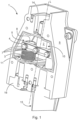
- the Figure 1 shows a perspective view of a high-performance connector system according to the invention with a horizontal section along a line parallel to the longitudinal axis of a cable connection housing 1.
- the embodiment shown has three high-performance contacts 2.
- One high-performance contact 2 is positioned opposite two identical high-performance contacts 2.
- Two high-performance contacts 2 are shown without an insulating body 3.
- the insulating body 3 accommodates the corresponding high-performance contact 2.
- the high-performance contacts 2 are connected to one another by means of an electrically conductive rail 4.
- the high-performance contacts 2 and the associated insulating body(s) 3 have recesses 5.
- the rail 4 has corresponding through-openings 6.
- the locking elements 7 shown are guided through these through-openings 6 and connected to the corresponding high-performance contacts 2.
- the locking elements 7 are screws with a hexagon screw head.
- the high-performance contacts 2 have through-holes 6, which are provided with a
- the securing elements 7 are screws with a hexagon head.
- the high-performance contacts 2 have through-holes 6 provided with an internal thread.
- a nut or similar threaded receptacle can be provided on the side opposite the rail 4.
- the high-performance contacts 2 are each designed with a blind hole provided with an internal thread.
- connection options in particular shaft-hub connections, are known to those skilled in the art and can be used as an alternative to the illustrated securing elements 7.
- the high-performance contacts 2 are aligned with their end faces 8 at least partially flush with the edge of the rail 4, which is opposite the housing opening 14 of the corresponding high-performance contact 2.
- the cable connection housing 1 has a housing wall 9. This circumferential housing wall 9 forms an interior space 10.
- the insulating body 3 shown has a profile 11, shown as an example, on the connection from a rail 4 to a housing wall 9 of the cable connection housing 1.
- the profile 11 simply and advantageously increases the clearances and creepage distances between the connection area of the rail 4 and the high-performance contact 2 shown therein.
- both the insulating body 3 and the high-performance contact 2 located therein each have a recess 5.
- This recess 5 can be formed, for example, using a machining process.
- the insulating bodies 3 are particularly ingeniously designed. These are, provided with fastening elements 12 in addition to the profiling 11.
- the fastening elements 12 are formed as basically flat, part-circular extensions on the insulating body 3.
- the housing openings 14 belonging to the insulating bodies 3 in the housing wall 9 of the cable connection housing 1 have recesses which correspond at least to the dimensions of the fastening elements 12 of the insulating bodies 3.
- the fastening elements 12 and the recesses in the housing openings 14 are positioned such that the fastening elements 12 secure them against axial displacement in the direction of the longitudinal axis L of the respective high-power contact 2 as soon as the high-power contact 2 is releasably fixed to the associated insulating body 3 and to the rail 4 by the securing element 7.
- the fastening element 12 of the insulating body 3 can be connected to the housing wall 9 in a manner comparable to a bayonet lock.
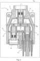
- FIG. 2 the inventive embodiment of a high-performance connector system with cable connection housing 1 is shown in a sectional view comparable to the sectional view of the Figure 1 , but shown in a direct top view.
- the Figure 1 and the Figure 2 show that the housing wall 9 has through-openings for connecting high-power connectors 15 to corresponding high-power contacts 2.
- a closure cap 16 can be inserted into the said through-openings of the cable connection housing 1 in order to both secure the insulating body 3 of the corresponding high-power contact 2 and to protect the cable connection housing 1 against the ingress of, for example, water, oil, dust or similar undesirable foreign substances.
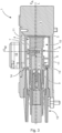
- the Figure 3 shows the embodiment of the high-performance connector system according to the invention with the cable connection housing 1 in a vertical section along the longitudinal axis L of a high-performance contact 2.
- the small spatial dimensions of the interior 10 are particularly clear in this illustration.
- the access for assembly and maintenance of the cable connection housing 1 is made clear by a housing cover 14.
- the housing cover 14 is shaped in such a way that a closure cap 16 can be connected to the housing cover 14 if the closure cap 16 is not required.
- Also clearly visible in this sectional view is the connection of the rail 4 to the high-performance contacts 2.
- the high-performance contacts 2 have a recess 5.
- the recesses 5 of the high-performance contacts 2 lie in a horizontal plane E A .
- the rail 4 can be attached to the recesses 5 in such a way that the rail 4 is flush with the respective high-performance contacts 2 at their end face 8. As a result, the high-performance contacts 2 protrude above the center plane EM of the rail 4. This embodiment achieves a small size of the cable connection housing 1 compared to the prior art.
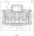
- FIG. 4 A vertical cross-section of a high-performance connector system, consisting of the cable connection housing 1 and components in the interior 10 is shown in the Figure 4 shown.
- the arrangement of the high-performance contacts 2 and the positioning of the recesses 5 in the plane E A are particularly clear here. Since the section runs along the center plane E M of the rail 4, the connections of the rail 4 with the high-performance contacts 2 by the securing elements 7 can be clearly seen.
- the securing elements 7 are aligned along their longitudinal axis parallel to the center plane E M of the rail 4, orthogonal to the plane E A . Thus, after removing the Easy maintenance access is possible via the housing cover 14.
- the fastening elements 12 of the two insulating bodies 3 of the outer high-performance contacts 2, which are designed as partially circular projections on the respective insulating body 3, are also clearly visible. After loosening and removing the rail 4 from the high-performance contacts 2, these fastening elements 12 can be aligned with corresponding recesses in the housing openings 13 by rotating the insulating bodies 3. Subsequently, as soon as the fastening elements 12 and the recesses in the housing openings 13 align, the insulating bodies 3 with the high-performance contacts 2 can be removed from the cable connection housing 1 and/or inserted and/or replaced.
Landscapes
- Engineering & Computer Science (AREA)
- Mechanical Engineering (AREA)
- Automation & Control Theory (AREA)
- Transportation (AREA)
- Connector Housings Or Holding Contact Members (AREA)
Description
- Die Erfindung geht aus von einem Hochleistungssteckverbindersystem nach der Gattung des unabhängigen Anspruchs 1.
- Derartige Hochleistungssteckverbindersysteme werden benötigt, um hohe elektrische Spannungen und hohe elektrische Ströme zu übertragen und/oder zu verteilen. Besonders liegt dabei das Augenmerk auf der Anwendbarkeit in Unterflurbereichen schienengebundener Fahrzeuge, insbesondere der Verbindung von Triebwagen und Triebwaggons untereinander.
- Im Stand der Technik sind Lösungen bekannt, welche die Übertragung und/oder Verteilung hoher elektrische Ströme und/ oder Spannung zwischen Fahrzeugen untereinander oder zwischen Fahrzeugen mit angehängten Modulen ermöglichen. Diese Lösungen sehen jedoch zumeist eine unvorteilhafte und zum Teil unlösbare Fixierung der entsprechenden Kontaktelemente vor.
- Besonders nachteilig an dem Stand der Technik ist die fehlende Wartungsfreundlichkeit und in der Regel auch ein erhöhter Platzbedarf. Grade bei stark beanspruchten Kontaktelementen, wie beispielsweise im Bereich des schienengebundenen Verkehrs wird es aufgrund immer höherer Anforderungen jedoch vermehrt zu Reparatur und Wartungsbedarf, beispielsweise durch erhöhte Elektroerosion aufgrund der hohen Stromstärken von über 500A.
- Das Deutsche Patent- und Markenamt hat in der Prioritätsanmeldung zu vorliegender Anmeldung den folgenden Stand der Technik recherchiert:
DE 41 35 391 C1 . - Die
US 2012/021650 A1 offenbart eine elektrische Verbinderanordnung, beispielsweise für Lasttrennschalter, aufweisend ein Gehäuse mit einem Sichtbereich zur Prüfung von Kontaktpositionen. - Die
US 3 845 458 A offenbart eine Stromschienenverbindungsanordnung, wobei die Verbindung der Stromschienen innerhalb eines abgedichteten Gehäuses stattfindet und wobei das innere des Verbindergehäuses mit einer Isolierflüssigkeit gefüllt ist. - Die
US 2012/018217 A1 offenbart eine Durchführungsanordnung für elektrische Steckverbinder, beispielsweise für Lasttrennschalter, wobei die der elektrische Steckverbinder mit einer Schraube in der Durchführungsanordnung fixiert werden kann, um die elektrische Verbindung zu sichern. - Die Aufgabe der Erfindung besteht darin, ein platzsparendes, sicheres und kostengünstiges Kabelanschlussgehäuse, insbesondere geeignet für die Verwendung unterflur schienengebundener Fahrzeuge, für die Übertragung und/ oder Verteilung von hohen elektrischen Strömen anzubieten.
- Die Aufgabe wird durch den Gegenstand der unabhängigen Ansprüche gelöst.
- Vorteilhafte Ausgestaltungen der Erfindung sind in den Unteransprüchen und der folgenden Beschreibung angegeben.
- Die Erfindung geht aus von einem Hochleistungssteckverbindersystem, aufweisend ein Kabelanschlussgehäuse zum Anschluss von zumindest zwei elektrischen Hochleistungssteckverbindern zur Übertragung und/ oder Verteilung hoher Stromstärken. Dabei sind die Hochleistungssteckverbinder insbesondere für Stromstärken größergleich 80 Ampere, bevorzugt Stromstärken über 500 Ampere, speziell Stromstärken im Bereich 1000 Ampere ausgelegt. Damit wird insbesondere sichergestellt, dass eine Verwendung im Bereich schienengebundener Fahrzeuge, insbesondere im Bereich unterflur von Waggons, Triebwagen und Triebwaggons möglich ist. Weiterhin nimmt das Kabelanschlussgehäuse zumindest zwei Isolierkörper auf. Die Isolierkörper sind zur Aufnahme jeweils eines Hochleistungskontaktes ausgelegt. Vorteilhafterweise verfügen die Isolierkörper über Befestigungsmittel, beispielsweise Gewinde, Fortsätze für Bajonettverschlüsse, Federn, Nuten oder ähnliche Mittel zur Fixierung des Isolierkörpers im Kabelanschlussgehäuse. Weiterhin sind die Isolierkörper zumindest im Inneren des Kabelanschlussgehäuses mit einer Profilierung oder einer Riffelung versehen, beispielsweise mit einem Wellenprofil oder radial umlaufenden Federn und/ oder Nuten. Dadurch werden die Luftstrecken und Kriechstrecken im Inneren des Kabelanschlussgehäuses vorteilhaft vergrößert. Die Längsachsen der Hochleistungskontakte sind grundsätzlich in einer Ebene angeordnet und versetzt voneinander angeordnet. Weiterhin sind die Hochleistungskontakte mittels einer elektrisch leitfähigen Schiene miteinander elektrisch leitend verbunden, wobei zur Verminderung des räumlichen Platzbedarfs die zumindest zwei Hochleistungskontakte mit einer Ausnehmung versehen sind, in welche sich die elektrisch leitende Schiene zumindest teilweise fügt. Damit kann auch eine Schiene gemeint sein, welche mit Öffnungen versehen ist, in welche die zumindest zwei Hochleistungskontakte mit der je wenigstens einen Ausnehmung eingesetzt werden. Dabei kann beispielsweise eine Verbindung bekannter Welle-Nabe Verbindungen angestrebt werden. Besonders bevorzugt wird eine Ausführungsform des Kabelanschlussgehäuses, welches mehr als zwei Hochleistungskontakte aufnimmt, insbesondere nimmt ein Kabelanschlussgehäuse drei Hochleistungskontakte auf. Der Hochleistungskontakt ist bevorzugt wenigstens teilweise als zylindrisches Profil ausgeführt. Besonders bevorzugt ist zumindest ein zu verbindender Bereich des Hochleistungskontaktes als zylindrisches Vollprofil ausgeformt. Die Verwendung anderer geometrischer Profile sind dem Fachmann bekannt und können vorteilhaft eingesetzt werden. Der zylindrische Hochleistungskontakt weist bevorzugt in einem Bereich der Umfangsfläche einen grundsätzlich planen Bereich auf, welcher zur Verbindung mit der elektrisch leitenden Schiene vorgesehen ist. Dieser plane Bereich kann beispielsweise spanend abgetragen sein, insbesondere durch Fräsen. Weiterhin könnte auf zerspanende Weise auch eine Nut in den Hochleistungskontakt eingearbeitet werden. Die Nut sollte dabei idealerweise eine Tiefe erreichen die ausreichend ist, die elektrisch leitende Schiene wenigstens teilweise aufzunehmen. Durch die Verbindung der Schiene mit den Hochleistungskontakten, sei es durch plane Auflagefläche oder eingearbeitete Nut, kann zunächst räumlich Platz eingespart werden. Darüber hinaus wird verhindert, dass sich die Hochleistungskontakte innerhalb der die Hochleistungskontakt aufnehmenden Isolierkörper um ihre Längsachse verdrehen. Grundsätzlich sind auch umformende Fertigungsverfahren zur Herstellung einer etwa planen Fläche am Hochleistungskontakt denkbar. Die Ausnehmungen der zumindest zwei Hochleistungskontakte liegen in etwa in einer Ebene, sodass die Schiene auf den Ausnehmungen aufliegend befestigt ist. Somit wird sowohl die Rotation der Hochleistungskontakte als auch ein axiales Verschieben in Richtung der Längsachse der Hochleistungskontakte verhindert. Das Kabelanschlussgehäuse und die daran befestigten Isolierkörper nehmen dabei grundsätzlich die in Längsrichtung der Hochleistungskontakte wirkenden Kräfte auf. Durch die Schiene werden die Hochleistungskontakte weiterhin sowohl in Längsrichtung gesichert, als auch gegen verdrehen um die Längsachse gesichert. Die Hochleistungskontakte ragen von einer Gehäusewand des Hochleistungssteckverbinders in einen Innenraum des Kabelanschlussgehäuses, wobei die Hochleistungskontakte im Innenraum freistehend positioniert sind und von der Schiene arretiert sind. Die Isolierkörper sind dazu derart ausgeführt, dass Sie mit dem Kabelanschlussgehäuse grundsätzlich lösbar verbunden sind. Idealerweise werden die Isolierkörper mit Schraubverbindungen an das Kabelanschlussgehäuse montiert. Geschickter Weise werden die Isolierkörper durch eine Durchgangsöffnung geführt und an dieser im Kabelanschlussgehäuse fixiert. Ein Hochleistungssteckverbinder ist dabei derart ausgeführt, dass dieser lösbar mit dem Kabelanschlussgehäuse fixiert werden kann. Dabei ist der Hochleistungssteckverbinder idealerweise mit einem eigenen Gehäuse ausgestattet, welches sich formschlüssig in das Kabelanschlussgehäuse fügen lässt, und mit Sicherungselementen, beispielsweise Schrauben, lösbar an dem Kabelanschlussgehäuse befestigen lässt. Durch diese Ausgestaltung können alle im Kabelanschlussgehäuse auftretenden Kräfte durch den Hochleistungssteckverbinder sowie das Kabelanschlussgehäuse selbst aufgenommen und abgefangen werden, sodass die Schiene mit den Hochleistungskontakten problemlos innerhalb des Kabelanschlussgehäuses ohne weitere Halteelemente auskommt. Besonders vorteilhaft sind hierbei Isolierkörper mit einer zuvor erwähnten Profilierung ausgeführt, beispielsweise mit grundsätzlich wellenförmigen Ausformungen, quer zur Längsachse. Die freistehenden Isolierkörper mitsamt der erwähnten Profilierung wirken sich hervorragend auf die einzuhaltenden Luftstrecken und Kriechstrecken aus.
- In einer bevorzugten Ausführungsform ist die Schiene formschlüssig mit den Hochleistungskontakten verbunden. Eine Schiene kann beispielsweise über mehrere gleichartige erste Öffnungen verfügen, in welche die Hochleistungskontakte eingeschoben werden. Diese Öffnungen werden gemäß der Erfindung grundsätzlich als zylindrische Öffnungen ausgeführt, allerdings mit angeformten Fortsätzen, welche mit den Ausnehmungen der korrelierenden Hochleistungskontakte in Eingriff gebracht werden. Um die Schiene mit den Hochleistungskontakten zu verbinden kann nun beispielsweise ein Sicherungsstift, ein Splint oder ein vergleichbares Sicherungselement durch die jeweiligen Hochleistungskontakte gesteckt werden. Ebenfalls kann eine zweite Öffnung in der Schiene vorgesehen sein, welche grundsätzlich etwa orthogonal zu einer ersten Öffnung verläuft und mit einer korrespondierenden Öffnung in den jeweiligen Hochleistungskontakten in Übereinstimmung gebracht werden können. Durch diese zweite Öffnung kann ein Sicherungselement eingebracht werden, um eine formschlüssige Sicherung zu erreichen. Dabei ist die zweite Öffnung in der Schiene sowohl als Durchgangsöffnung wie auch als Sackloch ausführbar.
- In einer besonders bevorzugten Ausführungsform ist die Schiene kraftschlüssig mit den Hochleistungskontakten verbunden. Dazu liegt die Schiene beispielsweise auf den Ausnehmungen der Hochleistungskontakte auf. Als Sicherungselement können verschiedene kraftschlüssige Sicherungselemente eingesetzt werden, beispielsweise Keile, Schrauben, Madenschrauben, Gewindebolzen oder Nieten. In einer Ausführungsform weist die Schiene je Hochleistungskontakt zumindest eine Durchgangsöffnung auf, durch welche zumindest ein Sicherungselement mit Außengewinde geführt ist, wobei das Sicherungselement mit einem Innengewinde im Hochleistungskontakt verbunden ist. Bevorzugt werden Schrauben durch die Durchgangsöffnungen in der Schiene eingeführt und in eine Gewindeöffnung in einem korrespondierenden Hochleistungskontakt eingeschraubt. Bei der Gewindeöffnung kann es sich um ein Sackloch handeln. Ebenso kann es sich um eine Durchgangsöffnung mit Gewinde handeln.
- In einer sinnvollen Ausführungsform sind die zumindest zwei Hochleistungskontakte sich gegenüberliegend im Kabelanschlussgehäuse angeordnet. Da die Hochleistungskontakte im Kabelanschlussgehäuse verbunden werden, können die Hochleistungskontakte sich kontaktieren. Die erfindungsgemäße Schiene sorgt für die sichere Kontaktierung der zumindest zwei Hochleistungskontakte. Besonders bevorzugt wird eine Ausführungsform mit zumindest drei Hochleistungskontakten, welche sich im Kabelanschlussgehäuse durch die Schiene elektrisch leitend verbinden lassen. Dabei liegen sich zumindest ein Hochleistungskontakt und die zumindest zwei verbleibenden Hochleistungskontakte gegenüber. Die Schiene wird dabei parallel zu einer durch die Längsachsen der Hochleistungskontakte gebildete Ebene mit den Hochleistungskontakten verbunden. In einer Ausführungsform liegen die Längsachsen der Hochleistungskontakte grundsätzlich parallel zueinander. Die Schiene wird in dieser Ausführungsform parallel zu der durch die Längsachsen der Hochleistungskontakte gebildete Ebene und zumindest grundsätzlich orthogonal zu den Längsachsen der Hochleistungskontakte ausgerichtet.
- In einer vorteilhaften Ausführungsform weist die Schiene eine vertikale Mittelebene auf, welche von jedem der zumindest zwei Hochleistungskontakte zumindest teilweise durchstoßen wird. Durch diese Ausführungsform wird sichergestellt, dass die Schiene genug Auflagefläche, bzw. Kontaktfläche mit den Hochleistungskontakten aufbringen kann. Ein weiterer Vorteil besteht darin, dass beispielsweise bei dem Einsatz von zumindest drei Hochleistungskontakten die Längsachsen der gegenüberliegenden Hochleistungskontakte versetzt zueinander, parallel in einer gemeinsamen horizontalen Ebene positioniert werden. Dadurch wird eine besonders platzsparende Bauform erreicht, da die Hochleistungskontakte nicht vor ein Halteelement oder eine Schiene stoßen, sondern an der Schiene vorbei oder durch die Schiene geführt werden. Da es grundsätzlich darum geht, Spannungen und Ströme zu übertragen, können auch hier die Hochleistungskontakte dicht nebeneinander positioniert werden.
- Eine logische Ausführungsform sieht demnach vor, die Schiene zumindest größtenteils bündig mit den Stirnflächen der zumindest zwei Hochleistungskontakte zu verbinden. Damit ist gemäß zuvor genannter Ausführungsform gemeint, dass die Hochleistungskontakte über die Mittelebene der Schiene hinaus bis an die entsprechende Kante der Schiene geführt sind. Dadurch wird eine sichere Kontaktierung der Schiene zu den zumindest zwei Hochleistungskontakten bewirkt.
- Eine besonders wartungsfreundliche Ausführungsform sieht entsprechend vor, die Sicherungselemente orthogonal zu der Mittelebene der Schiene auszurichten. Das Kabelanschlussgehäuse des Hochleistungssteckverbinders wird mit einem Gehäusedeckel zur idealerweise luftdichten und wasserdichten Abschottung des Innenraums des Kabelanschlussgehäuses versehen. Wird der Gehäusedeckel entfernt, können zu Reparaturzwecken oder zu Wartungszwecken die vom Gehäusedeckel in Richtung Boden des Kabelanschlussgehäuses gerichteten Sicherungselemente, bei denen es sich idealerweise um Schrauben handelt, einfach von Wartungspersonal erreicht werden. Dabei sei erwähnt, dass der Gehäusedeckel des Kabelanschlussgehäuses sinnvollerweise in Richtung Erdboden gerichtet ist, während der Boden des Kabelanschlussgehäuses außen unterflur an einem Fahrzeug, beispielsweise einem Triebwagen, oder einem durch ein Fahrzeug bewegbares, angehängtes Transportelement, beispielsweise einem Waggon, angebracht wird. Somit kann das Wartungspersonal oder das Reparaturpersonal in einfacher Weise Zugang zu dem Innenraum des Kabelanschlussgehäuses, insbesondere zu den Hochleistungskontakten und/ oder der Schiene erhalten.
- Ein Ausführungsbeispiel der Erfindung ist in den Zeichnungen dargestellt und wird im Folgenden näher erläutert. Es zeigen:
- Fig. 1
- ein Teilschnitt einer perspektivischen Darstellung eines erfindungsgemäßen Hochleistungssteckverbindersystems;
- Fig. 2
- ein horizontaler Schnitt entlang einer Längsachse des erfindungsgemäßen Hochleistungssteckverbindersystems;
- Fig. 3
- ein vertikaler Schnitt entlang einer Längsachse des erfindungsgemäßen Hochleistungssteckverbindersystems;
- Fig. 4
- ein Querschnitt entlang einer Schiene des erfindungsgemäßen Hochleistungssteckverbindersystems.
- Die Figuren enthalten teilweise vereinfachte, schematische Darstellungen. Zum Teil werden für gleiche, aber gegebenenfalls nicht identische Elemente identische Bezugszeichen verwendet. Verschiedene Ansichten gleicher Elemente könnten unterschiedlich skaliert sein.
- Richtungsangaben wie beispielsweise "links", "rechts", "oben" und "unten" sind mit Bezug auf die jeweilige Figur zu verstehen und können in den einzelnen Darstellungen gegenüber dem dargestellten Objekt variieren.
- Die
Figur 1 zeigt eine perspektivische Darstellung eines erfindungsgemäßen Hochleistungssteckverbindersystems mit horizontalen Schnitt entlang einer Parallelen zur Längsachse eines Kabelanschlussgehäuse 1. Die dargestellte Ausführungsform weist drei Hochleistungskontakte 2 auf. Dabei ist ein Hochleistungskontakt 2 zwei baugleichen Hochleistungskontakten 2 gegenüberliegend positioniert. Zwei Hochleistungskontakte 2 sind ohne einen Isolierkörper 3 dargestellt. Der Isolierkörper 3 nimmt den entsprechenden Hochleistungskontakt 2 in sich auf. Die Hochleistungskontakte 2 sind mittels einer elektrisch leitenden Schiene 4 miteinander verbunden. Dazu weisen die Hochleistungskontakte 2, sowie die dazugehörige(n) Isolierkörper 3 Ausnehmungen 5 auf. Die Schiene 4 weist entsprechende Durchgangsöffnungen 6 auf. Durch diese Durchgangsöffnungen 6 werden die dargestellten Sicherungselemente 7 geführt und mit den korrespondierenden Hochleistungskontakten 2 verbunden. In der dargestellten Ausführung handelt es sich bei den Sicherungselementen 7 um Schrauben mit Sechskant Schraubenkopf. Zur Verschraubung von Schiene 4 und Hochleistungskontakt 2, weisen die Hochleistungskontakte 2 Durchgangsöffnungen 6 auf, welche mit einem dargestellten Ausführung handelt es sich bei den Sicherungselementen 7 um Schrauben mit Sechskant Schraubenkopf. Zur Verschraubung von Schiene 4 und Hochleistungskontakt 2, weisen die Hochleistungskontakte 2 Durchgangsöffnungen 6 auf, welche mit einem Innengewinde versehen sind. Anstelle eines Gewindes in den Durchgangsöffnungen 6 können auf der der Schiene 4 gegenüberliegenden Seite eine Mutter oder vergleichbare Gewindeaufnahme nachfolgen. Alternativ werden die Hochleistungskontakte 2 mit je einem Sackloch ausgeführt, welches mit einem Innengewinde versehen ist. Andere Verbindungsmöglichkeiten, insbesondere Welle-Nabe Verbindungen, sind dem Fachmann bekannt und können alternativ zu den dargestellten Sicherungselementen 7 zu einem Einsatz kommen. Zur Herstellung einer sicheren und zumindest ausreichenden elektrischen Verbindung werden die Hochleistungskontakte 2 mit deren Stirnseiten 8 zumindest teilweise bündig mit der Kante der Schiene 4 in Flucht gebracht, welche dem Gehäusedurchbruch 14 des entsprechenden Hochleistungskontakts 2 gegenüberliegt. Das Kabelanschlussgehäuse 1 weist eine Gehäusewand 9 auf. Diese umlaufende Gehäusewand 9 bildet einen Innenraum 10. - Der dargestellte Isolierkörper 3 weist an der von einer Schiene 4 zu einer Gehäusewand 9 des Kabelanschlussgehäuses 1 eine Profilierung 11 auf, welche beispielhaft dargestellt ist. Die Profilierung 11 erhöht in einfacher und vorteilhafter Weise die Luftstrecken und Kriechstrecken vom Anschlussbereich der Schiene 4 und dem darin dargestellten Hochleistungskontakt 2. Weiterhin ist erkennbar, dass sowohl der Isolierkörper 3, als auch der darin befindliche Hochleistungskontakt 2 über je eine Ausnehmung 5 verfügen. Diese Ausnehmung 5 kann beispielsweise mittels spanendem Herstellungsverfahren ausgeformt werden. Besonders trickreich sind die Isolierkörper 3 gestaltet. Diese sind, neben der Profilierung 11 mit Befestigungselementen 12 versehen. Die Befestigungselemente 12 sind als grundsätzlich plane, teilkreisförmige Fortsätze an dem Isolierkörper 3 angeformt. Die zu den Isolierkörpern 3 gehörenden Gehäusedurchbrüche 14 in der Gehäusewand 9 des Kabelanschlussgehäuses 1 weisen Ausnehmungen auf, welche zumindest den Ausmaßen der Befestigungselemente 12 der Isolierkörper 3 entsprechen. Dabei sind die Befestigungselemente 12 und die Ausnehmungen in den Gehäusedurchbrüchen 14 derart positioniert, dass die Befestigungselemente 12 eine Sicherung gegen axiales Verschieben in Richtung der Längsachse L des jeweiligen Hochleistungskontakts 2 herstellen, sobald der Hochleistungskontakt 2 mit dem dazugehörigen Isolierkörper 3 und mit der Schiene 4 durch das Sicherungselement 7 lösbar fixiert ist. Anders formuliert, lässt sich das Befestigungselement 12 des Isolierkörpers 3 vergleichbar mit einem Bajonettverschluss mit der Gehäusewand 9 verbinden.
- In der
Figur 2 wird die erfindungsgemäße Ausführungsform eines Hochleistungssteckverbindersystems mit Kabelanschlussgehäuse 1 in einer Schnittdarstellung vergleichbar der Schnittdarstellung derFigur 1 , jedoch in einer direkten Draufsicht gezeigt. DieFigur 1 und dieFigur 2 zeigen, dass die Gehäusewand 9 Durchgangsöffnungen zum Anschluss von Hochleistungssteckverbindern 15 an korrespondierende Hochleistungskontakte 2 aufweist. Sofern jedoch ein Kabelanschlussgehäuse 1 nur zwei Hochleistungskontakte 2 aufnimmt, kann eine Verschlusskappe 16 in die besagten Durchgangsöffnungen des Kabelanschlussgehäuses 1 eingesetzt werden, um sowohl den Isolierkörper 3 des entsprechenden Hochleistungskontakts 2 zu sichern, als auch das Kabelanschlussgehäuse 1 gegen das Eindringen von beispielsweise Wasser, Öl, Staub oder ähnlichen unerwünschten Fremdsubstanzen zu schützen. - Die
Figur 3 zeigt die erfindungsgemäße Ausführungsform des Hochleistungssteckverbindersystems mit dem Kabelanschlussgehäuse 1 in einem vertikalen Schnitt entlang der Längsachse L eines Hochleistungskontaktes 2. Besonders deutlich in dieser Darstellung wird die geringe räumliche Dimensionierung des Innenraums 10. Darüber hinaus wird der Zugang zur Montage und Wartung des Kabelanschlussgehäuses 1 durch einen Gehäusedeckel 14 deutlich. Der Gehäusedeckel 14 ist dabei derart ausgeformt, dass eine Verschlusskappe 16 mit dem Gehäusedeckel 14 verbunden werden kann, sofern die Verschlusskappe 16 nicht benötigt wird. Ebenfalls gut erkenntlich wird in dieser Schnittdarstellung die Verbindung der Schiene 4 mit den Hochleistungskontakten 2. Die Hochleistungskontakte 2 weisen eine Ausnehmung 5 auf. Die Ausnehmungen 5 der Hochleistungskontakte 2 liegen dazu in einer horizontalen Ebene EA. Die Schiene 4 lässt sich auf die Ausnehmungen 5 derart aufbringen, dass die Schiene 4 mit den jeweiligen Hochleistungskontakten 2 an deren Stirnseite 8 bündig abschließt. Dadurch bedingt ragen die Hochleistungskontakte 2 über die Mittelebene EM der Schiene 4 hervor. Durch diese Ausführungsform wird eine, im Vergleich zu dem Stand der Technik, geringe Baugröße des Kabelanschlussgehäuses 1 erreicht. - Ein vertikaler Querschnitt eines Hochleistungssteckverbindersystems, bestehend aus dem Kabelanschlussgehäuse 1 und Bauteilen im Innenraum 10 wird in der
Figur 4 dargestellt. Besonders deutlich wird hier die Anordnung der Hochleistungskontakte 2 und die Positionierung der Ausnehmungen 5 in der Ebene EA. Da der Schnitt entlang der Mittelebene EM der Schiene 4 verläuft, lassen sich die Verbindungen der Schiene 4 mit den Hochleistungskontakten 2 durch die Sicherungselemente 7 gut erkennen. Die Sicherungselemente 7 sind dabei entlang ihrer Längsachse parallel zur Mittelebene EM der Schiene 4 ausgerichtet, orthogonal zur Ebene EA. Somit kann nach entfernen des Gehäusedeckels 14 ein einfacher Wartungszugriff erfolgen. Sehr gut zu erkennen sind auch die Befestigungselemente 12 der zwei Isolierkörper 3 der äußeren Hochleistungskontakte 2, welche als Teilkreisförmige Anformungen am jeweiligen Isolierkörper 3 ausgeführt sind. Diese Befestigungselemente 12 können nach dem Lösen und Entfernen der Schiene 4 von den Hochleistungskontakten 2 durch verdrehen der Isolierkörper 3 mit übereinstimmenden Ausnehmungen in den Gehäusedurchbrüchen 13 in Flucht gebracht werden. Anschließend, sobald die Befestigungselemente 12 und die Ausnehmungen in den Gehäusedurchbrüchen 13 übereinstimmen, können die Isolierkörper 3 mit den Hochleistungskontakten 2 aus dem Kabelanschlussgehäuse 1 entfernt und/ oder eingesetzt und/ oder ausgetauscht werden. - Auch wenn in den Figuren verschiedene Aspekte oder Merkmale der Erfindung jeweils in Kombination gezeigt sind, ist für den Fachmann - soweit nicht anders angegeben - ersichtlich, dass die dargestellten und diskutierten Kombinationen nicht die einzig möglichen sind. Insbesondere können einander entsprechende Einheiten oder Merkmalskomplexe aus unterschiedlichen Ausführungsbeispielen miteinander ausgetauscht werden.
-
- 1
- Kabelanschlussgehäuse
- 2
- Hochleistungskontakt
- 3
- Isolierkörper
- 4
- Schiene
- 5
- Ausnehmung
- 6
- Durchgangsöffnung
- 7
- Sicherungselement
- 8
- Stirnfläche
- 9
- Seitenwand
- 10
- Innenraum
- 11
- Profilierung
- 12
- Befestigungselement
- 13
- Gehäusedurchbruch
- 14
- Gehäusedeckel
- 15
- Hochleistungssteckverbinder
- 16
- Verschlusskappe
- L
- Längsachse
- EA
- Ebene
- EM
- Mittelebene
Claims (9)
- Hochleistungssteckverbindersystem aufweisend ein Kabelanschlussgehäuse (1), zum Anschluss von zumindest zwei elektrischen Hochleistungssteckverbindern (15) zur Übertragung und/ oder Verteilung hoher elektrischer Stromstärken und/ oder hohen elektrischen Spannungen, zumindest zwei Isolierkörper (3) zur Aufnahme zumindest je eines Hochleistungskontakts (2) und zumindest einer elektrisch leitfähigen Schiene (4), wobei die Längsachsen (L) der Hochleistungskontakte (2) grundsätzlich in einer Ebene und versetzt voneinander angeordnet sind und wobei die Hochleistungskontakte (2) mittels einer elektrisch leitfähigen Schiene (4) miteinander elektrisch leitend verbunden sind, wobei die zumindest zwei Hochleistungskontakte (2) mit zumindest einer Ausnehmung (5) versehen sind, in welche sich die elektrisch leitende Schiene (4) zumindest teilweise fügt,
dadurch gekennzeichnet, dass
die Ausnehmungen (5) der zumindest zwei Hochleistungskontakte (2) in etwa in einer Ebene (EA) liegen, sodass die Schiene (4) auf den Ausnehmungen (5) aufliegend befestigt ist und somit sowohl radiales Verdrehen als auch ein axiales Verschieben in Richtung der Längsachse (L) der Hochleistungskontakte (2) verhindert und wobei die Hochleistungskontakte (2) in den dazugehörigen Isolierkörpern (3) von einer Gehäusewand (9) des Kabelanschlussgehäuses (1) in einen Innenraum (10) des Kabelanschlussgehäuses (1) ragen, wobei die Hochleistungskontakte (2) im Innenraum (10) freistehend positioniert sind und von der Schiene (4) arretiert sind. - Hochleistungssteckverbindersystem nach Anspruch 1
dadurch gekennzeichnet, dass
die Schiene (4) formschlüssig mit den Hochleistungskontakten (2) verbunden ist. - Hochleistungssteckverbindersystem nach Anspruch 1
dadurch gekennzeichnet, dass
die Schiene (4) kraftschlüssig mit den Hochleistungskontakten (2) verbunden ist. - Hochleistungssteckverbindersystem nach einem der vorstehenden Ansprüche
dadurch gekennzeichnet, dass
die Schiene (4) je Hochleistungskontakt (2) zumindest eine Durchgangsöffnung (6) aufweist, durch welche zumindest ein Sicherungselement (7) mit Außengewinde geführt ist, wobei das Sicherungselement (7) mit einem Innengewinde im Hochleistungskontakt (2) verbunden ist. - Hochleistungssteckverbindersystem nach einem der vorstehenden Ansprüche
dadurch gekennzeichnet, dass
zumindest ein Hochleistungskontakt (2) dem verbleibenden, zumindest einen Hochleistungskontakt (2) gegenüberliegend im Kabelanschlussgehäuse (1) angeordnet ist. - Hochleistungssteckverbindersystem nach einem der vorstehenden Ansprüche
dadurch gekennzeichnet, dass
die Schiene (4) eine vertikale Mittelebene (EM) aufweist, welche von jedem Hochleistungskontakt (2) zumindest teilweise durchstoßen wird. - Hochleistungssteckverbindersystem nach einem der vorstehenden Ansprüche
dadurch gekennzeichnet, dass
die Schiene (4) zumindest größtenteils bündig mit den Stirnflächen (8) der zumindest zwei Hochleistungskontakte (2) verbunden ist. - Hochleistungssteckverbindersystem nach einem der Ansprüche 4 bis 7,
dadurch gekennzeichnet, dass
die Sicherungselemente (7) Parallel zu der Mittelebene (EM) der Schiene (4) ausgerichtet sind. - Hochleistungssteckverbindersystem aufweisend ein Kabelanschlussgehäuse (1), zum Anschluss von zumindest zwei elektrischen Hochleistungssteckverbindern (15) zur Übertragung und/ oder Verteilung hoher elektrischer Stromstärken und/ oder hohen elektrischen Spannungen, zumindest zwei Isolierkörper (3) zur Aufnahme zumindest je eines Hochleistungskontakts (2) und zumindest einer elektrisch leitfähigen Schiene (4), wobei die Längsachsen (L) der Hochleistungskontakte (2) grundsätzlich in einer Ebene und versetzt voneinander angeordnet sind und wobei die Hochleistungskontakte (2) mittels einer elektrisch leitfähigen Schiene (4) miteinander elektrisch leitend verbunden sind, wobei die zumindest zwei Hochleistungskontakte (2) mit zumindest einer Ausnehmung (5) versehen sind, in welche sich die elektrisch leitende Schiene (4) zumindest teilweise fügt,
dadurch gekennzeichnet, dass
die Isolierkörper (3) die Hochleistungskontakte (2) derart aufnehmen, dass die Hochleistungskontakte (2) und die Schiene (4) sich im miteinander verbundenen Zustand gegenseitig im Innenraum (10) halten, wobei die Schiene nur die Hochleistungskotakte (2) kontaktiert.
Applications Claiming Priority (2)
| Application Number | Priority Date | Filing Date | Title |
|---|---|---|---|
| DE102020108457.9A DE102020108457A1 (de) | 2020-03-27 | 2020-03-27 | Hochleistungssteckverbindersystem |
| PCT/DE2021/100296 WO2021190707A1 (de) | 2020-03-27 | 2021-03-25 | Hochleistungssteckverbindersystem |
Publications (2)
| Publication Number | Publication Date |
|---|---|
| EP4128443A1 EP4128443A1 (de) | 2023-02-08 |
| EP4128443B1 true EP4128443B1 (de) | 2025-04-30 |
Family
ID=75539038
Family Applications (1)
| Application Number | Title | Priority Date | Filing Date |
|---|---|---|---|
| EP21719041.2A Active EP4128443B1 (de) | 2020-03-27 | 2021-03-25 | Hochleistungssteckverbindersystem |
Country Status (6)
| Country | Link |
|---|---|
| US (1) | US12249797B2 (de) |
| EP (1) | EP4128443B1 (de) |
| KR (1) | KR102709621B1 (de) |
| CN (1) | CN115336117B (de) |
| DE (1) | DE102020108457A1 (de) |
| WO (1) | WO2021190707A1 (de) |
Families Citing this family (1)
| Publication number | Priority date | Publication date | Assignee | Title |
|---|---|---|---|---|
| WO2023148085A1 (de) * | 2022-02-03 | 2023-08-10 | Hirschmann Automotive Gmbh | Steckverbinder mit zumindest einem sicherungssplint |
Family Cites Families (11)
| Publication number | Priority date | Publication date | Assignee | Title |
|---|---|---|---|---|
| GB1104717A (en) * | 1965-07-06 | 1968-02-28 | Molex Products Co | Push type connectors and terminal boards |
| JPS5237594B2 (de) * | 1972-08-22 | 1977-09-22 | ||
| DE3482357D1 (de) * | 1983-12-14 | 1990-06-28 | Raychem Ltd | Hochspannungsverbinder. |
| US4799895A (en) * | 1987-06-22 | 1989-01-24 | Amerace Corporation | 600-Amp hot stick operable screw-assembled connector system |
| DE4135391C1 (en) | 1991-10-26 | 1992-12-10 | Karl Pfisterer Elektrotechnische Spezialartikel Gmbh & Co Kg, 7000 Stuttgart, De | Cable connector for medium high voltage and high current - has socket with cup-shaped contact element, and cylindrical insulating housing covering inserted cable |
| US8641434B2 (en) | 2010-07-21 | 2014-02-04 | Thomas & Betts International, Inc | Rotatable feedthru insert |
| US8388381B2 (en) * | 2010-07-21 | 2013-03-05 | Thomas & Betts International, Inc. | Visible open for switchgear assembly |
| DE102011001714A1 (de) * | 2011-03-31 | 2012-10-04 | Phoenix Contact Gmbh & Co. Kg | Querbrücker für eine elektrische Klemme |
| US8292651B1 (en) * | 2011-06-09 | 2012-10-23 | Bae Systems Land & Armaments, L.P. | High voltage connector with a ring assembly to force a plug axially into a header assembly |
| WO2013152261A1 (en) * | 2012-04-05 | 2013-10-10 | Molex Incorporated | High power electrical connector |
| DE202018100223U1 (de) * | 2017-01-30 | 2018-01-24 | Lisa Dräxlmaier GmbH | Hochvoltsteckverbinder |
-
2020
- 2020-03-27 DE DE102020108457.9A patent/DE102020108457A1/de active Pending
-
2021
- 2021-03-25 WO PCT/DE2021/100296 patent/WO2021190707A1/de not_active Ceased
- 2021-03-25 KR KR1020227037097A patent/KR102709621B1/ko active Active
- 2021-03-25 US US17/909,380 patent/US12249797B2/en active Active
- 2021-03-25 CN CN202180024089.3A patent/CN115336117B/zh active Active
- 2021-03-25 EP EP21719041.2A patent/EP4128443B1/de active Active
Also Published As
| Publication number | Publication date |
|---|---|
| DE102020108457A1 (de) | 2021-09-30 |
| KR20220159424A (ko) | 2022-12-02 |
| CN115336117B (zh) | 2026-01-09 |
| CN115336117A (zh) | 2022-11-11 |
| US20230096306A1 (en) | 2023-03-30 |
| KR102709621B1 (ko) | 2024-09-26 |
| US12249797B2 (en) | 2025-03-11 |
| EP4128443A1 (de) | 2023-02-08 |
| WO2021190707A1 (de) | 2021-09-30 |
Similar Documents
| Publication | Publication Date | Title |
|---|---|---|
| DE102008017423B4 (de) | Überspannungsschutzgerät | |
| EP3561322A1 (de) | Befestigungssystem zum befestigen von einbauelementen in einer kabine eines fahrzeugs | |
| DE102020108458A1 (de) | Hochleistungssteckverbindersystem | |
| EP2559107B1 (de) | Hauptleiteranschlussklemme | |
| EP2690314B1 (de) | Spindelantrieb | |
| DE102019109725B4 (de) | Batteriemodul und System aus Batterieverbinder und Batteriemodulen | |
| EP4128443B1 (de) | Hochleistungssteckverbindersystem | |
| DE102009057854A1 (de) | Elektrische Klemme, insbesondere Reihenklemme, mit einem Gehäuse und einer an dem Gehäuse gehaltenen Stromschiene | |
| WO2015131875A1 (de) | Befestigungselement für einen stromsensor | |
| EP4209383A1 (de) | Batteriegehäuse für eine fahrzeugbatterie und fahrzeugbatterie | |
| WO2022022776A1 (de) | Hochleistungssteckverbindersystem | |
| WO2020193805A1 (de) | Batterieanordnung | |
| EP4168285B1 (de) | Hochleistungssteckverbindersystem | |
| EP4150725B1 (de) | Anbaugehäuse für hochleistungssteckverbinder | |
| EP3607615B1 (de) | Halterahmen | |
| AT521473B1 (de) | Batteriemodul | |
| DE4225989C2 (de) | Feldabstandhalter für Hochspannungs-Freileitungen mit Bündelleitern | |
| EP1381118A1 (de) | Symmetrischer Steckverbinder | |
| DE4202331C2 (de) | Schutzvorrichtung für Kabelsteckteile in T- oder Winkelform | |
| DE29610554U1 (de) | Elektrisches Installationsgerät insbesondere zur Aufputz-Montage | |
| EP4713995A1 (de) | Gehäuse für einen modulpolanschluss zur bereitstellung eines berührschutzes, modulpolanschluss, verbindungsanordnung und batteriemodul für ein kraftfahrzeug | |
| DE102024002546A1 (de) | Klemmvorrichtung | |
| DE102014209502B4 (de) | Trägereinheit | |
| DE102005032092B4 (de) | Kondensatormodul | |
| DE19904949C1 (de) | Abgangsschienenträger zum Einbau in eine elektrische Verteilanlage |
Legal Events
| Date | Code | Title | Description |
|---|---|---|---|
| STAA | Information on the status of an ep patent application or granted ep patent |
Free format text: STATUS: UNKNOWN |
|
| STAA | Information on the status of an ep patent application or granted ep patent |
Free format text: STATUS: THE INTERNATIONAL PUBLICATION HAS BEEN MADE |
|
| PUAI | Public reference made under article 153(3) epc to a published international application that has entered the european phase |
Free format text: ORIGINAL CODE: 0009012 |
|
| STAA | Information on the status of an ep patent application or granted ep patent |
Free format text: STATUS: REQUEST FOR EXAMINATION WAS MADE |
|
| 17P | Request for examination filed |
Effective date: 20220818 |
|
| AK | Designated contracting states |
Kind code of ref document: A1 Designated state(s): AL AT BE BG CH CY CZ DE DK EE ES FI FR GB GR HR HU IE IS IT LI LT LU LV MC MK MT NL NO PL PT RO RS SE SI SK SM TR |
|
| DAV | Request for validation of the european patent (deleted) | ||
| DAX | Request for extension of the european patent (deleted) | ||
| P01 | Opt-out of the competence of the unified patent court (upc) registered |
Effective date: 20230603 |
|
| GRAP | Despatch of communication of intention to grant a patent |
Free format text: ORIGINAL CODE: EPIDOSNIGR1 |
|
| STAA | Information on the status of an ep patent application or granted ep patent |
Free format text: STATUS: GRANT OF PATENT IS INTENDED |
|
| RIC1 | Information provided on ipc code assigned before grant |
Ipc: H02G 15/16 20060101ALN20241024BHEP Ipc: H01R 31/02 20060101ALI20241024BHEP Ipc: H01R 25/00 20060101ALI20241024BHEP Ipc: H01R 13/53 20060101AFI20241024BHEP |
|
| RIC1 | Information provided on ipc code assigned before grant |
Ipc: H02G 15/16 20060101ALN20241030BHEP Ipc: H01R 31/02 20060101ALI20241030BHEP Ipc: H01R 25/00 20060101ALI20241030BHEP Ipc: H01R 13/53 20060101AFI20241030BHEP |
|
| INTG | Intention to grant announced |
Effective date: 20241122 |
|
| GRAS | Grant fee paid |
Free format text: ORIGINAL CODE: EPIDOSNIGR3 |
|
| GRAA | (expected) grant |
Free format text: ORIGINAL CODE: 0009210 |
|
| STAA | Information on the status of an ep patent application or granted ep patent |
Free format text: STATUS: THE PATENT HAS BEEN GRANTED |
|
| AK | Designated contracting states |
Kind code of ref document: B1 Designated state(s): AL AT BE BG CH CY CZ DE DK EE ES FI FR GB GR HR HU IE IS IT LI LT LU LV MC MK MT NL NO PL PT RO RS SE SI SK SM TR |
|
| REG | Reference to a national code |
Ref country code: CH Ref legal event code: EP Ref country code: GB Ref legal event code: FG4D Free format text: NOT ENGLISH |
|
| REG | Reference to a national code |
Ref country code: DE Ref legal event code: R096 Ref document number: 502021007345 Country of ref document: DE |
|
| REG | Reference to a national code |
Ref country code: IE Ref legal event code: FG4D Free format text: LANGUAGE OF EP DOCUMENT: GERMAN |
|
| REG | Reference to a national code |
Ref country code: NL Ref legal event code: MP Effective date: 20250430 |
|
| PG25 | Lapsed in a contracting state [announced via postgrant information from national office to epo] |
Ref country code: FI Free format text: LAPSE BECAUSE OF FAILURE TO SUBMIT A TRANSLATION OF THE DESCRIPTION OR TO PAY THE FEE WITHIN THE PRESCRIBED TIME-LIMIT Effective date: 20250430 Ref country code: ES Free format text: LAPSE BECAUSE OF FAILURE TO SUBMIT A TRANSLATION OF THE DESCRIPTION OR TO PAY THE FEE WITHIN THE PRESCRIBED TIME-LIMIT Effective date: 20250430 Ref country code: PT Free format text: LAPSE BECAUSE OF FAILURE TO SUBMIT A TRANSLATION OF THE DESCRIPTION OR TO PAY THE FEE WITHIN THE PRESCRIBED TIME-LIMIT Effective date: 20250901 |
|
| REG | Reference to a national code |
Ref country code: LT Ref legal event code: MG9D |
|
| PG25 | Lapsed in a contracting state [announced via postgrant information from national office to epo] |
Ref country code: NO Free format text: LAPSE BECAUSE OF FAILURE TO SUBMIT A TRANSLATION OF THE DESCRIPTION OR TO PAY THE FEE WITHIN THE PRESCRIBED TIME-LIMIT Effective date: 20250730 Ref country code: GR Free format text: LAPSE BECAUSE OF FAILURE TO SUBMIT A TRANSLATION OF THE DESCRIPTION OR TO PAY THE FEE WITHIN THE PRESCRIBED TIME-LIMIT Effective date: 20250731 |
|
| PG25 | Lapsed in a contracting state [announced via postgrant information from national office to epo] |
Ref country code: NL Free format text: LAPSE BECAUSE OF FAILURE TO SUBMIT A TRANSLATION OF THE DESCRIPTION OR TO PAY THE FEE WITHIN THE PRESCRIBED TIME-LIMIT Effective date: 20250430 Ref country code: PL Free format text: LAPSE BECAUSE OF FAILURE TO SUBMIT A TRANSLATION OF THE DESCRIPTION OR TO PAY THE FEE WITHIN THE PRESCRIBED TIME-LIMIT Effective date: 20250430 |
|
| PG25 | Lapsed in a contracting state [announced via postgrant information from national office to epo] |
Ref country code: BG Free format text: LAPSE BECAUSE OF FAILURE TO SUBMIT A TRANSLATION OF THE DESCRIPTION OR TO PAY THE FEE WITHIN THE PRESCRIBED TIME-LIMIT Effective date: 20250430 |
|
| PG25 | Lapsed in a contracting state [announced via postgrant information from national office to epo] |
Ref country code: HR Free format text: LAPSE BECAUSE OF FAILURE TO SUBMIT A TRANSLATION OF THE DESCRIPTION OR TO PAY THE FEE WITHIN THE PRESCRIBED TIME-LIMIT Effective date: 20250430 |
|
| PG25 | Lapsed in a contracting state [announced via postgrant information from national office to epo] |
Ref country code: RS Free format text: LAPSE BECAUSE OF FAILURE TO SUBMIT A TRANSLATION OF THE DESCRIPTION OR TO PAY THE FEE WITHIN THE PRESCRIBED TIME-LIMIT Effective date: 20250731 |
|
| PG25 | Lapsed in a contracting state [announced via postgrant information from national office to epo] |
Ref country code: IS Free format text: LAPSE BECAUSE OF FAILURE TO SUBMIT A TRANSLATION OF THE DESCRIPTION OR TO PAY THE FEE WITHIN THE PRESCRIBED TIME-LIMIT Effective date: 20250830 |
|
| PG25 | Lapsed in a contracting state [announced via postgrant information from national office to epo] |
Ref country code: LV Free format text: LAPSE BECAUSE OF FAILURE TO SUBMIT A TRANSLATION OF THE DESCRIPTION OR TO PAY THE FEE WITHIN THE PRESCRIBED TIME-LIMIT Effective date: 20250430 |
|
| PG25 | Lapsed in a contracting state [announced via postgrant information from national office to epo] |
Ref country code: SM Free format text: LAPSE BECAUSE OF FAILURE TO SUBMIT A TRANSLATION OF THE DESCRIPTION OR TO PAY THE FEE WITHIN THE PRESCRIBED TIME-LIMIT Effective date: 20250430 Ref country code: DK Free format text: LAPSE BECAUSE OF FAILURE TO SUBMIT A TRANSLATION OF THE DESCRIPTION OR TO PAY THE FEE WITHIN THE PRESCRIBED TIME-LIMIT Effective date: 20250430 |
|
| PG25 | Lapsed in a contracting state [announced via postgrant information from national office to epo] |
Ref country code: CZ Free format text: LAPSE BECAUSE OF FAILURE TO SUBMIT A TRANSLATION OF THE DESCRIPTION OR TO PAY THE FEE WITHIN THE PRESCRIBED TIME-LIMIT Effective date: 20250430 |
|
| PG25 | Lapsed in a contracting state [announced via postgrant information from national office to epo] |
Ref country code: EE Free format text: LAPSE BECAUSE OF FAILURE TO SUBMIT A TRANSLATION OF THE DESCRIPTION OR TO PAY THE FEE WITHIN THE PRESCRIBED TIME-LIMIT Effective date: 20250430 |
|
| PG25 | Lapsed in a contracting state [announced via postgrant information from national office to epo] |
Ref country code: SK Free format text: LAPSE BECAUSE OF FAILURE TO SUBMIT A TRANSLATION OF THE DESCRIPTION OR TO PAY THE FEE WITHIN THE PRESCRIBED TIME-LIMIT Effective date: 20250430 |
|
| REG | Reference to a national code |
Ref country code: DE Ref legal event code: R097 Ref document number: 502021007345 Country of ref document: DE |
|
| PLBE | No opposition filed within time limit |
Free format text: ORIGINAL CODE: 0009261 |
|
| STAA | Information on the status of an ep patent application or granted ep patent |
Free format text: STATUS: NO OPPOSITION FILED WITHIN TIME LIMIT |
|
| REG | Reference to a national code |
Ref country code: CH Ref legal event code: L10 Free format text: ST27 STATUS EVENT CODE: U-0-0-L10-L00 (AS PROVIDED BY THE NATIONAL OFFICE) Effective date: 20260311 |
|
| 26N | No opposition filed |
Effective date: 20260202 |
|
| PGFP | Annual fee paid to national office [announced via postgrant information from national office to epo] |
Ref country code: GB Payment date: 20260319 Year of fee payment: 6 |
|
| PGFP | Annual fee paid to national office [announced via postgrant information from national office to epo] |
Ref country code: DE Payment date: 20260320 Year of fee payment: 6 |
|
| PGFP | Annual fee paid to national office [announced via postgrant information from national office to epo] |
Ref country code: IT Payment date: 20260320 Year of fee payment: 6 |
|
| PGFP | Annual fee paid to national office [announced via postgrant information from national office to epo] |
Ref country code: FR Payment date: 20260323 Year of fee payment: 6 |