EP4127556B1 - Sicherheitsvorrichtung zum bewegen mehrerer pneumatisch verbundener druckgasflaschen - Google Patents
Sicherheitsvorrichtung zum bewegen mehrerer pneumatisch verbundener druckgasflaschen Download PDFInfo
- Publication number
- EP4127556B1 EP4127556B1 EP21723904.5A EP21723904A EP4127556B1 EP 4127556 B1 EP4127556 B1 EP 4127556B1 EP 21723904 A EP21723904 A EP 21723904A EP 4127556 B1 EP4127556 B1 EP 4127556B1
- Authority
- EP
- European Patent Office
- Prior art keywords
- respect
- vertical
- pneumatic
- bottles
- plate
- Prior art date
- Legal status (The legal status is an assumption and is not a legal conclusion. Google has not performed a legal analysis and makes no representation as to the accuracy of the status listed.)
- Active
Links
Images





Classifications
-
- F—MECHANICAL ENGINEERING; LIGHTING; HEATING; WEAPONS; BLASTING
- F17—STORING OR DISTRIBUTING GASES OR LIQUIDS
- F17C—VESSELS FOR CONTAINING OR STORING COMPRESSED, LIQUEFIED OR SOLIDIFIED GASES; FIXED-CAPACITY GAS-HOLDERS; FILLING VESSELS WITH, OR DISCHARGING FROM VESSELS, COMPRESSED, LIQUEFIED, OR SOLIDIFIED GASES
- F17C13/00—Details of vessels or of the filling or discharging of vessels
- F17C13/08—Mounting arrangements for vessels
- F17C13/084—Mounting arrangements for vessels for small-sized storage vessels, e.g. compressed gas cylinders or bottles, disposable gas vessels, vessels adapted for automotive use
-
- F—MECHANICAL ENGINEERING; LIGHTING; HEATING; WEAPONS; BLASTING
- F17—STORING OR DISTRIBUTING GASES OR LIQUIDS
- F17C—VESSELS FOR CONTAINING OR STORING COMPRESSED, LIQUEFIED OR SOLIDIFIED GASES; FIXED-CAPACITY GAS-HOLDERS; FILLING VESSELS WITH, OR DISCHARGING FROM VESSELS, COMPRESSED, LIQUEFIED, OR SOLIDIFIED GASES
- F17C2201/00—Vessel construction, in particular geometry, arrangement or size
- F17C2201/01—Shape
- F17C2201/0104—Shape cylindrical
-
- F—MECHANICAL ENGINEERING; LIGHTING; HEATING; WEAPONS; BLASTING
- F17—STORING OR DISTRIBUTING GASES OR LIQUIDS
- F17C—VESSELS FOR CONTAINING OR STORING COMPRESSED, LIQUEFIED OR SOLIDIFIED GASES; FIXED-CAPACITY GAS-HOLDERS; FILLING VESSELS WITH, OR DISCHARGING FROM VESSELS, COMPRESSED, LIQUEFIED, OR SOLIDIFIED GASES
- F17C2201/00—Vessel construction, in particular geometry, arrangement or size
- F17C2201/03—Orientation
- F17C2201/032—Orientation with substantially vertical main axis
-
- F—MECHANICAL ENGINEERING; LIGHTING; HEATING; WEAPONS; BLASTING
- F17—STORING OR DISTRIBUTING GASES OR LIQUIDS
- F17C—VESSELS FOR CONTAINING OR STORING COMPRESSED, LIQUEFIED OR SOLIDIFIED GASES; FIXED-CAPACITY GAS-HOLDERS; FILLING VESSELS WITH, OR DISCHARGING FROM VESSELS, COMPRESSED, LIQUEFIED, OR SOLIDIFIED GASES
- F17C2201/00—Vessel construction, in particular geometry, arrangement or size
- F17C2201/05—Size
- F17C2201/056—Small (<1 m3)
-
- F—MECHANICAL ENGINEERING; LIGHTING; HEATING; WEAPONS; BLASTING
- F17—STORING OR DISTRIBUTING GASES OR LIQUIDS
- F17C—VESSELS FOR CONTAINING OR STORING COMPRESSED, LIQUEFIED OR SOLIDIFIED GASES; FIXED-CAPACITY GAS-HOLDERS; FILLING VESSELS WITH, OR DISCHARGING FROM VESSELS, COMPRESSED, LIQUEFIED, OR SOLIDIFIED GASES
- F17C2201/00—Vessel construction, in particular geometry, arrangement or size
- F17C2201/05—Size
- F17C2201/058—Size portable (<30 l)
-
- F—MECHANICAL ENGINEERING; LIGHTING; HEATING; WEAPONS; BLASTING
- F17—STORING OR DISTRIBUTING GASES OR LIQUIDS
- F17C—VESSELS FOR CONTAINING OR STORING COMPRESSED, LIQUEFIED OR SOLIDIFIED GASES; FIXED-CAPACITY GAS-HOLDERS; FILLING VESSELS WITH, OR DISCHARGING FROM VESSELS, COMPRESSED, LIQUEFIED, OR SOLIDIFIED GASES
- F17C2205/00—Vessel construction, in particular mounting arrangements, attachments or identifications means
- F17C2205/01—Mounting arrangements
- F17C2205/0103—Exterior arrangements
- F17C2205/0107—Frames
-
- F—MECHANICAL ENGINEERING; LIGHTING; HEATING; WEAPONS; BLASTING
- F17—STORING OR DISTRIBUTING GASES OR LIQUIDS
- F17C—VESSELS FOR CONTAINING OR STORING COMPRESSED, LIQUEFIED OR SOLIDIFIED GASES; FIXED-CAPACITY GAS-HOLDERS; FILLING VESSELS WITH, OR DISCHARGING FROM VESSELS, COMPRESSED, LIQUEFIED, OR SOLIDIFIED GASES
- F17C2205/00—Vessel construction, in particular mounting arrangements, attachments or identifications means
- F17C2205/01—Mounting arrangements
- F17C2205/0123—Mounting arrangements characterised by number of vessels
- F17C2205/013—Two or more vessels
- F17C2205/0134—Two or more vessels characterised by the presence of fluid connection between vessels
- F17C2205/0142—Two or more vessels characterised by the presence of fluid connection between vessels bundled in parallel
-
- F—MECHANICAL ENGINEERING; LIGHTING; HEATING; WEAPONS; BLASTING
- F17—STORING OR DISTRIBUTING GASES OR LIQUIDS
- F17C—VESSELS FOR CONTAINING OR STORING COMPRESSED, LIQUEFIED OR SOLIDIFIED GASES; FIXED-CAPACITY GAS-HOLDERS; FILLING VESSELS WITH, OR DISCHARGING FROM VESSELS, COMPRESSED, LIQUEFIED, OR SOLIDIFIED GASES
- F17C2205/00—Vessel construction, in particular mounting arrangements, attachments or identifications means
- F17C2205/01—Mounting arrangements
- F17C2205/0153—Details of mounting arrangements
- F17C2205/0157—Details of mounting arrangements for transport
-
- F—MECHANICAL ENGINEERING; LIGHTING; HEATING; WEAPONS; BLASTING
- F17—STORING OR DISTRIBUTING GASES OR LIQUIDS
- F17C—VESSELS FOR CONTAINING OR STORING COMPRESSED, LIQUEFIED OR SOLIDIFIED GASES; FIXED-CAPACITY GAS-HOLDERS; FILLING VESSELS WITH, OR DISCHARGING FROM VESSELS, COMPRESSED, LIQUEFIED, OR SOLIDIFIED GASES
- F17C2205/00—Vessel construction, in particular mounting arrangements, attachments or identifications means
- F17C2205/03—Fluid connections, filters, valves, closure means or other attachments
- F17C2205/0302—Fittings, valves, filters, or components in connection with the gas storage device
- F17C2205/0323—Valves
-
- F—MECHANICAL ENGINEERING; LIGHTING; HEATING; WEAPONS; BLASTING
- F17—STORING OR DISTRIBUTING GASES OR LIQUIDS
- F17C—VESSELS FOR CONTAINING OR STORING COMPRESSED, LIQUEFIED OR SOLIDIFIED GASES; FIXED-CAPACITY GAS-HOLDERS; FILLING VESSELS WITH, OR DISCHARGING FROM VESSELS, COMPRESSED, LIQUEFIED, OR SOLIDIFIED GASES
- F17C2223/00—Handled fluid before transfer, i.e. state of fluid when stored in the vessel or before transfer from the vessel
- F17C2223/01—Handled fluid before transfer, i.e. state of fluid when stored in the vessel or before transfer from the vessel characterised by the phase
- F17C2223/0107—Single phase
- F17C2223/0123—Single phase gaseous, e.g. CNG, GNC
-
- F—MECHANICAL ENGINEERING; LIGHTING; HEATING; WEAPONS; BLASTING
- F17—STORING OR DISTRIBUTING GASES OR LIQUIDS
- F17C—VESSELS FOR CONTAINING OR STORING COMPRESSED, LIQUEFIED OR SOLIDIFIED GASES; FIXED-CAPACITY GAS-HOLDERS; FILLING VESSELS WITH, OR DISCHARGING FROM VESSELS, COMPRESSED, LIQUEFIED, OR SOLIDIFIED GASES
- F17C2223/00—Handled fluid before transfer, i.e. state of fluid when stored in the vessel or before transfer from the vessel
- F17C2223/03—Handled fluid before transfer, i.e. state of fluid when stored in the vessel or before transfer from the vessel characterised by the pressure level
- F17C2223/035—High pressure (>10 bar)
-
- F—MECHANICAL ENGINEERING; LIGHTING; HEATING; WEAPONS; BLASTING
- F17—STORING OR DISTRIBUTING GASES OR LIQUIDS
- F17C—VESSELS FOR CONTAINING OR STORING COMPRESSED, LIQUEFIED OR SOLIDIFIED GASES; FIXED-CAPACITY GAS-HOLDERS; FILLING VESSELS WITH, OR DISCHARGING FROM VESSELS, COMPRESSED, LIQUEFIED, OR SOLIDIFIED GASES
- F17C2260/00—Purposes of gas storage and gas handling
- F17C2260/04—Reducing risks and environmental impact
- F17C2260/042—Reducing risk of explosion
-
- F—MECHANICAL ENGINEERING; LIGHTING; HEATING; WEAPONS; BLASTING
- F17—STORING OR DISTRIBUTING GASES OR LIQUIDS
- F17C—VESSELS FOR CONTAINING OR STORING COMPRESSED, LIQUEFIED OR SOLIDIFIED GASES; FIXED-CAPACITY GAS-HOLDERS; FILLING VESSELS WITH, OR DISCHARGING FROM VESSELS, COMPRESSED, LIQUEFIED, OR SOLIDIFIED GASES
- F17C2260/00—Purposes of gas storage and gas handling
- F17C2260/04—Reducing risks and environmental impact
- F17C2260/044—Avoiding pollution or contamination
-
- F—MECHANICAL ENGINEERING; LIGHTING; HEATING; WEAPONS; BLASTING
- F17—STORING OR DISTRIBUTING GASES OR LIQUIDS
- F17C—VESSELS FOR CONTAINING OR STORING COMPRESSED, LIQUEFIED OR SOLIDIFIED GASES; FIXED-CAPACITY GAS-HOLDERS; FILLING VESSELS WITH, OR DISCHARGING FROM VESSELS, COMPRESSED, LIQUEFIED, OR SOLIDIFIED GASES
- F17C2270/00—Applications
- F17C2270/01—Applications for fluid transport or storage
- F17C2270/0134—Applications for fluid transport or storage placed above the ground
Definitions
- the present invention relates to a safety apparatus for the movement of a plurality of pneumatically interconnected gas bottles under pressure, the so-called "bottle pack”.
- a bottle is a transportable container of a gas maintained under a pressure greater than atmospheric pressure.
- the bottle is provided with pneumatic valve means that selectively intercept the flow of gas that can flow out of the bottle (during use) or that can flow into the bottle (during filling).
- the pneumatic valve means are conventionally arranged in an end area of the bottle and are configured to be connected in a sealed manner with respect to an appliance to be supplied with the gas under pressure contained in the bottle, or respectively with an appliance that dispenses gas under pressure to fill the bottle.
- the amount of gas contained in a bottle is limited by the capacity of said bottle.
- bottles containing a gas under pressure can be used jointly to dispense a constant and continuous flow of gas, which cannot be obtained with the use of only one bottle.
- the plurality of bottles to be used jointly is conventionally combined in a metal cage containing structure, in which the bottles are arranged in juxtaposition to each other on vertical axes, or on horizontal axes, forming a so-called "bottle pack", and are pneumatically connected by means of a sealed pneumatic circuit connecting the pneumatic valve means of all the bottles to each other in series and to a pneumatic connector provided for the connection of a flexible hose, which produces the pneumatic and mechanical connection with respect to an appliance that uses the gas of the bottle pack.
- the metal cage structure comprises, in the lower part, a solid internal pallet, on which the bottles of the "bottle pack" rest and provided with a plurality of support feet with respect to the ground.
- the pallet and adjacent pairs of support feet of the pallet form between them, and with the ground, respective slots, having a height sufficient to allow passage of the forks of a fork lift truck for movement of the bottle pack.
- the pneumatic connector for connecting the hose for connection with respect to an external appliance is arranged at a higher level than the support pallet of the bottles.
- Bottle packs of the type specified are periodically moved, for example, from the place in which the gas contained in the respective bottles is used to a plant for filling said bottles with gas, and vice versa.
- a bottle pack there is the danger of this pack being moved, by means of a fork lift truck, while the respective hose is still mechanically and pneumatically connected, with respect to an appliance that uses the gas of the bottle pack, or with respect to an appliance that carries out filling with gas of the bottles.
- EP 2 639 490 A2 and US 2018/017215 A1 disclose a safety apparatus for the movement of a plurality of pneumatically interconnected gas bottles, which comprises the features of the pre-characterising part of claim 1.
- An object of the present invention is to provide a safety apparatus for the movement of a plurality of pneumatically interconnected gas bottles under pressure, the so-called “bottle pack", which allow movement of the bottle pack to be prevented in a simple and safe manner, when the respective hose is still connected with respect to an appliance that uses the gas of the bottle pack or with respect to an appliance that carries out filling with gas of the bottles.
- Another object of the present invention is to provide a safety apparatus for the movement of a plurality of pneumatically interconnected gas bottles under pressure, the so-called “bottle pack", which allows the respective hose to be connected with respect to an appliance that uses the gas, or with respect to an appliance that carries out filling with gas of the bottles of the bottle pack in a simple and safe manner only when said pack cannot be moved by means of a fork lift truck.
- Another object of the present invention is to provide a safety apparatus for the movement of a plurality of pneumatically interconnected gas bottles under pressure, the so-called “bottle pack", which has a simple and reliable structure and a relatively low cost.
- the present invention provides a safety apparatus for the movement of a plurality of pneumatically interconnected gas bottles under pressure, the so-called “bottle pack", the essential features of which form the subject matter of claim 1.
- the present invention provides a safety apparatus for the movement of a plurality of pneumatically interconnected gas bottles under pressure, the so-called “bottle pack”, comprising:
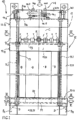
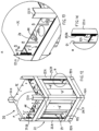
- a safety apparatus for the movement of a plurality of pneumatically interconnected gas bottles under pressure the so-called “bottle pack", according to an example of embodiment of the present invention, is indicated as a whole with 10 ( Fig. 1 ).
- Said apparatus 10 comprises:
- said sealed pneumatic circuit C and said pneumatic connector R are contained within the footprint of said plates from P1 to P4.
- said sealed pneumatic circuit C and said pneumatic connector R are arranged over a third plate P3 ( Fig. 3 ).
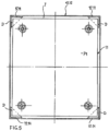
- said first plate P1 is rigidly connected, in correspondence with its four corner areas, with said vertical uprights 12.11 by means of respective metal spacer elements D, configured to determine a mutual distance between said first plate P1 and said uprights 12.11 corresponding to the width of said interspace I ( Fig. 5 ). The same distance is also maintained between the other horizontal plates, from P2 to P4, and said vertical uprights 12.11 ( Figs. 2 , 3 , 4 ).
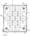
- a second plate P2 ( Fig. 4 ) is provided for retaining the bottles of said plurality of bottles B, is superimposed close to said first plate P1 and has an orderly arrangement O of through bores, having a diameter slightly larger than the external diameter of each bottle of the plurality of bottles B, which pass through said orderly arrangement O of bores of the second plate P2 and are retained in an orderly fashion.
- a third plate P3 and a further plate P4 are superimposed at a distance with respect to said second plate P2 for retaining bottles and are aligned vertically with said plates P1 and P2.
- Said two plates P3, P4 have the respective corner areas bevelled, so as to provide, in correspondence with each vertical upright 12.11, a free passage I.1.
- said third plate P3 is arranged at a level immediately under the pneumatic valve means V, the corresponding pneumatic circuit C and the respective pneumatic connector R of said plurality of bottles B ( Figs. 1 , 3 ).
- said further plate P4 is arranged close to the top of said internal support structure 11, above the pneumatic valve means V, the corresponding pneumatic circuit C and the respective pneumatic connectors V of said plurality of bottles B, and said pneumatic connector R for the flexible hose ( Figs. 1 , 2 ).
- Said screening means 13 configured like a blind comprise a box element 13.1 ( Fig. 3 ), for example made of sheet metal, without base and without cover, having four vertical side walls 13.2 and which is housed in said interspace I, between horizontal plates from P1 to P4 and vertical uprights 12.11, in a vertically mobile manner.
- a box element 13.1 for example made of sheet metal, without base and without cover, having four vertical side walls 13.2 and which is housed in said interspace I, between horizontal plates from P1 to P4 and vertical uprights 12.11, in a vertically mobile manner.
- the side walls 13.2 of the box element 13.1 are lightened by means of a large opening and each have:
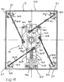
- Said transfer command means 14 comprise ( Figs 2 , 6 to 8 and 11 ) a rotating body 14.1, with the conformation of a circular disc, mounted above the further plate P4, coaxial and rotating freely with respect to a shaft 14.11 with a vertical axis, which is fixed at the centre of said further plate P4 (in the ideal point of intersection between the geometrical diagonals of said further plate P4).
- Said rotating body 14.1 carries, inferiorly, a pinion 14.2, rotating integrally therewith, coaxial with respect to said vertical shaft 14.11 and resting on a plate made of low friction material fixed to said further plate P4.
- Rack means 14.3 are kinematically engaged with said pinion 14.2 and comprise a slider 14.31, resting on said low friction plate and guided by means of a pair of rectilinear guides 14.4 fixed to the upper face of said further plate P4.
- Said slider 14.31 has the conformation of a fork, wherein a first straight branch 14.32 has an internal rack toothing, engaging with said pinion 14.2, and a second straight branch 14.33, parallel to the first branch 14.32, has a flat internal vertical face arranged in sliding contact with said pinion 14.2.
- One end of said slider 14.31 has an integral vertical flange 14.33.
- a lead screw 14.34 configured as threaded nut, is provided integral with respect to said vertical flange 14.33 of said slider 14.31 and has a threaded through bore the axis of which intersects the axis of said shaft 14.11.
- a corresponding screw 14.5 with a horizontal axis is kinematically coupled with respect to said threaded bore of said lead screw 14.34 with a threaded end part thereof, while the opposite end of said screw 14.5 has a smooth surface and is supported in a freely rotating manner by means of a corresponding bearing fixed with respect to a support 14.6, fixed to the upper face of said further plate P4, close to a perimeter edge of said plate.
- a manually operated crank 14.7 is connected with respect to said opposite end part of said screw 14.5 and is configured to selective take a first working position, in which it is in an arrangement coaxial to the screw 14.5 and on the outside of said further plate P4 and can rotate integrally with the screw 14.5 around the axis of the screw, and a second working position, rotated through 90° with respect to said first working position, in which it is within the footprint of said further plate P4 and is prevented from rotating.
- said rotating disc 14.1 supports four vertical fixed pins 14.8, extending upward and arranged symmetrically with respect to the axis of the shaft 14.11 on two vertical planes at right angles to each other passing through said axis.
- four idle transfer pulleys 14.9 are provided on the upper face of said further plate P4, each one in correspondence with a respective bevelled corner area of said further plate P4.
- the axes of two pulleys 14.9 symmetrically opposite to each other with respect to the axis of said shaft 14.11 are at right angles to a respective one of said two vertical planes of symmetry.
- Four flexible linear elements 14.10 are also provided, each configured as a metal rope.
- Each linear flexible element 14.10 is fixed, at one end, to a corresponding pin 14.8 of the rotating disc 14.1 and, at the other end, to a corresponding socket 14.12 ( Figs. 9 , 10 ) provided in a respective upper corner area of said box element 13.1 of the screening means 13.
- said box element 13.1 of the screening means 13 is suspended with respect to said four pins 14.8 integral with the rotating disc 14.1 and is vertically mobile in said interspace I.
- said box element 13.1 of the screening means 13 carries out a straight vertical upward movement between said first lowered working position ( Figs. 1 , 2 ) and said second raised working position ( Figs.
- said box element 13.1 of the screening means 13 carries out a straight vertical downward movement between said second raised working position and said first lowered working position by means of a rotation of said rotating disc 14.1 around the shaft 14.11 comprised between 60° and 90°, in clockwise direction in Figs. 2 and 11 .
- the rotation of said rotating disc 14.1 around the shaft 14.11 is controlled by an operator who manually rotates the crank 14.7, arranged in said first working position, and with it the screw 14.5, which commands transfer of the slider 14.31 and of the rack 14.32, which rotates the pinion 14.2 integral with said rotating disc 14.1.
- the lead screw 14.34 is provided with a threaded through bore, radial with respect to the axis of the screw 14.5.
- a pressure screw 14.341 is engaged in said bore and is manually taken to engage said lock screw of the screw 14.5, with a locking function, when said box element 13.1 of the screening means 13 is arranged in said second raised working position ( Figs. 11 , 10 ).
- the safety apparatus for the movement of a plurality of pneumatically interconnected gas bottles B' under pressure is indicated as a whole with 20.
- said safety apparatus 20 comprises:
- said screening means 23 configured like a blind comprise a box element, for example made of sheet metal, without base and without cover, having four vertical side walls 23.1 and which is housed in said interspace I', in a vertically mobile manner between said horizontal plates and said vertical uprights 22.11.
- the side walls 23.1 of the box element 23 are lightened by means of a respective large opening and two opposite walls 23.1 each have:
- threaded nuts 23.23 are fixed, respectively in pairs, with respect to said second integral top flanges 23.22 of two opposite walls 23.1, close to said uprights 22.11.
- Said four threaded nuts 23.23 are configured as lead screws and are engaged, by means of helical coupling, with four respective threaded rods 23.24 having a vertical axis, stably supported, capable of rotating around the respective axis, between said first plate P21 and said top cover plate PC.
- said threaded rods 23.24 can be stably supported, capable of rotating around the respective axis, with respect to said internal support structure 21 and/or with respect said external cage structure 22.
- Each vertical threaded rod 23.24 supports, in the top part and under the cover plate PC, a respective driven toothed wheel 23.25, fixed coaxially.
- the four driven toothed wheels 23.25 have the same toothing and lie in a same horizontal plane under said cover plate PC.
- a toothed belt 23.26 is configured to run between said driven toothed wheels 23.25, when driven by means of a driving toothed wheel 23.251, which is engaged with respect to said toothed belt 23.26 and is supported with respect to said internal support structure 21 and/or with respect to said external cage structure 22, in a freely rotating manner around a vertical axis.
- said driving toothed wheel 23.251 is supported with respect to said cover plate PC, in a freely rotating manner around a vertical axis.
- Said driving toothed wheel 23.251 is integral with respect to rotation means, which comprise a coaxial head (for example a hexagonal nut), configured for detachable connection with respect to a rigid drive arm AR, arranged in a plane orthogonal to the axis of said driving toothed wheel 23.251 and that, by means of manual rotation around the axis of said driving toothed wheel 23.251, integral with said same toothed wheel 23.251, allows said first lowered working position or said second raised working position of said screening means 23 to be achieved, respectively.
- said arm AR is illustrated in two distinct positions rotated around the axis of said same toothed wheel 23.251.
- the amplitude of the rotation angle of said arm AR is chosen so that, rotating said arm by this angular amplitude, said belt 23.26 is made to run correspondingly between said driven toothed wheels 23.25, determining a corresponding vertical movement of the threaded nuts 23.23 along the respective threaded rods 23.24, such as to take one of the flanges 23.21 or 23.22 of two opposite vertical walls 23.1 of the cage 23 into the respective working position, according to the direction of rotation.
- the screening means can be in the form of a simple plate configured like a blind, provided mobile with respect to said single slot for insertion of the forks of a fork lift truck.
- transfer command means can be configured differently with respect to what has been described and illustrated, and may also be provided with electric gearmotor means, in order to perform the function explained above.
- the description above refers to an example of embodiment in which the bottles of the bottle pack have respective vertical axes
- the present invention can also be implemented, as will be apparent to the person skilled in the art, in the case of a bottle pack in which the bottles are arranged with respective horizontal axes.
Landscapes
- Engineering & Computer Science (AREA)
- Mechanical Engineering (AREA)
- General Engineering & Computer Science (AREA)
- Filling Or Discharging Of Gas Storage Vessels (AREA)
- Warehouses Or Storage Devices (AREA)
Claims (11)
- Sicherheitsapparat (10, 20) zur Bewegung einer Vielzahl von pneumatisch miteinander verbundenen Druckgasflaschen (B, B'), genannt "Flaschenpaket", umfassend:- die Vielzahl von pneumatisch verbundenen Gasflaschen,- eine interne Stützstruktur (11, 21), umfassend eine Vielzahl horizontaler Platten (P1, P21; P2, P3, P4), die jeweils in verschiedenen Höhen in Bezug auf den Boden vertikal übereinander angeordnet und stabil miteinander verbunden sind,- wobei die besagte Stützstruktur (11, 21) die besagte Vielzahl von Flaschen (B, B') trägt, die ein unter Druck stehendes Gas enthalten und in einer Anordnung mit vertikalen Achsen oder mit horizontalen Achsen nebeneinander angeordnet sind,- wobei jede Flasche (B, B') der besagten Vielzahl von Flaschen entsprechende pneumatische Ventilmittel (V) zum Abfangen des Gasflusses umfasst,- wobei eine erste Platte (P1, P21), die sich unterhalb und in der Nähe des Bodens befindet, als Trägerplattform für die besagte Vielzahl von Flaschen (B, B') konfiguriert ist und in Bezug auf den Boden mittels Stützfüßen (P11, P211) angehoben ist,- wobei die besagten pneumatischen Ventilmittel (V) jeder Flasche (B, B') der besagten Vielzahl von Flaschen pneumatisch durch einen abgedichteten pneumatischen Kreislauf (C) des Sicherheitsapparats verbunden sind, um die pneumatischen Ventilmittel (V) aller Flaschen (B, B') miteinander und in Bezug auf einen pneumatischen Anschluss (R) des Sicherheitsapparats zu verbinden, der für die lösbare Verbindung eines flexiblen Schlauchs vorgesehen ist, der die pneumatische und mechanische Verbindung in Bezug auf eine externe Vorrichtung zur Verwendung des Gases herstellt bzw. um das Füllen mit Gas der Flaschen der besagten Vielzahl von Flaschen (B, B') auszuführen;- wobei der besagte pneumatische Anschluss (R) des besagten pneumatischen Kreislaufs (C) auf einem höheren Niveau angeordnet ist als der der ersten Platte (P1, P21),- wobei mindestens die besagte erste Platte (P1, P21) mit mindestens einem Paar der besagten Stützfüße (P11, P211) und mit dem Boden mindestens einen Schlitz bildet, der eine ausreichende Höhe aufweist, um den Durchgang der Gabeln eines Gabelstaplers zur Bewegung des Apparats (10, 20) zu ermöglichen;- eine externe Käfigstruktur (12, 22), die eine Vielzahl von vertikalen Pfosten (12.11, 22.11) einschließt, die um die besagten horizontalen Platten (P1, P21; P2, P3, P4) der besagten Stützstruktur (11, 21) herum angeordnet und starr in Bezug auf die besagte Stützstruktur verbunden sind;durch die Tatsache gekennzeichnet, dass der besagte Apparat (10, 20) Folgendes umfasst:- einen vertikalen Zwischenraum (I, I'), der zwischen der besagten internen Stützstruktur (11, 21) und der besagten externen Käfigstruktur (12, 22) vorgesehen ist;- Abschirmmittel (13, 23), die in dem besagten Zwischenraum (I, I') vertikal beweglich und als Fallgatter konfiguriert sind, das:- in einer ersten abgesenkten Betriebsposition den besagten mindestens einen Schlitz zwischen der besagten ersten Platte (P1, P21), dem besagten mindestens einen Paar von Stützfüßen (P11, P211) und dem Boden verschließt, während es den besagten Anschluss (R) des besagten pneumatischen Verbindungskreislaufs (C) nach außen hin nicht abschirmt und es einem Bediener möglich ist, die lösbare Verbindung zwischen dem besagten pneumatischen Anschluss (R) und dem besagten Schlauch herzustellen, und- in einer zweiten angehobenen Betriebsposition den besagten pneumatischen Anschluss (R) des besagten pneumatischen Verbindungskreislaufs (C) nach außen hin abschirmt und verhindert, dass ein Bediener die lösbare Verbindung zwischen dem besagten pneumatischen Anschluss (R) und dem besagten Schlauch herstellt, während es den besagten mindestens einen Schlitz nicht schließt, und es möglich ist, die Verlagerung des Apparats (10, 20) mittels eines Gabelstaplers auszuführen, dessen Gabeln durch den besagten mindestens einen Schlitz eingeführt werden,- und Translationssteuerungsmittel (14, 24), die konfiguriert sind, um die Verlagerung in vertikaler Richtung der besagten beweglichen Abschirmmittel (13, 23), in der besagten ersten abgesenkten Betriebsposition bzw. in der besagten zweiten angehobenen Betriebsposition, selektiv zu steuern.
- Sicherheitsapparat (10) gemäß Anspruch 1, durch die Tatsache gekennzeichnet, dass die besagte erste Platte (P1) mit den besagten vertikalen Streben (12.11) mittels entsprechender Abstandshalter (D) starr verbunden ist, die konfiguriert sind, um einen gegenseitigen Abstand zwischen der besagten ersten Platte (P1) und den besagten Streben (12.11) zu bestimmen, der mindestens der Breite des besagten Zwischenraums (I) entspricht, wobei derselbe Abstand auch zwischen den anderen horizontalen Platten (P2, P3, P4) und den besagten vertikalen Streben (12.11) eingehalten wird.
- Sicherheitsapparat (10, 20) gemäß Anspruch 1 und/oder 2, durch die Tatsache gekennzeichnet, dass die besagten als Fallgatter konfigurierten Abschirmmittel (13, 23) mindestens eine vertikale Wand (13.2, 23.1) umfassen, die Folgendes aufweist:- einen ersten unteren vertikalen Flügel (13.21, 23.21), der in der besagten ersten abgesenkten Betriebsposition der besagten Abschirmmittel (13, 23) den besagten mindestens einen Schlitz verschließt, der mindestens zwischen der besagten ersten Platte (P1, P21), dem besagten mindestens einen Paar von Stützfüßen (P11, P211) und dem Boden vorgesehen ist, und- einen zweiten oberen vertikalen Flügel (13.22, 23.22), der in der besagten zweiten angehobenen Betriebsposition der besagten Abschirmmittel (13, 23) den besagten pneumatischen Anschluss (R) des besagten pneumatischen Verbindungskreises (C) nach außen hin abschirmt und einen Bediener daran hindert, die lösbare Verbindung zwischen dem besagten pneumatischen Anschluss (R) und dem besagten Schlauch herzustellen.
- Sicherheitsapparat (10, 20) gemäß Anspruch 1, 2 und/oder 3, durch die Tatsache gekennzeichnet, dass die horizontalen Platten der besagten Vielzahl von horizontalen Platten (P1, P2, P3, P4) viereckig sind und dass die besagten als Fallgatter konfigurierten Abschirmmittel (13, 23) einen kastenförmigen Körper (13. 1) ohne Boden und ohne Deckel umfassen, der vier vertikale Seitenwände (13.2, 23.1) aufweist und der in dem besagten Zwischenraum (I, I') zwischen der besagten Vielzahl von horizontalen Platten (P1, P2, P3, P4) und den besagten vertikalen Streben (12.11, 22.11) in einer vertikal beweglichen Lage untergebracht ist.
- Sicherheitsapparat (10) gemäß einem oder mehreren der vorhergehenden Ansprüche, wobei eine weitere horizontale Platte (P4) der besagten Vielzahl von Platten (P1, P2, P3, P4) auf einem höheren Niveau als die besagte erste Platte (P1) angeordnet ist, durch die Tatsache gekennzeichnet, dass die Translationssteuerungsmittel (14) Folgendes umfassen:- einen Drehkörper (14.1), der koaxial montiert ist und sich frei in Bezug auf eine Welle (14.11) mit vertikaler Achse dreht, die in Bezug auf die besagte weitere Platte (P4) befestigt ist,- ein Ritzel (14.2), das koaxial in Bezug auf die besagte vertikale Welle (14.11) und drehfest mit dem besagten Drehkörper (14.1) verbunden ist,- Zahnstangenmittel (14.3), die mit dem besagten Ritzel (14.2) kinematisch in Anspruch genommen werden,- Mittel zum Betätigen der Schraube (14.5) und der Schraubenmutter (14.34), die konfiguriert sind, um die besagten Zahnstangenmittel (14.3) in entgegengesetzte Richtungen zu verschieben,- Mittel zur Steuerung der Drehung (14.7), die konfiguriert sind, um die Drehung in entgegengesetzte Richtungen der besagten Schraubenmittel (14.5) zu bestimmen,- eine Vielzahl von Verbindungsstellen (14.8), die in Bezug auf den besagten Drehkörper (14.1) befestigt sind,- eine Vielzahl flexibler Organe (14.10), die jeweils an einem Ende in Bezug auf eine entsprechende Verbindungsstelle der besagten Vielzahl von Verbindungsstellen (14.8) und am anderen Ende in Bezug auf eine entsprechende Verbindungsstelle (14.12) der besagten Abschirmmittel (13) befestigt sind,so dass die besagten Abschirmmittel (13) an der besagten Vielzahl von Verbindungsstellen (14.8) aufgehängt sind, befestigt an dem besagten Drehkörper (14.1), vertikal beweglich in dem besagten Zwischenraum (I) und angetrieben werden, um eine geradlinige vertikale Aufwärtsbewegung zwischen der besagten ersten abgesenkten Betriebsposition und der besagten zweiten angehobenen Betriebsposition mittels einer Drehung des besagten Drehkörpers (14. 1) um die Welle (14.11) in einer ersten Drehrichtung auszuführen, während die besagten Abschirmmittel (13) dazu geführt werden, eine geradlinige vertikale Abwärtsbewegung zwischen der besagten zweiten angehobenen Betriebsposition und der besagten ersten abgesenkten Betriebsposition mittels einer Drehung des besagten Drehkörpers (14.1) um die Welle (14.11) in einer zweiten Drehrichtung entgegengesetzt zu der besagten ersten Drehrichtung auszuführen.
- Sicherheitsapparat (10) gemäß Anspruch 5, durch die Tatsache gekennzeichnet, dass die besagte Drehung des besagten Drehkörpers (14.1) um die besagte Welle (14.11) zwischen ±30° und ±90° liegt.
- Sicherheitsapparat (10) gemäß Anspruch 5 und/oder 6, durch die Tatsache gekennzeichnet, dass die besagten Zahnstangenmittel (14.3) als Schlitten (14.31) konfiguriert sind, der in Bezug auf die besagte weitere Platte (P4) gleitet und wie eine Gabel geformt ist, wobei:- ein erster geradliniger Zweig (14.32) eine zahnstangenartige Innenverzahnung aufweist, die mit dem besagten Ritzel (14.2) in Kontakt steht, und ein zweiter geradliniger Zweig (14.33), der parallel zum ersten Zweig (14.32) verläuft, eine flache vertikale Innenseite aufweist, die in Gleitkontakt in Bezug auf den besagten Ritzel (14.2) steht,- ein Ende des Schlittens (14.31) einen integrierten vertikalen Flügel (14.33) aufweist,- eine Schraubenmutter (14.34) in Bezug auf den besagten vertikalen Flügel (14.33) des besagten Schlittens (14.31) integriert vorgesehen ist und ein durchgehendes Gewindeloch aufweist, dessen Achse die Achse der besagten Welle (14.11) durchkreuzt,- eine entsprechende Schraube (14.5) mit horizontaler Achse in Bezug auf das besagte Gewindeloch der besagten Schraubenmutter (14.34) mit einem ihrer mit Gewinde versehenen Endteil kinematisch gekoppelt ist, während der gegenüberliegende Endteil der besagten Schraube (14.5) mittels eines entsprechenden Festlagers in Bezug auf eine Halterung (14.6), die auf der oberen Fläche der besagten weiteren Platte (P4) befestigt ist, frei drehbar gestützt ist,- eine Kurbel (14.7), betriebsfähig in koaxialer Anordnung, in Bezug auf den besagten gegenüberliegenden Endteil der besagten Schraube (14.5) verbunden ist.
- Sicherheitsapparat (10) gemäß einem oder mehreren der Ansprüche 5 bis 7, wobei zumindest die besagte weitere Platte (P4) der besagten Vielzahl von Platten (P1, P2, P3, P4) viereckig ist, durch die Tatsache gekennzeichnet, dass:- die Achse der besagten Welle (14.11) des besagten Drehkörpers (14.1) in einem zentralen Bereich der besagten weiteren Platte (P4) angeordnet ist;- der besagte Drehkörper (14.1) vier feste Stifte (14.8) trägt, die als Verbindungsstellen konfiguriert sind und symmetrisch in Bezug auf die Achse der Welle (14.11) auf zwei vertikalen, zueinander orthogonalen Ebenen, die durch die besagte Achse verlaufen, angeordnet sind,- vier freie Umlenkrollen (14.9) auf einer Seite der besagten weiteren Platte (P4), jeweils in Übereinstimmung mit einem entsprechenden Eckbereich der besagten weiteren Platte (P4), vorgesehen sind,- die Achsen von zwei Umlenkrollen (14.9), die sich in Bezug auf die Achse der besagten Welle (14.11) symmetrisch gegenüberliegen, orthogonal zu einer der besagten zwei vertikalen Symmetrieebenen sind,- jedes biegsame Teil der besagten Vielzahl der biegsamen Teile (14.10) zwischen einer entsprechenden der besagten vertikalen Stifte (14.8) und einer entsprechenden Verbindungsstelle (14.12) der besagten Abschirmmittel (13) befestigt ist und mittels einer entsprechenden Umlenkrolle (14.10) zurückgeführt wird.
- Sicherheitsapparat (20) gemäß einem oder mehreren der Ansprüche 1 und von 3 bis 4, durch die Tatsache gekennzeichnet, dass die besagten Translationssteuerungsmittel (24) Mittel umfassen, die als Schraubenmuttern (23.23) konfiguriert sind, die in Bezug auf die besagten Abschirmmittel (23) befestigt sind und mittels einer schraubenförmigen Kopplung mit entsprechenden Gewindestangen (23.24) mit vertikaler Achse in Anspruch genommen werden, die mit der Möglichkeit der Drehung um ihre jeweilige Achse in Bezug auf die besagte interne Stützstruktur (21) und/oder in Bezug auf die besagte externe Käfigstruktur (22) stationär gestützt sind.
- Sicherheitsapparat (20) gemäß Anspruch 9, durch die Tatsache gekennzeichnet, dass jede vertikale Gewindestange (23.24) ein entsprechendes angetriebenes feststehendes koaxiales Zahnrad (23.25) trägt, und dass ein Zahnriemen (23.26) konfiguriert ist, um zwischen den besagten angetriebenen Zahnrädern (23. 25) umzulaufen, wenn er mittels eines Antriebszahnrads (23.251) angetrieben wird, das in Bezug auf den besagten Zahnriemen (23.26) in Anspruch genommen wird und in Bezug auf die besagte interne Stützstruktur (21) und/oder in Bezug auf die externe Käfigstruktur (22) frei drehbar um eine vertikale Achse gestützt ist.
- Sicherheitsapparat (20) gemäß Anspruch 10, durch die Tatsache gekennzeichnet, dass das besagte Antriebszahnrad (23.251) in Bezug auf mindestens einen starren Betätigungsarm (AR) verbunden ist, der in einer orthogonal zur Achse des Antriebszahnrads (23.251) liegenden Ebene angeordnet ist und der es durch manuelle Drehung um die Achse des besagten Antriebszahnrads (23.251) ermöglicht, auf eine mit dem Zahnrad (23.251) selbst fest verbundenen Weise die besagte erste abgesenkte Betriebsposition bzw. die besagte zweite angehobene Betriebsposition der besagten Abschirmmittel (23) zu erreichen.
Applications Claiming Priority (2)
| Application Number | Priority Date | Filing Date | Title |
|---|---|---|---|
| IT102020000007096A IT202000007096A1 (it) | 2020-04-03 | 2020-04-03 | Apparato di sicurezza per la movimentazione di una pluralità di bom-bole di gas in pressione tra loro pneumaticamente collegate, cosid-detto “pacco bombole” |
| PCT/IB2021/052854 WO2021199014A1 (en) | 2020-04-03 | 2021-04-06 | Safety apparatus for the movement of a plurality of pneumatically interconnected gas bottles under pressure |
Publications (3)
| Publication Number | Publication Date |
|---|---|
| EP4127556A1 EP4127556A1 (de) | 2023-02-08 |
| EP4127556B1 true EP4127556B1 (de) | 2024-04-03 |
| EP4127556C0 EP4127556C0 (de) | 2024-04-03 |
Family
ID=71170734
Family Applications (1)
| Application Number | Title | Priority Date | Filing Date |
|---|---|---|---|
| EP21723904.5A Active EP4127556B1 (de) | 2020-04-03 | 2021-04-06 | Sicherheitsvorrichtung zum bewegen mehrerer pneumatisch verbundener druckgasflaschen |
Country Status (4)
| Country | Link |
|---|---|
| US (1) | US12146616B2 (de) |
| EP (1) | EP4127556B1 (de) |
| IT (1) | IT202000007096A1 (de) |
| WO (1) | WO2021199014A1 (de) |
Families Citing this family (3)
| Publication number | Priority date | Publication date | Assignee | Title |
|---|---|---|---|---|
| CN116255560A (zh) * | 2022-12-02 | 2023-06-13 | 安徽送变电工程有限公司 | 多功能sf6充气装备及sf6充气方法 |
| US12359776B2 (en) * | 2023-03-27 | 2025-07-15 | Saudi Arabian Oil Company | Pressurized cylinder stand |
| CN117307965B (zh) * | 2023-11-29 | 2024-04-09 | 广州德标智能化工程有限公司 | 移动式防爆供气柜 |
Family Cites Families (22)
| Publication number | Priority date | Publication date | Assignee | Title |
|---|---|---|---|---|
| US3602368A (en) * | 1969-09-19 | 1971-08-31 | Sun Oil Co | Pallet for gas cylinders and the like |
| US4564109A (en) * | 1982-09-09 | 1986-01-14 | Aga, A.B. | Method and apparatus for transporting pressurized gas cylinders |
| US4481972A (en) * | 1982-09-09 | 1984-11-13 | Aga Ab | Pallet for pressurized gas cylinders |
| US5078415A (en) * | 1990-07-11 | 1992-01-07 | Norbert Goral | Mobile carrier for gas cylinders |
| US5176265A (en) * | 1992-05-08 | 1993-01-05 | Bennett Richard C | Retaining structure for pressurized gas cylinders |
| FR2762299B1 (fr) * | 1997-04-18 | 1999-06-04 | Guy Andre Gallet | Casier pour le stockage, le transport et la distribution de bouteilles de gaz |
| WO2000014782A1 (en) * | 1998-09-03 | 2000-03-16 | Nippon Sanso Corporation | Feed device for large amount of semiconductor process gas |
| US7017741B1 (en) * | 2002-09-24 | 2006-03-28 | Williamson John P | Method and apparatus for transporting pressurized gas canisters |
| US8016300B2 (en) * | 2007-10-01 | 2011-09-13 | Cramer Decker Industries | Mobile cart having a retractable-wheel base system |
| FR2985802B1 (fr) * | 2012-01-17 | 2014-03-14 | Air Liquide | Element modulaire de distribution de gaz sous pression et installation correspondante |
| FR2988158B1 (fr) * | 2012-03-15 | 2014-04-11 | Air Liquide | Cadre pour bouteilles de fluide sous pression |
| EP2682667A3 (de) * | 2012-07-04 | 2018-03-21 | L'air Liquide, Societe Anonyme Pour L'etude Et L'exploitation Des Procedes Georges Claude | Druckgaszylinderpalette |
| ES2719124T3 (es) * | 2012-12-20 | 2019-07-08 | Hoffmann La Roche | Sistema de gestión de líquidos y/o sólidos a granel |
| FR3010768B1 (fr) * | 2013-09-19 | 2017-01-13 | Air Liquide | Dispositif de fourniture de gaz |
| FR3010765B1 (fr) * | 2013-09-19 | 2015-10-16 | Air Liquide | Dispositif de fourniture de gaz |
| FR3020442B1 (fr) * | 2014-04-24 | 2017-02-17 | Air Liquide | Dispositif de fourniture de gaz |
| US9616798B2 (en) * | 2015-01-28 | 2017-04-11 | Fuelie Systems, Inc. | Portable fuel storage device |
| DE102015004738B4 (de) * | 2015-04-11 | 2019-10-24 | BBA Müller GmbH | Gasflaschenbündel zum Füllen und Entnehmen von verdichteten Gasen, insbesondere für das autogene Schweißen und Schneidbrennen |
| FR3040757B1 (fr) * | 2015-09-04 | 2018-05-11 | L'air Liquide, Societe Anonyme Pour L'etude Et L’Exploitation Des Procedes Georges Claude | Cassette de stockage pour bouteilles a fluide sous pression et un cadre de stockage associe |
| FR3054019B1 (fr) * | 2016-07-13 | 2018-11-16 | L'air Liquide, Societe Anonyme Pour L'etude Et L'exploitation Des Procedes Georges Claude | Dispositif de fourniture de gaz |
| USD827764S1 (en) * | 2016-08-31 | 2018-09-04 | Air Liquide Oil & Gas Services Limited | Gas cylinder container |
| GB2561808A (en) * | 2017-01-13 | 2018-10-31 | Linde Ag | Pressure vessel transportation apparatus and method of transporting a pressure vessel |
-
2020
- 2020-04-03 IT IT102020000007096A patent/IT202000007096A1/it unknown
-
2021
- 2021-04-06 US US17/916,571 patent/US12146616B2/en active Active
- 2021-04-06 EP EP21723904.5A patent/EP4127556B1/de active Active
- 2021-04-06 WO PCT/IB2021/052854 patent/WO2021199014A1/en not_active Ceased
Also Published As
| Publication number | Publication date |
|---|---|
| EP4127556C0 (de) | 2024-04-03 |
| US20230151931A1 (en) | 2023-05-18 |
| IT202000007096A1 (it) | 2021-10-03 |
| US12146616B2 (en) | 2024-11-19 |
| WO2021199014A1 (en) | 2021-10-07 |
| EP4127556A1 (de) | 2023-02-08 |
Similar Documents
| Publication | Publication Date | Title |
|---|---|---|
| US12146616B2 (en) | Safety apparatus for the movement of a plurality of pneumatically interconnected gas bottles under pressure | |
| EP2801402A1 (de) | Kipp-Roll-Tisch zur Verwendung beim Reinigen von UF6-Zylindern | |
| US8092070B2 (en) | Gravimetric blender with power hopper cover | |
| ES2255602T3 (es) | Dispositivo de llenado de cajas con objetos alineados. | |
| US8181568B1 (en) | Bulk bag conditioning system | |
| EP1050497A1 (de) | Vorrichtung zum Entleeren von Transport- und Lagerbehältern für Flüssigkeiten | |
| EP3142783B1 (de) | Bewegungssystem für behälter zwischen stationen für eine fluidproduktionsanlage | |
| US10201915B2 (en) | Gravimetric blender with power hopper cover | |
| CN119240206B (zh) | 在易燃易爆场景下向原料罐加注药剂的系统及方法 | |
| CN215853965U (zh) | 一种保温板搬运用机械手 | |
| CN209988648U (zh) | 一种在线式自动翻桶机构 | |
| CA1267589A (en) | Valve removal and cleaning system for container filling apparatus | |
| CN220682711U (zh) | 一种调剂设备 | |
| US20100271900A1 (en) | Mixer comprising mixing tools which are driven by the rotation of the bowl | |
| CN208516879U (zh) | 一种新型自动夹紧的电动搬运车 | |
| CN213895047U (zh) | 一种挤压用玻璃润滑垫升降装置 | |
| EP0200025B1 (de) | Vorrichtung zum Aufnehmen und Umsetzen von Gebinden | |
| CN116924312B (zh) | 一种用于将油漆自动装桶的设备 | |
| CN223149475U (zh) | 输送装置及其旋转设备 | |
| CN217996746U (zh) | 放盖装置及放盖机 | |
| CN216302482U (zh) | 一种带有限位结构的自动化输送装置 | |
| CN222960666U (zh) | 一种自动配料系统的升降式输送机构 | |
| CN214934142U (zh) | 过滤装置以及涂覆溶液过滤系统 | |
| CN220431594U (zh) | 辅助加料装置 | |
| KR102869190B1 (ko) | 중간벌크컨테이너용 이송리프트 |
Legal Events
| Date | Code | Title | Description |
|---|---|---|---|
| STAA | Information on the status of an ep patent application or granted ep patent |
Free format text: STATUS: UNKNOWN |
|
| STAA | Information on the status of an ep patent application or granted ep patent |
Free format text: STATUS: THE INTERNATIONAL PUBLICATION HAS BEEN MADE |
|
| PUAI | Public reference made under article 153(3) epc to a published international application that has entered the european phase |
Free format text: ORIGINAL CODE: 0009012 |
|
| STAA | Information on the status of an ep patent application or granted ep patent |
Free format text: STATUS: REQUEST FOR EXAMINATION WAS MADE |
|
| 17P | Request for examination filed |
Effective date: 20221027 |
|
| AK | Designated contracting states |
Kind code of ref document: A1 Designated state(s): AL AT BE BG CH CY CZ DE DK EE ES FI FR GB GR HR HU IE IS IT LI LT LU LV MC MK MT NL NO PL PT RO RS SE SI SK SM TR |
|
| DAV | Request for validation of the european patent (deleted) | ||
| DAX | Request for extension of the european patent (deleted) | ||
| GRAP | Despatch of communication of intention to grant a patent |
Free format text: ORIGINAL CODE: EPIDOSNIGR1 |
|
| STAA | Information on the status of an ep patent application or granted ep patent |
Free format text: STATUS: GRANT OF PATENT IS INTENDED |
|
| INTG | Intention to grant announced |
Effective date: 20231020 |
|
| GRAS | Grant fee paid |
Free format text: ORIGINAL CODE: EPIDOSNIGR3 |
|
| GRAA | (expected) grant |
Free format text: ORIGINAL CODE: 0009210 |
|
| STAA | Information on the status of an ep patent application or granted ep patent |
Free format text: STATUS: THE PATENT HAS BEEN GRANTED |
|
| AK | Designated contracting states |
Kind code of ref document: B1 Designated state(s): AL AT BE BG CH CY CZ DE DK EE ES FI FR GB GR HR HU IE IS IT LI LT LU LV MC MK MT NL NO PL PT RO RS SE SI SK SM TR |
|
| REG | Reference to a national code |
Ref country code: CH Ref legal event code: EP |
|
| REG | Reference to a national code |
Ref country code: DE Ref legal event code: R096 Ref document number: 602021011346 Country of ref document: DE |
|
| REG | Reference to a national code |
Ref country code: IE Ref legal event code: FG4D |
|
| U01 | Request for unitary effect filed |
Effective date: 20240502 |
|
| U07 | Unitary effect registered |
Designated state(s): AT BE BG DE DK EE FI FR IT LT LU LV MT NL PT SE SI Effective date: 20240620 |
|
| PG25 | Lapsed in a contracting state [announced via postgrant information from national office to epo] |
Ref country code: IS Free format text: LAPSE BECAUSE OF FAILURE TO SUBMIT A TRANSLATION OF THE DESCRIPTION OR TO PAY THE FEE WITHIN THE PRESCRIBED TIME-LIMIT Effective date: 20240803 |
|
| PG25 | Lapsed in a contracting state [announced via postgrant information from national office to epo] |
Ref country code: HR Free format text: LAPSE BECAUSE OF FAILURE TO SUBMIT A TRANSLATION OF THE DESCRIPTION OR TO PAY THE FEE WITHIN THE PRESCRIBED TIME-LIMIT Effective date: 20240403 |
|
| PG25 | Lapsed in a contracting state [announced via postgrant information from national office to epo] |
Ref country code: GR Free format text: LAPSE BECAUSE OF FAILURE TO SUBMIT A TRANSLATION OF THE DESCRIPTION OR TO PAY THE FEE WITHIN THE PRESCRIBED TIME-LIMIT Effective date: 20240704 |
|
| PG25 | Lapsed in a contracting state [announced via postgrant information from national office to epo] |
Ref country code: ES Free format text: LAPSE BECAUSE OF FAILURE TO SUBMIT A TRANSLATION OF THE DESCRIPTION OR TO PAY THE FEE WITHIN THE PRESCRIBED TIME-LIMIT Effective date: 20240403 |
|
| PG25 | Lapsed in a contracting state [announced via postgrant information from national office to epo] |
Ref country code: CZ Free format text: LAPSE BECAUSE OF FAILURE TO SUBMIT A TRANSLATION OF THE DESCRIPTION OR TO PAY THE FEE WITHIN THE PRESCRIBED TIME-LIMIT Effective date: 20240403 |
|
| PG25 | Lapsed in a contracting state [announced via postgrant information from national office to epo] |
Ref country code: PL Free format text: LAPSE BECAUSE OF FAILURE TO SUBMIT A TRANSLATION OF THE DESCRIPTION OR TO PAY THE FEE WITHIN THE PRESCRIBED TIME-LIMIT Effective date: 20240403 |
|
| PG25 | Lapsed in a contracting state [announced via postgrant information from national office to epo] |
Ref country code: PL Free format text: LAPSE BECAUSE OF FAILURE TO SUBMIT A TRANSLATION OF THE DESCRIPTION OR TO PAY THE FEE WITHIN THE PRESCRIBED TIME-LIMIT Effective date: 20240403 Ref country code: NO Free format text: LAPSE BECAUSE OF FAILURE TO SUBMIT A TRANSLATION OF THE DESCRIPTION OR TO PAY THE FEE WITHIN THE PRESCRIBED TIME-LIMIT Effective date: 20240703 Ref country code: IS Free format text: LAPSE BECAUSE OF FAILURE TO SUBMIT A TRANSLATION OF THE DESCRIPTION OR TO PAY THE FEE WITHIN THE PRESCRIBED TIME-LIMIT Effective date: 20240803 Ref country code: HR Free format text: LAPSE BECAUSE OF FAILURE TO SUBMIT A TRANSLATION OF THE DESCRIPTION OR TO PAY THE FEE WITHIN THE PRESCRIBED TIME-LIMIT Effective date: 20240403 Ref country code: GR Free format text: LAPSE BECAUSE OF FAILURE TO SUBMIT A TRANSLATION OF THE DESCRIPTION OR TO PAY THE FEE WITHIN THE PRESCRIBED TIME-LIMIT Effective date: 20240704 Ref country code: ES Free format text: LAPSE BECAUSE OF FAILURE TO SUBMIT A TRANSLATION OF THE DESCRIPTION OR TO PAY THE FEE WITHIN THE PRESCRIBED TIME-LIMIT Effective date: 20240403 Ref country code: CZ Free format text: LAPSE BECAUSE OF FAILURE TO SUBMIT A TRANSLATION OF THE DESCRIPTION OR TO PAY THE FEE WITHIN THE PRESCRIBED TIME-LIMIT Effective date: 20240403 Ref country code: RS Free format text: LAPSE BECAUSE OF FAILURE TO SUBMIT A TRANSLATION OF THE DESCRIPTION OR TO PAY THE FEE WITHIN THE PRESCRIBED TIME-LIMIT Effective date: 20240703 |
|
| U42 | Public notification for the european patent with unitary effect |
Free format text: INSPECTION PLACE: MUNICH; ADDRESSEE: PARISI, FULVIO,IT; COMMUNICATION PURSUANT TO RULE 10(1) UPR (EPO FORM 7030A DATED 26.08.2024) |
|
| REG | Reference to a national code |
Ref country code: CH Ref legal event code: PL |
|
| REG | Reference to a national code |
Ref country code: DE Ref legal event code: R097 Ref document number: 602021011346 Country of ref document: DE |
|
| PG25 | Lapsed in a contracting state [announced via postgrant information from national office to epo] |
Ref country code: RO Free format text: LAPSE BECAUSE OF FAILURE TO SUBMIT A TRANSLATION OF THE DESCRIPTION OR TO PAY THE FEE WITHIN THE PRESCRIBED TIME-LIMIT Effective date: 20240403 Ref country code: SK Free format text: LAPSE BECAUSE OF FAILURE TO SUBMIT A TRANSLATION OF THE DESCRIPTION OR TO PAY THE FEE WITHIN THE PRESCRIBED TIME-LIMIT Effective date: 20240403 |
|
| PG25 | Lapsed in a contracting state [announced via postgrant information from national office to epo] |
Ref country code: SM Free format text: LAPSE BECAUSE OF FAILURE TO SUBMIT A TRANSLATION OF THE DESCRIPTION OR TO PAY THE FEE WITHIN THE PRESCRIBED TIME-LIMIT Effective date: 20240403 |
|
| PG25 | Lapsed in a contracting state [announced via postgrant information from national office to epo] |
Ref country code: SM Free format text: LAPSE BECAUSE OF FAILURE TO SUBMIT A TRANSLATION OF THE DESCRIPTION OR TO PAY THE FEE WITHIN THE PRESCRIBED TIME-LIMIT Effective date: 20240403 Ref country code: SK Free format text: LAPSE BECAUSE OF FAILURE TO SUBMIT A TRANSLATION OF THE DESCRIPTION OR TO PAY THE FEE WITHIN THE PRESCRIBED TIME-LIMIT Effective date: 20240403 Ref country code: RO Free format text: LAPSE BECAUSE OF FAILURE TO SUBMIT A TRANSLATION OF THE DESCRIPTION OR TO PAY THE FEE WITHIN THE PRESCRIBED TIME-LIMIT Effective date: 20240403 Ref country code: CH Free format text: LAPSE BECAUSE OF NON-PAYMENT OF DUE FEES Effective date: 20240430 Ref country code: MC Free format text: LAPSE BECAUSE OF FAILURE TO SUBMIT A TRANSLATION OF THE DESCRIPTION OR TO PAY THE FEE WITHIN THE PRESCRIBED TIME-LIMIT Effective date: 20240403 |
|
| PLBE | No opposition filed within time limit |
Free format text: ORIGINAL CODE: 0009261 |
|
| STAA | Information on the status of an ep patent application or granted ep patent |
Free format text: STATUS: NO OPPOSITION FILED WITHIN TIME LIMIT |
|
| 26N | No opposition filed |
Effective date: 20250106 |
|
| U42 | Public notification for the european patent with unitary effect |
Free format text: INSPECTION PLACE: MUNICH; ADDRESSEE: PARISI, FULVIO,IT; COMMUNICATION PURSUANT TO RULE 10(1) UPR (EPO FORM 7030A DATED 26.08.2024) |
|
| PG25 | Lapsed in a contracting state [announced via postgrant information from national office to epo] |
Ref country code: IE Free format text: LAPSE BECAUSE OF NON-PAYMENT OF DUE FEES Effective date: 20240406 |
|
| U20 | Renewal fee for the european patent with unitary effect paid |
Year of fee payment: 5 Effective date: 20250421 |
|
| PGFP | Annual fee paid to national office [announced via postgrant information from national office to epo] |
Ref country code: GB Payment date: 20250531 Year of fee payment: 5 |
|
| PG25 | Lapsed in a contracting state [announced via postgrant information from national office to epo] |
Ref country code: CY Free format text: LAPSE BECAUSE OF FAILURE TO SUBMIT A TRANSLATION OF THE DESCRIPTION OR TO PAY THE FEE WITHIN THE PRESCRIBED TIME-LIMIT; INVALID AB INITIO Effective date: 20210406 |
|
| PG25 | Lapsed in a contracting state [announced via postgrant information from national office to epo] |
Ref country code: HU Free format text: LAPSE BECAUSE OF FAILURE TO SUBMIT A TRANSLATION OF THE DESCRIPTION OR TO PAY THE FEE WITHIN THE PRESCRIBED TIME-LIMIT; INVALID AB INITIO Effective date: 20210406 |
|
| U42 | Public notification for the european patent with unitary effect |
Free format text: INSPECTION PLACE: MUNICH; ADDRESSEE: PARISI, FULVIO,IT; COMMUNICATION PURSUANT TO RULE 10(1) UPR (EPO FORM 7030A DATED 26.08.2024) |
|
| PG25 | Lapsed in a contracting state [announced via postgrant information from national office to epo] |
Ref country code: TR Free format text: LAPSE BECAUSE OF FAILURE TO SUBMIT A TRANSLATION OF THE DESCRIPTION OR TO PAY THE FEE WITHIN THE PRESCRIBED TIME-LIMIT Effective date: 20240403 |
|
| U20 | Renewal fee for the european patent with unitary effect paid |
Year of fee payment: 6 Effective date: 20260416 |