EP4127490B1 - Bremsventil mit dichteinrichtung und verfahren hierzu - Google Patents
Bremsventil mit dichteinrichtung und verfahren hierzu Download PDFInfo
- Publication number
- EP4127490B1 EP4127490B1 EP21716311.2A EP21716311A EP4127490B1 EP 4127490 B1 EP4127490 B1 EP 4127490B1 EP 21716311 A EP21716311 A EP 21716311A EP 4127490 B1 EP4127490 B1 EP 4127490B1
- Authority
- EP
- European Patent Office
- Prior art keywords
- brake valve
- compressed air
- air passage
- sealing
- sealing device
- Prior art date
- Legal status (The legal status is an assumption and is not a legal conclusion. Google has not performed a legal analysis and makes no representation as to the accuracy of the status listed.)
- Active
Links
Images

Classifications
-
- F—MECHANICAL ENGINEERING; LIGHTING; HEATING; WEAPONS; BLASTING
- F15—FLUID-PRESSURE ACTUATORS; HYDRAULICS OR PNEUMATICS IN GENERAL
- F15B—SYSTEMS ACTING BY MEANS OF FLUIDS IN GENERAL; FLUID-PRESSURE ACTUATORS, e.g. SERVOMOTORS; DETAILS OF FLUID-PRESSURE SYSTEMS, NOT OTHERWISE PROVIDED FOR
- F15B21/00—Common features of fluid actuator systems; Fluid-pressure actuator systems or details thereof, not covered by any other group of this subclass
- F15B21/005—Filling or draining of fluid systems
-
- F—MECHANICAL ENGINEERING; LIGHTING; HEATING; WEAPONS; BLASTING
- F15—FLUID-PRESSURE ACTUATORS; HYDRAULICS OR PNEUMATICS IN GENERAL
- F15B—SYSTEMS ACTING BY MEANS OF FLUIDS IN GENERAL; FLUID-PRESSURE ACTUATORS, e.g. SERVOMOTORS; DETAILS OF FLUID-PRESSURE SYSTEMS, NOT OTHERWISE PROVIDED FOR
- F15B21/00—Common features of fluid actuator systems; Fluid-pressure actuator systems or details thereof, not covered by any other group of this subclass
- F15B21/04—Special measures taken in connection with the properties of the fluid
- F15B21/044—Removal or measurement of undissolved gas, e.g. de-aeration, venting or bleeding
-
- B—PERFORMING OPERATIONS; TRANSPORTING
- B60—VEHICLES IN GENERAL
- B60T—VEHICLE BRAKE CONTROL SYSTEMS OR PARTS THEREOF; BRAKE CONTROL SYSTEMS OR PARTS THEREOF, IN GENERAL; ARRANGEMENT OF BRAKING ELEMENTS ON VEHICLES IN GENERAL; PORTABLE DEVICES FOR PREVENTING UNWANTED MOVEMENT OF VEHICLES; VEHICLE MODIFICATIONS TO FACILITATE COOLING OF BRAKES
- B60T17/00—Component parts, details, or accessories of power brake systems not covered by groups B60T8/00, B60T13/00 or B60T15/00, or presenting other characteristic features
- B60T17/002—Air treatment devices
- B60T17/004—Draining and drying devices
-
- F—MECHANICAL ENGINEERING; LIGHTING; HEATING; WEAPONS; BLASTING
- F16—ENGINEERING ELEMENTS AND UNITS; GENERAL MEASURES FOR PRODUCING AND MAINTAINING EFFECTIVE FUNCTIONING OF MACHINES OR INSTALLATIONS; THERMAL INSULATION IN GENERAL
- F16K—VALVES; TAPS; COCKS; ACTUATING-FLOATS; DEVICES FOR VENTING OR AERATING
- F16K24/00—Devices, e.g. valves, for venting or aerating enclosures
- F16K24/04—Devices, e.g. valves, for venting or aerating enclosures for venting only
- F16K24/042—Devices, e.g. valves, for venting or aerating enclosures for venting only actuated by a float
- F16K24/044—Devices, e.g. valves, for venting or aerating enclosures for venting only actuated by a float the float being rigidly connected to the valve element, the assembly of float and valve element following a substantially translational movement when actuated, e.g. also for actuating a pilot valve
- F16K24/046—Devices, e.g. valves, for venting or aerating enclosures for venting only actuated by a float the float being rigidly connected to the valve element, the assembly of float and valve element following a substantially translational movement when actuated, e.g. also for actuating a pilot valve the assembly of float and valve element being a single spherical element
-
- F—MECHANICAL ENGINEERING; LIGHTING; HEATING; WEAPONS; BLASTING
- F16—ENGINEERING ELEMENTS AND UNITS; GENERAL MEASURES FOR PRODUCING AND MAINTAINING EFFECTIVE FUNCTIONING OF MACHINES OR INSTALLATIONS; THERMAL INSULATION IN GENERAL
- F16K—VALVES; TAPS; COCKS; ACTUATING-FLOATS; DEVICES FOR VENTING OR AERATING
- F16K31/00—Actuating devices; Operating means; Releasing devices
- F16K31/12—Actuating devices; Operating means; Releasing devices actuated by fluid
- F16K31/18—Actuating devices; Operating means; Releasing devices actuated by fluid actuated by a float
- F16K31/20—Actuating devices; Operating means; Releasing devices actuated by fluid actuated by a float actuating a lift valve
- F16K31/22—Actuating devices; Operating means; Releasing devices actuated by fluid actuated by a float actuating a lift valve with the float rigidly connected to the valve
-
- F—MECHANICAL ENGINEERING; LIGHTING; HEATING; WEAPONS; BLASTING
- F15—FLUID-PRESSURE ACTUATORS; HYDRAULICS OR PNEUMATICS IN GENERAL
- F15B—SYSTEMS ACTING BY MEANS OF FLUIDS IN GENERAL; FLUID-PRESSURE ACTUATORS, e.g. SERVOMOTORS; DETAILS OF FLUID-PRESSURE SYSTEMS, NOT OTHERWISE PROVIDED FOR
- F15B2211/00—Circuits for servomotor systems
- F15B2211/50—Pressure control
- F15B2211/505—Pressure control characterised by the type of pressure control means
- F15B2211/50563—Pressure control characterised by the type of pressure control means the pressure control means controlling a differential pressure
-
- F—MECHANICAL ENGINEERING; LIGHTING; HEATING; WEAPONS; BLASTING
- F15—FLUID-PRESSURE ACTUATORS; HYDRAULICS OR PNEUMATICS IN GENERAL
- F15B—SYSTEMS ACTING BY MEANS OF FLUIDS IN GENERAL; FLUID-PRESSURE ACTUATORS, e.g. SERVOMOTORS; DETAILS OF FLUID-PRESSURE SYSTEMS, NOT OTHERWISE PROVIDED FOR
- F15B2211/00—Circuits for servomotor systems
- F15B2211/50—Pressure control
- F15B2211/55—Pressure control for limiting a pressure up to a maximum pressure, e.g. by using a pressure relief valve
-
- F—MECHANICAL ENGINEERING; LIGHTING; HEATING; WEAPONS; BLASTING
- F15—FLUID-PRESSURE ACTUATORS; HYDRAULICS OR PNEUMATICS IN GENERAL
- F15B—SYSTEMS ACTING BY MEANS OF FLUIDS IN GENERAL; FLUID-PRESSURE ACTUATORS, e.g. SERVOMOTORS; DETAILS OF FLUID-PRESSURE SYSTEMS, NOT OTHERWISE PROVIDED FOR
- F15B2211/00—Circuits for servomotor systems
- F15B2211/80—Other types of control related to particular problems or conditions
- F15B2211/885—Control specific to the type of fluid, e.g. specific to magnetorheological fluid
- F15B2211/8855—Compressible fluids, e.g. specific to pneumatics
Definitions
- the invention relates to a brake valve for a pneumatic brake system for vehicles according to claim 1.
- the invention relates, inter alia, to the brake valve with at least one venting path for venting the brake valve, wherein the venting path of the brake valve comprises a sealing device which is designed to change at least between a normal state and a sealed state, and to a method for assembling the brake valve, which comprises arranging a sealing device in a first compressed air passage of the brake valve.
- the invention further relates to a method for preventing fluid from entering a pressure-carrying section of a brake valve according to claim 20 and a method for assembling a brake valve according to claim 23, as well as the use of a ball for producing a sealing state of a brake valve according to claim 24.
- pneumatic devices of the type described above are often used in environments where various foreign media may be present.
- pneumatic braking systems and their components such as relay valves, may be exposed to water from their environment, for example during cleaning, when operating in or after rain, during floods or when deliberately wading through bodies of water.
- Pneumatic devices of the type described above typically have pneumatic connections to an environment of the pneumatic device, for example in order to vent excess pressure from a pressure-carrying section of the pneumatic device, or to carry out a pressure equalization with the environment of the pneumatic device.
- the pneumatic connection to the environment of the pneumatic device can allow foreign media in the environment to penetrate the pneumatic device.
- the penetration of liquids such as water can impair the functionality of the pneumatic device.
- the penetration of foreign media, particularly water can lead to corrosion or, for example, to a complete failure of the braking system due to the freezing of water. Measures must therefore be taken to make the unwanted penetration of foreign media more difficult or, ideally, prevent it.
- Pneumatic devices with sealing devices are known from the state of the art, which are intended to make it more difficult for small amounts of splash water or water below a certain level to enter unintentionally.
- GB 2 401 330 A , DE 10 2016 011 032 A1 and DE 28 29 290 A1 such pneumatic devices.
- WO00/15958A1 discloses a valve assembly comprising a valve housing defining an open interior; an inlet opening; a valve seat with an outlet opening extending therethrough; and a float support region.
- EP2345816A2 relates to a venting device for a hydraulic cylinder, in particular of a dual-clutch transmission, with a flow channel having an inlet and an outlet, passing through the venting device, and a closing element which releases the outlet at least in a first functional position and closes it in a second functional position.
- DE2910086A1 discloses a device for filling and relieving a hydraulic system that can accommodate a limited amount of fluid.
- the object is achieved by a brake valve for a pneumatic brake system for vehicles with at least one venting path for venting the brake valve along an outflow direction, wherein the venting path comprises a first volume through which flow can pass, a first compressed air passage and a sealing device.
- the first compressed air passage pneumatically connects the first volume to a pressure-carrying section of the brake valve.
- the sealing device is designed to switch at least between a normal state and a sealed state.
- the brake valve When the brake valve is vented, compressed air is passed from the pressure-carrying part of the brake valve through the first compressed air passage into the first volume through which it can flow.
- the compressed air can be passed from the first volume through which it can flow to an environment of the brake valve.
- the brake valve comprises a second compressed air passage that pneumatically connects the first volume to the environment.
- the venting process is driven by an overpressure that prevails in the pressure-carrying part of the brake valve compared to the first volume and/or the environment.
- the outflow direction is defined along the flow path described by the outflowing compressed air through the venting path, starting from the pressure-carrying part through the first compressed air passage to the first volume and optionally to the environment of the brake valve.
- the inflow direction is opposite to the outflow direction and extends along the venting path, starting from the first volume through the first compressed air passage to the pressure-bearing part of the brake valve.
- the inflow direction extends from the environment through the first volume, the first compressed air passage and to the pressure-bearing part of the brake valve.
- the first compressed air passage can only flow in the outflow direction, but not in the inflow direction, whereby the sealing device fulfils the function of a check valve in the sealed state and forms a check valve in this state. This can prevent unwanted penetration of foreign media into the pressure-bearing part of the brake valve along the inflow direction.
- the sealing device is in the normal state.
- the first compressed air passage can flow freely. For example, as described above, advantageous pressure equalization along the inflow direction can be possible.
- the sealing device is designed to, when a foreign medium, in particular a liquid, in the first volume, Threshold value is exceeded to change from the normal state to the sealed state.
- the threshold value can be determined such that the presence of foreign medium at or below the threshold value defines the normal operation of the brake valve, and the presence of foreign medium above the threshold value defines the special operating state.
- the threshold value can be a height of a column of liquid in the first volume. It can thus be possible to ensure that the sealing device reliably changes to the sealed state in the special operating state.
- the foreign medium is water.
- water should also be understood below to mean aqueous liquids and mixed fluids that contain predominantly or to a large extent water, such as mud, moor or swamp water.
- the sealing device is preferably arranged in the first compressed air passage. It is further preferred that the sealing device comprises a sealing body and a sealing seat, wherein the sealing body is designed to bear sealingly against the sealing seat in the sealed state.
- the sealing body is designed to float on water.
- a sealing body according to the present invention can also float on gaseous foreign media.
- the sealing body has an average density of 900 kg/m 3 or less, of 800 kg/m 3 or less, of 700 kg/m 3 or less, particularly preferably of 600 kg/m 3 or less.
- the average density of the sealing body can be adapted in a suitable manner if the penetration of foreign media other than water is to be prevented. If the sealing body is buoyant on water or another foreign medium, i.e. its average density is lower than that of water or the other foreign medium, then exceeding the threshold value by the foreign medium can advantageously lead to the resulting buoyancy force pressing the sealing body against the seal seat.
- the sealing seat or a section thereof has a normal downstream in the outflow direction, which has at least one component that is parallel and aligned in the same direction to the outflow direction in the region of the sealing device.
- the scalar product between this normal and the outflow direction in the region of the sealing device is greater than zero.
- the sealing body is arranged downstream of the sealing seat in the outflow direction.
- the sealing body is movable between a first position and a second position, with the sealing body assuming the first position in the normal state and the second position in the sealed state.
- the sealing body lies sealingly against the sealing seat and thus forms a check valve together with the sealing seat.
- the sealing body does not lie against the sealing seat, so that flow through an area between the sealing body and the sealing seat is possible.
- the first position is downstream of the second position in the outflow direction.
- the sealing device further comprises a guide for the sealing body, so that the sealing body is movable along the guide between the first and second positions.
- the guide defines a direction of movement for the sealing body between the first and second positions, which is preferably parallel to the outflow direction at least in sections.
- the sealing seat is provided at an end of the guide located upstream in the outflow direction.
- the sealing seat is formed integrally thereon.
- the guide has a stop at an end downstream in the outflow direction, which is designed to prevent the sealing body from escaping from the guide.
- the sealing seat, sealing body and guide can thus form a structural unit that can be installed as a separate sealing device in existing brake valves. or can be retrofitted.
- the sealing body is a ball and the guide is a ball cage.
- the ball preferably has a closed cavity. This reduces the average density of the ball compared to the density of the material from which a shell of the ball is made, in particular so that the ball has an average density that is lower than the density of the foreign medium.
- the sealing body is optionally a cylinder, a disk, a cone, a truncated cone or an ellipsoid, whereby such an alternative sealing body preferably also has a closed cavity.
- the ball cage has a plurality of guide rails extending in the outflow direction. It is also preferred that the first compressed air passage is designed in the shape of a channel, i.e. that a cross section of the first compressed air passage has dimensions that are smaller than the length of the compressed air passage defined along the outflow direction.
- the brake valve is designed so that the first compressed air passage is arranged vertically at least in sections in an installation situation of the brake valve. For example, this can support the sealing body floating on the foreign medium and a resulting movement of the sealing body from the first to the second position. It is also preferred that the pressure-carrying section of the brake valve is arranged above the first volume in an installation situation of the brake valve.
- An installation situation of the brake valve can in particular include installation in a vehicle.
- the brake valve is a relay valve.
- the object mentioned at the outset is achieved by a method for preventing fluid ingress along an inflow direction into a pressure-carrying part of a brake valve according to claim 20.
- the liquid causes the sealing device to be sealed by exceeding the threshold value.
- the liquid is preferably water.
- the method further comprises venting the pressure-carrying portion of the brake valve along the outflow direction.
- this is achieved by a method for assembling a brake valve according to claim 23.
- a method for assembling a brake valve according to claim 23 can be advantageous if an existing brake valve is to be retrofitted with a sealing device with a sealing device described in relation to the first aspect of the invention.
- the object mentioned at the outset is achieved by using a ball to produce a sealing state of the brake valve according to claim 24.
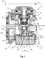
- Figure 1 shows a cross section through a brake valve of an embodiment according to the first aspect of the invention, wherein a sealing body is arranged in a second position.
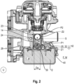
- Figure 2 shows the cross section Figure 1 , wherein a first position of the sealing body is shown in dashed lines.
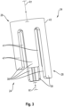
- Figure 3 shows a guide for a sealing body, as used in the embodiment of the Figures 1 and 2 and other embodiments of the invention.
- Figure 4 shows a cross section of the sealing body according to the Figure 3 .
- the Figures 1 and 2 show a pneumatic device 1 in the form of a brake valve according to the invention with a venting path 10 in an installation situation.
- the venting path 10 is designed to vent a pressure-carrying part 16 of the pneumatic device 1.
- a first volume 12 of the pneumatic device 1 is pneumatically connected to a pressure-carrying part 16 of the pneumatic device 1 via a first compressed air passage 14.
- a second compressed air passage 40 pneumatically connects an environment U of the pneumatic device 1 to the first volume 12.
- compressed air flows from the pressure-carrying part 16 through the first passage 14, through the first volume 12 and then through the second compressed air passage 40 into the environment U.
- the flow path thus described The compressed air predominantly follows a, schematically indicated by a double-bent arrow in the Figures 1 and 2 indicated outflow direction R1.
- a liquid F with a level H1 is present in the environment U, so that the entire pneumatic device 1 is arranged below the level H1 and surrounded by liquid F.
- the pneumatic device 1 has a threshold value S for the liquid F, which in the illustrated embodiment is arranged in the area of the second compressed air passage 40. Since the second compressed air passage 40 is arranged below the level H1, liquid F could penetrate into the first volume 12 through the second compressed air passage 40. As the Figure 1 , the level H1 of the liquid F is above the threshold value S. The liquid F therefore completely fills the first volume 12 and the first compressed air passage 14 at least to the extent that the liquid F exceeds the threshold value S therein.
- Figure 2 shows the pneumatic device 1 from Figure 1 , whereby in this illustration a liquid F is present in the environment U of the pneumatic device 1 with a second level H2.
- Figure 2 not provided with all reference symbols that are in Figure 1 are registered, but it should be understood that the Figures 1 and 2 show the same pneumatic device 1.
- the level H2 is below the threshold value S, but above the second compressed air passage 40.
- the liquid F therefore fills the first volume 12 almost completely up to the level H2, the first compressed air passage 14 is predominantly free of liquid F.
- the threshold value S is therefore not reached by the liquid F in the pneumatic device 1.
- the pneumatic device 1 comprises a sealing device 18 which is arranged in the first compressed air passage 14.
- the first compressed air passage 14 shown is a channel-shaped cylindrical connecting section between the first volume 12 and the pressure-bearing part 16.
- Channel-shaped in this context means that the length L of the first compressed air passage 14 is greater than the diameter D of its cross-section.
- the outflow direction R1 and the inflow direction R2 explained below are determined in the area of the first compressed air passage 14 by its geometry and run along the length L.
- the sealing device 18 shown extends over the entire length L of the first compressed air passage 14.
- sealing device 18 in the Figures 1 and 2 a sealing body 20, a guide 24 for the sealing body 20 and a sealing seat 23 provided at an end 28 of the guide 24 located downstream in the outflow direction R1.
- the sealing body 20 is designed to rest sealingly against the sealing seat 23 in a sealing state Z2.
- the sealing body 20 is a hollow ball 32 and the guide 24 is a ball cage 34 adapted to the ball 32.
- the ball 32 is movable along the ball cage 34 between a first position P1 (in Fig. 2 shown) and a second position P2 (in Fig. 1 shown).
- the sealing seat 23 is formed by a surface 22 running around the ball cage 34 in its interior.
- the surrounding surface 22 corresponds predominantly to the surface of a truncated cone, at the end of which the edge 21 is located downstream in the outflow direction R1.
- the sealing seat 23 points downstream in the outflow direction R1, ie a normal N on the surrounding surface 22 has at least one component Nv which is parallel and aligned with the outflow direction R1 (see Fig. 4 ).
- the liquid F could, without appropriate countermeasures, flow along the inflow direction R2 from the environment U through the first volume 12, through the first compressed air passage 14, up to the pressure-bearing part 16.
- the inflow direction R2 is shown schematically as an arrow running predominantly parallel to the outflow direction R1 in Figure 1 shown.
- the sealing device 18 is designed to switch at least between a normal state Z1 and a sealing state Z2.
- the sealing device 18 is shown in the sealing state Z2, in which the ball 32 is in the second position P2.
- the position P2 is located at the upstream end 26 of the guide 24 in the outflow direction R1.
- the ball 32 lies sealingly against the sealing seat 23, in particular against the edge 21, so that flow through the first compressed air passage 14 in the inflow direction R2 is prevented.
- the closed cavity 33 preferably provided within the ball 32 reduces its average density compared to the density of the material from which the ball 32 is made to such an extent that it can float on the liquid F.
- a filling material with a low density can be provided in order to increase the dimensional stability of the ball 32. Since the ball 32 is arranged downstream of the seal seat 23 in the ball cage 34 in the outflow direction R1, the resulting buoyancy force F A presses the ball 32 sealingly against the edge 21 of the seal seat 23. If the pressure-bearing part 16 is vented in the sealing state Z2, a pressure force F P resulting from an excess pressure P Ü in the pressure-bearing part 16 on the ball 32, which is directed opposite to the buoyancy force F A , can exceed the latter's amount.
- the sealing device 18 fulfils the function of a check valve in the sealing state Z2 and preferably forms one in this state.
- the size of the closed cavity 33 in the ball 32 is adapted to the density of the material of the shell 35 of the ball 32 and the density of the liquid F against which the pressure-bearing part 16 is to be sealed, in order to achieve an average density that allows the ball 34 to float on the liquid F.
- the sealing body 20 is designed, by appropriately adapting its average density, so that the ball 32 lifts off the seal seat 23 at a certain excess pressure P Ü .
- the material of the ball 32 is matched to the material of the ball cage 34 and/or the seal seat 23 in order to achieve the desired sealing properties.
- the ball 32 and the ball cage 34 and/or the seal seat 23 are made either from the same or from different materials.
- Suitable materials for ball 32 and ball cage 34 and/or seal seat 23 are, for example, metals such as brass and copper and their alloys, in particular bronze. Also suitable are thermoplastic, thermosetting and elastomeric plastics, for example silicone, PTFE, PE, PA, PP and POM or materials obtained from renewable raw materials such as rubber or cellulose.
- a sealing device 18 is not limited to the embodiment shown.
- the first compressed air passage 14 and/or the sealing device 18 is designed differently than in the Figures 1 and 2 shown, not exclusively arranged vertically.
- the sealing seat 23 is at least partially aligned vertically downwards, ie that a normal on a surface of the sealing seat 23 has at least one component that is aligned vertically downwards.
- the sealing device 18, instead of being completely in the first compressed air passage 14, is only partially in the first compressed air passage 14 and/or on, below or next to the first compressed air passage 14.
- the shape of the sealing body 20 is not limited to the ball 32 shown.
- Other embodiments of the sealing body 20 can have other shapes, for example that of a cylinder, a disk, a cone, a truncated cone or ellipsoid.
- the shape of the guide 24 is not limited to a linear guide that surrounds the sealing body 20, as represented by the ball cage 34.
- the guide 24 is designed to be spiral-shaped and/or designed so that the sealing body 20 is guided along or next to the guide 24.
- the guide 24 is not positively locking, as by the ball cage 34, but by a force, for example by magnetic attraction, which preloads the sealing body 20 in the direction of the seal seat 23. It is also preferred to combine a preload with a positively locking guide 24.
- the sealing body 20 is not limited to having a closed cavity 33 therein in order to be able to float on the liquid F.
- the sealing body 20 can thus be made entirely or partially from a material that has a lower density than the liquid F.
- a material can be foam, in particular closed-pore foam.
- a closed cavity 33 of a sealing body 20 can be filled with a material that has a lower density than the material of the casing 35 of the sealing body 20. In particular, it is possible to fill the cavity 33 with foam or with gas.
- the level H2 of the liquid F is below the threshold value S.
- the sealing device 18 is in the normal state Z1, in which the ball 32 is not arranged in the second position P2, but for example in the first position P1 as shown.
- This first position P1 of the ball 32 is in Figure 2 marked by a dashed line and arranged at the end 28 of the guide 24 located downstream in the outflow direction R1.
- the ball 32 does not rest on the seal seat 23, the ball 32 and the seal seat 23 are spaced apart from one another.
- the first compressed air passage 14 can flow through both in the outflow direction R1 and in the inflow direction R2.
- the ball 32 Since the ball 32 is linearly movable along the guide 24 along the degree of freedom M and is able to float on the liquid F, the ball 32 can assume any intermediate position between the first position P1 and the second position P2 according to a level of the liquid F which lies between the second level H2 and the threshold value S.
- a stop 30 is provided at the downstream end 28 of the guide 24, which prevents the ball 32 from escaping from the guide 24 when the level of the liquid F falls below the level H2 shown.
- the stop 30 can be arranged as shown in the Figures 1 and 2 shown, be a pot-shaped sieve which is designed to prevent particles in the liquid F from entering the first compressed air passage 14. If such particles enter the area of the seal seat 23, they can impair the proper sealing effect of the sealing device 18.
- the embodiment shown is particularly preferred because the sealing device 18 can be moved by the liquid F itself into the second position P2, and thus from the normal state Z1 into the sealing state Z2, by the ball 32 floating on the liquid F when the level of the liquid F rises above the threshold value S. Furthermore, the embodiment shown is particularly preferred because the threshold value S can be achieved by combining the arrangement of the sealing seat 23 with the properties of the ball 32, in particular its average density and diameter D a , is specified.
- the threshold value S corresponds to the level of the liquid F in the first volume 12 and/or in the first compressed air passage 14 at which the ball 32 comes into contact with the sealing seat 23 by floating on the liquid F.
- the sealing device 18 is designed to detect the exceeding of the threshold value S by the liquid F by means of suitable devices, such as sensors, and to establish the sealing state Z2 by means of suitable devices, for example actuators.
- the threshold value S is predetermined by the position of a sensor and/or the measuring point of the sensor.
- the sealing device 18 is not limited to the shown combination of guide 24, sealing seat 23 and sealing body 20. Any sealing device that can switch between the normal state Z1 and the sealing state Z2 can replace the sealing device 18 shown. It is thus possible to use a check valve that can be held in the open position by means of suitable devices, for example by means of electronic actuators, as the sealing device 18.
- the embodiment shown is also particularly preferred because the elements of the sealing device 18, in particular the ball 32 and the ball cage 34, can be present separately from the pneumatic device 1, wherein it may be possible to retrofit an existing pneumatic device 1 with a sealing device 18 according to the present invention.
- the brake valve 1 can be designed with a relay valve R for a pneumatic brake system B, the brake system B being shown in its installation situation in a commercial vehicle.
- a brake valve 1 has a first compressed air passage between a first volume and a pressure-bearing part.
- FIGS. 3 and 4 show a ball cage 34 which serves as a guide 24 in the pneumatic device 1 of the Figures 1 and 2 and can also be used in other, not shown, embodiments of the pneumatic device 1.
- Figure 4 is a sectional view through the Figure 3 Ball cage 34 shown from the outside.
- the ball cage 34 has a plurality of guide rails 38 extending from the downstream end 26 in the outflow direction R1.
- the latter At the downstream end 26 of the ball cage 34 in the outflow direction R1, the latter has a section 43 which is continuous in the circumferential direction and in which the sealing seat 23 with the circumferential surface 22 and edge 21 is also arranged.
- the guide rails 38 are arranged around the circumference of the ball cage 34 and are spaced apart from one another in the circumferential direction, so that a predominantly cylindrical cavity 44 having a diameter of D i is arranged inside the ball cage 34. In the cavity 44, the ball 34 is guided by the guide rails 38 in its movement between the first position P1 and the second position P2.
- a flow channel 41 is arranged between two spaced-apart guide rails 38.
- the embodiment shown is particularly preferred because it allows an outer diameter D a of the ball 32 (see Fig. 2 ) and the diameter D i of the cavity 44 are designed in such a way that the ball 32 is guided in the cage 34 with no or only slight play and with only slight friction.
- the flow channels 41 in the ball cage 34 enable the pneumatic device 1 to be vented, with the outflowing compressed air flowing around the ball 32 by means of the flow channels 41.
- the ball cage 24 is designed monolithically, ie guide rails 38, continuous section 43 and seal seat 23 consist of a continuous piece.
- the monolithic ball cage 24 is made of a single material.
- individual sections of the ball cage 24 are manufactured separately and connected to the ball cage 24.
- the guide rails 38 from a first material that facilitates sliding or rolling of the ball 32 along the guide rails 38, such as PTFE or bronze.
- the sealing seat 23 consists of a second material that is beneficial to the sealing effect between the sealing seat 23 and the ball 32.
- the sealing seat 23 can be coated with a material that improves the sealing effect.
- the outer diameter D A of the ball cage 34 is adapted to the cross-sectional diameter D of the first compressed air passage 14 (see Fig. 1 ) so that the ball cage 34 can be mounted in the first compressed air passage 14, preferably by means of a press fit.
- the ball cage 34 has extended guide rails 39, which extend further in the outflow direction R1 than the other, shorter, guide rails 47.
- the inner diameter Ds of the stop 30 is larger than the inner diameter D i of the ball cage 34, and is not arranged coaxially with the first compressed air passage 14, i.e. eccentrically thereto.
- the ends of the shorter guide rails 47 located downstream in the outflow direction R1 are flush with a side wall 48 of the cup-shaped stop 30.
- the extended guide rails 39 extend into an inner region of the cup-shaped stop 30, and are aligned in such a way that they separate an area 50 of the stop 30 that is not in direct alignment with the inner cavity 44 of the ball cage 34.
- the ball cage 34 is thus designed in such a way that it prevents the ball 32 from escaping into the area 50 of the stop 30. This prevents the ball 32 from jamming when the liquid level rises between the stop 30 and the cage 34, and thus possibly being prevented from moving from the first position P1 to the second position P2.
- the liquid F against which the pressure-bearing section 16 is to be directed is water W.
- the average density of the sealing body 20 is preferably 1000 kg/m 3 or less, 900 kg/m 3 or less, 800 kg/m 3 or less, 700 kg/m 3 or less or 600 kg/m 3 or less.
- the sealing body 20 preferably has a density selected from an interval defined from a maximum value to 0 kg/m 3 , the maximum value being included in the interval. The maximum value is particularly preferably any value from 1000 kg/m 3 to 0.01 kg/m 3 .
Landscapes
- Engineering & Computer Science (AREA)
- General Engineering & Computer Science (AREA)
- Mechanical Engineering (AREA)
- Chemical & Material Sciences (AREA)
- Analytical Chemistry (AREA)
- Physics & Mathematics (AREA)
- Fluid Mechanics (AREA)
- Transportation (AREA)
- Sealing Devices (AREA)
- Check Valves (AREA)
- Valves And Accessory Devices For Braking Systems (AREA)
Description
- Die Erfindung betrifft ein Bremsventil für eine pneumatische Bremsanlage für Fahrzeuge gemäß Anspruch 1. Die Erfindung bezieht sich auf u.a. das Bremsventil mit mindestens einem Entlüftungspfad zum Entlüften des Bremsventils, wobei der Entlüftungspfad des Bremsventils eine Dichteinrichtung umfasst, die dazu ausgelegt ist, mindestens zwischen einem Normalzustand und einem Dichtzustand zu wechseln, sowie ein Verfahren zur Montage des Bremsventils, welches das Anordnen einer Dichteinrichtung in einer ersten Druckluftpassage des Bremsventils umfasst.
- Die Erfindung betrifft ferner ein Verfahren zum Verhindern von Flüssigkeitseintritt in einen druckführenden Abschnitt eines Bremsventils gemäß Anspruch 20 und ein Verfahren zur Montage eines Bremsventils gemäß Anspruch 23, sowie die Verwendung einer Kugel zur Herstellung eines Dichtzustands eines Bremsventils gemäß Anspruch 24.
- Häufig werden Pneumatikvorrichtungen der vorstehend beschriebenen Art in Umgebungen eingesetzt, in denen verschiedene Fremdmedien anwesend sein können. Insbesondere pneumatische Bremsanlagen und ihre Komponenten, wie Relaisventile, können Wasser aus ihrer Umgebung ausgesetzt sein, beispielsweise bei der Reinigung, beim Betrieb im oder nach Regen, bei Überschwemmungen oder beim gezielten Durchwaten von Gewässern.
- Pneumatikvorrichtungen der eingangs beschriebenen Art weisen typischerweise pneumatische Verbindungen zu einer Umgebung der Pneumatikvorrichtung auf, beispielsweise um einen Überdruck aus einem druckführenden Abschnitt der Pneumatikvorrichtung zu entlüften, oder um einen Druckausgleich mit der Umgebung der Pneumatikvorrichtung durchzuführen. Eine solche pneumatische Verbindung zur Umgebung der Pneumatikvorrichtung kann jedoch Fremdmedien, die sich in der Umgebung befinden, das Eindringen in die Pneumatikvorrichtung erlauben. Insbesondere das Eindringen von Flüssigkeiten, wie beispielsweise Wasser, kann die Funktionalität der Pneumatikvorrichtung beeinträchtigen. So kann im Fall von pneumatischen Bremsanlagen ein Eindringen von Fremdmedien, insbesondere von Wasser, zu Korrosion oder beispielsweise durch das Gefrieren von Wasser zu einem kompletten Ausfall der Bremsanlage führen. Daher sind Maßnahmen zu treffen, um das ungewollte Eindringen von Fremdmedien zu erschweren oder bestenfalls zu verhindern.
- Aus dem Stand der Technik sind Pneumatikvorrichtungen mit Dichteinrichtungen bekannt, die ein ungewolltes Eindringen von geringen Mengen an Spritzwasser bzw. Wasser unterhalb eines gewissen Pegels erschweren sollen. Unter anderem offenbaren
GB 2 401 330 A DE 10 2016 011 032 A1 undDE 28 29 290 A1 solche Pneumatikvorrichtungen. -
WO00/15958A1 -
EP2345816A2 betrifft eine Entlüftungseinrichtung für einen Hydraulikzylinder, insbesondere eines Doppelkupplungsgetriebes, mit einem einen Einlass und einen Auslass aufweisenden, die Entlüftungseinrichtung durchsetzenden Strömungskanal, und einem den Auslass wenigstens in einer ersten Funktionsstellung freigebendes und in einer zweiten Funktionsstellung verschließendes Verschließelement. -
DE2910086A1 offenbart ein Gerät zum Füllen und Entlasten einer eine begrenzte Flüssigkeitsmenge aufnehmbaren Hydraulikanlage. - Aufgabe der vorliegenden Erfindung ist es, den sicheren Betrieb eines Bremsventils für eine pneumatische Bremsanlage für Fahrzeuge der eingangs beschriebenen Art auch in Umgebungen zu ermöglichen, in denen große Mengen eines Fremdmediums, insbesondere Wasser, anwesend sind.
- In einem ersten Aspekt wird die Aufgabe durch ein Bremsventil für eine pneumatische Bremsanlage für Fahrzeuge mit mindestens einem Entlüftungspfad zum Entlüften des Bremsventils entlang einer Ausströmrichtung gelöst, wobei der Entlüftungspfad ein durchströmbares erstes Volumen, eine erste Druckluftpassage und eine Dichteinrichtung umfasst. Die erste Druckluftpassage verbindet das erste Volumen pneumatisch mit einem druckführenden Abschnitt des Bremsventils. Die Dichteinrichtung ist dazu ausgelegt, mindestens zwischen einem Normalzustand und einem Dichtzustand zu wechseln.
- Wenn ein Entlüften des Bremsventils erfolgt, wird Druckluft vom druckführenden Teil des Bremsventils durch die erste Druckluftpassage in das durchströmbare erste Volumen geleitet. Optional kann die Druckluft vom durchströmbaren ersten Volumen an eine Umgebung des Bremsventils geleitet werden. In bevorzugten Ausführungsformen umfasst das Bremsventil eine zweite Druckluftpassage, die das erste Volumen pneumatisch mit der Umgebung verbindet. Typischerweise ist der Entlüftungsvorgang von einem Überdruck, der im druckführenden Teil des Bremsventils im Vergleich zum ersten Volumen und/oder der Umgebung herrscht, getrieben. Die Ausströmrichtung ist entlang dem von der ausströmenden Druckluft beschriebenen Strömungsweg durch den Entlüftungspfad, ausgehend vom druckführenden Teil durch die erste Druckluftpassage bis hin zum ersten Volumen und optional bis hin zur Umgebung des Bremsventils, definiert.
- Die Einströmrichtung ist der Ausströmrichtung entgegengesetzt und erstreckt sich entlang des Entlüftungspfads, ausgehend vom ersten Volumen durch die erste Druckluftpassage hin zum druckführenden Teil des Bremsventils. Optional erstreckt sich die Einströmrichtung von der Umgebung ausgehend durch das erste Volumen, die erste Druckluftpassage und hin zum druckführenden Teil des Bremsventils.
- Im Normalzustand ist die erste Druckluftpassage sowohl in der Ausströmrichtung als auch in der Einströmrichtung durchströmbar. Somit kann es vorteilhaft möglich bleiben, dass ein eventuell gewünschter geringer Druckausgleich von höherem Druck im ersten Volumen und/oder der Umgebung zum druckführenden Teil des Bremsventils entlang der Einströmrichtung stattfinden kann. Jedenfalls ermöglicht der Normalzustand ein ungehindertes Entlüften entlang der Ausström richtung.
- Im Dichtzustand ist die erste Druckluftpassage nur in der Ausströmrichtung durchströmbar, nicht aber in der Einströmrichtung, wobei die Dichteinrichtung im Dichtzustand die Funktion eines Rückschlagventils erfüllt und in diesem Zustand ein Rückschlagventil bildet. Hierdurch kann ein unerwünschtes Eindringen von Fremdmedien in den druckführenden Teil des Bremsventils entlang der Einströmrichtung verhindert werden.
- Im Normalbetrieb des Bremsventils, der beispielsweise dann vorliegt, wenn die Umgebungsbedingungen ein Eindringen von Fremdmedium aus dem ersten Volumen und/oder der Umgebung in den druckführenden Teil des Bremsventils mit hinreichender Wahrscheinlichkeit ausschließen, befindet sich die Dichteinrichtung im Normalzustand. Die erste Druckluftpassage kann frei durchströmt werden. Beispielsweise kann so, wie vorstehend beschrieben, ein vorteilhafter Druckausgleich entlang der Einströmrichtung möglich sein.
- Erst in einem besonderen Betriebszustand, in dem beispielsweise mit einem Eindringen von Fremdmedium aus dem ersten Volumen und/oder der Umgebung in den druckführenden Teil gerechnet werden muss, wechselt die Dichteinrichtung in den Dichtzustand. Dieser ermöglicht wie vorstehend beschrieben weiterhin das Entlüften des Bremsventils, verhindert jedoch den unerwünschten Eintritt von Fremdmedium in den druckführenden Teil des Bremsventils.
- In einer bevorzugten Ausführungsform ist die Dichteinrichtung dazu ausgelegt, wenn ein Fremdmedium, insbesondere eine Flüssigkeit, im ersten Volumen einen Schwellenwert überschreitet, vom Normalzustand in den Dichtzustand zu wechseln. Der Schwellenwert kann so bestimmt sein, dass die Anwesenheit von Fremdmedium am oder unterhalb des Schwellenwerts den Normalbetrieb des Bremsventils definiert, und die Anwesenheit von Fremdmedium oberhalb des Schwellenwerts den besonderen Betriebszustand definiert. Beispielsweise kann der Schwellenwert eine Höhe einer im ersten Volumen befindlichen Flüssigkeitssäule sein. Somit kann es möglich sein, sicherzustellen, dass die Dichteinrichtung im besonderen Betriebszustand zuverlässig in den Dichtzustand wechselt. Insbesondere ist das Fremdmedium Wasser. Unter den Begriff Wasser sollen im Folgenden auch wässrige Flüssigkeit und Mischfluide verstanden werden, die überwiegend oder zu einem großen Teil Wasser enthalten, wie z.B. Schlamm, Moor- oder Sumpfwasser.
- Bevorzugt ist die Dichteinrichtung in der ersten Druckluftpassage angeordnet. Ferner ist es bevorzugt, dass die Dichteinrichtung einen Dichtkörper und einen Dichtungssitz umfasst, wobei der Dichtkörper dazu ausgelegt ist, im Dichtzustand dichtend an dem Dichtungssitz anzuliegen. Insbesondere ist der Dichtkörper dazu ausgelegt, auf Wasser schwimmfähig zu sein. Es soll jedoch verstanden werden, dass ein Dichtkörper gemäß der vorliegenden Erfindung auch auf gasförmigen Fremdmedien schwimmfähig sein kann. Vorzugsweise weist der Dichtkörper eine mittlere Dichte von 900 kg/m3 oder weniger, von 800 kg/m3 oder weniger, von 700 kg/m3 oder weniger, besonders bevorzugt von 600 kg/m3 oder weniger auf. Die mittlere Dichte des Dichtkörpers kann in geeigneter Weise angepasst werden, wenn das Eindringen anderer Fremdmedien als Wasser verhindert werden soll. Falls der Dichtkörper auf Wasser, oder einem anderen Fremdmedium, schwimmfähig ist, d. h. seine mittlere Dichte geringer als die von Wasser oder dem anderen Fremdmedium ist, so kann vorteilhaft ein Überschreiten des Schwellenwerts durch das Fremdmedium dazu führen, dass die resultierende Auftriebskraft den Dichtkörper gegen den Dichtungssitz presst.
- Bevorzugt weist der Dichtungssitz oder ein Abschnitt von diesem in Ausströmrichtung stromabwärts eine Normale auf, die zumindest eine Komponente hat, die parallel und gleichgerichtet zur Ausströmrichtung im Bereich der Dichteinrichtung ist. In anderen Worten ausgedrückt, das Skalarprodukt zwischen dieser Normalen und der Ausströmrichtung im Bereich der Dichteinrichtung ist größer Null. Ferner ist es bevorzugt, dass der Dichtkörper in Ausströmrichtung stromabwärts von dem Dichtungssitz angeordnet ist.
- In einer bevorzugten Ausführungsform ist der Dichtkörper zwischen einer ersten Position und einer zweiten Position beweglich, wobei der Dichtkörper im Normalzustand die erste Position, und im Dichtzustand die zweite Position einnimmt. Dabei liegt der Dichtkörper in der ersten Position dichtend am Dichtungssitz an und bildet so zusammen mit dem Dichtungssitz ein Rückschlagventil. In der zweiten Position liegt der Dichtkörper nicht an dem Dichtungssitz an, so dass ein Durchströmen eines Bereichs zwischen Dichtkörper und Dichtungssitz möglich ist. Insbesondere liegt die erste Position in Ausströmrichtung stromabwärts von der zweiten Position.
- Bevorzugt weist die Dichteinrichtung ferner eine Führung für den Dichtkörper auf, sodass der Dichtkörper entlang der Führung zwischen der ersten und zweiten Position beweglich ist. Insbesondere definiert die Führung zwischen der ersten und zweiten Position eine Bewegungsrichtung für den Dichtkörper, die bevorzugt zumindest abschnittsweise parallel zur Ausströmrichtung ist. Ferner ist es bevorzugt, dass der Dichtungssitz an einem in Ausströmrichtung stromaufwärts gelegenen Ende der Führung vorgesehen ist. Vorzugsweise ist der Dichtungssitz einstückig daran ausgebildet.
- Ebenso ist es bevorzugt, dass die Führung an einem in Ausströmrichtung stromabwärts gelegenen Ende einen Anschlag aufweist, der dazu ausgelegt ist, ein Austreten des Dichtkörpers aus der Führung zu verhindern. Vorzugsweise können somit Dichtungssitz, Dichtkörper und Führung eine strukturelle Einheit bilden, die als separate Dichteinrichtung in bestehende Bremsventile eingebaut bzw. nachgerüstet werden kann. Insbesondere ist der Dichtkörper eine Kugel und die Führung ein Kugelkäfig. Vorzugsweise weist die Kugel einen geschlossenen Hohlraum auf. Dadurch wird die mittlere Dichte der Kugel, im Vergleich zur Dichte des Materials aus dem ein Mantel der Kugel gefertigt ist, gesenkt, insbesondere sodass die Kugel eine mittlere Dichte aufweist, die geringer ist als die Dichte des Fremdmediums. In alternativen Ausführungsformen ist der Dichtkörper wahlweise ein Zylinder, eine Scheibe, ein Kegel, ein Kegelstumpf oder ein Ellipsoid, wobei ein solcher alternativer Dichtkörper vorzugsweise ebenfalls einen geschlossenen Hohlraum aufweist.
- In einer bevorzugten Ausführungsform weist der Kugelkäfig eine Mehrzahl an, sich in Ausströmrichtung erstreckenden, Führungsschienen auf. Ferner ist es bevorzugt, dass die erste Druckluftpassage kanalförmig ausgestaltet ist, das heißt, dass ein Querschnitt der ersten Druckluftpassage Dimensionen aufweist, die kleiner sind als die entlang der Ausströmrichtung definierte Länge der Druckluftpassage.
- Es ist bevorzugt, dass das Bremsventil dazu ausgelegt ist, dass die erste Druckluftpassage in einer Einbausituation des Bremsventils zumindest abschnittsweise vertikal angeordnet ist. Beispielsweise kann so ein Aufschwimmen des Dichtkörpers auf dem Fremdmedium und eine sich daraus ergebende Bewegung des Dichtkörpers von der ersten in die zweite Position unterstützt werden. Ebenso ist es bevorzugt, dass der druckführende Abschnitt des Bremsventils in einer Einbausituation des Bremsventils oberhalb des ersten Volumens angeordnet ist. Eine Einbausituation des Bremsventils kann insbesondere den Einbau in einem Fahrzeug umfassen.
- In besonders bevorzugten Ausführungsformen ist das Bremsventil ein Relaisventil.
- In einem zweiten Aspekt der Erfindung wird die eingangs genannte Aufgabe durch ein Verfahren zum Verhindern von Flüssigkeitseintritt entlang einer Einströmrichtung in einen druckführenden Teil eines Bremsventils gemäß Anspruch 20 gelöst.
- In einer bevorzugten Ausführungsform des Verfahrens verbringt die Flüssigkeit dadurch, dass sie den Schwellenwert überschreitet, die Dichteinrichtung in den Dichtzustand. Insbesondere wird dies, wie in Bezug auf den ersten Aspekt der Erfindung beschrieben, dadurch ermöglicht, dass eine Auftriebskraft auf die Dichteinrichtung wirkt. Bevorzugt ist die Flüssigkeit Wasser.
- Es ist bevorzugt, dass das Verfahren ferner das Entlüften des druckführenden Abschnitts des Bresmventils entlang der Ausströmrichtung umfasst.
- In einem dritten Aspekt der Erfindung durch ein Verfahren zur Montage eines Bremsventils gemäß Anspruch 23 gelöst. Insbesondere kann ein solches Montageverfahren vorteilhaft sein, wenn ein vorhandenes Bremsventil mit einer Dichteinrichtung mit einer in Bezug auf den ersten Aspekt der Erfindung beschriebenen Dichteinrichtung, nachgerüstet werden soll.
- In einem vierten Aspekt der Erfindung wird die eingangs genannte Aufgabe durch die Verwendug einer Kugel zur Herstellung eines Dichtzustands des Bremsventils gemäß Anspruch 24 gelöst.
- Weitere Merkmale, Vorteile und Unteraspekte der vorstehend beschriebenen Aspekte der Erfindung ergeben sich aus der nachfolgenden Beschreibung der Figuren, die bevorzugte Ausführungsformen der Erfindung zeigen.
-
Figur 1 zeigt einen Querschnitt durch ein Bremsventil eines Ausführungsbeispiels nach dem ersten Aspekt der Erfindung, wobei ein Dichtkörper in einer zweiten Position angeordnet ist. -
Figur 2 zeigt den Querschnitt ausFigur 1 , wobei eine erste Position des Dichtkörpers gestrichelt dargestellt ist. -
Figur 3 zeigt eine Führung für einen Dichtkörper, wie sie in dem Ausführungsbeispiel derFiguren 1 und2 sowie weiteren erfindungsgemäßen Ausführungsbeispielen verwendet werden kann. -
Figur 4 zeigt einen Querschnitt des Dichtkörpers gemäß derFigur 3 . - Im Nachfolgenden werden der erste, zweite, dritte und vierte Aspekt der vorliegenden Erfindung in Bezug auf ein, insbesondere in
Figuren 1 und2 dargestelltes, Ausführungsbeispiel eines erfindungsgemäßen Bremsventils nach dem ersten Aspekt der Erfindung erläutert. Wie aus der folgenden Beschreibung zu entnehmen ist, ist das gezeigte Bremsventil dazu eingerichtet, aber nicht darauf beschränkt, ein Verfahren nach dem zweiten und/oder vierten Aspekt der Erfindung durchzuführen und/oder mittels eines Verfahrens nach dem dritten Aspekt der Erfindung montiert zu werden. Es soll verstanden werden, dass die in Zusammenhang mit denFiguren 1-4 beschriebenen Merkmale und Vorteile auf alle eingangs beschriebenen Aspekte und Unteraspekte der Erfindung übertragbar sind. - Die
Figuren 1 und2 zeigen eine Pneumatikvorrichtung 1 in der Form eines erfindungsgemäßen Bremsventils mit einem Entlüftungspfad 10 in einer Einbausituation. Der Entlüftungspfad 10 ist dazu eingerichtet, einen druckführenden Teil 16 der Pneumatikvorrichtung 1 zu entlüften. Hierzu ist ein erstes Volumen 12 der Pneumatikvorrichtung 1 über eine erste Druckluftpassage 14 mit einem druckführenden Teil 16 der Pneumatikvorrichtung 1 pneumatisch verbunden. Eine zweite Druckluftpassage 40 verbindet eine Umgebung U der Pneumatikvorrichtung 1 pneumatisch mit dem ersten Volumen 12. Beim Entlüften des druckführenden Teils 16 strömt Druckluft vom druckführenden Teil 16 durch die erste Passage 14, durch das erste Volumen 12 und dann durch die zweite Druckluftpassage 40 in die Umgebung U. Der so beschriebene Strömungspfad der Druckluft folgt überwiegend einer, schematisch mittels eines zweifach abknickenden Pfeils in denFiguren 1 und2 angedeuteten, Ausströmrichtung R1. - In
Figur 1 ist in der Umgebung U eine Flüssigkeit F mit Pegelstand H1 vorhanden, sodass die gesamte Pneumatikvorrichtung 1 unterhalb des Pegelstands H1 angeordnet und von Flüssigkeit F umgeben ist. Die Pneumatikvorrichtung 1 weist einen Schwellenwert S für die Flüssigkeit F auf, der im dargestellten Ausführungsbeispiel im Bereich der zweiten Druckluftpassage 40 angeordnet ist. Da die zweite Druckluftpassage 40 unterhalb des Pegelstands H1 angeordnet ist, konnte durch die zweite Druckluftpassage 40 Flüssigkeit F in das erste Volumen 12 eindringen. Wie derFigur 1 zu entnehmen ist, befindet sich der Pegelstand H1 der Flüssigkeit F oberhalb des Schwellenwerts S. Die Flüssigkeit F füllt deshalb das erste Volumen 12 vollständig und die erste Druckluftpassage 14 zumindest soweit, dass die Flüssigkeit F den Schwellenwert S darin überschreitet. -
Figur 2 zeigt die Pneumatikvorrichtung 1 ausFigur 1 , wobei in dieser Darstellung eine Flüssigkeit F in der Umgebung U der Pneumatikvorrichtung 1 mit einem zweiten Pegelstand H2 vorhanden ist. Aus Gründen der besseren Lesbarkeit istFigur 2 nicht mit allen Bezugszeichen versehen, die inFigur 1 eingetragen sind, es soll jedoch verstanden werden, dass dieFiguren 1 und2 dieselbe Pneumatikvorrichtung 1 zeigen. Der Pegelstand H2 befindet sich unterhalb des Schwellenwerts S, jedoch oberhalb der zweiten Druckluftpassage 40. Die Flüssigkeit F füllt deshalb das erste Volumen 12 annähernd vollständig bis zum Pegelstand H2, die erste Druckluftpassage 14 ist überwiegend frei von Flüssigkeit F. Der Schwellenwert S wird von der Flüssigkeit F in der Pneumatikvorrichtung 1 also nicht erreicht. - Im Ausführungsbeispiel der
Figuren 1 und2 umfasst die Pneumatikvorrichtung 1 eine Dichteinrichtung 18, die in der ersten Druckluftpassage 14 angeordnet ist. Insbesondere ist die gezeigte erste Druckluftpassage 14 ein kanalförmiger zylindrischer Verbindungsabschnitt zwischen dem ersten Volumen 12 und dem druckführenden Teil 16. Kanalförmig bedeutet in diesem Zusammenhang, dass die Länge L der ersten Druckluftpassage 14 größer als der Durchmesser D ihres Querschnitts ist. Die Ausströmrichtung R1, und die nachfolgend erläuterte Einströmrichtung R2, werden im Bereich der ersten Druckluftpassage 14 durch deren Geometrie vorgegeben, und verlaufen darin entlang der Länge L. Die dargestellte Dichteinrichtung 18 erstreckt sich über die gesamte Länge L der ersten Druckluftpassage 14. - Ferner umfasst die Dichteinrichtung 18 in den
Figuren 1 und2 einen Dichtkörper 20, eine Führung 24 für den Dichtkörper 20 und einen an einem, in Ausströmrichtung R1 stromabwärts gelegenen, Ende 28 der Führung 24 vorgesehenen Dichtungssitz 23. Der Dichtkörper 20 ist dazu ausgelegt, in einem Dichtzustand Z2 dichtend am Dichtungssitz 23 anzuliegen. - Der Dichtkörper 20 ist im gezeigten Ausführungsbeispiel eine hohle Kugel 32 und die Führung 24 ein an die Kugel 32 angepasster Kugelkäfig 34. Die Kugel 32 ist entlang des Kugelkäfigs 34 zwischen einer ersten Position P1 (in
Fig. 2 dargestellt) und einer zweiten Position P2 (inFig. 1 dargestellt) beweglich. Der Dichtungssitz 23 wird durch eine in dessen Inneren um den Kugelkäfig 34 umlaufende Fläche 22 gebildet. Die umlaufende Fläche 22 entspricht überwiegend der Mantelfläche eines Kegelstumpfs, an deren in Ausströmrichtung R1 stromabwärts gelegenen Ende die Kante 21 angeordnet ist. Der Dichtungssitz 23 weist in Ausströmrichtung R1 stromabwärts, d. h. eine Normale N auf der umlaufenden Fläche 22 hat zumindest eine Komponente Nv die parallel und gleichgerichtet mit der Ausströmrichtung R1 ist (sieheFig. 4 ). - Wie eingangs beschrieben ist es für den sicheren Betrieb der Pneumatikvorrichtung 1 vorteilhaft, dass ein Eintritt der Flüssigkeit F in den druckführenden Teil 16 der Pneumatikvorrichtung 1 zuverlässig verhindert wird. Insbesondere bei einem ersten Pegelstand H1 wie in der
Figur 1 könnte die Flüssigkeit F, ohne entsprechende Gegenmaßnahmen, entlang der Einströmrichtung R2 von der Umgebung U durch das erste Volumen 12, durch die erste Druckluftpassage 14, bis in den druckführenden Teil 16 ansteigen. Die Einströmrichtung R2 ist als überwiegend parallel zur Ausströmrichtung R1 verlaufender Pfeil schematisch inFigur 1 dargestellt. - Um einen solchen Wassereintritt in den druckführenden Teil 16 zu verhindern, ist die Dichteinrichtung 18 dazu ausgelegt, mindestens zwischen einem Normalzustand Z1 und einem Dichtzustand Z2 zu wechseln. In
Figur 1 ist die Dichteinrichtung 18 im Dichtzustand Z2 gezeigt, in dem die Kugel 32 in der zweiten Position P2 befindlich ist. Die Position P2 liegt am in Ausströmrichtung R1 stromaufwärts gelegenen Ende 26 der Führung 24. In dieser zweiten Position P2 liegt die Kugel 32 dichtend am Dichtungssitz 23 an, im Speziellen an der Kante 21, sodass ein Durchströmen der ersten Druckluftpassage 14 in der Einströmrichtung R2 verhindert wird. Der vorzugsweise innerhalb der Kugel 32 vorgesehene geschlossene Hohlraum 33 senkt deren mittlere Dichte im Vergleich zur Dichte des Materials aus dem die Kugel 32 gefertigt ist soweit ab, dass diese auf der Flüssigkeit F schwimmfähig ist. Alternativ kann ein Füllmaterial mit einer geringen Dichte vorgesehen sein, um die Formstabilität der Kugel 32 zu erhöhen. Da die Kugel 32 in Ausströmrichtung R1 stromabwärts des Dichtungssitzes 23 im Kugelkäfig 34 angeordnet ist, presst die resultierende Auftriebskraft FA die Kugel 32 dichtend gegen die Kante 21 des Dichtungssitzes 23. Wenn im Dichtzustand Z2 ein Entlüften des druckführenden Teils 16 durchgeführt wird, so kann eine aus einem Überdruck PÜ im druckführenden Teil 16 auf die Kugel 32 resultierende Druckkraft FP, die der Auftriebskraft FA entgegen gerichtet ist, deren Betrag übersteigen. Die Kugel 32 wird somit durch die Druckkraft FP für die Dauer des Entlüftungsvorganges vom Dichtungssitz 23 abgehoben, sodass Druckluft aus dem druckführenden Teil16 entlang der Ausströmrichtung R1 entlüftet werden kann. Durch die ausströmende Luft wird dann ein Eindringen von Flüssigkeit verhindert. Im Dichtzustand Z2 ist die erste Druckluftpassage 14 also nur in der Ausströmrichtung R1 durchströmbar. Anders ausgedrückt erfüllt die Dichteinrichtung 18 im Dichtzustand Z2 die Funktion eines Rückschlagventils und bildet in diesem Zustand vorzugsweise eines. - Es ist bevorzugt, dass die Größe des geschlossenen Hohlraumes 33 in der Kugel 32 entsprechend der Dichte des Materials des Mantels 35 der Kugel 32 und der Dichte der Flüssigkeit F, gegen die der druckführende Teil 16 gedichtet werden soll, angepasst ist, um eine mittlere Dichte zu erreichen, die ein Schwimmen der Kugel 34 auf der Flüssigkeit F ermöglicht. Ferner ist es bevorzugt, dass der Dichtkörper 20 durch entsprechende Anpassung seiner mittleren Dichte dazu ausgelegt ist, dass die Kugel 32 bei einem bestimmten Überdruck PÜ vom Dichtungssitz 23 abhebt. Es ist bevorzugt, dass das Material der Kugel 32 auf das Material des Kugelkäfigs 34 und/oder des Dichtungssitzes 23 abgestimmt ist, um die gewünschten Dichteigenschaften zu erreichen. Wahlweise sind Kugel 32 und Kugelkäfig 34 und/oder Dichtungssitz 23 entweder aus dem gleichen oder aus unterschiedlichen Materialien gefertigt. Geeignete Materialien für Kugel 32 und Kugelkäfig 34 und/oder Dichtungssitz 23 sind beispielsweise Metalle wie Messing und Kupfer sowie deren Legierungen, insbesondere Bronze. Ebenso geeignet sind thermoplastische, duroplastische und elastomere Kunststoffe, beispielsweise Silikone, PTFE, PE, PA, PP und POM oder aus nachwachsenden Rohstoffen gewonnene Materialien wie Kautschuk oder Zellulose.
- Es soll verstanden werden, dass eine Dichteinrichtung 18 gemäß der vorliegenden Erfindung nicht auf die dargestellte Ausführungsform beschränkt ist. Beispielsweise ist in weiteren Ausführungsbeispielen die erste Druckluftpassage 14 und/oder die Dichteinrichtung 18 anders als in den
Figuren 1 und2 dargestellt, nicht ausschließlich vertikal angeordnet. Damit ein Aufschwimmen des Dichtkörper 20 auf der Flüssigkeit F den Dichtkörper 20 gegen den Dichtungssitz 23 presst ist es ausreichend, wenn der Dichtungssitz 23 zumindest teilweise vertikal nach unten weisend ausgerichtet ist, d. h. dass eine Normale auf einer Fläche des Dichtungssitzes 23 zumindest eine Komponente aufweist die vertikal nach unten ausgerichtet ist. Ferner ist es möglich, dass die Dichteinrichtung 18, statt vollständig in der ersten Druckluftpassage 14 nur teilweise in der ersten Druckluftpassage 14 und/oder auf, unter oder neben der ersten Druckluftpassage 14 angeordnet ist. - Weiter soll verstanden werden, dass die Form des Dichtkörpers 20 nicht auf die gezeigte Kugel 32 beschränkt ist. So können weitere Ausführungsformen des Dichtkörpers 20 andere Formen aufweisen, beispielsweise die eines Zylinders, einer Scheibe, eines Kegels, eines Kegelstumpfs oder Ellipsoids. Ebenso ist die Form der Führung 24 nicht auf eine Linearführung, die den Dichtkörper 20 umgibt, wie sie der Kugelkäfig 34 darstellt, beschränkt. Beispielsweise ist die Führung 24 in weiteren Ausführungsformen spiralförmig ausgestaltet und/oder dazu ausgelegt, dass der Dichtkörper 20 auf oder neben der Führung 24 entlanggeführt wird. Weiter ist es denkbar, dass die Führung 24 nicht formschlüssig, wie durch den Kugelkäfig 34, sondern durch eine Kraft erfolgt, beispielsweise durch magnetische Anziehung, die den Dichtkörper 20 in Richtung des Dichtungssitzes 23 vorspannt. Ebenso ist es bevorzugt, eine Vorspannung mit einer formschlüssigen Führung 24 zu kombinieren. Insbesondere ist es bevorzugt, die gezeigte Kugel 32 mittels eines Vorspannelements, beispielsweise einer Feder, gegen den Dichtungssitz 23 vorzuspannen.
- Ebenso ist der Dichtkörper 20 nicht darauf beschränkt, darin einen geschlossenen Hohlraum 33 aufzuweisen, um auf der Flüssigkeit F schwimmfähig sein. So kann der Dichtkörper 20 ganz oder teilweise aus einem Material gefertigt sein, welches eine geringere Dichte als die Flüssigkeit F aufweist. Beispielsweise kann es sich bei einem solchen Material um Schaum, insbesondere geschlossenporigen Schaum, handeln. Ebenso besteht die Möglichkeit, dass ein geschlossener Hohlraum 33 eines Dichtkörper 20 mit einem Material gefüllt ist, das eine geringere Dichte aufweist als das Material des Mantels 35 des Dichtkörpers 20. Infrage kommt insbesondere den Hohlraum 33 mit Schaum oder mit Gas zu füllen.
- In der
Figur 2 liegt der Pegelstand H2 der Flüssigkeit F unterhalb des Schwellenwerts S. Die Dichteinrichtung 18 befindet sich im Normalzustand Z1, in der die Kugel 32 nicht in der zweiten Position P2, sondern beispielsweise wie gezeigt in der ersten Position P1 angeordnet ist. Diese erste Position P1 der Kugel 32 ist inFigur 2 durch eine gestrichelte Darstellung gekennzeichnet und am, in Ausströmrichtung R1 stromabwärts gelegenen Ende 28 der Führung 24 angeordnet. Im Normalzustand Z1 liegt die Kugel 32 nicht am Dichtungssitz 23 an, Kugel 32 und Dichtungssitz 23 sind voneinander beabstandet. Die erste Druckluftpassage 14 ist in diesem Normalzustand Z1 sowohl in Ausströmrichtung R1 als auch in Einströmrichtung R2 durchströmbar. - Da die Kugel 32 entlang der Führung 24 entlang des Freiheitsgrads M linear beweglich und auf der Flüssigkeit F schwimmfähig ist, kann die Kugel 32 entsprechend einem Pegelstand der Flüssigkeit F, der zwischen dem zweiten Pegelstand H2 und dem Schwellenwert S liegt, jede beliebige Zwischenposition zwischen der ersten Position P1 und der zweiten Position P2 einnehmen.
- Vorzugsweise ist am stromabwärts gelegenen Ende 28 der Führung 24 ein Anschlag 30 vorgesehen, der verhindert, dass die Kugel 32 aus der Führung 24 austritt, wenn der Pegelstand der Flüssigkeit F unter den eingezeichneten Pegelstand H2 sinkt. Beispielsweise kann der Anschlag 30, wie in den
Figuren 1 und2 gezeigt, ein topfförmiges Sieb sein, das dazu ausgelegt ist, ein Eintreten von in der Flüssigkeit F befindlichen Partikeln in die erste Druckluftpassage 14 zu verhindern. Solche Partikel können, wenn sie in den Bereich des Dichtungssitzes 23 gelangen, die ordnungsgemäße Dichtwirkung der Dichteinrichtung 18 beeinträchtigen. - Das gezeigte Ausführungsbeispiel ist besonders bevorzugt, da die Dichteinrichtung 18 durch das Aufschwimmen der Kugel 32 auf der Flüssigkeit F von der Flüssigkeit F selbst in die zweite Position P2, und damit vom Normalzustand Z1 in den Dichtzustand Z2 verbracht werden kann, wenn der Pegelstand der Flüssigkeit F über den Schwellenwert S steigt. Ferner ist das gezeigte Ausführungsbeispiel besonders bevorzugt, da der Schwellenwert S durch die Kombination der Anordnung des Dichtungssitzes 23 mit den Eigenschaften der Kugel 32, insbesondere deren mittleren Dichte und Durchmesser Da, vorgegeben wird. Der Schwellenwert S entspricht dem Pegelstand der Flüssigkeit F im ersten Volumen 12 und/oder in der ersten Druckluftpassage 14, bei dem die Kugel 32 durch das Aufschwimmen auf der Flüssigkeit F in Kontakt mit dem Dichtungssitz 23 kommt.
- In anderen bevorzugten Ausführungsformen ist die Dichteinrichtung 18 dazu ausgelegt, das Überschreiten des Schwellenwertes S durch die Flüssigkeit F mittels geeigneter Einrichtungen, wie beispielsweise Sensoren, zu detektieren und mittels geeigneter Einrichtung, beispielsweise Aktuatoren, den Dichtzustand Z2 herzustellen. In solchen und anderen Ausführungsformen ist der Schwellenwert S durch die Position eines Sensors und/oder der Messstelle des Sensors vorgegeben. Insbesondere soll verstanden werden, dass die Dichteinrichtung 18 nicht auf die gezeigte Kombination aus Führung 24, Dichtungssitz 23 und Dichtkörper 20 beschränkt ist. Jede Dichteinrichtung, die zwischen dem Normalzustand Z1 und dem Dichtzustand Z2 wechseln kann, kann die gezeigte Dichteinrichtung 18 ersetzen. So ist es möglich ein Rückschlagventil, das mittels geeigneter Einrichtungen, beispielsweise mittels elektronischer Aktuatoren, in der offenen Stellung gehalten werden kann, als Dichteinrichtung 18 einzusetzen.
- Das gezeigte Ausführungsbeispiel ist auch deshalb besonders bevorzugt, da die Elemente der Dichteinrichtung 18, insbesondere die Kugel 32 und der Kugelkäfig 34, separat von der Pneumatikvorrichtung 1 vorliegen können, wobei es möglich sein kann, eine bestehende Pneumatikvorrichtung 1 mit einer Dichteinrichtung 18 gemäß der vorliegenden Erfindung nachzurüsten.
- Im Ausführungsbeispiel der
Figuren 1 und2 kann das Bremsventil1 mit einem Relaisventil R für eine pneumatische Bremsanlage B ausgebildet sein, wobei die Bremsanlage B in ihrer Einbausituation in einem Nutzfahrzeug dargestellt ist. Für die weitergehende Erläuterung der Merkmale der Bremsanlage B, insbesondere des Relaisventils R, ist auf den einschlägigen Stand der Technik verwiesen. Es soll verstanden werden, dass ein Bremsventil 1 eine erste Druckluftpassage zwischen einem ersten Volumen und einem druckführenden Teil aufweist. - Die
Figuren 3 und4 zeigen einen Kugelkäfig 34, der als Führung 24 in der Pneumatikvorrichtung 1 derFiguren 1 und2 verwendet wird, und auch in weiteren, nicht dargestellten, Ausführungsformen der Pneumatikvorrichtung 1 verwendet werden kann.Figur 4 ist eine Schnittansicht durch den, inFigur 3 von außen gezeigten, Kugelkäfig 34. Merkmale, die bereits in denFiguren 1 und2 gezeigt sind, weisen in denFiguren 3 und4 die gleichen Bezugszeichen auf. Der Kugelkäfig 34 weist eine Mehrzahl an sich vom stromabwärts in Ausströmrichtung R1 gelegenen Ende 26 erstreckenden Führungsschienen 38 auf. Am in Ausströmrichtung R1 stromabwärts gelegenen Ende 26 des Kugelkäfigs 34 weist dieser einen in Umfangsrichtung durchgängigen Abschnitt 43 auf, in dem auch der Dichtungssitz 23 mit der umlaufenden Fläche 22 und Kante 21 angeordnet ist. Die Führungsschienen 38 sind um den Umfang des Kugelkäfigs 34 angeordnet und in Umfangsrichtung voneinander beanstandet, so dass im Inneren des Kugelkäfigs 34 ein überwiegend zylindrischer Hohlraum 44 angeordnet ist, der einen Durchmesser von Di aufweist. Im Hohlraum 44 wird die Kugel 34 in ihrer Bewegung zwischen der ersten Position P1 und der zweiten Position P2 von den Führungsschienen 38 geführt. - In Umfangsrichtung ist zwischen je zwei voneinander beabstandeten Führungsschienen 38 ein Strömungskanal 41 angeordnet. Die gezeigte Ausführungsform ist besonders bevorzugt, da sie es ermöglicht, einen Außendurchmesser Da der Kugel 32 (siehe
Fig. 2 ) und den Durchmesser Di des Hohlraums 44 so zu gestalten, dass die Führung der Kugel 32 im Käfig 34 sowohl mit keinem oder nur geringen Spiel, als auch mit nur geringer Reibung erfolgt. Gleichzeitig ermöglichen die Strömungskanäle 41 im Kugelkäfig 34 ein Entlüften der Pneumatikvorrichtung 1, wobei die ausströmende Druckluft die Kugel 32 mittels der Strömungskanäle 41 umfließt. - Im dargestellten Ausführungsbeispiel (
Fig. 1 bis 4 ) ist der Kugelkäfig 24 monolithisch gestaltet, d.h. Führungsschienen 38, durchgängiger Abschnitt 43 und Dichtungssitz 23 bestehen aus einem zusammenhängenden Stück. Insbesondere ist der monolithische Kugelkäfig 24 aus einem einzigen Material gefertigt. - In alternativen Ausführungsformen sind einzelne Abschnitte des Kugelkäfigs 24 separat gefertigt und zu dem Kugelkäfig 24 verbunden. Insbesondere ist es so möglich, die Führungsschienen 38 aus einem ersten Material zu fertigen, das ein Gleiten oder Rollen der Kugel 32 entlang der Führungsschienen 38 erleichtert, wie z.B. PTFE oder Bronze. Gleichzeitig oder alternativ besteht der Dichtungssitz 23 aus einem zweiten Material, das der Dichtwirkung zwischen Dichtungssitz 23 und Kugel 32 zuträglich ist.
- Ferner ist es möglich, wenigstens die nach Innen weisenden Flächen 45 der Führungsschienen 38 mit einem Material zu beschichten, das ein Gleiten oder Rollen der Kugel 32 erleichtert. Ebenso kann der Dichtungssitz 23 mit einem Material beschichtet sein, das die Dichtwirkung verbessert.
- Der Außendurchmesser DA des Kugelkäfigs 34 ist auf den Querschnittsdurchmesser D der ersten Druckluftpassage 14 (siehe
Fig. 1 ) angepasst, sodass der Kugelkäfig 34 vorzugsweise mittels einer Presspassung in der ersten Druckluftpassage 14 montierbar ist. - Im dargestellten Ausführungsbeispiel weist der Kugelkäfig 34 verlängerte Führungsschienen 39 auf, die sich in Ausströmrichtung R1 weiter erstrecken als die übrigen, kürzeren, Führungsschienen 47. Wie in
Figur 1 dargestellt ist, ist der Innendurchmesser Ds des Anschlags 30 größer als der Innendurchmesser Di des Kugelkäfigs 34, und nicht koaxial mit der ersten Druckluftpassage 14, d.h. exzentrisch dazu, angeordnet. Die in Ausströmrichtung R1 stromabwärts gelegenen Enden der kürzeren Führungsschienen 47 schließen bündig mit einer Seitenwand 48 des topförmigen Anschlags 30 ab. Die verlängerten Führungsschienen 39 erstrecken sich bis in einen inneren Bereich des topfförmigen Anschlags 30, und sind so ausgerichtet, dass sie einen Bereich 50 des Anschlags 30, der nicht in direkter Flucht zum inneren Hohlraum 44 des Kugelkäfigs 34 liegt, abtrennen. Der Kugelkäfig 34 ist also so ausgestaltet, dass er ein Ausweichen der Kugel 32 in den Bereich 50 des Anschlags 30 verhindert. Somit kann verhindert werden, dass die Kugel 32 beim Ansteigen des Flüssigkeitspegels zwischen Anschlag 30 und Käfig 34 verkantet, und so eventuell an der Bewegung von der ersten Position P1 in die zweite Position P2 gehindert wird. - Im Ausführungsbeispiel der Pneumatikvorrichtung 1 ist die Flüssigkeit F gegen die der druckführende Abschnitt 16 gerichtet werden soll Wasser W. Die mittlere Dichte des Dichtkörpers 20 beträgt vorzugsweise 1000kg/m3 oder weniger, 900 kg/m3 oder weniger, 800 kg/m3 oder weniger, 700 kg/m3 oder weniger bzw. 600 kg/m3 oder weniger. Vorzugsweise weist der Dichtkörper 20 eine Dichte auf, die aus einem Intervall ausgewählt ist, das von einem Maximalwert bis 0kg/m3 definiert ist, wobei der Maximalwert vom Intervall mit eingeschlossen ist. Besonders bevorzugt ist der Maximalwert ein beliebiger Wert von 1000kg/m3 bis 0,01kg/m3.
-
- 1
- Pneumatikvorrichtung (oder Bremsventil)
- 10
- Entlüftungspfad
- 12
- erstes durchströmbares Volumen
- 14
- erste Druckluftpassage
- 16
- druckführender Teil
- 18
- Dichteinrichtung
- 20
- Dichtkörper
- 21
- Kante
- 22
- umlaufende Fläche
- 23
- Dichtungssitz
- 24
- Führung
- 26
- in Ausströmrichtung R1 stromaufwärts gelegenes Ende
- 28
- in Ausströmrichtung R1 stromabwärts gelegenes Ende
- 30
- topfförmiges Sieb, Anschlag
- 32
- Kugel
- 34
- Kugelkäfig
- 35
- (Kugel-)Mantel
- 38
- Führungsschiene
- 39
- verlängerte Führungsschiene
- 40
- zweite Druckluftpassage
- 41
- Strömungskanal
- 43
- durchgängiger Abschnitt
- 44
- innerer Hohlraum
- 45
- nach innen weisende Fläche
- 47
- kürzere Führungsschiene
- 48
- Seitenwand
- 50
- Bereich der nicht in direkter Flucht zum inneren Hohlraum 44 liegt
- 52
- Ventilteller
- 54
- Steuerkolben
- B
- pneumatische Bremsanlage
- D
- Querschnittsdurchmesser der ersten Druckluftpassage 14
- DA
- Außendurchmesser des Kugelkäfigs 34
- Da
- Außendurchmesser der Kugel 32
- Di
- Innendurchmesser des Hohlraums 44
- Ds
- Innendurchmesser des topfförmigen Anschlags 30
- F
- Flüssigkeit
- FA
- Auftriebskraft
- FP
- Druckkraft
- H1
- erster Pegelstand
- H2
- zweiter Pegelstand
- L
- Länge der ersten Druckluftpassage 14
- N
- Normalenvektor
- Nv
- vertikale Komponente von Normalenvektor N
- PÜ
- Überdruck
- P1
- erste Position
- P2
- zweite Position
- R
- Relaisventil
- R1
- Ausströmrichtung
- R2
- Einströmrichtung
- S
- Schwellenwert
- U
- Umgebung
- W
- Wasser
- Z1
- Normalzustand
- Z2
- Dichtzustand
Claims (24)
- Bremsventil (1) für eine pneumatische Bremsanlage für Fahrzeuge mit mindestens einem Entlüftungspfad (10) zum Entlüften des Bremsventils (1) entlang einer Ausströmrichtung (R1), wobei der Entlüftungspfad (10) umfasst:ein durchströmbares erstes Volumen (12);eine erste Druckluftpassage (14) die das erste Volumen (12) mit einem druckführenden Abschnitt (16) des Bremsventils (1) pneumatisch verbindet;eine Dichteinrichtung (18), die dazu ausgelegt ist, mindestens zwischen einem Normalzustand (Z1) und einem Dichtzustand (Z2) zu wechseln;wobei die erste Druckluftpassage (14) im Normalzustand (Z1) der Dichteinrichtung (18) sowohl in der Ausströmrichtung (R1), als auch in einer entgegen gerichteten Einströmrichtung (R2) durchströmbar ist, und wobei die erste Druckluftpassage (14) im Dichtzustand (Z2) der Dichteinrichtung (18) nur in der Ausströmrichtung (R1) durchströmbar ist, nicht aber in der Einströmrichtung (R2), wobei die Dichteinrichtung (18) im Dichtzustand (Z2) die Funktion eines Rückschlagventils erfüllt und in diesem Zustand ein Rückschlagventil bildet.
- Bremsventil (1) nach Anspruch 1, wobei die Dichteinrichtung (18) dazu ausgelegt ist, wenn eine Flüssigkeit (F) im ersten Volumen und/oder in der ersten Druckluftpassage (12) einen Schwellenwert (S) überschreitet, vom Normalzustand (Z1) in den Dichtzustand (Z2) zu wechseln.
- Bremsventil (1) nach Anspruch 2, wobei die Flüssigkeit (F) Wasser (W) ist.
- Bremsventil (1) nach einem der vorstehenden Ansprüche, wobei die Dichteinrichtung (18) in der ersten Druckluftpassage (14) angeordnet ist.
- Bremsventil (1) nach einem der vorstehenden Ansprüche, wobei die Dichteinrichtung (18) einen Dichtkörper (20) und einen Dichtungssitz (22) umfasst, wobei der Dichtkörper (20) dazu ausgelegt ist im Dichtzustand (Z2) dichtend am Dichtungssitz (23) anzuliegen.
- Bremsventil (1) nach Anspruch 5, wobei der Dichtkörper (20) dazu ausgelegt ist, auf Wasser (W) schwimmfähig zu sein.
- Bremsventil (1) nach einem der Ansprüche 5 oder 6, wobei der Dichtkörper (20) eine mittlere Dichte von 900 kg/m3 oder weniger aufweist.
- Bremsventil (1) nach einem der Ansprüche 5 bis 7, wobei der Dichtkörper (20) in Ausströmrichtung (R1) stromabwärts vom Dichtungssitz (23) angeordnet ist.
- Bremsventil (1) nach einem der Ansprüche 5 bis 8, wobei der Dichtkörper (20) zwischen einer ersten Position (P1) und einer zweiten Position (P2) beweglich ist, wobei der Dichtkörper im Normalzustand (Z1) die erste Position (P1), und im Dichtzustand (Z2) die zweite Position (P2) einnimmt.
- Bremsventil (1) nach Anspruch 9, wobei die erste Position (P1) in Ausströmrichtung (R1) stromabwärts von der zweiten Position (P2) ist.
- Bremsventil (1) nach einem der Ansprüche 9 oder 10 wobei die Dichteinrichtung (18) ferner eine Führung (24) für den Dichtkörper (20) aufweist, so dass der Dichtkörper (20) entlang der Führung (24) zwischen der ersten (P1) und der zweiten Position (P2) beweglich ist.
- Bremsventil (1) nach Anspruch 11, wobei die Führung (24) an einem in Ausströmrichtung (R1) stromabwärts gelegenen Ende (28) einen Anschlag (30) aufweist, der dazu ausgelegt ist, ein Austreten des Dichtkörpers (20) aus der Führung (24) zu verhindern.
- Bremsventil (1) nach einem der Ansprüche 5 bis 12 wobei der Dichtkörper (20) eine Kugel (32) und die Führung (24) ein Kugelkäfig (34) ist.
- Bremsventil (1) nach Anspruch 13, wobei der Kugelkäfig (34) eine Mehrzahl an, sich in Ausströmrichtung (R1) erstreckenden, Führungsschienen (38) aufweist.
- Bremsventil (1) nach einem der vorstehenden Ansprüche, wobei die erste Druckluftpassage (14) kanalförmig ausgestaltet ist.
- Bremsventil (1) nach einem der vorstehenden Ansprüche, wobei das Bremsventil (1) dazu ausgelegt ist, dass die erste Druckluftpassage (14) in einer Einbausituation des Bremsventils (1) zumindest abschnittsweise vertikal angeordnet ist.
- Bremsventil (1) nach einem der vorstehenden Ansprüche, wobei das Bremsventil (1) dazu ausgelegt ist, dass die erste Druckluftpassage (14) ein kanalförmiger zylindrischer Verbindungsabschnitt zwischen dem ersten Volumen (12) und dem druckführenden Abschnitt (16) ist.
- Bremsventil (1) nach einem der vorstehenden Ansprüche, wobei der Entlüftungspfad (10) ferner eine zweite Druckluftpassage (40) umfasst, die das erste Volumen (12) pneumatisch mit einer Umgebung (U) des Bremsventils (1) verbindet.
- Bremsventil (1) nach einem der vorstehenden Ansprüche, wobei das Bremsventil (1) ein Relaisventil (R) ist.
- Verfahren zum Verhindern von Flüssigkeitseintritt in einen druckführenden Abschnitt (16) eines Bremsventils (1) nach einem der Ansprüche 1 bis 19 entlang einer Einströmrichtung (R2), wobei das Verfahren umfasst:Bereitstellen von Flüssigkeit (F) oberhalb eines Schwellenwerts (S) im ersten Volumen und/oder in der ersten Druckluftpassage (12) des Bremsventils (1);Verbringen der Dichteinrichtung (18) von dem Normalzustand (Z1) in den Dichtzustand (Z2);wobei im Normalzustand (Z2) die erste Druckluftpassage (14), die das erste Volumen (12) mit dem druckführenden Abschnitt (16) des Bremsventils (1) pneumatisch verbindet, sowohl in der Einströmrichtung (R2) als auch in einer entgegen gerichteten Ausströmrichtung (R1) durchströmbar ist;und wobei im Dichtzustand (Z2) die erste Druckluftpassage (14) nur in der Ausströmrichtung (R1) durchströmbar ist, nicht aber in der Einströmrichtung (R2), wobei die Dichteinrichtung (18) im Dichtzustand (Z2) die Funktion eines Rückschlagventils erfüllt und in diesem Zustand ein Rückschlagventil bildet.
- Verfahren nach Anspruch 20, wobei die Flüssigkeit (F) mittels des Überschreitens des Schwellenwerts (S) im ersten Volumen (12) die Dichteinrichtung (18) in den Dichtzustand (Z2) verbringt.
- Verfahren nach einem der Ansprüche 20 oder 21, ferner umfassend:
Entlüften des druckführenden Abschnitts (16) des Bremsventils (1) entlang der Ausströmrichtung (R1). - Verfahren zur Montage eines Bremsventils (1) nach einem der Ansprüche 1 bis 19, wobei das Verfahren umfasst:Anordnen der Dichteinrichtung (18) in der ersten Druckluftpassage (14) des Bremsventils (1);wobei die erste Druckluftpassage (14) das erste Volumen (12) des Bremsventils (1) und den druckführenden Abschnitt (16) des Bremsventils (1) pneumatisch verbindet;wobei die Dichteinrichtung (18) dazu ausgelegt ist, mindestens zwischen dem Normalzustand (Z1) und dem Dichtzustand (Z2) wechseln zu können;wobei die erste Druckluftpassage (14) im Normalzustand (Z1) der Dichteinrichtung (18) sowohl in der Ausströmrichtung (R1), als auch in einer entgegen gerichteten Einströmrichtung (R2), durchströmbar ist; und wobei die erste Druckluftpassage (14) im Dichtzustand (Z2) der Dichteinrichtung (18) nur in der Ausströmrichtung (R1) durchströmbar ist, nicht aber in der Einströmrichtung (R2), wobei die Dichteinrichtung (18) im Dichtzustand (Z2) die Funktion eines Rückschlagventils erfüllt und in diesem Zustand ein Rückschlagventil bildet.
- Verwendung einer Kugel (32) zur Herstellung eines Dichtzustands (Z2) eines Bremsventils (1) nach einem der Ansprüche 1 bis 19 ausgehend von einem Normalzustand (Z1) des Bremsventils (1), wobei der Dichtzustand (Z2) einen Eintritt von Flüssigkeit (W) in den druckführenden Abschnitt (16) des Bremsventils (1) verhindert.
Applications Claiming Priority (2)
| Application Number | Priority Date | Filing Date | Title |
|---|---|---|---|
| DE102020108757.8A DE102020108757A1 (de) | 2020-03-30 | 2020-03-30 | Pneumatikvorrichtung mit Dichteinrichtung und Verfahren hierzu |
| PCT/EP2021/058145 WO2021198174A1 (de) | 2020-03-30 | 2021-03-29 | Pneumatikvorrichtung mit dichteinrichtung und verfahren hierzu |
Publications (2)
| Publication Number | Publication Date |
|---|---|
| EP4127490A1 EP4127490A1 (de) | 2023-02-08 |
| EP4127490B1 true EP4127490B1 (de) | 2024-10-02 |
Family
ID=75377744
Family Applications (1)
| Application Number | Title | Priority Date | Filing Date |
|---|---|---|---|
| EP21716311.2A Active EP4127490B1 (de) | 2020-03-30 | 2021-03-29 | Bremsventil mit dichteinrichtung und verfahren hierzu |
Country Status (5)
| Country | Link |
|---|---|
| US (1) | US12241489B2 (de) |
| EP (1) | EP4127490B1 (de) |
| CN (1) | CN115280022A (de) |
| DE (1) | DE102020108757A1 (de) |
| WO (1) | WO2021198174A1 (de) |
Families Citing this family (2)
| Publication number | Priority date | Publication date | Assignee | Title |
|---|---|---|---|---|
| EP4180291B1 (de) | 2021-11-16 | 2024-07-17 | ZF CV Systems Global GmbH | Auspuff eines gehäuses zur aufnahme von elektronischen komponenten einer pneumatischen vorrichtung |
| CN120076967A (zh) | 2022-10-17 | 2025-05-30 | 采埃孚商用车系统欧洲有限公司 | 具有单向阀和带有密封装置的附加排气路径的气动装置 |
Family Cites Families (12)
| Publication number | Priority date | Publication date | Assignee | Title |
|---|---|---|---|---|
| US1851084A (en) | 1931-05-01 | 1932-03-29 | Brown Martin Wilcox | Inverted vent check valve |
| DE1000253B (de) | 1953-08-10 | 1957-01-03 | Hans Eberhard Schmale | Tauchgeraet |
| DE2829290A1 (de) | 1978-07-04 | 1980-01-17 | Knorr Bremse Gmbh | Druckuebersetzer mit einer entlueftungseinrichtung |
| DE2910086A1 (de) | 1979-03-15 | 1980-09-18 | Reinhardt & Korn Kg | Geraet zum fuellen einer hydraulikanlage, insbesondere einer einen arbeitszylinder aufweisenden anlage |
| DE3534932A1 (de) | 1985-10-01 | 1987-04-02 | Festo Kg | Vorrichtung zum abscheiden von fluessigkeiten, z.b. kondensat, aus druckgas wie druckluft |
| US6009898A (en) | 1998-09-17 | 2000-01-04 | Donaldson Company, Inc. | Valve assembly for preventing liquid ingestion and methods |
| DE10235707B4 (de) * | 2002-08-03 | 2006-06-22 | Haldex Brake Products Gmbh | Kombiventil für Anhängefahrzeuge mit Feststellbremse |
| GB2401330B (en) * | 2003-05-09 | 2006-04-12 | Westinghouse Brakes | Pressure equalisation device |
| DE202007003646U1 (de) * | 2006-03-15 | 2007-09-13 | Nebel, Georg | Kanalschacht für Abwasserkanalisationen |
| DE102010004618A1 (de) | 2010-01-13 | 2011-07-14 | Audi Ag, 85057 | Entlüftungsvorrichtung für einen Hydraulikzylinder |
| DE102016011032B4 (de) | 2016-09-13 | 2023-12-28 | Zf Cv Systems Hannover Gmbh | Druckversorgungseinheit eines Kraftfahrzeugs |
| DE102018209751A1 (de) | 2018-06-18 | 2019-12-19 | Festo Ag & Co. Kg | Druckluft-Schalldämpfer und damit ausgestattetes Druckluftgerät |
-
2020
- 2020-03-30 DE DE102020108757.8A patent/DE102020108757A1/de active Pending
-
2021
- 2021-03-29 EP EP21716311.2A patent/EP4127490B1/de active Active
- 2021-03-29 CN CN202180018896.4A patent/CN115280022A/zh active Pending
- 2021-03-29 US US17/915,254 patent/US12241489B2/en active Active
- 2021-03-29 WO PCT/EP2021/058145 patent/WO2021198174A1/de not_active Ceased
Also Published As
| Publication number | Publication date |
|---|---|
| US20230125466A1 (en) | 2023-04-27 |
| CN115280022A (zh) | 2022-11-01 |
| EP4127490A1 (de) | 2023-02-08 |
| US12241489B2 (en) | 2025-03-04 |
| WO2021198174A1 (de) | 2021-10-07 |
| DE102020108757A1 (de) | 2021-09-30 |
Similar Documents
| Publication | Publication Date | Title |
|---|---|---|
| DE4426854C2 (de) | Hydraulik-Unterwasserkupplung mit Ablaßventil | |
| DE19907732B4 (de) | Hydraulisches Magnetventil | |
| DE102009061003A1 (de) | Verstellbare Dämpfventileinrichtung | |
| DE69612535T2 (de) | Vorgesteuertes Fluidumventil | |
| EP4127490B1 (de) | Bremsventil mit dichteinrichtung und verfahren hierzu | |
| DE102009055232A1 (de) | Magnetventil, Anker für ein Magnetventil, Verfahren zur Herstellung eines Ankers für ein Magnetventil | |
| EP3995330B1 (de) | Druckhalteventil für eine luftfeder und luftfeder umfassend das druckhalteventil | |
| DE102013212241B4 (de) | Kugelrückschlagventilbaugruppe | |
| EP4379253A2 (de) | Druckbehälter und verfahren zur herstellung eines druckbehälters | |
| DE102007030654A1 (de) | Rohrtrenneranordnung | |
| DE102015118963A1 (de) | Druckbegrenzungsventil | |
| DE102020115045A1 (de) | Verriegelungseinheit | |
| EP1293633B1 (de) | Türschliesser | |
| DE2226610C3 (de) | Speicherladeventil | |
| DE19710318A1 (de) | Wegeventil | |
| DE4306921A1 (de) | Förderpumpe für ein hydraulisches System | |
| DE102004045116B4 (de) | Elektronisch ansteuerbare Ventileinheit | |
| DE102008053930A1 (de) | Überdruckventil | |
| CH639733A5 (en) | Hydraulic damping device, especially for damping the movement of the closure piece of a valve | |
| DE102019218400B4 (de) | Ventilkegel und Lasthalteventil mit Ventilkegel | |
| EP1573212B1 (de) | Elektromagnet | |
| EP1001196A2 (de) | Druckbegrenzungsventil, insbesondere für Fahrzeuge | |
| DE102021109524A1 (de) | Systemtrenner | |
| DE102016115360A1 (de) | Überströmventil zum zumindest teilweisen Verschließen und Öffnen eines Fluidleitungssystems | |
| DE102021100352A1 (de) | Ventil mit einem sich entlang einer Ventilachse erstreckendem Gehäusekörper und einem Stößel |
Legal Events
| Date | Code | Title | Description |
|---|---|---|---|
| STAA | Information on the status of an ep patent application or granted ep patent |
Free format text: STATUS: UNKNOWN |
|
| STAA | Information on the status of an ep patent application or granted ep patent |
Free format text: STATUS: THE INTERNATIONAL PUBLICATION HAS BEEN MADE |
|
| PUAI | Public reference made under article 153(3) epc to a published international application that has entered the european phase |
Free format text: ORIGINAL CODE: 0009012 |
|
| STAA | Information on the status of an ep patent application or granted ep patent |
Free format text: STATUS: REQUEST FOR EXAMINATION WAS MADE |
|
| 17P | Request for examination filed |
Effective date: 20221031 |
|
| AK | Designated contracting states |
Kind code of ref document: A1 Designated state(s): AL AT BE BG CH CY CZ DE DK EE ES FI FR GB GR HR HU IE IS IT LI LT LU LV MC MK MT NL NO PL PT RO RS SE SI SK SM TR |
|
| DAV | Request for validation of the european patent (deleted) | ||
| DAX | Request for extension of the european patent (deleted) | ||
| GRAP | Despatch of communication of intention to grant a patent |
Free format text: ORIGINAL CODE: EPIDOSNIGR1 |
|
| STAA | Information on the status of an ep patent application or granted ep patent |
Free format text: STATUS: GRANT OF PATENT IS INTENDED |
|
| INTG | Intention to grant announced |
Effective date: 20240318 |
|
| GRAJ | Information related to disapproval of communication of intention to grant by the applicant or resumption of examination proceedings by the epo deleted |
Free format text: ORIGINAL CODE: EPIDOSDIGR1 |
|
| STAA | Information on the status of an ep patent application or granted ep patent |
Free format text: STATUS: REQUEST FOR EXAMINATION WAS MADE |
|
| GRAP | Despatch of communication of intention to grant a patent |
Free format text: ORIGINAL CODE: EPIDOSNIGR1 |
|
| STAA | Information on the status of an ep patent application or granted ep patent |
Free format text: STATUS: GRANT OF PATENT IS INTENDED |
|
| INTC | Intention to grant announced (deleted) | ||
| INTG | Intention to grant announced |
Effective date: 20240722 |
|
| GRAS | Grant fee paid |
Free format text: ORIGINAL CODE: EPIDOSNIGR3 |
|
| GRAA | (expected) grant |
Free format text: ORIGINAL CODE: 0009210 |
|
| STAA | Information on the status of an ep patent application or granted ep patent |
Free format text: STATUS: THE PATENT HAS BEEN GRANTED |
|
| AK | Designated contracting states |
Kind code of ref document: B1 Designated state(s): AL AT BE BG CH CY CZ DE DK EE ES FI FR GB GR HR HU IE IS IT LI LT LU LV MC MK MT NL NO PL PT RO RS SE SI SK SM TR |
|
| REG | Reference to a national code |
Ref country code: GB Ref legal event code: FG4D Free format text: NOT ENGLISH |
|
| REG | Reference to a national code |
Ref country code: CH Ref legal event code: EP |
|
| REG | Reference to a national code |
Ref country code: DE Ref legal event code: R096 Ref document number: 502021005319 Country of ref document: DE |
|
| REG | Reference to a national code |
Ref country code: IE Ref legal event code: FG4D Free format text: LANGUAGE OF EP DOCUMENT: GERMAN |
|
| REG | Reference to a national code |
Ref country code: LT Ref legal event code: MG9D |
|
| REG | Reference to a national code |
Ref country code: NL Ref legal event code: MP Effective date: 20241002 |
|
| PG25 | Lapsed in a contracting state [announced via postgrant information from national office to epo] |
Ref country code: NL Free format text: LAPSE BECAUSE OF FAILURE TO SUBMIT A TRANSLATION OF THE DESCRIPTION OR TO PAY THE FEE WITHIN THE PRESCRIBED TIME-LIMIT Effective date: 20241002 |
|
| PG25 | Lapsed in a contracting state [announced via postgrant information from national office to epo] |
Ref country code: NL Free format text: LAPSE BECAUSE OF FAILURE TO SUBMIT A TRANSLATION OF THE DESCRIPTION OR TO PAY THE FEE WITHIN THE PRESCRIBED TIME-LIMIT Effective date: 20241002 |
|
| PG25 | Lapsed in a contracting state [announced via postgrant information from national office to epo] |
Ref country code: IS Free format text: LAPSE BECAUSE OF FAILURE TO SUBMIT A TRANSLATION OF THE DESCRIPTION OR TO PAY THE FEE WITHIN THE PRESCRIBED TIME-LIMIT Effective date: 20250202 Ref country code: PT Free format text: LAPSE BECAUSE OF FAILURE TO SUBMIT A TRANSLATION OF THE DESCRIPTION OR TO PAY THE FEE WITHIN THE PRESCRIBED TIME-LIMIT Effective date: 20250203 Ref country code: HR Free format text: LAPSE BECAUSE OF FAILURE TO SUBMIT A TRANSLATION OF THE DESCRIPTION OR TO PAY THE FEE WITHIN THE PRESCRIBED TIME-LIMIT Effective date: 20241002 |
|
| PGFP | Annual fee paid to national office [announced via postgrant information from national office to epo] |
Ref country code: DE Payment date: 20241231 Year of fee payment: 5 |
|
| PG25 | Lapsed in a contracting state [announced via postgrant information from national office to epo] |
Ref country code: FI Free format text: LAPSE BECAUSE OF FAILURE TO SUBMIT A TRANSLATION OF THE DESCRIPTION OR TO PAY THE FEE WITHIN THE PRESCRIBED TIME-LIMIT Effective date: 20241002 |
|
| PG25 | Lapsed in a contracting state [announced via postgrant information from national office to epo] |
Ref country code: BG Free format text: LAPSE BECAUSE OF FAILURE TO SUBMIT A TRANSLATION OF THE DESCRIPTION OR TO PAY THE FEE WITHIN THE PRESCRIBED TIME-LIMIT Effective date: 20241002 |
|
| PG25 | Lapsed in a contracting state [announced via postgrant information from national office to epo] |
Ref country code: ES Free format text: LAPSE BECAUSE OF FAILURE TO SUBMIT A TRANSLATION OF THE DESCRIPTION OR TO PAY THE FEE WITHIN THE PRESCRIBED TIME-LIMIT Effective date: 20241002 |
|
| PG25 | Lapsed in a contracting state [announced via postgrant information from national office to epo] |
Ref country code: NO Free format text: LAPSE BECAUSE OF FAILURE TO SUBMIT A TRANSLATION OF THE DESCRIPTION OR TO PAY THE FEE WITHIN THE PRESCRIBED TIME-LIMIT Effective date: 20250102 |
|
| PG25 | Lapsed in a contracting state [announced via postgrant information from national office to epo] |
Ref country code: LV Free format text: LAPSE BECAUSE OF FAILURE TO SUBMIT A TRANSLATION OF THE DESCRIPTION OR TO PAY THE FEE WITHIN THE PRESCRIBED TIME-LIMIT Effective date: 20241002 Ref country code: GR Free format text: LAPSE BECAUSE OF FAILURE TO SUBMIT A TRANSLATION OF THE DESCRIPTION OR TO PAY THE FEE WITHIN THE PRESCRIBED TIME-LIMIT Effective date: 20250103 |
|
| PGFP | Annual fee paid to national office [announced via postgrant information from national office to epo] |
Ref country code: AT Payment date: 20250417 Year of fee payment: 5 |
|
| PG25 | Lapsed in a contracting state [announced via postgrant information from national office to epo] |
Ref country code: CZ Free format text: LAPSE BECAUSE OF FAILURE TO SUBMIT A TRANSLATION OF THE DESCRIPTION OR TO PAY THE FEE WITHIN THE PRESCRIBED TIME-LIMIT Effective date: 20241002 Ref country code: PL Free format text: LAPSE BECAUSE OF FAILURE TO SUBMIT A TRANSLATION OF THE DESCRIPTION OR TO PAY THE FEE WITHIN THE PRESCRIBED TIME-LIMIT Effective date: 20241002 |
|
| PGFP | Annual fee paid to national office [announced via postgrant information from national office to epo] |
Ref country code: FR Payment date: 20250210 Year of fee payment: 5 |
|
| PGFP | Annual fee paid to national office [announced via postgrant information from national office to epo] |
Ref country code: GB Payment date: 20250102 Year of fee payment: 5 |
|
| PG25 | Lapsed in a contracting state [announced via postgrant information from national office to epo] |
Ref country code: RS Free format text: LAPSE BECAUSE OF FAILURE TO SUBMIT A TRANSLATION OF THE DESCRIPTION OR TO PAY THE FEE WITHIN THE PRESCRIBED TIME-LIMIT Effective date: 20250102 |
|
| PG25 | Lapsed in a contracting state [announced via postgrant information from national office to epo] |
Ref country code: SM Free format text: LAPSE BECAUSE OF FAILURE TO SUBMIT A TRANSLATION OF THE DESCRIPTION OR TO PAY THE FEE WITHIN THE PRESCRIBED TIME-LIMIT Effective date: 20241002 |
|
| REG | Reference to a national code |
Ref country code: DE Ref legal event code: R097 Ref document number: 502021005319 Country of ref document: DE |
|
| PG25 | Lapsed in a contracting state [announced via postgrant information from national office to epo] |
Ref country code: DK Free format text: LAPSE BECAUSE OF FAILURE TO SUBMIT A TRANSLATION OF THE DESCRIPTION OR TO PAY THE FEE WITHIN THE PRESCRIBED TIME-LIMIT Effective date: 20241002 |
|
| PG25 | Lapsed in a contracting state [announced via postgrant information from national office to epo] |
Ref country code: EE Free format text: LAPSE BECAUSE OF FAILURE TO SUBMIT A TRANSLATION OF THE DESCRIPTION OR TO PAY THE FEE WITHIN THE PRESCRIBED TIME-LIMIT Effective date: 20241002 |
|
| PG25 | Lapsed in a contracting state [announced via postgrant information from national office to epo] |
Ref country code: RO Free format text: LAPSE BECAUSE OF FAILURE TO SUBMIT A TRANSLATION OF THE DESCRIPTION OR TO PAY THE FEE WITHIN THE PRESCRIBED TIME-LIMIT Effective date: 20241002 |
|
| PG25 | Lapsed in a contracting state [announced via postgrant information from national office to epo] |
Ref country code: SK Free format text: LAPSE BECAUSE OF FAILURE TO SUBMIT A TRANSLATION OF THE DESCRIPTION OR TO PAY THE FEE WITHIN THE PRESCRIBED TIME-LIMIT Effective date: 20241002 |
|
| PG25 | Lapsed in a contracting state [announced via postgrant information from national office to epo] |
Ref country code: IT Free format text: LAPSE BECAUSE OF FAILURE TO SUBMIT A TRANSLATION OF THE DESCRIPTION OR TO PAY THE FEE WITHIN THE PRESCRIBED TIME-LIMIT Effective date: 20241002 |
|
| PLBE | No opposition filed within time limit |
Free format text: ORIGINAL CODE: 0009261 |
|
| STAA | Information on the status of an ep patent application or granted ep patent |
Free format text: STATUS: NO OPPOSITION FILED WITHIN TIME LIMIT |
|
| PG25 | Lapsed in a contracting state [announced via postgrant information from national office to epo] |
Ref country code: SE Free format text: LAPSE BECAUSE OF FAILURE TO SUBMIT A TRANSLATION OF THE DESCRIPTION OR TO PAY THE FEE WITHIN THE PRESCRIBED TIME-LIMIT Effective date: 20241002 |
|
| 26N | No opposition filed |
Effective date: 20250703 |
|
| PG25 | Lapsed in a contracting state [announced via postgrant information from national office to epo] |
Ref country code: MC Free format text: LAPSE BECAUSE OF FAILURE TO SUBMIT A TRANSLATION OF THE DESCRIPTION OR TO PAY THE FEE WITHIN THE PRESCRIBED TIME-LIMIT Effective date: 20241002 |
|
| REG | Reference to a national code |
Ref country code: CH Ref legal event code: H13 Free format text: ST27 STATUS EVENT CODE: U-0-0-H10-H13 (AS PROVIDED BY THE NATIONAL OFFICE) Effective date: 20251023 |
|
| PG25 | Lapsed in a contracting state [announced via postgrant information from national office to epo] |
Ref country code: LU Free format text: LAPSE BECAUSE OF NON-PAYMENT OF DUE FEES Effective date: 20250329 |