EP4124879A1 - Radome for vehicles - Google Patents
Radome for vehicles Download PDFInfo
- Publication number
- EP4124879A1 EP4124879A1 EP21382696.9A EP21382696A EP4124879A1 EP 4124879 A1 EP4124879 A1 EP 4124879A1 EP 21382696 A EP21382696 A EP 21382696A EP 4124879 A1 EP4124879 A1 EP 4124879A1
- Authority
- EP
- European Patent Office
- Prior art keywords
- layer
- radome
- metal
- adhesion promoter
- looking
- Prior art date
- Legal status (The legal status is an assumption and is not a legal conclusion. Google has not performed a legal analysis and makes no representation as to the accuracy of the status listed.)
- Withdrawn
Links
- 238000005034 decoration Methods 0.000 claims abstract description 48
- 239000002318 adhesion promoter Substances 0.000 claims abstract description 30
- 229910052751 metal Inorganic materials 0.000 claims description 4
- 239000002184 metal Substances 0.000 claims description 4
- 150000002739 metals Chemical class 0.000 claims description 4
- 229910052752 metalloid Inorganic materials 0.000 claims description 3
- 150000002738 metalloids Chemical class 0.000 claims description 3
- 239000004033 plastic Substances 0.000 abstract description 8
- 229920003023 plastic Polymers 0.000 abstract description 8
- 230000002708 enhancing effect Effects 0.000 abstract description 2
- 238000000034 method Methods 0.000 description 15
- 230000008569 process Effects 0.000 description 11
- 238000004519 manufacturing process Methods 0.000 description 9
- 238000000465 moulding Methods 0.000 description 9
- 239000000853 adhesive Substances 0.000 description 8
- 230000001070 adhesive effect Effects 0.000 description 7
- 230000005540 biological transmission Effects 0.000 description 7
- 239000000463 material Substances 0.000 description 5
- 230000001965 increasing effect Effects 0.000 description 4
- 239000002994 raw material Substances 0.000 description 4
- XLYOFNOQVPJJNP-UHFFFAOYSA-N water Substances O XLYOFNOQVPJJNP-UHFFFAOYSA-N 0.000 description 4
- XEKOWRVHYACXOJ-UHFFFAOYSA-N Ethyl acetate Chemical compound CCOC(C)=O XEKOWRVHYACXOJ-UHFFFAOYSA-N 0.000 description 3
- YXFVVABEGXRONW-UHFFFAOYSA-N Toluene Chemical compound CC1=CC=CC=C1 YXFVVABEGXRONW-UHFFFAOYSA-N 0.000 description 3
- 238000000576 coating method Methods 0.000 description 3
- 238000001035 drying Methods 0.000 description 3
- 239000000203 mixture Substances 0.000 description 3
- 239000003973 paint Substances 0.000 description 3
- 239000004417 polycarbonate Substances 0.000 description 3
- 229920000515 polycarbonate Polymers 0.000 description 3
- 239000011347 resin Substances 0.000 description 3
- 229920005989 resin Polymers 0.000 description 3
- LFQSCWFLJHTTHZ-UHFFFAOYSA-N Ethanol Chemical compound CCO LFQSCWFLJHTTHZ-UHFFFAOYSA-N 0.000 description 2
- YNQLUTRBYVCPMQ-UHFFFAOYSA-N Ethylbenzene Chemical compound CCC1=CC=CC=C1 YNQLUTRBYVCPMQ-UHFFFAOYSA-N 0.000 description 2
- 239000004698 Polyethylene Substances 0.000 description 2
- -1 Polypropylene Polymers 0.000 description 2
- 239000004743 Polypropylene Substances 0.000 description 2
- 239000004676 acrylonitrile butadiene styrene Substances 0.000 description 2
- 239000011248 coating agent Substances 0.000 description 2
- 238000000151 deposition Methods 0.000 description 2
- 230000008021 deposition Effects 0.000 description 2
- 230000006872 improvement Effects 0.000 description 2
- 238000001746 injection moulding Methods 0.000 description 2
- 238000001755 magnetron sputter deposition Methods 0.000 description 2
- 230000000873 masking effect Effects 0.000 description 2
- 238000005240 physical vapour deposition Methods 0.000 description 2
- 238000000623 plasma-assisted chemical vapour deposition Methods 0.000 description 2
- 239000000088 plastic resin Substances 0.000 description 2
- 229920000573 polyethylene Polymers 0.000 description 2
- 229920000642 polymer Polymers 0.000 description 2
- 229920001155 polypropylene Polymers 0.000 description 2
- 238000007639 printing Methods 0.000 description 2
- 239000000565 sealant Substances 0.000 description 2
- 239000002904 solvent Substances 0.000 description 2
- 239000007921 spray Substances 0.000 description 2
- 239000000758 substrate Substances 0.000 description 2
- 238000005382 thermal cycling Methods 0.000 description 2
- XDTMQSROBMDMFD-UHFFFAOYSA-N Cyclohexane Chemical compound C1CCCCC1 XDTMQSROBMDMFD-UHFFFAOYSA-N 0.000 description 1
- CTQNGGLPUBDAKN-UHFFFAOYSA-N O-Xylene Chemical compound CC1=CC=CC=C1C CTQNGGLPUBDAKN-UHFFFAOYSA-N 0.000 description 1
- 229920007019 PC/ABS Polymers 0.000 description 1
- 238000010521 absorption reaction Methods 0.000 description 1
- NIXOWILDQLNWCW-UHFFFAOYSA-N acrylic acid group Chemical group C(C=C)(=O)O NIXOWILDQLNWCW-UHFFFAOYSA-N 0.000 description 1
- XECAHXYUAAWDEL-UHFFFAOYSA-N acrylonitrile butadiene styrene Chemical compound C=CC=C.C=CC#N.C=CC1=CC=CC=C1 XECAHXYUAAWDEL-UHFFFAOYSA-N 0.000 description 1
- 229920000122 acrylonitrile butadiene styrene Polymers 0.000 description 1
- 230000001588 bifunctional effect Effects 0.000 description 1
- 230000015556 catabolic process Effects 0.000 description 1
- 230000007797 corrosion Effects 0.000 description 1
- 238000005260 corrosion Methods 0.000 description 1
- 230000008878 coupling Effects 0.000 description 1
- 238000010168 coupling process Methods 0.000 description 1
- 238000005859 coupling reaction Methods 0.000 description 1
- 238000005520 cutting process Methods 0.000 description 1
- 238000006731 degradation reaction Methods 0.000 description 1
- 238000005516 engineering process Methods 0.000 description 1
- 235000019441 ethanol Nutrition 0.000 description 1
- 239000011521 glass Substances 0.000 description 1
- 238000005304 joining Methods 0.000 description 1
- 238000009533 lab test Methods 0.000 description 1
- 238000012986 modification Methods 0.000 description 1
- 230000004048 modification Effects 0.000 description 1
- 239000003960 organic solvent Substances 0.000 description 1
- 229920002635 polyurethane Polymers 0.000 description 1
- 239000004814 polyurethane Substances 0.000 description 1
- 239000000843 powder Substances 0.000 description 1
- 238000002360 preparation method Methods 0.000 description 1
- 239000011253 protective coating Substances 0.000 description 1
- 239000000243 solution Substances 0.000 description 1
- 238000009718 spray deposition Methods 0.000 description 1
- 239000000126 substance Substances 0.000 description 1
- 230000008542 thermal sensitivity Effects 0.000 description 1
- 238000002834 transmittance Methods 0.000 description 1
- 239000002966 varnish Substances 0.000 description 1
- 238000003466 welding Methods 0.000 description 1
- 239000008096 xylene Substances 0.000 description 1
Images


Classifications
-
- B—PERFORMING OPERATIONS; TRANSPORTING
- B60—VEHICLES IN GENERAL
- B60R—VEHICLES, VEHICLE FITTINGS, OR VEHICLE PARTS, NOT OTHERWISE PROVIDED FOR
- B60R13/00—Elements for body-finishing, identifying, or decorating; Arrangements or adaptations for advertising purposes
- B60R13/005—Manufacturers' emblems, name plates, bonnet ornaments, mascots or the like; Mounting means therefor
-
- H—ELECTRICITY
- H01—ELECTRIC ELEMENTS
- H01Q—ANTENNAS, i.e. RADIO AERIALS
- H01Q1/00—Details of, or arrangements associated with, antennas
- H01Q1/27—Adaptation for use in or on movable bodies
- H01Q1/32—Adaptation for use in or on road or rail vehicles
- H01Q1/325—Adaptation for use in or on road or rail vehicles characterised by the location of the antenna on the vehicle
- H01Q1/3283—Adaptation for use in or on road or rail vehicles characterised by the location of the antenna on the vehicle side-mounted antennas, e.g. bumper-mounted, door-mounted
-
- G—PHYSICS
- G01—MEASURING; TESTING
- G01S—RADIO DIRECTION-FINDING; RADIO NAVIGATION; DETERMINING DISTANCE OR VELOCITY BY USE OF RADIO WAVES; LOCATING OR PRESENCE-DETECTING BY USE OF THE REFLECTION OR RERADIATION OF RADIO WAVES; ANALOGOUS ARRANGEMENTS USING OTHER WAVES
- G01S7/00—Details of systems according to groups G01S13/00, G01S15/00, G01S17/00
- G01S7/02—Details of systems according to groups G01S13/00, G01S15/00, G01S17/00 of systems according to group G01S13/00
- G01S7/027—Constructional details of housings, e.g. form, type, material or ruggedness
-
- H—ELECTRICITY
- H01—ELECTRIC ELEMENTS
- H01Q—ANTENNAS, i.e. RADIO AERIALS
- H01Q1/00—Details of, or arrangements associated with, antennas
- H01Q1/42—Housings not intimately mechanically associated with radiating elements, e.g. radome
-
- H—ELECTRICITY
- H01—ELECTRIC ELEMENTS
- H01Q—ANTENNAS, i.e. RADIO AERIALS
- H01Q1/00—Details of, or arrangements associated with, antennas
- H01Q1/42—Housings not intimately mechanically associated with radiating elements, e.g. radome
- H01Q1/422—Housings not intimately mechanically associated with radiating elements, e.g. radome comprising two or more layers of dielectric material
-
- H—ELECTRICITY
- H01—ELECTRIC ELEMENTS
- H01Q—ANTENNAS, i.e. RADIO AERIALS
- H01Q1/00—Details of, or arrangements associated with, antennas
- H01Q1/44—Details of, or arrangements associated with, antennas using equipment having another main function to serve additionally as an antenna, e.g. means for giving an antenna an aesthetic aspect
-
- G—PHYSICS
- G01—MEASURING; TESTING
- G01S—RADIO DIRECTION-FINDING; RADIO NAVIGATION; DETERMINING DISTANCE OR VELOCITY BY USE OF RADIO WAVES; LOCATING OR PRESENCE-DETECTING BY USE OF THE REFLECTION OR RERADIATION OF RADIO WAVES; ANALOGOUS ARRANGEMENTS USING OTHER WAVES
- G01S13/00—Systems using the reflection or reradiation of radio waves, e.g. radar systems; Analogous systems using reflection or reradiation of waves whose nature or wavelength is irrelevant or unspecified
- G01S13/88—Radar or analogous systems specially adapted for specific applications
- G01S13/93—Radar or analogous systems specially adapted for specific applications for anti-collision purposes
- G01S13/931—Radar or analogous systems specially adapted for specific applications for anti-collision purposes of land vehicles
- G01S2013/9327—Sensor installation details
- G01S2013/93271—Sensor installation details in the front of the vehicles
Definitions
- the present invention refers to a radome for vehicles.
- ADS Automated Driving Systems
- SAE Society Automotive Engineers
- radomes are a relevant part of these systems since they provide protection to the radars that are used to detect the obstacles on the car's path. At the same time, radomes usually represent the car manufacturer's emblem.
- the radomes seen by an external observer, usually contain colored areas and metal-looking ones that, combined, represent the manufacturer's emblem.
- the metal-looking appearance compatible with high transmission levels of the signal emitted and received by the protected radar, is provided by some bright decoration layer held by plastic parts.
- EP 3529857 A1 in the name of the same applicant than the present application, discloses a radome where the front and rear parts are welded, even in the field of view area, to minimize the gap between substrates and kept it as constant and small as possible.
- water may ingress in the gap depending on the water absorption properties of some resin materials, or the water tightness of the assembled radome, water may ingress in the gap.
- US 7990334 B2 discloses a radome with a front and a rear part which have a plurality of engaging projection and depression zones to improve the mechanical coupling between both parts. However, this is just a mechanical joint, where the presence of the metal-looking design layer does not allow a good attachment between front and rear parts because no welding is achieved between both parts.
- CN 103367913 B discloses a radome with a front part decorated at its rear face by magnetron-sputtering. It must be protected with organic paint coating, which requires a long baking process at high temperature, before joining the rear part by means of adhesive or insert molding.
- one purpose of the present invention is to provide a radome for vehicles in which there is no air gap between its plastic molded parts, enhancing its performance to transmit the radar emitted and received waves.
- the radome for vehicles according to the present invention comprises:
- the adhesion promoter layer is in contact with the metal-looking decoration layer. Furthermore, the adhesion promoter layer is in contact with the rear layer if there is no other layer between them.
- Adhesion promoters are commercially available and are typically used when adhesives or tapes must be applied on Low Surface Energy (LSE) plastics like Polypropylene (PP), Polyethylene (PE) or on powder-coated paints. They usually contain a high percentage of organic solvents like Cyclohexane, Xylene, Ethylbenzene, Ethyl Alcohol, Ethyl Acetate or Toluene.
- LSE Low Surface Energy
- PP Polypropylene
- PE Polyethylene
- powder-coated paints usually contain a high percentage of organic solvents like Cyclohexane, Xylene, Ethylbenzene, Ethyl Alcohol, Ethyl Acetate or Toluene.
- Other families of adhesion promoters are designed to improve the adhesion of polyurethane-based adhesives or sealants on glass, plastics, painted surfaces and metals. While they are widely used to improve the adhesion of adhesives or sealants to surfaces which would not easy be adhered to
- the adhesion promoter layer has a viscosity lower than 30 mPa ⁇ s, and a thickness lower than 20 ⁇ m.
- the radome for vehicles according to the present invention can also comprise a colored decoration layer provided with uncovered areas placed between the frontal transparent layer and the metal-looking decoration layer.
- the radome for vehicles according to the present invention can also comprise an ink layer applied on the adhesion promoter layer, and this ink layer is preferably placed between the adhesion promoter layer and the rear layer.
- the adhesion promoter layer is in contact with the ink layer and the metal-looking decoration layer.
- the metal-looking decoration layer is made from metals, metalloids and/or oxides.
- the proposed solution offers a chemical bonding that, in front of mechanical bonding, avoids the creation of air gaps during thermal cycling because of different coefficient of thermal expansion of the involved plastic materials.
- adhesion promoter and ink to increase the adhesion instead of adhesives or internal protective coatings allows to use air spray deposition methods and very fast drying processes.
- metal-looking decoration layers, adhesion promoter and, optionally, ink layer on only selected areas allow better adhesion because of direct connection between the insert molded rear layer on the front set formed by the transparent layer and the colored decoration layer.
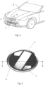
- reference numeral 1 denotes generally a decorative radome constructed in accordance with and embodying the invention configured for mounting within a grill assembly 2 of a motor vehicle 3.
- a radar antenna 4 Positioned within the vehicle 3 behind and in registration with the decorative radome 1 is a radar antenna 4.
- Fig. 2 shows a front view of the radome 1, where it is visible a radio transmissive colored layer 6 and a bright decoration layer 7 that provides the metal-looking appearance while keeping high transmittance performance for the signal emitted and received by the protected radar antenna 4.
- a first embodiment of the radome without air gaps is described with reference to Fig. 3 , where a schematical cross section of the radome 1 is shown.
- the position of the different layers within the radome 1 may be observed.
- the thickness of the different layers is not to scale because the relation between them is of orders of magnitude.
- the different layers will be described from the proximal face (closer to an external observer, at the right in this figure) to the distal face (closer to the radar 4, at the left in this figure).
- the radome 1 comprises a frontal transparent layer 5. It is made of a material with high transmissive capability to both the visible light and the signal emitted and received by the protected radar 4. It may be made of a plastic resin like Polycarbonate (PC) and may be obtained by injection molding or by cutting a laminated film of this material to the final desired shape.
- PC Polycarbonate
- the radome 1 also comprises a colored decoration layer 6 that provides opacity to the visible light while maintaining a high degree of transmission of the signal emitted and received by the protected radar 4. It partially covers one of the faces of the transparent layer 5, leaving some uncovered areas 11.
- This colored decoration layer 6 may be obtained by printing a decorative ink on a face of the transparent layer 5, which has been obtained by any of its mentioned manufacturing methods. This printing process requires the usage of a mask to leave some uncovered areas 11 by the colored decoration layer 6.
- the colored decoration layer 6 may also be obtained by injection molding in a manufacturing combined molding process with the transparent layer 5.
- the colored decoration layer 6 is represented on the distal face of the transparent layer 5. However, it may be located on its proximal face.
- the radome 1 according to the present invention also comprises a metal-looking decoration layer 7 that is deposited on the distal face (closer to the radar 4) of the set formed by the transparent layer 5 and the colored decoration layer 6.
- the colored decoration layer 6 may be seen by an external observer through the uncovered areas 11 of the colored decoration layer 6.
- the combination of opaque discontinuous areas of colored decoration layer 6 and metal-looking decoration layer 7 generates an emblem that may be seen by the external observer as shown on Fig. 2 .
- the metal-looking decoration layer 7 provides a bright appearance thanks to the usage of metals, metalloids and/or oxides. In any case, it must ensure high electrical resistivity to reduce the attenuation it causes to the signal emitted and received by the protected radar 4.
- This thin and controlled thickness layer may be deposited, for instance, by a Physical Vapor Deposition (PVD) magnetron sputtering process or by a Plasma Enhanced Chemical Vapor Deposition (PECVD) process, or others, depending on the composition of the layer.
- PVD Physical Vapor Deposition
- PECVD Plasma Enhanced Chemical Vapor Deposition
- composition and manufacturing process of the metal-looking decoration layer 7 does not offer a good adhesion to a rear layer 10 obtained by an insert molding process, some surface preparation on the metal-looking decoration layer 7 must be performed to improve it.
- the radome 1 according to the present invention also comprises an adhesion promoter layer 8 applied on the metal-looking decoration layer 7.
- This adhesion promoter layer 8 is bifunctional and generates a direct bonding between adjacent layers, not being an adhesive, which would generate independent bonding between the adhesive and each one of the layers to be bonded.
- This adhesion promoter layer 8 is very thin, so that it provides improved interfacial bonding characteristics, yet it is not so thick that its bulk properties significantly affect the overall properties of the bond.
- the adhesion promoter layer 8 may be conveniently applied by an air spray method thanks to its low viscosity (30 mPa ⁇ s maximum) forming a dried layer of a thickness of 20 ⁇ m maximum. Additionally, it dries in 30 to 90 seconds at room temperature. This is a much significant improvement compared to the acrylic two-component paint coat layers that usually require heat-drying in a chamber at 80 °C for 1 hour to volatilize the solvent or to the solvent-type adhesive agent coatings, which show viscosity of 500 mPa with drying times of 70 - 90 °C of during 0.5 - 3.5 hours.
- a polymer compatible ink layer 9 may be applied on the adhesion promoter layer 8.
- the ink layer 9 is composed of an ink used for applications on plastic parts of the same polymer than the raw material of the rear layer 10. It is similar to the ink that may be used to generate the colored decoration layer 6.
- the difference is its compatibility with the raw material of the rear layer 10 instead of being compatible with the raw material of the transparent layer 5.
- the fact of being an ink allows to dissolve it with a solvent which makes it compatible with an air spray method, with viscosities below 30 seconds when tested according to Viscosity Cup Ford-4 method.
- the dried layer may have a thickness of 30 ⁇ m maximum.
- this optional ink layer 9 may be based on the thermal sensitivity of the materials used for the metal-looking decoration layer 7.
- the rear layer 10 is applied at the most distal face by an insert molding process of the rest of layers described before.
- Its raw material may be Acrylonitrile butadiene styrene (ABS) or a blend of Polycarbonate and Acrylonitrile butadiene styrene (PC/ABS).
- the rear layer 10 provides a final protection to the internal decoration layers and usually contains the fixtures of the radome 1 to the rest of the car. It also offers additional opacity to visible light of the whole radome 1.
- an adhesion promoter layer 8 and, optionally, the ink layer 9 allows to adopt an insert molding manufacturing process. This ensures the absence of an air gap which may degrade the transmission capabilities of the radome or complicate the manufacturing process to achieve a minimum and constant air gap in the whole field of view of the radome.
- the achieved adhesion between layers also avoids that air gaps will be generated during thermal cycling of laboratory tests or life of the product.
- a hard coating consisting of a varnish may be applied on the proximal and or distal faces of the set of layers described until now.
- a second embodiment of the radome 1 without air gaps is described with reference to Fig. 4 .
- identical reference numerals are given to the components that are the same or similar to the corresponding components of the first embodiment and redundant description is omitted therein.
- a mask is applied to substantially cover the opaque areas defined by the colored decoration layer 6.
- the usage of such masking process is maintained during the deposition of the metal-looking decoration layer 7, the adhesion promoter layer 8 and the optional ink layer 9. This results in masked areas 12 which will be free of these layers when the mask is removed.
- the rear layer 10 is also manufactured by insert molding. Some areas of its proximal face will be in contact with the adhesion promoter layer 8 (or the ink layer 9, if it has been applied) and some other areas will be in contact with the set formed by the transparent layer 5 and the colored decoration layer 6.
- the masking process adds an additional step in the manufacturing process although improves the adhesion between the rear layer 10 and the rest of the radome 1.
Landscapes
- Engineering & Computer Science (AREA)
- Remote Sensing (AREA)
- Mechanical Engineering (AREA)
- Computer Networks & Wireless Communication (AREA)
- Physics & Mathematics (AREA)
- General Physics & Mathematics (AREA)
- Radar, Positioning & Navigation (AREA)
- Injection Moulding Of Plastics Or The Like (AREA)
- Laminated Bodies (AREA)
- Vehicle Interior And Exterior Ornaments, Soundproofing, And Insulation (AREA)
- Details Of Aerials (AREA)
Priority Applications (5)
| Application Number | Priority Date | Filing Date | Title |
|---|---|---|---|
| EP21382696.9A EP4124879A1 (en) | 2021-07-27 | 2021-07-27 | Radome for vehicles |
| EP22186389.7A EP4124880A1 (en) | 2021-07-27 | 2022-07-22 | Radome for vehicles and method for manufacturing said radome |
| US17/815,174 US20230032918A1 (en) | 2021-07-27 | 2022-07-26 | Radome for vehicles and method for manufacturing said radome |
| JP2022119475A JP2023018675A (ja) | 2021-07-27 | 2022-07-27 | 車両用レードーム及び当該レードームを製造するための方法 |
| CN202210890039.XA CN115693135A (zh) | 2021-07-27 | 2022-07-27 | 车辆雷达罩及用于制造所述雷达罩的方法 |
Applications Claiming Priority (1)
| Application Number | Priority Date | Filing Date | Title |
|---|---|---|---|
| EP21382696.9A EP4124879A1 (en) | 2021-07-27 | 2021-07-27 | Radome for vehicles |
Publications (1)
| Publication Number | Publication Date |
|---|---|
| EP4124879A1 true EP4124879A1 (en) | 2023-02-01 |
Family
ID=77168172
Family Applications (2)
| Application Number | Title | Priority Date | Filing Date |
|---|---|---|---|
| EP21382696.9A Withdrawn EP4124879A1 (en) | 2021-07-27 | 2021-07-27 | Radome for vehicles |
| EP22186389.7A Pending EP4124880A1 (en) | 2021-07-27 | 2022-07-22 | Radome for vehicles and method for manufacturing said radome |
Family Applications After (1)
| Application Number | Title | Priority Date | Filing Date |
|---|---|---|---|
| EP22186389.7A Pending EP4124880A1 (en) | 2021-07-27 | 2022-07-22 | Radome for vehicles and method for manufacturing said radome |
Country Status (4)
| Country | Link |
|---|---|
| US (1) | US20230032918A1 (https=) |
| EP (2) | EP4124879A1 (https=) |
| JP (1) | JP2023018675A (https=) |
| CN (1) | CN115693135A (https=) |
Families Citing this family (2)
| Publication number | Priority date | Publication date | Assignee | Title |
|---|---|---|---|---|
| EP4451460A1 (en) | 2023-04-21 | 2024-10-23 | Zanini Auto Grup, S.A. | Radome for vehicles and method for manufacturing said radome for vehicles |
| EP4653259A1 (en) * | 2024-05-21 | 2025-11-26 | HELLA Saturnus Slovenija d.o.o. | Illuminated trim part of or for a vehicle and method for producing such an illuminated trim part |
Citations (6)
| Publication number | Priority date | Publication date | Assignee | Title |
|---|---|---|---|---|
| US7990334B2 (en) | 2007-06-13 | 2011-08-02 | Toyoda Gosei Co., Ltd. | Radio wave transmission cover and method of manufacturing radio wave transmission cover |
| EP2383364A1 (en) * | 2009-01-20 | 2011-11-02 | Shin-Etsu Polymer Co. Ltd. | Radio wave-transmitting decorative member and method for producing same |
| CN103367913A (zh) | 2012-04-06 | 2013-10-23 | 湖州赫特金泰汽车零部件有限公司 | 一种雷达保护罩的制造方法 |
| EP3529857A1 (en) | 2016-10-24 | 2019-08-28 | Zanini Auto Grup, S.A. | Radome for vehicles |
| DE102018221971A1 (de) * | 2018-12-17 | 2020-06-18 | Psa Automobiles Sa | Kraftfahrzeug Sende- und/oder Empfangseinheit |
| WO2021018422A1 (en) * | 2019-07-29 | 2021-02-04 | Motherson Innovations Company Ltd. | First surface or second surface decorative radome |
Family Cites Families (2)
| Publication number | Priority date | Publication date | Assignee | Title |
|---|---|---|---|---|
| US5985198A (en) * | 1997-07-30 | 1999-11-16 | Ford Motor Company | Method for molding a film-covered article |
| JP6467985B2 (ja) * | 2015-02-25 | 2019-02-13 | 豊田合成株式会社 | 電磁波透過カバーの製造方法 |
-
2021
- 2021-07-27 EP EP21382696.9A patent/EP4124879A1/en not_active Withdrawn
-
2022
- 2022-07-22 EP EP22186389.7A patent/EP4124880A1/en active Pending
- 2022-07-26 US US17/815,174 patent/US20230032918A1/en active Pending
- 2022-07-27 JP JP2022119475A patent/JP2023018675A/ja active Pending
- 2022-07-27 CN CN202210890039.XA patent/CN115693135A/zh active Pending
Patent Citations (6)
| Publication number | Priority date | Publication date | Assignee | Title |
|---|---|---|---|---|
| US7990334B2 (en) | 2007-06-13 | 2011-08-02 | Toyoda Gosei Co., Ltd. | Radio wave transmission cover and method of manufacturing radio wave transmission cover |
| EP2383364A1 (en) * | 2009-01-20 | 2011-11-02 | Shin-Etsu Polymer Co. Ltd. | Radio wave-transmitting decorative member and method for producing same |
| CN103367913A (zh) | 2012-04-06 | 2013-10-23 | 湖州赫特金泰汽车零部件有限公司 | 一种雷达保护罩的制造方法 |
| EP3529857A1 (en) | 2016-10-24 | 2019-08-28 | Zanini Auto Grup, S.A. | Radome for vehicles |
| DE102018221971A1 (de) * | 2018-12-17 | 2020-06-18 | Psa Automobiles Sa | Kraftfahrzeug Sende- und/oder Empfangseinheit |
| WO2021018422A1 (en) * | 2019-07-29 | 2021-02-04 | Motherson Innovations Company Ltd. | First surface or second surface decorative radome |
Also Published As
| Publication number | Publication date |
|---|---|
| JP2023018675A (ja) | 2023-02-08 |
| US20230032918A1 (en) | 2023-02-02 |
| CN115693135A (zh) | 2023-02-03 |
| EP4124880A1 (en) | 2023-02-01 |
Similar Documents
| Publication | Publication Date | Title |
|---|---|---|
| EP3867975B1 (en) | Decorative radome and method of producing the same | |
| EP4124879A1 (en) | Radome for vehicles | |
| US6184842B1 (en) | Process for manufacturing a radome for a range warning radar | |
| JP2022542791A (ja) | 第1表面または第2表面装飾レドーム | |
| US20140093665A1 (en) | Decorative member for vehicle | |
| EP3958397B1 (en) | Radome for vehicles | |
| CN112216974A (zh) | 用于汽车车辆应用的装饰性天线罩 | |
| US20170324157A1 (en) | Three piece vehicle radome | |
| KR20170047070A (ko) | 고휘도 도료를 이용한 레이돔 및 이를 포함하는 자동차 | |
| US20240162603A1 (en) | Radome for vehicles | |
| US20240356206A1 (en) | Radome for vehicles and method for manufacturing said radome for vehicles | |
| CN113544529A (zh) | 雷达罩 | |
| US20130214555A1 (en) | Adhesively Bonded Window and Hardware Assembly | |
| JP2008024254A (ja) | 車両の外装部品及びその製造方法 | |
| US8372493B2 (en) | Emblem assembly and method of forming same | |
| US12030285B2 (en) | Decorative functional component having a transparent partial surface | |
| US7789457B2 (en) | Vehicle film component, and method for the production thereof | |
| KR102320784B1 (ko) | 전파 송수신 레이더 전파 투과형 커버 | |
| KR20190011527A (ko) | 자동차 제어를 위한 전파 투과형 광학 커버 및 그 제조방법 | |
| JP2020180859A (ja) | レーダカバー及びレーダカバーの製造方法 | |
| EP4660661A1 (en) | License plate radar system | |
| US12202414B2 (en) | Decorative element for vehicle with camera | |
| KR102190898B1 (ko) | 전파 송수신 레이더 전파 투과형 커버 및 그 제조방법 | |
| US20140120273A1 (en) | Method for preventing galvanic and chemical corrosion in emblems containing second surface decoration and metallization and method of making and using the same |
Legal Events
| Date | Code | Title | Description |
|---|---|---|---|
| PUAI | Public reference made under article 153(3) epc to a published international application that has entered the european phase |
Free format text: ORIGINAL CODE: 0009012 |
|
| STAA | Information on the status of an ep patent application or granted ep patent |
Free format text: STATUS: THE APPLICATION HAS BEEN PUBLISHED |
|
| AK | Designated contracting states |
Kind code of ref document: A1 Designated state(s): AL AT BE BG CH CY CZ DE DK EE ES FI FR GB GR HR HU IE IS IT LI LT LU LV MC MK MT NL NO PL PT RO RS SE SI SK SM TR |
|
| STAA | Information on the status of an ep patent application or granted ep patent |
Free format text: STATUS: THE APPLICATION IS DEEMED TO BE WITHDRAWN |
|
| 18D | Application deemed to be withdrawn |
Effective date: 20230802 |