EP4124869B1 - Stromwandler - Google Patents
Stromwandler Download PDFInfo
- Publication number
- EP4124869B1 EP4124869B1 EP21188975.3A EP21188975A EP4124869B1 EP 4124869 B1 EP4124869 B1 EP 4124869B1 EP 21188975 A EP21188975 A EP 21188975A EP 4124869 B1 EP4124869 B1 EP 4124869B1
- Authority
- EP
- European Patent Office
- Prior art keywords
- magnetic core
- magnetic
- housing
- current transducer
- lateral branches
- Prior art date
- Legal status (The legal status is an assumption and is not a legal conclusion. Google has not performed a legal analysis and makes no representation as to the accuracy of the status listed.)
- Active
Links
Images


Classifications
-
- G—PHYSICS
- G01—MEASURING; TESTING
- G01R—MEASURING ELECTRIC VARIABLES; MEASURING MAGNETIC VARIABLES
- G01R15/00—Details of measuring arrangements of the types provided for in groups G01R17/00 - G01R29/00, G01R33/00 - G01R33/26 or G01R35/00
- G01R15/14—Adaptations providing voltage or current isolation, e.g. for high-voltage or high-current networks
- G01R15/20—Adaptations providing voltage or current isolation, e.g. for high-voltage or high-current networks using galvano-magnetic devices, e.g. Hall-effect devices, i.e. measuring a magnetic field via the interaction between a current and a magnetic field, e.g. magneto resistive or Hall effect devices
- G01R15/207—Constructional details independent of the type of device used
-
- G—PHYSICS
- G01—MEASURING; TESTING
- G01R—MEASURING ELECTRIC VARIABLES; MEASURING MAGNETIC VARIABLES
- G01R15/00—Details of measuring arrangements of the types provided for in groups G01R17/00 - G01R29/00, G01R33/00 - G01R33/26 or G01R35/00
- G01R15/14—Adaptations providing voltage or current isolation, e.g. for high-voltage or high-current networks
- G01R15/18—Adaptations providing voltage or current isolation, e.g. for high-voltage or high-current networks using inductive devices, e.g. transformers
- G01R15/183—Adaptations providing voltage or current isolation, e.g. for high-voltage or high-current networks using inductive devices, e.g. transformers using transformers with a magnetic core
-
- G—PHYSICS
- G01—MEASURING; TESTING
- G01R—MEASURING ELECTRIC VARIABLES; MEASURING MAGNETIC VARIABLES
- G01R19/00—Arrangements for measuring currents or voltages or for indicating presence or sign thereof
- G01R19/0092—Arrangements for measuring currents or voltages or for indicating presence or sign thereof measuring current only
-
- G—PHYSICS
- G01—MEASURING; TESTING
- G01R—MEASURING ELECTRIC VARIABLES; MEASURING MAGNETIC VARIABLES
- G01R1/00—Details of instruments or arrangements of the types included in groups G01R5/00 - G01R13/00 and G01R31/00
- G01R1/20—Modifications of basic electric elements for use in electric measuring instruments; Structural combinations of such elements with such instruments
- G01R1/22—Tong testers acting as secondary windings of current transformers
Definitions
- the present invention relates to a current transducer with a magnetic core surrounding a central passage configured for receiving one or more primary conductors for measuring a current flowing in said one or more conductors.
- a well-known type of current transducer comprises a magnetic core with an airgap in which a magnetic field detector, such as a Hall effect sensor is positioned to measure the magnetic field generated by the current flowing in the primary conductor.
- a magnetic field detector such as a Hall effect sensor
- Such transducers may be of the open loop type or the closed loop type, the latter typically having a compensation coil that generates a secondary current seeking to cancel the magnetic field generated by the primary current to be measured.
- the airgaps and magnetic field detectors there are two airgaps and two magnetic field detectors, one in each airgap.
- the airgaps and magnetic field detectors are typically provided on opposed sides of the magnetic circuit in a symmetrical arrangement.
- One of the advantages of providing a pair of airgaps is to provide the magnetic core in two parts, typically two U-shaped parts that may be separated to allow a primary conductor to be positioned within the central passage surrounded by the magnetic core when they are assembled together.
- Two part magnetic cores with only one airgap within which a magnetic field detector is positioned are also known, however greater measurement sensitivity and accuracy with reduced saturation of the magnetic is achievable with two part magnetic cores having two airgaps, each with a magnetic field detector.
- GB 825137 A discloses an electrical current measuring apparatus.
- an electric current transducer comprising a housing, a magnetic core and a magnetic field detection system, the magnetic core surrounding a primary conductor passage for receiving a primary conductor therethrough.
- the magnetic core comprises a first part and a second part assembled in the housing so as to form a first magnetic circuit gap and a second magnetic circuit gap, the magnetic field detection system comprising a first magnetic field detector positioned in the first magnetic circuit gap and a second magnetic field detector positioned in the second magnetic circuit gap.
- the first and second magnetic circuit gaps are disposed on opposing sides of magnetic core, each of the first and second parts comprising a pair of lateral branches, joined by a bridging branch.
- the lateral branches of the first and second magnetic core parts overlap such that the lateral branches of the first part of the magnetic core are positioned adjacent an inner side of the lateral branches of the second part of the magnetic core, said first and second magnetic circuit gaps being formed between an outer side of the lateral branches of the first part and an inner side of the lateral branches of second part.
- the magnetic core first part and second part are both U-shaped.
- the housing comprises a base housing and a cover housing movable with respect to the base housing from an open position in which the primary conductor can be placed in the primary conductor passage, to a closed and locked position in which the magnetic core completely surrounds the primary conductor passage, one of the first and second parts of the magnetic core being mounted in the base and the other of the first and second parts of the magnetic core being mounted in the cover.
- the cover housing is hingeably coupled to the base housing.
- the cover housing is removably coupled to the base housing.
- the lateral branches of the magnetic core first part are received in corresponding cavities in the base housing, the magnetic field detectors being mounted in said same cavities:
- the magnetic core receiving portions comprises outer guide walls for lateral branches having an outer surface guiding a complementary guide walls for lateral branches on the cover housing in the closed position.
- the guide walls are tapered.
- the first part of the magnetic core is positioned in the base housing and the second part of the magnetic core positioned in the cover housing.
- the magnetic field detectors are in the form of ASICs mounted on a circuit board of an electronic circuit mounted in the base housing.
- the ASICs are arranged upstanding orthogonally from the circuit board when positioned in corresponding cavities of the housing in abutment against the corresponding lateral branches of the first part of the magnetic core.
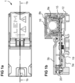
- an electric current transducer 1 for measuring a current in one or more primary conductors 3 comprises a housing 2, a magnetic core 15, 16, a magnetic field detection system 18a, 18b, and an electronic circuit 21 mounted within the housing.
- the housing 2 has a primary conductor receiving portion defining a primary conductor passage 4 for receiving the one or more primary conductors therethrough.
- the magnetic core comprises a first part 15 and a second part 16 that define a first magnetic circuit gap 17a and a second magnetic circuit gap 17b between the first and second parts 15 and 16 of the magnetic core.
- the magnetic field detection system comprises a first magnetic field detector 18a mounted within the first magnetic circuit gap and a second magnetic field detector 18b mounted within the second magnetic circuit gap 17b.
- a magnetic circuit gap is also commonly known as an "airgap" even though the gap may be filled with non-magnetic materials other than air.
- the magnetic field detectors may be Hall effect detectors, fluxgate detectors or other forms of magnetic field detectors per se well known in the art. Magnetic field detectors may advantageously be provided in the form of an ASIC (Application Specific Integrated Circuit) that is mounted and connected to a circuit board 19 of the electronic circuit 21.
- ASIC Application Specific Integrated Circuit
- the electronic circuit may further comprise a connector 20 for electrical connection to an external circuit to which the transducer is connected in use.
- the electronic circuit may comprise further circuit components on the circuit board 19 to process the signal from the magnetic field detectors 18a, 18b and provide power thereto. Such functions are per se well known and do not need to be further described herein.
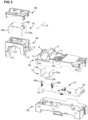
- the housing comprises a base housing 5 within which the electronic circuit 21 and the first part 15 of the magnetic core are received.
- the housing 2 further comprises a cover housing 8 within which the second part 16 of the magnetic core is mounted, the cover housing 8 being coupled to be base housing 5.
- the base housing 5 comprises a first housing member 5a and the second housing member 5b that are assembled together and form one or more cavities therein to receive and lodge the electronic circuit and the first part 15 of the magnetic core.
- the second housing member 5b comprises in particular a magnetic core receiving portion 6 having cavities for lodging and positioning lateral branches 15a of the magnetic core first part 15. Within the lodging cavities, the magnetic field detectors 18a, 18b are also received adjacent an outer side of the lateral branches 15a.
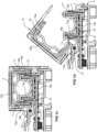
- the magnetic core first part 15 and second part 16 may be generally U-shaped, comprising lateral branches 15a, 16a interconnected by a bridging branch 15b.
- the lateral branches 15a of the first part 15 are spaced apart less than the lateral branches 16a of the second part, such that the lateral branches of the first part may be positioned within the space formed between the lateral branches 16 of the second part.
- an airgap 17a is formed between an outer side of a lateral branch 15a of the first part and an inner side of a lateral branch 16a of the second part.
- the U-shapes of the first and second parts are arranged in an opposing manner to form the central passage therebetween with the lateral branches overlapping each other to form the airgaps between outer and inner lateral sides of the respective branches.
- one of the airgaps will have a length G1 that reduces while the other airgap will have a length G2 that increases.
- the sum of the airgaps G1 plus G2 thus remains constant.
- An important advantage of this configuration is the reduced variation in the measurement of the magnetic field when summing outputs of the first and second magnetic field detectors compared to a conventional transducer where the airgaps are provided between opposing ends of the lateral branches arranged in mirror symmetry.
- a shift in the position between the first and second magnetic core parts may change the length of both airgaps. Inaccuracies due to positional variations in the position of the magnetic core parts are thus present without any mitigating effect.
- the magnetic core receiving portion 6 of the base housing 5 may advantageously comprise guide walls 7 on outer lateral sides of the receiving cavities 22 forming a guide surface 11 on an outer lateral side cooperating with the lateral branches 16a of the second part or guide walls on the cover housing 8 for positioning the lateral branches 16a of the second part 16 on outer side of the lateral branches 15 of the first part of the magnetic core.
- the guide walls 7 may advantageously have a tapered guide surface 11 at the upper ends to guide and position the cover as it is pivoted to the closed position.
- the cover housing 8 may be coupled to the base housing 5 via a pivot coupling for instance comprising a pin 14 received in complementary holes in pivot lugs 13 of the cover housing, allowing the cover housing to be pivotally opened to receive a primary conductor in the primary conductor passage 4, as best seen in figure 1d .
- the cover housing can then be pivoted back the closed position where a latch 12 for instance clips on to the base housing 5 to secure to cover housing to the base housing in a closed position as best seen in figure 1c .
- the cover housing may be completely removable from the base housing and fixed together with a pair of latches, instead of having a pivot mechanism.
- Other coupling mechanisms for disassembly and assembly of the cover and base housings for opening the central passage to position a primary conductor therein may be provided.
- An important advantage of the invention configuration in which the lateral branches overlap to form two airgaps is not only the reduced effect of inaccuracies in the relative lateral positioning, but also the reduced effect of inaccuracies in the spacing between the core parts, since whether the bridging branches are closer or further apart there is no change in the size of the airgap.
Landscapes
- Physics & Mathematics (AREA)
- General Physics & Mathematics (AREA)
- Engineering & Computer Science (AREA)
- Power Engineering (AREA)
- Measuring Instrument Details And Bridges, And Automatic Balancing Devices (AREA)
Claims (11)
- Elektrischer Stromwandler (1), der ein Gehäuse (2), einen Magnetkern und ein Magnetfelddetektionssystem umfasst, wobei der Magnetkern eine primäre Leiterdurchführung (4) zum Aufnehmen eines primären Leiters (30) dadurch umgibt, wobei der Magnetkern einen ersten Teil (15) und einen zweiten Teil (16) umfasst, die im Gehäuse derart zusammengesetzt sind, dass sie einen ersten Magnetkreisspalt (17a) und einen zweiten Magnetkreisspalt (17b) bilden, wobei das Magnetfelddetektionssystem einen ersten Magnetfelddetektor (18a), der im ersten Magnetkreisspalt (17a) positioniert ist, und einen zweiten Magnetfelddetektor (18b), der im zweiten Magnetkreisspalt (17b) positioniert ist, umfasst, wobei der erste und der zweite Magnetkreisspalt auf gegenüberliegenden Seiten des Magnetkerns angeordnet sind, wobei jeder des ersten und des zweiten Teils ein Paar von seitlichen Verzweigungen (15a, 16a) umfasst, die durch eine Überbrückungsverzweigung (15b, 16b) verbunden sind, dadurch gekennzeichnet, dass die seitlichen Verzweigungen des ersten und des zweiten Magnetkernteils derart überlappen, dass die seitlichen Verzweigungen (15a) des ersten Teils (15) des Magnetkerns neben einer Innenseite der seitlichen Verzweigungen (16a) des zweiten Teils (16) des Magnetkerns positioniert sind, wobei der erste und der zweite Magnetkreisspalt zwischen einer Außenseite der seitlichen Verzweigungen des ersten Teils und einer Innenseite der seitlichen Verzweigungen des zweiten Teils gebildet sind.
- Stromwandler nach Anspruch 1, wobei der erste Teil und der zweite Teil des Magnetkerns jeweils U-förmig sind.
- Stromwandler nach einem der vorhergehenden Ansprüche, wobei das Gehäuse ein Basisgehäuse (5) und ein Abdeckungsgehäuse (8) umfasst, das mit Bezug auf das Basisgehäuse von einer offenen Position, in der der primäre Leiter (30) in der primären Leiterdurchführung (4) platziert werden kann, zu einer geschlossenen und verriegelten Position, in der der Magnetkern die primäre Leiterdurchführung (4) vollständig umgibt, bewegbar ist, wobei einer des ersten und des zweiten Teils des Magnetkerns in der Basis montiert ist und der andere des ersten und des zweiten Teils des Magnetkerns in der Abdeckung montiert ist.
- Stromwandler nach einem der vorhergehenden Ansprüche, wobei das Abdeckungsgehäuse (8) gelenkig an das Basisgehäuse (5) gekoppelt ist.
- Stromwandler nach einem der vorhergehenden Ansprüche 1-4, wobei das Abdeckungsgehäuse (8) entfernbar an das Basisgehäuse (5) gekoppelt ist.
- Stromwandler nach einem der vorhergehenden Ansprüche, wobei die seitlichen Verzweigungen (15a) des ersten Magnetkernteils (15) in entsprechende Hohlräume im Basisgehäuse aufgenommen sind, wobei die Magnetfelddetektoren in denselben Hohlräumen montiert sind:
- Stromwandler nach einem der vorhergehenden Ansprüche, wobei die Aufnahmeabschnitte (6) des Magnetkerns Außenführungswände für seitliche Verzweigungen (7) umfassen, die eine Außenfläche (11) aufweisen, die eine komplementäre Führungswände für seitliche Verzweigungen auf dem Abdeckungsgehäuse in die geschlossene Position führt.
- Stromwandler nach dem vorhergehenden Anspruch, wobei die Führungswände konisch sind.
- Stromwandler nach einem der vorhergehenden Ansprüche, wobei der erste Teil des Magnetkerns im Basisgehäuse (5) positioniert ist und der zweite Teil (16) des Magnetkerns im Abdeckungsgehäuse (8) positioniert ist.
- Stromwandler nach einem der vorhergehenden Ansprüche, wobei die Magnetfelddetektoren (18a, 18b) die Form von ASICs aufweisen, die auf einer Leiterplatte (19) einer elektronischen Schaltung montiert sind, die im Basisgehäuse (5) montiert ist.
- Stromwandler nach dem vorhergehenden Anspruch, wobei die ASICs aufrecht orthogonal von der Leiterplatte (19) angebracht sind, wenn sie in entsprechenden Hohlräumen des Gehäuses an den entsprechenden seitlichen Verzweigungen des ersten Teils des Magnetkerns anliegend positioniert sind.
Priority Applications (5)
| Application Number | Priority Date | Filing Date | Title |
|---|---|---|---|
| EP21188975.3A EP4124869B1 (de) | 2021-07-31 | 2021-07-31 | Stromwandler |
| JP2024505599A JP7665864B2 (ja) | 2021-07-31 | 2022-07-19 | 電流変換器 |
| US18/293,401 US12203963B2 (en) | 2021-07-31 | 2022-07-19 | Current transducer |
| CN202280050083.8A CN117642641B (zh) | 2021-07-31 | 2022-07-19 | 电流传感器 |
| PCT/EP2022/070270 WO2023011916A1 (en) | 2021-07-31 | 2022-07-19 | Current transducer |
Applications Claiming Priority (1)
| Application Number | Priority Date | Filing Date | Title |
|---|---|---|---|
| EP21188975.3A EP4124869B1 (de) | 2021-07-31 | 2021-07-31 | Stromwandler |
Publications (3)
| Publication Number | Publication Date |
|---|---|
| EP4124869A1 EP4124869A1 (de) | 2023-02-01 |
| EP4124869C0 EP4124869C0 (de) | 2023-10-11 |
| EP4124869B1 true EP4124869B1 (de) | 2023-10-11 |
Family
ID=77168036
Family Applications (1)
| Application Number | Title | Priority Date | Filing Date |
|---|---|---|---|
| EP21188975.3A Active EP4124869B1 (de) | 2021-07-31 | 2021-07-31 | Stromwandler |
Country Status (5)
| Country | Link |
|---|---|
| US (1) | US12203963B2 (de) |
| EP (1) | EP4124869B1 (de) |
| JP (1) | JP7665864B2 (de) |
| CN (1) | CN117642641B (de) |
| WO (1) | WO2023011916A1 (de) |
Family Cites Families (19)
| Publication number | Priority date | Publication date | Assignee | Title |
|---|---|---|---|---|
| GB825137A (en) * | 1955-07-14 | 1959-12-09 | Siemens Ag | Improvements in or relating to an electrical current measuring apparatus |
| JP3317681B2 (ja) | 1999-03-31 | 2002-08-26 | 大崎電気工業株式会社 | 電流−磁気変換回路 |
| EP1811311B1 (de) * | 2006-01-19 | 2016-08-31 | Melexis Technologies NV | Vorrichtung zur Strommessung |
| JP4861155B2 (ja) * | 2006-12-20 | 2012-01-25 | 矢崎総業株式会社 | 電流センサ及びその成形方法 |
| ATE494558T1 (de) * | 2008-01-25 | 2011-01-15 | Lem Liaisons Electron Mec | Stromsensor |
| JP2011158337A (ja) * | 2010-01-29 | 2011-08-18 | Aichi Micro Intelligent Corp | 電流センサ |
| DE102011080041A1 (de) * | 2011-07-28 | 2013-04-11 | Vacuumschmelze Gmbh & Co. Kg | Stromsensoranordnung |
| US8587399B2 (en) * | 2012-02-06 | 2013-11-19 | Continental Control Systems, Llc | Split-core current transformer |
| JP2013228315A (ja) | 2012-04-26 | 2013-11-07 | Tdk Corp | 電流センサ |
| WO2013161496A1 (ja) * | 2012-04-27 | 2013-10-31 | アルプス・グリーンデバイス株式会社 | 電流センサ |
| JP2015068824A (ja) | 2013-09-27 | 2015-04-13 | 甲神電機株式会社 | 導体及びこれを備えた電流センサ |
| EP2853904A1 (de) * | 2013-09-30 | 2015-04-01 | LEM Intellectual Property SA | Aufklemmbarer Stromwandler oder Stromtransformator |
| EP2921865A1 (de) * | 2014-03-21 | 2015-09-23 | LEM Intellectual Property SA | Magnetfeldsensoranordnung und Stromwandler damit |
| JP6361740B2 (ja) | 2014-11-14 | 2018-07-25 | 株式会社村田製作所 | 電流センサ |
| EP3159705A1 (de) * | 2015-10-23 | 2017-04-26 | LEM Intellectual Property SA | Stromwandler mit integriertem primärem leiter |
| JP2018189504A (ja) | 2017-05-08 | 2018-11-29 | 矢崎総業株式会社 | 電流センサ |
| US11768228B2 (en) * | 2019-07-11 | 2023-09-26 | Sense Labs, Inc. | Current transformer with calibration information |
| JP7536662B2 (ja) | 2020-03-06 | 2024-08-20 | 日置電機株式会社 | 電流センサ |
| JP7215451B2 (ja) * | 2020-03-19 | 2023-01-31 | Tdk株式会社 | 電流センサ及びその製造方法、電気制御装置、並びに電流センサの設計方法 |
-
2021
- 2021-07-31 EP EP21188975.3A patent/EP4124869B1/de active Active
-
2022
- 2022-07-19 US US18/293,401 patent/US12203963B2/en active Active
- 2022-07-19 WO PCT/EP2022/070270 patent/WO2023011916A1/en not_active Ceased
- 2022-07-19 JP JP2024505599A patent/JP7665864B2/ja active Active
- 2022-07-19 CN CN202280050083.8A patent/CN117642641B/zh active Active
Also Published As
| Publication number | Publication date |
|---|---|
| US12203963B2 (en) | 2025-01-21 |
| JP7665864B2 (ja) | 2025-04-21 |
| EP4124869C0 (de) | 2023-10-11 |
| EP4124869A1 (de) | 2023-02-01 |
| JP2024527122A (ja) | 2024-07-19 |
| WO2023011916A1 (en) | 2023-02-09 |
| CN117642641A (zh) | 2024-03-01 |
| US20240264203A1 (en) | 2024-08-08 |
| CN117642641B (zh) | 2024-09-03 |
Similar Documents
| Publication | Publication Date | Title |
|---|---|---|
| US6459255B1 (en) | Current detector | |
| US20120126789A1 (en) | Rogowski current sensor | |
| US10295574B2 (en) | Clip-on current transducer or current transformer | |
| CN103959073A (zh) | 电流传感器 | |
| US20070044370A1 (en) | Coil, coil module and method of manufacturing the same, current sensor and method of manufacturing the same | |
| JP2012073277A (ja) | 電流センサー | |
| JP2002213906A (ja) | 電磁誘導型絶対位置トランスデューサ | |
| EP3405795A1 (de) | Messvorrichtung | |
| EP4235192B1 (de) | Stromwandler mit magnetfeldgradientensensor | |
| US20100090685A1 (en) | Wide-range open-loop current sensor | |
| US20030155905A1 (en) | Device, amperemeter and motor vehicle | |
| EP4124869B1 (de) | Stromwandler | |
| KR20200138048A (ko) | 전류센서 | |
| JP2010088011A (ja) | 方向性結合器 | |
| JP7553018B2 (ja) | 電流センサ及び電力量計 | |
| JPH0750658B2 (ja) | 電流変成器 | |
| JP2958796B2 (ja) | 零相電流測定用センサ | |
| JPH022544B2 (de) | ||
| JP2002107384A (ja) | 電流センサ | |
| JP2002277491A (ja) | 電流センサ | |
| EP4459293B1 (de) | Stromwandlermodul | |
| JPS61200477A (ja) | 電流測定装置 | |
| CN120826613A (zh) | 具有差分磁场换能器的电流传感器 | |
| CN120077282A (zh) | 电流传感器 | |
| RU1500055C (ru) | Датчик магнитного поля |
Legal Events
| Date | Code | Title | Description |
|---|---|---|---|
| PUAI | Public reference made under article 153(3) epc to a published international application that has entered the european phase |
Free format text: ORIGINAL CODE: 0009012 |
|
| STAA | Information on the status of an ep patent application or granted ep patent |
Free format text: STATUS: THE APPLICATION HAS BEEN PUBLISHED |
|
| AK | Designated contracting states |
Kind code of ref document: A1 Designated state(s): AL AT BE BG CH CY CZ DE DK EE ES FI FR GB GR HR HU IE IS IT LI LT LU LV MC MK MT NL NO PL PT RO RS SE SI SK SM TR |
|
| STAA | Information on the status of an ep patent application or granted ep patent |
Free format text: STATUS: REQUEST FOR EXAMINATION WAS MADE |
|
| 17P | Request for examination filed |
Effective date: 20230327 |
|
| RBV | Designated contracting states (corrected) |
Designated state(s): AL AT BE BG CH CY CZ DE DK EE ES FI FR GB GR HR HU IE IS IT LI LT LU LV MC MK MT NL NO PL PT RO RS SE SI SK SM TR |
|
| GRAP | Despatch of communication of intention to grant a patent |
Free format text: ORIGINAL CODE: EPIDOSNIGR1 |
|
| STAA | Information on the status of an ep patent application or granted ep patent |
Free format text: STATUS: GRANT OF PATENT IS INTENDED |
|
| INTG | Intention to grant announced |
Effective date: 20230522 |
|
| RAP3 | Party data changed (applicant data changed or rights of an application transferred) |
Owner name: LEM INTERNATIONAL SA |
|
| GRAS | Grant fee paid |
Free format text: ORIGINAL CODE: EPIDOSNIGR3 |
|
| GRAA | (expected) grant |
Free format text: ORIGINAL CODE: 0009210 |
|
| STAA | Information on the status of an ep patent application or granted ep patent |
Free format text: STATUS: THE PATENT HAS BEEN GRANTED |
|
| AK | Designated contracting states |
Kind code of ref document: B1 Designated state(s): AL AT BE BG CH CY CZ DE DK EE ES FI FR GB GR HR HU IE IS IT LI LT LU LV MC MK MT NL NO PL PT RO RS SE SI SK SM TR |
|
| REG | Reference to a national code |
Ref country code: GB Ref legal event code: FG4D |
|
| REG | Reference to a national code |
Ref country code: CH Ref legal event code: EP |
|
| REG | Reference to a national code |
Ref country code: DE Ref legal event code: R096 Ref document number: 602021005768 Country of ref document: DE |
|
| REG | Reference to a national code |
Ref country code: IE Ref legal event code: FG4D |
|
| U01 | Request for unitary effect filed |
Effective date: 20231011 |
|
| U07 | Unitary effect registered |
Designated state(s): AT BE BG DE DK EE FI FR IT LT LU LV MT NL PT SE SI Effective date: 20231019 |
|
| PG25 | Lapsed in a contracting state [announced via postgrant information from national office to epo] |
Ref country code: GR Free format text: LAPSE BECAUSE OF FAILURE TO SUBMIT A TRANSLATION OF THE DESCRIPTION OR TO PAY THE FEE WITHIN THE PRESCRIBED TIME-LIMIT Effective date: 20240112 |
|
| PG25 | Lapsed in a contracting state [announced via postgrant information from national office to epo] |
Ref country code: IS Free format text: LAPSE BECAUSE OF FAILURE TO SUBMIT A TRANSLATION OF THE DESCRIPTION OR TO PAY THE FEE WITHIN THE PRESCRIBED TIME-LIMIT Effective date: 20240211 |
|
| PG25 | Lapsed in a contracting state [announced via postgrant information from national office to epo] |
Ref country code: ES Free format text: LAPSE BECAUSE OF FAILURE TO SUBMIT A TRANSLATION OF THE DESCRIPTION OR TO PAY THE FEE WITHIN THE PRESCRIBED TIME-LIMIT Effective date: 20231011 |
|
| PG25 | Lapsed in a contracting state [announced via postgrant information from national office to epo] |
Ref country code: IS Free format text: LAPSE BECAUSE OF FAILURE TO SUBMIT A TRANSLATION OF THE DESCRIPTION OR TO PAY THE FEE WITHIN THE PRESCRIBED TIME-LIMIT Effective date: 20240211 Ref country code: GR Free format text: LAPSE BECAUSE OF FAILURE TO SUBMIT A TRANSLATION OF THE DESCRIPTION OR TO PAY THE FEE WITHIN THE PRESCRIBED TIME-LIMIT Effective date: 20240112 Ref country code: ES Free format text: LAPSE BECAUSE OF FAILURE TO SUBMIT A TRANSLATION OF THE DESCRIPTION OR TO PAY THE FEE WITHIN THE PRESCRIBED TIME-LIMIT Effective date: 20231011 |
|
| PG25 | Lapsed in a contracting state [announced via postgrant information from national office to epo] |
Ref country code: RS Free format text: LAPSE BECAUSE OF FAILURE TO SUBMIT A TRANSLATION OF THE DESCRIPTION OR TO PAY THE FEE WITHIN THE PRESCRIBED TIME-LIMIT Effective date: 20231011 Ref country code: PL Free format text: LAPSE BECAUSE OF FAILURE TO SUBMIT A TRANSLATION OF THE DESCRIPTION OR TO PAY THE FEE WITHIN THE PRESCRIBED TIME-LIMIT Effective date: 20231011 Ref country code: NO Free format text: LAPSE BECAUSE OF FAILURE TO SUBMIT A TRANSLATION OF THE DESCRIPTION OR TO PAY THE FEE WITHIN THE PRESCRIBED TIME-LIMIT Effective date: 20240111 Ref country code: HR Free format text: LAPSE BECAUSE OF FAILURE TO SUBMIT A TRANSLATION OF THE DESCRIPTION OR TO PAY THE FEE WITHIN THE PRESCRIBED TIME-LIMIT Effective date: 20231011 |
|
| U20 | Renewal fee for the european patent with unitary effect paid |
Year of fee payment: 4 Effective date: 20240523 |
|
| REG | Reference to a national code |
Ref country code: DE Ref legal event code: R097 Ref document number: 602021005768 Country of ref document: DE |
|
| PG25 | Lapsed in a contracting state [announced via postgrant information from national office to epo] |
Ref country code: CZ Free format text: LAPSE BECAUSE OF FAILURE TO SUBMIT A TRANSLATION OF THE DESCRIPTION OR TO PAY THE FEE WITHIN THE PRESCRIBED TIME-LIMIT Effective date: 20231011 |
|
| PG25 | Lapsed in a contracting state [announced via postgrant information from national office to epo] |
Ref country code: SK Free format text: LAPSE BECAUSE OF FAILURE TO SUBMIT A TRANSLATION OF THE DESCRIPTION OR TO PAY THE FEE WITHIN THE PRESCRIBED TIME-LIMIT Effective date: 20231011 |
|
| PG25 | Lapsed in a contracting state [announced via postgrant information from national office to epo] |
Ref country code: SM Free format text: LAPSE BECAUSE OF FAILURE TO SUBMIT A TRANSLATION OF THE DESCRIPTION OR TO PAY THE FEE WITHIN THE PRESCRIBED TIME-LIMIT Effective date: 20231011 Ref country code: SK Free format text: LAPSE BECAUSE OF FAILURE TO SUBMIT A TRANSLATION OF THE DESCRIPTION OR TO PAY THE FEE WITHIN THE PRESCRIBED TIME-LIMIT Effective date: 20231011 Ref country code: RO Free format text: LAPSE BECAUSE OF FAILURE TO SUBMIT A TRANSLATION OF THE DESCRIPTION OR TO PAY THE FEE WITHIN THE PRESCRIBED TIME-LIMIT Effective date: 20231011 Ref country code: CZ Free format text: LAPSE BECAUSE OF FAILURE TO SUBMIT A TRANSLATION OF THE DESCRIPTION OR TO PAY THE FEE WITHIN THE PRESCRIBED TIME-LIMIT Effective date: 20231011 |
|
| PLBE | No opposition filed within time limit |
Free format text: ORIGINAL CODE: 0009261 |
|
| STAA | Information on the status of an ep patent application or granted ep patent |
Free format text: STATUS: NO OPPOSITION FILED WITHIN TIME LIMIT |
|
| 26N | No opposition filed |
Effective date: 20240712 |
|
| PG25 | Lapsed in a contracting state [announced via postgrant information from national office to epo] |
Ref country code: MC Free format text: LAPSE BECAUSE OF FAILURE TO SUBMIT A TRANSLATION OF THE DESCRIPTION OR TO PAY THE FEE WITHIN THE PRESCRIBED TIME-LIMIT Effective date: 20231011 |
|
| U20 | Renewal fee for the european patent with unitary effect paid |
Year of fee payment: 5 Effective date: 20250520 |
|
| PG25 | Lapsed in a contracting state [announced via postgrant information from national office to epo] |
Ref country code: IE Free format text: LAPSE BECAUSE OF NON-PAYMENT OF DUE FEES Effective date: 20240731 |
|
| PGFP | Annual fee paid to national office [announced via postgrant information from national office to epo] |
Ref country code: CH Payment date: 20250801 Year of fee payment: 5 |