EP4124791B1 - Behälter, insbesondere für einen flüssigwasserstofftank, der mit mindestens einer kuppel versehen ist, die durch eine äussere schweissnaht befestigt ist - Google Patents
Behälter, insbesondere für einen flüssigwasserstofftank, der mit mindestens einer kuppel versehen ist, die durch eine äussere schweissnaht befestigt ist Download PDFInfo
- Publication number
- EP4124791B1 EP4124791B1 EP22184491.3A EP22184491A EP4124791B1 EP 4124791 B1 EP4124791 B1 EP 4124791B1 EP 22184491 A EP22184491 A EP 22184491A EP 4124791 B1 EP4124791 B1 EP 4124791B1
- Authority
- EP
- European Patent Office
- Prior art keywords
- tank
- dome
- central section
- protruding
- length
- Prior art date
- Legal status (The legal status is an assumption and is not a legal conclusion. Google has not performed a legal analysis and makes no representation as to the accuracy of the status listed.)
- Active
Links
Images

Classifications
-
- F—MECHANICAL ENGINEERING; LIGHTING; HEATING; WEAPONS; BLASTING
- F17—STORING OR DISTRIBUTING GASES OR LIQUIDS
- F17C—VESSELS FOR CONTAINING OR STORING COMPRESSED, LIQUEFIED OR SOLIDIFIED GASES; FIXED-CAPACITY GAS-HOLDERS; FILLING VESSELS WITH, OR DISCHARGING FROM VESSELS, COMPRESSED, LIQUEFIED, OR SOLIDIFIED GASES
- F17C1/00—Pressure vessels, e.g. gas cylinder, gas tank, replaceable cartridge
- F17C1/14—Pressure vessels, e.g. gas cylinder, gas tank, replaceable cartridge constructed of aluminium; constructed of non-magnetic steel
-
- F—MECHANICAL ENGINEERING; LIGHTING; HEATING; WEAPONS; BLASTING
- F17—STORING OR DISTRIBUTING GASES OR LIQUIDS
- F17C—VESSELS FOR CONTAINING OR STORING COMPRESSED, LIQUEFIED OR SOLIDIFIED GASES; FIXED-CAPACITY GAS-HOLDERS; FILLING VESSELS WITH, OR DISCHARGING FROM VESSELS, COMPRESSED, LIQUEFIED, OR SOLIDIFIED GASES
- F17C3/00—Vessels not under pressure
- F17C3/02—Vessels not under pressure with provision for thermal insulation
- F17C3/10—Vessels not under pressure with provision for thermal insulation by liquid-circulating or vapour-circulating jackets
-
- B—PERFORMING OPERATIONS; TRANSPORTING
- B23—MACHINE TOOLS; METAL-WORKING NOT OTHERWISE PROVIDED FOR
- B23K—SOLDERING OR UNSOLDERING; WELDING; CLADDING OR PLATING BY SOLDERING OR WELDING; CUTTING BY APPLYING HEAT LOCALLY, e.g. FLAME CUTTING; WORKING BY LASER BEAM
- B23K20/00—Non-electric welding by applying impact or other pressure, with or without the application of heat, e.g. cladding or plating
- B23K20/12—Non-electric welding by applying impact or other pressure, with or without the application of heat, e.g. cladding or plating the heat being generated by friction; Friction welding
- B23K20/122—Non-electric welding by applying impact or other pressure, with or without the application of heat, e.g. cladding or plating the heat being generated by friction; Friction welding using a non-consumable tool, e.g. friction stir welding
-
- B—PERFORMING OPERATIONS; TRANSPORTING
- B23—MACHINE TOOLS; METAL-WORKING NOT OTHERWISE PROVIDED FOR
- B23K—SOLDERING OR UNSOLDERING; WELDING; CLADDING OR PLATING BY SOLDERING OR WELDING; CUTTING BY APPLYING HEAT LOCALLY, e.g. FLAME CUTTING; WORKING BY LASER BEAM
- B23K2101/00—Articles made by soldering, welding or cutting
- B23K2101/04—Tubular or hollow articles
- B23K2101/12—Vessels
-
- B—PERFORMING OPERATIONS; TRANSPORTING
- B23—MACHINE TOOLS; METAL-WORKING NOT OTHERWISE PROVIDED FOR
- B23K—SOLDERING OR UNSOLDERING; WELDING; CLADDING OR PLATING BY SOLDERING OR WELDING; CUTTING BY APPLYING HEAT LOCALLY, e.g. FLAME CUTTING; WORKING BY LASER BEAM
- B23K2103/00—Materials to be soldered, welded or cut
- B23K2103/08—Non-ferrous metals or alloys
- B23K2103/10—Aluminium or alloys thereof
-
- F—MECHANICAL ENGINEERING; LIGHTING; HEATING; WEAPONS; BLASTING
- F17—STORING OR DISTRIBUTING GASES OR LIQUIDS
- F17C—VESSELS FOR CONTAINING OR STORING COMPRESSED, LIQUEFIED OR SOLIDIFIED GASES; FIXED-CAPACITY GAS-HOLDERS; FILLING VESSELS WITH, OR DISCHARGING FROM VESSELS, COMPRESSED, LIQUEFIED, OR SOLIDIFIED GASES
- F17C2201/00—Vessel construction, in particular geometry, arrangement or size
- F17C2201/01—Shape
- F17C2201/0104—Shape cylindrical
- F17C2201/0109—Shape cylindrical with exteriorly curved end-piece
-
- F—MECHANICAL ENGINEERING; LIGHTING; HEATING; WEAPONS; BLASTING
- F17—STORING OR DISTRIBUTING GASES OR LIQUIDS
- F17C—VESSELS FOR CONTAINING OR STORING COMPRESSED, LIQUEFIED OR SOLIDIFIED GASES; FIXED-CAPACITY GAS-HOLDERS; FILLING VESSELS WITH, OR DISCHARGING FROM VESSELS, COMPRESSED, LIQUEFIED, OR SOLIDIFIED GASES
- F17C2201/00—Vessel construction, in particular geometry, arrangement or size
- F17C2201/03—Orientation
- F17C2201/035—Orientation with substantially horizontal main axis
-
- F—MECHANICAL ENGINEERING; LIGHTING; HEATING; WEAPONS; BLASTING
- F17—STORING OR DISTRIBUTING GASES OR LIQUIDS
- F17C—VESSELS FOR CONTAINING OR STORING COMPRESSED, LIQUEFIED OR SOLIDIFIED GASES; FIXED-CAPACITY GAS-HOLDERS; FILLING VESSELS WITH, OR DISCHARGING FROM VESSELS, COMPRESSED, LIQUEFIED, OR SOLIDIFIED GASES
- F17C2201/00—Vessel construction, in particular geometry, arrangement or size
- F17C2201/05—Size
- F17C2201/054—Size medium (>1 m3)
-
- F—MECHANICAL ENGINEERING; LIGHTING; HEATING; WEAPONS; BLASTING
- F17—STORING OR DISTRIBUTING GASES OR LIQUIDS
- F17C—VESSELS FOR CONTAINING OR STORING COMPRESSED, LIQUEFIED OR SOLIDIFIED GASES; FIXED-CAPACITY GAS-HOLDERS; FILLING VESSELS WITH, OR DISCHARGING FROM VESSELS, COMPRESSED, LIQUEFIED, OR SOLIDIFIED GASES
- F17C2203/00—Vessel construction, in particular walls or details thereof
- F17C2203/03—Thermal insulations
-
- F—MECHANICAL ENGINEERING; LIGHTING; HEATING; WEAPONS; BLASTING
- F17—STORING OR DISTRIBUTING GASES OR LIQUIDS
- F17C—VESSELS FOR CONTAINING OR STORING COMPRESSED, LIQUEFIED OR SOLIDIFIED GASES; FIXED-CAPACITY GAS-HOLDERS; FILLING VESSELS WITH, OR DISCHARGING FROM VESSELS, COMPRESSED, LIQUEFIED, OR SOLIDIFIED GASES
- F17C2203/00—Vessel construction, in particular walls or details thereof
- F17C2203/06—Materials for walls or layers thereof; Properties or structures of walls or their materials
- F17C2203/0602—Wall structures; Special features thereof
- F17C2203/0612—Wall structures
- F17C2203/0626—Multiple walls
- F17C2203/0629—Two walls
-
- F—MECHANICAL ENGINEERING; LIGHTING; HEATING; WEAPONS; BLASTING
- F17—STORING OR DISTRIBUTING GASES OR LIQUIDS
- F17C—VESSELS FOR CONTAINING OR STORING COMPRESSED, LIQUEFIED OR SOLIDIFIED GASES; FIXED-CAPACITY GAS-HOLDERS; FILLING VESSELS WITH, OR DISCHARGING FROM VESSELS, COMPRESSED, LIQUEFIED, OR SOLIDIFIED GASES
- F17C2203/00—Vessel construction, in particular walls or details thereof
- F17C2203/06—Materials for walls or layers thereof; Properties or structures of walls or their materials
- F17C2203/0634—Materials for walls or layers thereof
- F17C2203/0636—Metals
- F17C2203/0639—Steels
-
- F—MECHANICAL ENGINEERING; LIGHTING; HEATING; WEAPONS; BLASTING
- F17—STORING OR DISTRIBUTING GASES OR LIQUIDS
- F17C—VESSELS FOR CONTAINING OR STORING COMPRESSED, LIQUEFIED OR SOLIDIFIED GASES; FIXED-CAPACITY GAS-HOLDERS; FILLING VESSELS WITH, OR DISCHARGING FROM VESSELS, COMPRESSED, LIQUEFIED, OR SOLIDIFIED GASES
- F17C2203/00—Vessel construction, in particular walls or details thereof
- F17C2203/06—Materials for walls or layers thereof; Properties or structures of walls or their materials
- F17C2203/0634—Materials for walls or layers thereof
- F17C2203/0636—Metals
- F17C2203/0646—Aluminium
-
- F—MECHANICAL ENGINEERING; LIGHTING; HEATING; WEAPONS; BLASTING
- F17—STORING OR DISTRIBUTING GASES OR LIQUIDS
- F17C—VESSELS FOR CONTAINING OR STORING COMPRESSED, LIQUEFIED OR SOLIDIFIED GASES; FIXED-CAPACITY GAS-HOLDERS; FILLING VESSELS WITH, OR DISCHARGING FROM VESSELS, COMPRESSED, LIQUEFIED, OR SOLIDIFIED GASES
- F17C2203/00—Vessel construction, in particular walls or details thereof
- F17C2203/06—Materials for walls or layers thereof; Properties or structures of walls or their materials
- F17C2203/0634—Materials for walls or layers thereof
- F17C2203/0658—Synthetics
- F17C2203/066—Plastics
-
- F—MECHANICAL ENGINEERING; LIGHTING; HEATING; WEAPONS; BLASTING
- F17—STORING OR DISTRIBUTING GASES OR LIQUIDS
- F17C—VESSELS FOR CONTAINING OR STORING COMPRESSED, LIQUEFIED OR SOLIDIFIED GASES; FIXED-CAPACITY GAS-HOLDERS; FILLING VESSELS WITH, OR DISCHARGING FROM VESSELS, COMPRESSED, LIQUEFIED, OR SOLIDIFIED GASES
- F17C2209/00—Vessel construction, in particular methods of manufacturing
- F17C2209/21—Shaping processes
- F17C2209/2181—Metal working processes, e.g. deep drawing, stamping or cutting
-
- F—MECHANICAL ENGINEERING; LIGHTING; HEATING; WEAPONS; BLASTING
- F17—STORING OR DISTRIBUTING GASES OR LIQUIDS
- F17C—VESSELS FOR CONTAINING OR STORING COMPRESSED, LIQUEFIED OR SOLIDIFIED GASES; FIXED-CAPACITY GAS-HOLDERS; FILLING VESSELS WITH, OR DISCHARGING FROM VESSELS, COMPRESSED, LIQUEFIED, OR SOLIDIFIED GASES
- F17C2209/00—Vessel construction, in particular methods of manufacturing
- F17C2209/22—Assembling processes
- F17C2209/221—Welding
- F17C2209/222—Welding by friction
-
- F—MECHANICAL ENGINEERING; LIGHTING; HEATING; WEAPONS; BLASTING
- F17—STORING OR DISTRIBUTING GASES OR LIQUIDS
- F17C—VESSELS FOR CONTAINING OR STORING COMPRESSED, LIQUEFIED OR SOLIDIFIED GASES; FIXED-CAPACITY GAS-HOLDERS; FILLING VESSELS WITH, OR DISCHARGING FROM VESSELS, COMPRESSED, LIQUEFIED, OR SOLIDIFIED GASES
- F17C2221/00—Handled fluid, in particular type of fluid
- F17C2221/01—Pure fluids
- F17C2221/012—Hydrogen
-
- F—MECHANICAL ENGINEERING; LIGHTING; HEATING; WEAPONS; BLASTING
- F17—STORING OR DISTRIBUTING GASES OR LIQUIDS
- F17C—VESSELS FOR CONTAINING OR STORING COMPRESSED, LIQUEFIED OR SOLIDIFIED GASES; FIXED-CAPACITY GAS-HOLDERS; FILLING VESSELS WITH, OR DISCHARGING FROM VESSELS, COMPRESSED, LIQUEFIED, OR SOLIDIFIED GASES
- F17C2223/00—Handled fluid before transfer, i.e. state of fluid when stored in the vessel or before transfer from the vessel
- F17C2223/01—Handled fluid before transfer, i.e. state of fluid when stored in the vessel or before transfer from the vessel characterised by the phase
- F17C2223/0146—Two-phase
- F17C2223/0153—Liquefied gas, e.g. LPG, GPL
- F17C2223/0161—Liquefied gas, e.g. LPG, GPL cryogenic, e.g. LNG, GNL, PLNG
-
- F—MECHANICAL ENGINEERING; LIGHTING; HEATING; WEAPONS; BLASTING
- F17—STORING OR DISTRIBUTING GASES OR LIQUIDS
- F17C—VESSELS FOR CONTAINING OR STORING COMPRESSED, LIQUEFIED OR SOLIDIFIED GASES; FIXED-CAPACITY GAS-HOLDERS; FILLING VESSELS WITH, OR DISCHARGING FROM VESSELS, COMPRESSED, LIQUEFIED, OR SOLIDIFIED GASES
- F17C2223/00—Handled fluid before transfer, i.e. state of fluid when stored in the vessel or before transfer from the vessel
- F17C2223/03—Handled fluid before transfer, i.e. state of fluid when stored in the vessel or before transfer from the vessel characterised by the pressure level
- F17C2223/033—Small pressure, e.g. for liquefied gas
-
- F—MECHANICAL ENGINEERING; LIGHTING; HEATING; WEAPONS; BLASTING
- F17—STORING OR DISTRIBUTING GASES OR LIQUIDS
- F17C—VESSELS FOR CONTAINING OR STORING COMPRESSED, LIQUEFIED OR SOLIDIFIED GASES; FIXED-CAPACITY GAS-HOLDERS; FILLING VESSELS WITH, OR DISCHARGING FROM VESSELS, COMPRESSED, LIQUEFIED, OR SOLIDIFIED GASES
- F17C2227/00—Transfer of fluids, i.e. method or means for transferring the fluid; Heat exchange with the fluid
- F17C2227/03—Heat exchange with the fluid
- F17C2227/0337—Heat exchange with the fluid by cooling
- F17C2227/0341—Heat exchange with the fluid by cooling using another fluid
-
- F—MECHANICAL ENGINEERING; LIGHTING; HEATING; WEAPONS; BLASTING
- F17—STORING OR DISTRIBUTING GASES OR LIQUIDS
- F17C—VESSELS FOR CONTAINING OR STORING COMPRESSED, LIQUEFIED OR SOLIDIFIED GASES; FIXED-CAPACITY GAS-HOLDERS; FILLING VESSELS WITH, OR DISCHARGING FROM VESSELS, COMPRESSED, LIQUEFIED, OR SOLIDIFIED GASES
- F17C2227/00—Transfer of fluids, i.e. method or means for transferring the fluid; Heat exchange with the fluid
- F17C2227/03—Heat exchange with the fluid
- F17C2227/0367—Localisation of heat exchange
- F17C2227/0369—Localisation of heat exchange in or on a vessel
- F17C2227/0374—Localisation of heat exchange in or on a vessel in the liquid
-
- F—MECHANICAL ENGINEERING; LIGHTING; HEATING; WEAPONS; BLASTING
- F17—STORING OR DISTRIBUTING GASES OR LIQUIDS
- F17C—VESSELS FOR CONTAINING OR STORING COMPRESSED, LIQUEFIED OR SOLIDIFIED GASES; FIXED-CAPACITY GAS-HOLDERS; FILLING VESSELS WITH, OR DISCHARGING FROM VESSELS, COMPRESSED, LIQUEFIED, OR SOLIDIFIED GASES
- F17C2260/00—Purposes of gas storage and gas handling
- F17C2260/01—Improving mechanical properties or manufacturing
- F17C2260/015—Facilitating maintenance
-
- F—MECHANICAL ENGINEERING; LIGHTING; HEATING; WEAPONS; BLASTING
- F17—STORING OR DISTRIBUTING GASES OR LIQUIDS
- F17C—VESSELS FOR CONTAINING OR STORING COMPRESSED, LIQUEFIED OR SOLIDIFIED GASES; FIXED-CAPACITY GAS-HOLDERS; FILLING VESSELS WITH, OR DISCHARGING FROM VESSELS, COMPRESSED, LIQUEFIED, OR SOLIDIFIED GASES
- F17C2270/00—Applications
- F17C2270/01—Applications for fluid transport or storage
- F17C2270/0186—Applications for fluid transport or storage in the air or in space
- F17C2270/0189—Planes
-
- Y—GENERAL TAGGING OF NEW TECHNOLOGICAL DEVELOPMENTS; GENERAL TAGGING OF CROSS-SECTIONAL TECHNOLOGIES SPANNING OVER SEVERAL SECTIONS OF THE IPC; TECHNICAL SUBJECTS COVERED BY FORMER USPC CROSS-REFERENCE ART COLLECTIONS [XRACs] AND DIGESTS
- Y02—TECHNOLOGIES OR APPLICATIONS FOR MITIGATION OR ADAPTATION AGAINST CLIMATE CHANGE
- Y02E—REDUCTION OF GREENHOUSE GAS [GHG] EMISSIONS, RELATED TO ENERGY GENERATION, TRANSMISSION OR DISTRIBUTION
- Y02E60/00—Enabling technologies; Technologies with a potential or indirect contribution to GHG emissions mitigation
- Y02E60/30—Hydrogen technology
- Y02E60/32—Hydrogen storage
Definitions
- the present invention relates to a method for maintaining a tank, in particular for a liquid hydrogen tank, provided with at least one dome.
- Hydrogen storage involves a number of constraints that make tank design complex. Indeed, hydrogen at room temperature and pressure is in gaseous form. This gaseous state is not ideal for storage since, hydrogen being relatively low in density, it requires a very large tank volume to be able to contain a significant quantity of hydrogen. Furthermore, since hydrogen is a highly volatile component, its storage must be carried out in a completely sealed tank.
- Such a tank generally includes, in particular, an internal tank comprising a shell with a domed dome welded by a butt weld, at each end of the shell.
- a very low temperature tank requires a tank equipped with complex structures and systems that limit access to the tank.
- the tanks of such a tank are generally manufactured by welding a domed dome to each end of a shell, it is necessary to have access to these parts, on the one hand around the tank to pass welding tools and on the other hand inside the tank to pass position holding tools.
- the object of the present invention is to propose a solution making it possible to overcome the aforementioned drawback.
- the maintenance method further comprises a reassembly step consisting of repositioning the dome on the central section so as to reform the protruding tab, said protruding tab having a reduced length corresponding to its initial length less the length of said cut-out part, and of welding the dome and the central section together at the protruding end of said protruding tab by producing a weld bead having a depth less than the reduced length of the protruding tab.
- a reassembly step consisting of repositioning the dome on the central section so as to reform the protruding tab, said protruding tab having a reduced length corresponding to its initial length less the length of said cut-out part, and of welding the dome and the central section together at the protruding end of said protruding tab by producing a weld bead having a depth less than the reduced length of the protruding tab.
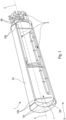
- the tank 1, making it possible to illustrate the invention and represented schematically in a particular embodiment on the Figure 1 is a tank for liquid hydrogen.
- the tank 1, with longitudinal axis XX comprises two tanks 2A and 2B, namely an external tank 2A and an internal tank 2B which is arranged in the external tank 2A.
- the tank 1 may also comprise a set of usual systems S. These systems S are arranged at least partly inside the internal tank 2B and comprise pipes, sensors, a cooling finger, ..., and in particular all the usual elements necessary to generate the low temperatures required for the storage of liquid hydrogen.
- a liquid hydrogen tank such as the tank 1 is particularly well suited to equipping a mobile machine operating, at least partially, on hydrogen.
- the tank 1 is intended to equip an aircraft, in particular a transport aircraft.
- a tank 2 of the reservoir 1 is described.
- This tank 2 can correspond to the internal tank 2A or to the external tank 2B.
- the tank 2 comprises a central section 3 of cylindrical shape, representing a shell, of longitudinal axis XX, which is provided with at least one end 4 called free.
- the tank may comprise a central section having shapes other than a cylindrical shape, for example a conical shape.
- the shape of the tank may, in particular, be adapted to the space available for the arrangement of the liquid hydrogen tank, in particular when the latter is intended to equip a mobile machine, for example an aircraft.
- the tank 2 comprises a dome 5 capable of being mounted on the free end 4 of the central section 3 via a so-called open end 6.
- the dome 5 is a hollow element having an envelope open at one longitudinal end, namely a so-called open end 6, and blind at the other longitudinal end (not shown).
- the dome 5 is closed at its blind end by a domed bottom.
- the central section 3 and the dome 5 are capable and intended to be assembled together to form the tank 2, the open end 6 of said dome 5 being arranged on the free end 4 of the central section 3.
- the two free ends 4 of the central section 3 are each provided with a dome 5.
- the free end 4 of the central section 3 comprises a connecting element 7 and the open end 6 of the dome 5 comprises a connecting element 9.
- the connecting elements 7 and 9 are configured to form, when the dome 5 is arranged on the central section 3, a projecting tab 10A, 10B, 10C located outside the tank 2.
- the projecting tab 10A, 10B, 10C is capable of being welded to a so-called projecting end 8 which corresponds to the free end of said projecting tab 10A, 10B, 10C.
- the welding of the projecting tab 10A, 10B, 10C, specified below, represents the fixing link between the connecting elements 7 and 9, and more generally the fixing link between the central section 3 and the dome 5.
- the welding of the projecting tab 10A, 10B, 10C is the only fixing link making it possible to keep the central section 3 and the dome 5 assembled together.
- the central section 3 and the dome 5 may have additional fixing systems, said systems being complementary to said welding.
- the tank 2 (namely in particular the central body 3 and the dome 5) can be made of different materials.
- it can be made of steel, composite material or aluminum.
- the tank 2 is made of aluminum which has the advantage of being a light, strong and inexpensive material.
- the mechanical characteristics of aluminum are not degraded at very low temperatures.
- the protruding tab 10A, 10B, 10C can be produced in different ways.
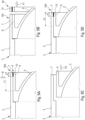
- the connecting element 7 corresponds to an extension 12 of the central section 3.
- This extension 12 corresponds to the extension of the structure of the central section 3 along the longitudinal axis XX, at the free end 4.
- the central section 3 being cylindrical
- the extension 12 corresponds to a ring at the free end 4, having a cylindrical internal face 19.
- the connecting element 9 corresponds to a longitudinal collar 11, of cylindrical shape, arranged on the external face 27 of the wall of the dome 5, at the open end 6.
- the longitudinal collar 11 has a symmetry of revolution, of axis XX, and corresponds to a tubular section extending from the open end 6 of the dome 5 towards the blind end (open end 6). opposite).
- the longitudinal collar 11 has, at the open end 6, a radial face 22 orthogonal to the longitudinal axis XX.
- the extension 12 and the longitudinal collar 11 have cooperating shapes.
- cooperating shapes are understood to mean different types of identical shapes, as specified below, allowing contact between two faces of the elements considered.
- the diameter of the face 19 of the longitudinal collar 11 is slightly smaller than the diameter of the face 20 (outward) of the extension 12 (cylindrical).
- the longitudinal collar 11 is able to be inserted into the extension 12 with peripheral contact between the faces 19 and 20.
- the longitudinal collar 11 is inserted into the extension 12, these two elements form the projecting tab 10A.
- the projecting tab 10A thus corresponds to a tubular extension (cylindrical), which can be welded to the projecting end 8 as specified below.
- the central section 3 comprises, on its internal face 19, a shoulder 18.
- the lateral face 22 of the open end 6 of the dome 5 is configured to come into contact with a lateral face 21 of said shoulder 18 when the central section 3 and the dome 5 are assembled.
- the shoulder 18 makes it possible to provide a bearing face (namely the lateral face 21) for the dome 5, which makes it easier to assemble and maintain the dome 5 in position on the central section 3.
- the connecting element 7 corresponds to a collar 14, 16 arranged on an external face 28 of the central section 3
- the connecting element 9 corresponds to a collar 15, 17 arranged on the external face 27 of the dome 5.
- the collar 14, 16 and the collar 15, 17 have cooperating shapes so that a face 23, 25 of the collar 14, 16 is able to come into contact with an associated face 24, 26 of the collar 15, 17.
- the collar 14 and the collar 15 correspond to rectilinear collars, extending radially relative to the axis XX towards the outside of the tank 2.
- the face 23 of the collar 14 and the face 24 of the collar 15 are configured to come into contact with each other.
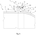
- the dome 5 has at its open end 6 a cylindrical extension 31 extending longitudinally towards the outside of said dome 5 along the axis X-X.
- the connecting element 7 of the central section 3 has at its free end 4 a cylindrical internal face 32 and the cylindrical extension 31 has a cylindrical external face 30.
- the cylindrical extension 31 and the connecting element 7 have cooperating shapes so that said cylindrical extension 31 can be inserted into the central section 3 with peripheral contact between the faces 30 and 32.
- the cylindrical extension 31 makes it easier to position and maintain the dome 5 on the central section 3 when they are assembled together.
- the central section 3 has, at its free end 4, a truncation 33 at the angle formed by the faces 32 and 23.
- This truncation 33 may correspond, for example, to a chamfer made in the usual manner, and makes it easier to insert the dome 5 into the central section 3.
- the central section 3 has, at its free end 4, a thickened wall segment 29, located at the level of the longitudinal part of said central section 3 at the base of the collar 14.
- This wall segment 29 corresponds to a longitudinal cylindrical part of the central section 3 having a greater thickness than the rest of said central section 3.
- the wall segment 29 has the particular objective of stiffening the central section 3 at the base of the collar 14.
- the projecting tongue may be rectilinear, but instead of extending radially relative to the longitudinal axis X-X, therefore orthogonally to the longitudinal axis X-X, it may extend in a direction having an angle other than 90° relative to this longitudinal axis X-X.
- the projecting tab 10C formed by the collar 16 and the collar 17, has a bent shape.
- the collars 16 and 17 have both have an angled shape, these shapes being cooperating so that the face 25 of the collar 16 and the face 26 of the collar 17 are able to come into contact with each other.
- the collars 16 and 17 thus assembled form said projecting tongue 10C.
- the bend formed by the projecting tab 10C has an angle substantially equal to 90°.
- a first segment of the projecting tab 10C is perpendicular to the longitudinal axis XX of the tank 2 and a second segment of the projecting tab 10C is parallel to said longitudinal axis XX.
- the collar 17 has a truncation 34 at the angle formed by the two segments of the elbow.
- This truncation 34 is located on the outer part of said elbow and may in particular correspond to a chamfer made in the usual manner.
- the truncation 34 makes it easier to insert the collar 17 into the collar 16 when the outer faces of the elbow formed by the collar 17 are placed in abutment on the inner faces of the elbow formed by the collar 16.
- the projecting tab may have an angled shape comprising an elbow having an angle other than 90°.
- the connecting elements 7 and 9 can be made in different ways. Preferably, they are made of the same material as the central section 3 and the dome 5.
- the connecting element 7 is directly part of the part forming the central body 3 and is therefore integrated into the central body 3.
- the connecting element 9 is directly part of the part forming the dome 5 and is therefore integrated into the dome 5.
- these connecting elements 7 and 9 are individual added parts.
- the connecting elements 7 and 9 are fixed, preferably welded, respectively, on the central section 3 and on the dome 5.
- one of the connecting elements 7 and 9 is an integrated element and the other an attached element.
- the connecting elements 7 and 9 are welded together at the protruding end 8 so as to form the weld of the protruding tab 10A, 10B, 10C.
- This welding is carried out using a welding bead 13 represented schematically by a thick line on the figures 2 to 4 .
- This weld bead 13 is formed at the projecting end 8 of the projecting tab 10A, 10B, 10C, at the interface (i.e. the respective faces in contact) between the connecting elements 7 and 9 and represents the part originating from the fusion of the welded parts (or of a filler metal).
- the depth P of the weld bead 13 means the maximum distance of the fused part extending towards the inside of the material in the direction perpendicular to the interface.
- the welding of the protruding tab 10A, 10B, 10C can be carried out by conventional welding processes, such as MIG/MAG type welding (for “Metal Inert Gas” and “Metal Active Gas” in English), TIG type welding (for “Tungsten Inert Gas” in English), or FSW type friction stir welding (for “Friction Stir Welding” in English).
- MIG/MAG type welding for “Metal Inert Gas” and “Metal Active Gas” in English
- TIG type welding for “Tungsten Inert Gas” in English
- FSW type friction stir welding for “Friction Stir Welding” in English.
- this welding is carried out by friction stir welding which is a process particularly suited to aluminum, aluminum being a material that is difficult to weld.
- the projecting tab 10A, 10B, 10C has a length L which is greater than or equal to twice the depth P (maximum) of the weld bead 13.
- the protruding tab 10A, 10B, 10C has a length L sufficiently large to allow several reopenings of the tank 2.
- the central section 3 and the dome 5 can be disassembled, and the tank 2 opened, which allows access to the interior of said tank 2.
- the cutting of the projecting tab 10A, 10B, 10C is carried out entirely outside the tank 2, which avoids polluting the interior of the tank 2, in particular with shavings emitted during said cutting.
- the tank 2 can then be reassembled. Indeed, to open the tank 2, it is sufficient to cut the end of the projecting tab 10A, 10B, 10C over a length substantially equal to the depth P of the weld bead 13.
- the projecting tab 10A, 10B, 10C has a length at least twice greater than the depth P. Consequently, after opening the tank 2, there remains sufficient length for the projecting tab 10A, 10B, 10C to be welded again by means of a weld bead 13.
- the projecting tab 10A, 10B, 10C has a length L less than or equal to ten times the depth P of the weld bead 13, so as not to be (unnecessarily) too long and not to increase the bulk outside the tank 2.
- the projecting tab 10 has a total length L of between three and five times the depth P (maximum) of the weld bead 13. This multiple corresponds to an estimated average number of openings required of the tank 2 during its lifetime and makes it possible to have a projecting tab 10A, 10B, 10C of limited size.
- the tank 2 can be opened several times during its life and in a clean manner, without damaging the interior of the tank 2.
- the total length of the tank is not reduced after each opening of said tank 2 since the cut is made not on the body of the tank itself but on the projecting tab 10A, 10B, 10C. This allows in particular access to the systems S located inside the tank 2, for example to carry out maintenance or troubleshooting operations.
- the tank 2 comprises two domes 5A, 5B, each of which is fixed, in the manner described above, to one of the two free ends of the central section, as shown in the Figure 1 .
- the tank 2 can be closed at its two free ends, which can make it possible to obtain a tank 2 having a closed, completely hermetic envelope.
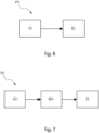
- a method of manufacturing the tank 2 is described below. In the following, this manufacturing method is described for a preferred application, namely for a tank 2 comprising two domes 5A and 5B. However, this method can be applied in a similar manner to a tank 2 comprising a single dome 5.
- the manufacturing step E1 consists of positioning the open ends 6 of the two domes 5 on the free ends 4 of the central section 3 so that the connecting elements 7 and 9 form a projecting tab 10A, 10B, 10C, at each of the two ends of the tank 2.
- it consists of holding the central section 3 and the two domes 5 in position from outside the tank 2, using suitable tools making it possible to keep the assembly stable in order to be able to weld the two projecting tabs 10A, 10B, 10C.
- the welding step E2 consists of welding the connecting elements 7 and 9 (forming the projecting tabs 10A, 10B, 10C) together, at the projecting ends 8, so as to form, each time, a weld bead 13.
- This weld bead 13 corresponds, as indicated above, to the only fixing link between the connecting elements 7 and 9 and to the only fixing link of the corresponding dome 5 on the central section 3.
- the tank 2 is opened at least at one of its ends, then reassembled once these operations are completed.
- a maintenance process for tank 2 is described below, enabling such maintenance or troubleshooting operations to be carried out.
- the cutting step E3 consists of cutting at least the welded protruding end 8 of the protruding tab 10A which has a length L1, using a usual cutting tool, as illustrated by an arrow E on the Figure 5A Such a cutout makes it possible to separate a part 30 (end of the projecting tab 10A, provided with the weld bead 13) from the rest of the projecting tab 10A.
- Removal step E4 consists of removing the dome 5 (which is no longer fixed there) from the central body 3, as illustrated by an arrow F2 on the Figure 5C .
- the tank 2 can be reassembled by welding the dome 5 again to the central section 3.
- the reassembly step E5 consists of putting the dome 5 back into position on the central section 3 so as to reform the projecting tab 10A, 10B, 10C.
- This projecting tab 10A, 10B, 10C thus reformed has a reduced length L2 corresponding to its initial length L1 minus the length of said part 30.
- the length L2 is substantially equal to the length L1, less a distance slightly greater than the depth P.
- the part 30 in fact has a length slightly greater than the depth P of the weld bead 13.
- the reassembly step E5 then consists of welding the dome 5 and the central section 3 together at the level of the projecting end 8 of said projecting tab 10A, 10B, 10C by producing the weld bead 13, as illustrated in the Figure 5D .
- This weld bead 13 has in particular a depth P less than the length L2 of the projecting tab 10A, 10B, 10C. This will allow, if necessary and if the length L2 is sufficient, to implement the process P2 again later.
- the tank 2 thus reassembled can again be used, in the usual way, within the framework of the application considered.
- a tank 2 is provided with a part intended to be welded, namely the projecting tab 10A, 10B, 10C, which is located outside said tank 2. Consequently, the projecting tab 10A, 10B, 10C is accessible from outside the tank 2, which makes it possible to manufacture the tank 2 without having to act inside it.
- the projecting tab 10A, 10B, 10C has surfaces suitable for being used for holding the central section 3 and the dome 5 in position when they are assembled.
- the projecting end 8 of the projecting tab 10A, 10B, 10C is easily accessible, which makes it possible to easily implement a welding process.
- the tools can be removed without constraint since they are exclusively positioned outside the tank 2.
- the projecting tab 10A, 10B, 10C has a length L such that it is possible to open the tank 2 by acting solely on said projecting tab 10A, 10B, 10C. Indeed, by cutting the welded projecting end 8, it is possible to easily separate the central section 3 and the dome 5. The tank 2 can therefore be opened without risking polluting the interior with, for example, cutting chips.
- the protruding tab 10A, 10B, 10C is not cut out entirely during an opening, it is possible to weld the central section 3 and the dome 5 together again, using the remaining length of the protruding tab 10A, 10B, 10C.
- the tank 2 can therefore be opened and then reassembled several times, and this by reducing the length of the protruding tab 10A, 10B, 10C and not the total length of said tank 2.
- the tank 2 as described above, is intended to be integrated into a tank 1 for liquid hydrogen.
- the tank 1 comprises two tanks 2 of this type, corresponding respectively to the external tank (identified by the reference 2A) and the internal tank (identified by the reference 2B).
- the inner tank 2B is arranged inside the outer tank 2A.
- the outer tank 2A can in particular serve as a protective and insulating enclosure, while the inner tank 2B can in particular serve as a container for liquid hydrogen.
- the tank 1 also comprises the set of systems S.
Landscapes
- Engineering & Computer Science (AREA)
- Mechanical Engineering (AREA)
- General Engineering & Computer Science (AREA)
- Physics & Mathematics (AREA)
- Thermal Sciences (AREA)
- Filling Or Discharging Of Gas Storage Vessels (AREA)
Claims (2)
- Verfahren zur Wartung eines Behälters, insbesondere für einen Flüssigwasserstofftank, wobei der Behälter (2) mindestens einen Mittelabschnitt (3), der mit mindestens einem sogenannten freien Ende (4) versehen ist, und mindestens eine Kuppel (5) aufweist, die mit einem sogenannten offenen Ende (6) versehen ist, das auf dem freien Ende (4) des Mittelabschnitts (3) angeordnet ist, wobei das freie Ende (4) des Mittelabschnitts (3) ein erstes Verbindungselement (7) umfasst, wobei das offene Ende (6) der Kuppel (5) an einer Außenseite (26) der Kuppel (5) ein zweites Verbindungselement (9) umfasst, und wobei das erste Verbindungselement (7) und das zweite Verbindungselement (9) dazu konfiguriert sind, eine vorspringende Zunge (10A, 10B, 10C) zu bilden, die sich von dem Behälter (2) nach außen erstreckt und mit einem vorspringenden Ende (8) durch eine Schweißnaht (13) verschweißt ist,
dadurch gekennzeichnet, dass es mindestens die folgenden Schritte umfasst:- einen Schritt des Schneidens (E3), bestehend aus dem Schneiden eines Teils (30) der vorspringenden Zunge (10A, 10B, 10C), die eine anfängliche Länge (L1) aufweist, wobei der geschnittene Teil (30) mindestens dem geschweißten vorspringenden Ende (8) der vorspringenden Zunge (10A, 10B, 10C) entspricht, das die Schweißnaht (13) aufweist, und der geschnittene Teil (30) eine Länge aufweist, die größer als eine Tiefe (P) der Schweißnaht (13) ist; und- einen Schritt des Auftragens (E4), bestehend aus dem Öffnen des Behälters (2), der mindestens die Kuppel (5) und den Mittelabschnitt (3) umfasst, wobei mindestens die Kuppel (5) von dem Mittelabschnitt (3) getrennt wird, die nicht mehr aneinander befestigt sind, wodurch ein Zugang zum Behälter (2) ermöglicht wird, um Wartungsvorgänge auszuführen. - Verfahren nach Anspruch 1,
dadurch gekennzeichnet, dass es weiter einen Schritt der Remontage (E5) umfasst, bestehend aus dem Wiedereinsetzen der Kuppel (5) auf dem Mittelabschnitt (3), um die vorspringende Zunge (10A, 10B, 10C) neu zu formen, wobei die vorspringende Zunge (10A, 10B, 10C) eine verringerte Länge (L2) aufweist, die ihrer ursprünglichen Länge (L1) abzüglich der Länge des ausgeschnittenen Teils (30) entspricht, und die Kuppel (5) und den Mittelabschnitt (3) im Bereich des vorspringenden Endes (8) der vorspringenden Zunge (10A, 10B, 10C) miteinander zu verschweißen, indem eine Schweißnaht (13) ausgeführt wird, die eine Tiefe (P) aufweist, die geringer ist als die verringerte Länge (L2) der vorspringenden Zunge (10A, 10B, 10C).
Applications Claiming Priority (1)
| Application Number | Priority Date | Filing Date | Title |
|---|---|---|---|
| FR2108275A FR3125856A1 (fr) | 2021-07-29 | 2021-07-29 | Cuve, en particulier pour un réservoir à hydrogène liquide, pourvue d’au moins un dôme fixé par une soudure externe. |
Publications (2)
| Publication Number | Publication Date |
|---|---|
| EP4124791A1 EP4124791A1 (de) | 2023-02-01 |
| EP4124791B1 true EP4124791B1 (de) | 2025-03-26 |
Family
ID=77999136
Family Applications (1)
| Application Number | Title | Priority Date | Filing Date |
|---|---|---|---|
| EP22184491.3A Active EP4124791B1 (de) | 2021-07-29 | 2022-07-12 | Behälter, insbesondere für einen flüssigwasserstofftank, der mit mindestens einer kuppel versehen ist, die durch eine äussere schweissnaht befestigt ist |
Country Status (4)
| Country | Link |
|---|---|
| US (2) | US20230036707A1 (de) |
| EP (1) | EP4124791B1 (de) |
| CN (1) | CN115681786A (de) |
| FR (1) | FR3125856A1 (de) |
Families Citing this family (1)
| Publication number | Priority date | Publication date | Assignee | Title |
|---|---|---|---|---|
| FR3149946A1 (fr) * | 2023-06-13 | 2024-12-20 | Airbus Operations (S.A.S.) | Cuve de réservoir comprenant une virole et au moins une paroi d’extrémité assemblées de manière à limiter les déformations de ladite paroi d’extrémité |
Family Cites Families (10)
| Publication number | Priority date | Publication date | Assignee | Title |
|---|---|---|---|---|
| DE1072636B (de) * | 1953-05-09 | 1960-01-07 | Aktiebolaget B A Hjorth ix Co Stockholm | Geloteter Be halter fur unter Druck stehende Flussig keiten und Gase |
| BE590656A (de) * | 1959-05-28 | |||
| DE9102936U1 (de) * | 1991-03-12 | 1992-07-09 | Cyron, Theodor, 5060 Bergisch Gladbach | Doppelwandiger Druckbehälter |
| JP3872952B2 (ja) * | 2000-10-27 | 2007-01-24 | 東京エレクトロン株式会社 | 熱処理装置及び熱処理方法 |
| US6986270B2 (en) * | 2003-02-28 | 2006-01-17 | Sara Lee Corporation | Knitted fabric construction with improved moisture management |
| JP5083176B2 (ja) * | 2008-11-05 | 2012-11-28 | トヨタ自動車株式会社 | ライナの製造方法及び分割ライナ |
| JP5071351B2 (ja) * | 2008-11-07 | 2012-11-14 | トヨタ自動車株式会社 | 樹脂ライナの製造方法および流体貯留容器の製造方法 |
| AT508042A2 (de) * | 2009-03-24 | 2010-10-15 | Alutech Gmbh | Betriebsmitteleinheit mit einem temperaturempfindlichen fahrzeugbetriebsmittel |
| AT508358B1 (de) * | 2009-12-15 | 2011-01-15 | Alutech Gmbh | Verfahren zum herstellen eines behälters für ein temperaturempfindliches betriebsmittel und behälter hiefür |
| JP6783277B2 (ja) * | 2018-09-14 | 2020-11-11 | 本田技研工業株式会社 | ライナ構成部材、高圧タンク及びその製造方法 |
-
2021
- 2021-07-29 FR FR2108275A patent/FR3125856A1/fr not_active Ceased
-
2022
- 2022-07-12 EP EP22184491.3A patent/EP4124791B1/de active Active
- 2022-07-25 US US17/872,334 patent/US20230036707A1/en not_active Abandoned
- 2022-07-29 CN CN202210909064.8A patent/CN115681786A/zh active Pending
-
2024
- 2024-08-13 US US18/802,811 patent/US20240401742A1/en active Pending
Also Published As
| Publication number | Publication date |
|---|---|
| CN115681786A (zh) | 2023-02-03 |
| US20230036707A1 (en) | 2023-02-02 |
| US20240401742A1 (en) | 2024-12-05 |
| FR3125856A1 (fr) | 2023-02-03 |
| EP4124791A1 (de) | 2023-02-01 |
Similar Documents
| Publication | Publication Date | Title |
|---|---|---|
| EP2212612B1 (de) | Druckflüssigkeitstank und verfahren zur herstellung eines solchen tanks | |
| EP2808595B1 (de) | Behälter und sein Herstellungsverfahren | |
| EP4124791B1 (de) | Behälter, insbesondere für einen flüssigwasserstofftank, der mit mindestens einer kuppel versehen ist, die durch eine äussere schweissnaht befestigt ist | |
| EP1221728B1 (de) | Wiederverschliessbares Ventil und dieses Ventil enthaltender elektrochemischer Generator | |
| EP2320429B1 (de) | Verpackung für den Transport und/oder zur Zwischenlagerung radioaktiver Stoffe, die radial geschichtete Strahlenschutzelemente umfasst | |
| EP2893227B1 (de) | Bürstenartige kreisförmige dichtung | |
| WO2021013605A1 (fr) | Coupelle de valve pour récipient sous pression | |
| EP3469206B1 (de) | Raketentriebwerkbrennkammer mit rippen mit variabler zusammensetzung | |
| BE1027458B1 (fr) | Coupelle de valve pour récipient sous pression | |
| EP3023732B1 (de) | Pyrotechnische trennvorrichtung, die zwei unabhängige strukturelemente umfasst, die zusammengebaut sind, und entsprechendes herstellungsverfahren | |
| EP4004420B1 (de) | Steckelement für eine fluidische kupplung, fluidische kupplung mit einem solchen steckelement und verfahren zum zusammenbau eines solchen steckelements | |
| EP2320432B1 (de) | Verpackung für den Transport und/oder zur Zwischenlagerung radioaktiver Stoffe, die eine verstärkte Wärmeübertragung ermöglicht | |
| WO2009024684A1 (fr) | Procédé de fabrication d' un élément de génie chimique | |
| EP0642875B1 (de) | Verfahren und Vorrichtung zum Herstellen von Flüssiggasflaschen, und hergestellte Flaschen | |
| FR3061046A1 (fr) | Dispositif de pliage pour former une ondulation dans une tole metallique et procede d'utilisation dudit dispositif | |
| FR3104044A1 (fr) | Molette de soudage à bague amovible. | |
| FR3042635A1 (fr) | Element de refroidissement avec embase pour evacuer de la chaleur d'un emballage | |
| EP4124792A1 (de) | Behälter, insbesondere für einen flüssigwasserstofftank, der mit innenschienen zum einbau eines gerätemoduls versehen ist | |
| EP3743928B1 (de) | Lagerkorb für radioaktive materialien mit optimiertem platzbedarf und mit gehäusen mit genauerer geometrie | |
| WO2021058887A1 (fr) | Panier de rangement pour matières radioactives, à conception simplifiée conférant des propriétés améliorées de transfert thermique | |
| FR2492050A1 (fr) | Procede de fabrication de reservoirs pour fluides sous pression | |
| FR3129861A1 (fr) | Réservoir comprenant au moins deux parties reliées par une couronne de jonction et des soudures obtenues par un procédé de soudage par friction et procédé de fabrication dudit réservoir | |
| BE458777A (de) |
Legal Events
| Date | Code | Title | Description |
|---|---|---|---|
| PUAI | Public reference made under article 153(3) epc to a published international application that has entered the european phase |
Free format text: ORIGINAL CODE: 0009012 |
|
| STAA | Information on the status of an ep patent application or granted ep patent |
Free format text: STATUS: THE APPLICATION HAS BEEN PUBLISHED |
|
| AK | Designated contracting states |
Kind code of ref document: A1 Designated state(s): AL AT BE BG CH CY CZ DE DK EE ES FI FR GB GR HR HU IE IS IT LI LT LU LV MC MK MT NL NO PL PT RO RS SE SI SK SM TR |
|
| STAA | Information on the status of an ep patent application or granted ep patent |
Free format text: STATUS: REQUEST FOR EXAMINATION WAS MADE |
|
| 17P | Request for examination filed |
Effective date: 20230713 |
|
| RBV | Designated contracting states (corrected) |
Designated state(s): AL AT BE BG CH CY CZ DE DK EE ES FI FR GB GR HR HU IE IS IT LI LT LU LV MC MK MT NL NO PL PT RO RS SE SI SK SM TR |
|
| GRAP | Despatch of communication of intention to grant a patent |
Free format text: ORIGINAL CODE: EPIDOSNIGR1 |
|
| STAA | Information on the status of an ep patent application or granted ep patent |
Free format text: STATUS: GRANT OF PATENT IS INTENDED |
|
| INTG | Intention to grant announced |
Effective date: 20241022 |
|
| RAP3 | Party data changed (applicant data changed or rights of an application transferred) |
Owner name: AIRBUS OPERATIONS (SAS) |
|
| RIC1 | Information provided on ipc code assigned before grant |
Ipc: F17C 3/10 20060101AFI20241011BHEP |
|
| RIN1 | Information on inventor provided before grant (corrected) |
Inventor name: GUILLOTEAU, DAMIEN |
|
| GRAS | Grant fee paid |
Free format text: ORIGINAL CODE: EPIDOSNIGR3 |
|
| GRAA | (expected) grant |
Free format text: ORIGINAL CODE: 0009210 |
|
| STAA | Information on the status of an ep patent application or granted ep patent |
Free format text: STATUS: THE PATENT HAS BEEN GRANTED |
|
| AK | Designated contracting states |
Kind code of ref document: B1 Designated state(s): AL AT BE BG CH CY CZ DE DK EE ES FI FR GB GR HR HU IE IS IT LI LT LU LV MC MK MT NL NO PL PT RO RS SE SI SK SM TR |
|
| REG | Reference to a national code |
Ref country code: GB Ref legal event code: FG4D Free format text: NOT ENGLISH |
|
| REG | Reference to a national code |
Ref country code: CH Ref legal event code: EP |
|
| REG | Reference to a national code |
Ref country code: DE Ref legal event code: R096 Ref document number: 602022012167 Country of ref document: DE |
|
| REG | Reference to a national code |
Ref country code: IE Ref legal event code: FG4D Free format text: LANGUAGE OF EP DOCUMENT: FRENCH |
|
| PG25 | Lapsed in a contracting state [announced via postgrant information from national office to epo] |
Ref country code: RS Free format text: LAPSE BECAUSE OF FAILURE TO SUBMIT A TRANSLATION OF THE DESCRIPTION OR TO PAY THE FEE WITHIN THE PRESCRIBED TIME-LIMIT Effective date: 20250626 |
|
| PG25 | Lapsed in a contracting state [announced via postgrant information from national office to epo] |
Ref country code: FI Free format text: LAPSE BECAUSE OF FAILURE TO SUBMIT A TRANSLATION OF THE DESCRIPTION OR TO PAY THE FEE WITHIN THE PRESCRIBED TIME-LIMIT Effective date: 20250326 |
|
| REG | Reference to a national code |
Ref country code: LT Ref legal event code: MG9D |
|
| PG25 | Lapsed in a contracting state [announced via postgrant information from national office to epo] |
Ref country code: NO Free format text: LAPSE BECAUSE OF FAILURE TO SUBMIT A TRANSLATION OF THE DESCRIPTION OR TO PAY THE FEE WITHIN THE PRESCRIBED TIME-LIMIT Effective date: 20250626 |
|
| PG25 | Lapsed in a contracting state [announced via postgrant information from national office to epo] |
Ref country code: HR Free format text: LAPSE BECAUSE OF FAILURE TO SUBMIT A TRANSLATION OF THE DESCRIPTION OR TO PAY THE FEE WITHIN THE PRESCRIBED TIME-LIMIT Effective date: 20250326 |
|
| PG25 | Lapsed in a contracting state [announced via postgrant information from national office to epo] |
Ref country code: LV Free format text: LAPSE BECAUSE OF FAILURE TO SUBMIT A TRANSLATION OF THE DESCRIPTION OR TO PAY THE FEE WITHIN THE PRESCRIBED TIME-LIMIT Effective date: 20250326 |
|
| PG25 | Lapsed in a contracting state [announced via postgrant information from national office to epo] |
Ref country code: GR Free format text: LAPSE BECAUSE OF FAILURE TO SUBMIT A TRANSLATION OF THE DESCRIPTION OR TO PAY THE FEE WITHIN THE PRESCRIBED TIME-LIMIT Effective date: 20250627 Ref country code: BG Free format text: LAPSE BECAUSE OF FAILURE TO SUBMIT A TRANSLATION OF THE DESCRIPTION OR TO PAY THE FEE WITHIN THE PRESCRIBED TIME-LIMIT Effective date: 20250326 |
|
| REG | Reference to a national code |
Ref country code: NL Ref legal event code: MP Effective date: 20250326 |
|
| PG25 | Lapsed in a contracting state [announced via postgrant information from national office to epo] |
Ref country code: NL Free format text: LAPSE BECAUSE OF FAILURE TO SUBMIT A TRANSLATION OF THE DESCRIPTION OR TO PAY THE FEE WITHIN THE PRESCRIBED TIME-LIMIT Effective date: 20250326 |
|
| PG25 | Lapsed in a contracting state [announced via postgrant information from national office to epo] |
Ref country code: SE Free format text: LAPSE BECAUSE OF FAILURE TO SUBMIT A TRANSLATION OF THE DESCRIPTION OR TO PAY THE FEE WITHIN THE PRESCRIBED TIME-LIMIT Effective date: 20250326 |
|
| REG | Reference to a national code |
Ref country code: AT Ref legal event code: MK05 Ref document number: 1779280 Country of ref document: AT Kind code of ref document: T Effective date: 20250326 |
|
| PG25 | Lapsed in a contracting state [announced via postgrant information from national office to epo] |
Ref country code: SM Free format text: LAPSE BECAUSE OF FAILURE TO SUBMIT A TRANSLATION OF THE DESCRIPTION OR TO PAY THE FEE WITHIN THE PRESCRIBED TIME-LIMIT Effective date: 20250326 |
|
| PG25 | Lapsed in a contracting state [announced via postgrant information from national office to epo] |
Ref country code: ES Free format text: LAPSE BECAUSE OF FAILURE TO SUBMIT A TRANSLATION OF THE DESCRIPTION OR TO PAY THE FEE WITHIN THE PRESCRIBED TIME-LIMIT Effective date: 20250326 Ref country code: PT Free format text: LAPSE BECAUSE OF FAILURE TO SUBMIT A TRANSLATION OF THE DESCRIPTION OR TO PAY THE FEE WITHIN THE PRESCRIBED TIME-LIMIT Effective date: 20250728 |
|
| PGFP | Annual fee paid to national office [announced via postgrant information from national office to epo] |
Ref country code: DE Payment date: 20250722 Year of fee payment: 4 |
|
| PG25 | Lapsed in a contracting state [announced via postgrant information from national office to epo] |
Ref country code: PL Free format text: LAPSE BECAUSE OF FAILURE TO SUBMIT A TRANSLATION OF THE DESCRIPTION OR TO PAY THE FEE WITHIN THE PRESCRIBED TIME-LIMIT Effective date: 20250326 Ref country code: IT Free format text: LAPSE BECAUSE OF FAILURE TO SUBMIT A TRANSLATION OF THE DESCRIPTION OR TO PAY THE FEE WITHIN THE PRESCRIBED TIME-LIMIT Effective date: 20250326 |
|
| PG25 | Lapsed in a contracting state [announced via postgrant information from national office to epo] |
Ref country code: AT Free format text: LAPSE BECAUSE OF FAILURE TO SUBMIT A TRANSLATION OF THE DESCRIPTION OR TO PAY THE FEE WITHIN THE PRESCRIBED TIME-LIMIT Effective date: 20250326 |
|
| PGFP | Annual fee paid to national office [announced via postgrant information from national office to epo] |
Ref country code: FR Payment date: 20250725 Year of fee payment: 4 |
|
| PG25 | Lapsed in a contracting state [announced via postgrant information from national office to epo] |
Ref country code: EE Free format text: LAPSE BECAUSE OF FAILURE TO SUBMIT A TRANSLATION OF THE DESCRIPTION OR TO PAY THE FEE WITHIN THE PRESCRIBED TIME-LIMIT Effective date: 20250326 |
|
| PG25 | Lapsed in a contracting state [announced via postgrant information from national office to epo] |
Ref country code: RO Free format text: LAPSE BECAUSE OF FAILURE TO SUBMIT A TRANSLATION OF THE DESCRIPTION OR TO PAY THE FEE WITHIN THE PRESCRIBED TIME-LIMIT Effective date: 20250326 |
|
| PG25 | Lapsed in a contracting state [announced via postgrant information from national office to epo] |
Ref country code: SK Free format text: LAPSE BECAUSE OF FAILURE TO SUBMIT A TRANSLATION OF THE DESCRIPTION OR TO PAY THE FEE WITHIN THE PRESCRIBED TIME-LIMIT Effective date: 20250326 |
|
| PG25 | Lapsed in a contracting state [announced via postgrant information from national office to epo] |
Ref country code: IS Free format text: LAPSE BECAUSE OF FAILURE TO SUBMIT A TRANSLATION OF THE DESCRIPTION OR TO PAY THE FEE WITHIN THE PRESCRIBED TIME-LIMIT Effective date: 20250726 |
|
| REG | Reference to a national code |
Ref country code: DE Ref legal event code: R097 Ref document number: 602022012167 Country of ref document: DE |
|
| PG25 | Lapsed in a contracting state [announced via postgrant information from national office to epo] |
Ref country code: DK Free format text: LAPSE BECAUSE OF FAILURE TO SUBMIT A TRANSLATION OF THE DESCRIPTION OR TO PAY THE FEE WITHIN THE PRESCRIBED TIME-LIMIT Effective date: 20250326 |
|
| PG25 | Lapsed in a contracting state [announced via postgrant information from national office to epo] |
Ref country code: CZ Free format text: LAPSE BECAUSE OF FAILURE TO SUBMIT A TRANSLATION OF THE DESCRIPTION OR TO PAY THE FEE WITHIN THE PRESCRIBED TIME-LIMIT Effective date: 20250326 |
|
| PLBE | No opposition filed within time limit |
Free format text: ORIGINAL CODE: 0009261 |
|
| STAA | Information on the status of an ep patent application or granted ep patent |
Free format text: STATUS: NO OPPOSITION FILED WITHIN TIME LIMIT |
|
| REG | Reference to a national code |
Ref country code: CH Ref legal event code: L10 Free format text: ST27 STATUS EVENT CODE: U-0-0-L10-L00 (AS PROVIDED BY THE NATIONAL OFFICE) Effective date: 20260211 |
|
| REG | Reference to a national code |
Ref country code: CH Ref legal event code: H13 Free format text: ST27 STATUS EVENT CODE: U-0-0-H10-H13 (AS PROVIDED BY THE NATIONAL OFFICE) Effective date: 20260224 |
|
| 26N | No opposition filed |
Effective date: 20260105 |
|
| PG25 | Lapsed in a contracting state [announced via postgrant information from national office to epo] |
Ref country code: LU Free format text: LAPSE BECAUSE OF NON-PAYMENT OF DUE FEES Effective date: 20250712 |
|
| REG | Reference to a national code |
Ref country code: BE Ref legal event code: MM Effective date: 20250731 |
|
| PG25 | Lapsed in a contracting state [announced via postgrant information from national office to epo] |
Ref country code: BE Free format text: LAPSE BECAUSE OF NON-PAYMENT OF DUE FEES Effective date: 20250731 |