EP4124730B1 - Verfahren zum steuern eines abgasnachbehandlungssystems für ein abgassystem eines verbrennungsmotors - Google Patents
Verfahren zum steuern eines abgasnachbehandlungssystems für ein abgassystem eines verbrennungsmotors Download PDFInfo
- Publication number
- EP4124730B1 EP4124730B1 EP22186641.1A EP22186641A EP4124730B1 EP 4124730 B1 EP4124730 B1 EP 4124730B1 EP 22186641 A EP22186641 A EP 22186641A EP 4124730 B1 EP4124730 B1 EP 4124730B1
- Authority
- EP
- European Patent Office
- Prior art keywords
- combustion engine
- internal combustion
- catalytic converter
- burner
- turned
- Prior art date
- Legal status (The legal status is an assumption and is not a legal conclusion. Google has not performed a legal analysis and makes no representation as to the accuracy of the status listed.)
- Active
Links
Images


Classifications
-
- F—MECHANICAL ENGINEERING; LIGHTING; HEATING; WEAPONS; BLASTING
- F01—MACHINES OR ENGINES IN GENERAL; ENGINE PLANTS IN GENERAL; STEAM ENGINES
- F01N—GAS-FLOW SILENCERS OR EXHAUST APPARATUS FOR MACHINES OR ENGINES IN GENERAL; GAS-FLOW SILENCERS OR EXHAUST APPARATUS FOR INTERNAL-COMBUSTION ENGINES
- F01N3/00—Exhaust or silencing apparatus having means for purifying, rendering innocuous, or otherwise treating exhaust
- F01N3/08—Exhaust or silencing apparatus having means for purifying, rendering innocuous, or otherwise treating exhaust for rendering innocuous
- F01N3/10—Exhaust or silencing apparatus having means for purifying, rendering innocuous, or otherwise treating exhaust for rendering innocuous by thermal or catalytic conversion of noxious components of exhaust
- F01N3/18—Exhaust or silencing apparatus having means for purifying, rendering innocuous, or otherwise treating exhaust for rendering innocuous by thermal or catalytic conversion of noxious components of exhaust characterised by methods of operation; Control
- F01N3/20—Exhaust or silencing apparatus having means for purifying, rendering innocuous, or otherwise treating exhaust for rendering innocuous by thermal or catalytic conversion of noxious components of exhaust characterised by methods of operation; Control specially adapted for catalytic conversion
- F01N3/2006—Periodically heating or cooling catalytic reactors, e.g. at cold starting or overheating
-
- F—MECHANICAL ENGINEERING; LIGHTING; HEATING; WEAPONS; BLASTING
- F01—MACHINES OR ENGINES IN GENERAL; ENGINE PLANTS IN GENERAL; STEAM ENGINES
- F01N—GAS-FLOW SILENCERS OR EXHAUST APPARATUS FOR MACHINES OR ENGINES IN GENERAL; GAS-FLOW SILENCERS OR EXHAUST APPARATUS FOR INTERNAL-COMBUSTION ENGINES
- F01N3/00—Exhaust or silencing apparatus having means for purifying, rendering innocuous, or otherwise treating exhaust
- F01N3/08—Exhaust or silencing apparatus having means for purifying, rendering innocuous, or otherwise treating exhaust for rendering innocuous
- F01N3/10—Exhaust or silencing apparatus having means for purifying, rendering innocuous, or otherwise treating exhaust for rendering innocuous by thermal or catalytic conversion of noxious components of exhaust
- F01N3/18—Exhaust or silencing apparatus having means for purifying, rendering innocuous, or otherwise treating exhaust for rendering innocuous by thermal or catalytic conversion of noxious components of exhaust characterised by methods of operation; Control
- F01N3/20—Exhaust or silencing apparatus having means for purifying, rendering innocuous, or otherwise treating exhaust for rendering innocuous by thermal or catalytic conversion of noxious components of exhaust characterised by methods of operation; Control specially adapted for catalytic conversion
- F01N3/2006—Periodically heating or cooling catalytic reactors, e.g. at cold starting or overheating
- F01N3/2033—Periodically heating or cooling catalytic reactors, e.g. at cold starting or overheating using a fuel burner or introducing fuel into exhaust duct
-
- F—MECHANICAL ENGINEERING; LIGHTING; HEATING; WEAPONS; BLASTING
- F01—MACHINES OR ENGINES IN GENERAL; ENGINE PLANTS IN GENERAL; STEAM ENGINES
- F01N—GAS-FLOW SILENCERS OR EXHAUST APPARATUS FOR MACHINES OR ENGINES IN GENERAL; GAS-FLOW SILENCERS OR EXHAUST APPARATUS FOR INTERNAL-COMBUSTION ENGINES
- F01N3/00—Exhaust or silencing apparatus having means for purifying, rendering innocuous, or otherwise treating exhaust
- F01N3/02—Exhaust or silencing apparatus having means for purifying, rendering innocuous, or otherwise treating exhaust for cooling, or for removing solid constituents of, exhaust
- F01N3/021—Exhaust or silencing apparatus having means for purifying, rendering innocuous, or otherwise treating exhaust for cooling, or for removing solid constituents of, exhaust by means of filters
- F01N3/023—Exhaust or silencing apparatus having means for purifying, rendering innocuous, or otherwise treating exhaust for cooling, or for removing solid constituents of, exhaust by means of filters using means for regenerating the filters, e.g. by burning trapped particles
- F01N3/025—Exhaust or silencing apparatus having means for purifying, rendering innocuous, or otherwise treating exhaust for cooling, or for removing solid constituents of, exhaust by means of filters using means for regenerating the filters, e.g. by burning trapped particles using fuel burner or by adding fuel to exhaust
-
- F—MECHANICAL ENGINEERING; LIGHTING; HEATING; WEAPONS; BLASTING
- F01—MACHINES OR ENGINES IN GENERAL; ENGINE PLANTS IN GENERAL; STEAM ENGINES
- F01N—GAS-FLOW SILENCERS OR EXHAUST APPARATUS FOR MACHINES OR ENGINES IN GENERAL; GAS-FLOW SILENCERS OR EXHAUST APPARATUS FOR INTERNAL-COMBUSTION ENGINES
- F01N3/00—Exhaust or silencing apparatus having means for purifying, rendering innocuous, or otherwise treating exhaust
- F01N3/02—Exhaust or silencing apparatus having means for purifying, rendering innocuous, or otherwise treating exhaust for cooling, or for removing solid constituents of, exhaust
- F01N3/021—Exhaust or silencing apparatus having means for purifying, rendering innocuous, or otherwise treating exhaust for cooling, or for removing solid constituents of, exhaust by means of filters
- F01N3/023—Exhaust or silencing apparatus having means for purifying, rendering innocuous, or otherwise treating exhaust for cooling, or for removing solid constituents of, exhaust by means of filters using means for regenerating the filters, e.g. by burning trapped particles
- F01N3/025—Exhaust or silencing apparatus having means for purifying, rendering innocuous, or otherwise treating exhaust for cooling, or for removing solid constituents of, exhaust by means of filters using means for regenerating the filters, e.g. by burning trapped particles using fuel burner or by adding fuel to exhaust
- F01N3/0253—Exhaust or silencing apparatus having means for purifying, rendering innocuous, or otherwise treating exhaust for cooling, or for removing solid constituents of, exhaust by means of filters using means for regenerating the filters, e.g. by burning trapped particles using fuel burner or by adding fuel to exhaust adding fuel to exhaust gases
-
- F—MECHANICAL ENGINEERING; LIGHTING; HEATING; WEAPONS; BLASTING
- F01—MACHINES OR ENGINES IN GENERAL; ENGINE PLANTS IN GENERAL; STEAM ENGINES
- F01N—GAS-FLOW SILENCERS OR EXHAUST APPARATUS FOR MACHINES OR ENGINES IN GENERAL; GAS-FLOW SILENCERS OR EXHAUST APPARATUS FOR INTERNAL-COMBUSTION ENGINES
- F01N3/00—Exhaust or silencing apparatus having means for purifying, rendering innocuous, or otherwise treating exhaust
- F01N3/02—Exhaust or silencing apparatus having means for purifying, rendering innocuous, or otherwise treating exhaust for cooling, or for removing solid constituents of, exhaust
- F01N3/021—Exhaust or silencing apparatus having means for purifying, rendering innocuous, or otherwise treating exhaust for cooling, or for removing solid constituents of, exhaust by means of filters
- F01N3/023—Exhaust or silencing apparatus having means for purifying, rendering innocuous, or otherwise treating exhaust for cooling, or for removing solid constituents of, exhaust by means of filters using means for regenerating the filters, e.g. by burning trapped particles
- F01N3/025—Exhaust or silencing apparatus having means for purifying, rendering innocuous, or otherwise treating exhaust for cooling, or for removing solid constituents of, exhaust by means of filters using means for regenerating the filters, e.g. by burning trapped particles using fuel burner or by adding fuel to exhaust
- F01N3/0253—Exhaust or silencing apparatus having means for purifying, rendering innocuous, or otherwise treating exhaust for cooling, or for removing solid constituents of, exhaust by means of filters using means for regenerating the filters, e.g. by burning trapped particles using fuel burner or by adding fuel to exhaust adding fuel to exhaust gases
- F01N3/0256—Exhaust or silencing apparatus having means for purifying, rendering innocuous, or otherwise treating exhaust for cooling, or for removing solid constituents of, exhaust by means of filters using means for regenerating the filters, e.g. by burning trapped particles using fuel burner or by adding fuel to exhaust adding fuel to exhaust gases the fuel being ignited by electrical means
-
- F—MECHANICAL ENGINEERING; LIGHTING; HEATING; WEAPONS; BLASTING
- F01—MACHINES OR ENGINES IN GENERAL; ENGINE PLANTS IN GENERAL; STEAM ENGINES
- F01N—GAS-FLOW SILENCERS OR EXHAUST APPARATUS FOR MACHINES OR ENGINES IN GENERAL; GAS-FLOW SILENCERS OR EXHAUST APPARATUS FOR INTERNAL-COMBUSTION ENGINES
- F01N3/00—Exhaust or silencing apparatus having means for purifying, rendering innocuous, or otherwise treating exhaust
- F01N3/08—Exhaust or silencing apparatus having means for purifying, rendering innocuous, or otherwise treating exhaust for rendering innocuous
- F01N3/10—Exhaust or silencing apparatus having means for purifying, rendering innocuous, or otherwise treating exhaust for rendering innocuous by thermal or catalytic conversion of noxious components of exhaust
- F01N3/18—Exhaust or silencing apparatus having means for purifying, rendering innocuous, or otherwise treating exhaust for rendering innocuous by thermal or catalytic conversion of noxious components of exhaust characterised by methods of operation; Control
- F01N3/20—Exhaust or silencing apparatus having means for purifying, rendering innocuous, or otherwise treating exhaust for rendering innocuous by thermal or catalytic conversion of noxious components of exhaust characterised by methods of operation; Control specially adapted for catalytic conversion
- F01N3/2006—Periodically heating or cooling catalytic reactors, e.g. at cold starting or overheating
- F01N3/204—Periodically heating or cooling catalytic reactors, e.g. at cold starting or overheating using an exhaust gas igniter, e.g. a spark or glow plug, without introducing fuel into exhaust duct
-
- F—MECHANICAL ENGINEERING; LIGHTING; HEATING; WEAPONS; BLASTING
- F01—MACHINES OR ENGINES IN GENERAL; ENGINE PLANTS IN GENERAL; STEAM ENGINES
- F01N—GAS-FLOW SILENCERS OR EXHAUST APPARATUS FOR MACHINES OR ENGINES IN GENERAL; GAS-FLOW SILENCERS OR EXHAUST APPARATUS FOR INTERNAL-COMBUSTION ENGINES
- F01N3/00—Exhaust or silencing apparatus having means for purifying, rendering innocuous, or otherwise treating exhaust
- F01N3/08—Exhaust or silencing apparatus having means for purifying, rendering innocuous, or otherwise treating exhaust for rendering innocuous
- F01N3/10—Exhaust or silencing apparatus having means for purifying, rendering innocuous, or otherwise treating exhaust for rendering innocuous by thermal or catalytic conversion of noxious components of exhaust
- F01N3/24—Exhaust or silencing apparatus having means for purifying, rendering innocuous, or otherwise treating exhaust for rendering innocuous by thermal or catalytic conversion of noxious components of exhaust characterised by constructional aspects of converting apparatus
- F01N3/30—Arrangements for supply of additional air
- F01N3/32—Arrangements for supply of additional air using air pump
-
- F—MECHANICAL ENGINEERING; LIGHTING; HEATING; WEAPONS; BLASTING
- F01—MACHINES OR ENGINES IN GENERAL; ENGINE PLANTS IN GENERAL; STEAM ENGINES
- F01N—GAS-FLOW SILENCERS OR EXHAUST APPARATUS FOR MACHINES OR ENGINES IN GENERAL; GAS-FLOW SILENCERS OR EXHAUST APPARATUS FOR INTERNAL-COMBUSTION ENGINES
- F01N3/00—Exhaust or silencing apparatus having means for purifying, rendering innocuous, or otherwise treating exhaust
- F01N3/08—Exhaust or silencing apparatus having means for purifying, rendering innocuous, or otherwise treating exhaust for rendering innocuous
- F01N3/10—Exhaust or silencing apparatus having means for purifying, rendering innocuous, or otherwise treating exhaust for rendering innocuous by thermal or catalytic conversion of noxious components of exhaust
- F01N3/24—Exhaust or silencing apparatus having means for purifying, rendering innocuous, or otherwise treating exhaust for rendering innocuous by thermal or catalytic conversion of noxious components of exhaust characterised by constructional aspects of converting apparatus
- F01N3/36—Arrangements for supply of additional fuel
-
- F—MECHANICAL ENGINEERING; LIGHTING; HEATING; WEAPONS; BLASTING
- F01—MACHINES OR ENGINES IN GENERAL; ENGINE PLANTS IN GENERAL; STEAM ENGINES
- F01N—GAS-FLOW SILENCERS OR EXHAUST APPARATUS FOR MACHINES OR ENGINES IN GENERAL; GAS-FLOW SILENCERS OR EXHAUST APPARATUS FOR INTERNAL-COMBUSTION ENGINES
- F01N3/00—Exhaust or silencing apparatus having means for purifying, rendering innocuous, or otherwise treating exhaust
- F01N3/08—Exhaust or silencing apparatus having means for purifying, rendering innocuous, or otherwise treating exhaust for rendering innocuous
- F01N3/10—Exhaust or silencing apparatus having means for purifying, rendering innocuous, or otherwise treating exhaust for rendering innocuous by thermal or catalytic conversion of noxious components of exhaust
- F01N3/24—Exhaust or silencing apparatus having means for purifying, rendering innocuous, or otherwise treating exhaust for rendering innocuous by thermal or catalytic conversion of noxious components of exhaust characterised by constructional aspects of converting apparatus
- F01N3/38—Arrangements for igniting
-
- F—MECHANICAL ENGINEERING; LIGHTING; HEATING; WEAPONS; BLASTING
- F01—MACHINES OR ENGINES IN GENERAL; ENGINE PLANTS IN GENERAL; STEAM ENGINES
- F01N—GAS-FLOW SILENCERS OR EXHAUST APPARATUS FOR MACHINES OR ENGINES IN GENERAL; GAS-FLOW SILENCERS OR EXHAUST APPARATUS FOR INTERNAL-COMBUSTION ENGINES
- F01N2240/00—Combination or association of two or more different exhaust treating devices, or of at least one such device with an auxiliary device, not covered by indexing codes F01N2230/00 or F01N2250/00, one of the devices being
- F01N2240/14—Combination or association of two or more different exhaust treating devices, or of at least one such device with an auxiliary device, not covered by indexing codes F01N2230/00 or F01N2250/00, one of the devices being a fuel burner
-
- F—MECHANICAL ENGINEERING; LIGHTING; HEATING; WEAPONS; BLASTING
- F01—MACHINES OR ENGINES IN GENERAL; ENGINE PLANTS IN GENERAL; STEAM ENGINES
- F01N—GAS-FLOW SILENCERS OR EXHAUST APPARATUS FOR MACHINES OR ENGINES IN GENERAL; GAS-FLOW SILENCERS OR EXHAUST APPARATUS FOR INTERNAL-COMBUSTION ENGINES
- F01N2550/00—Monitoring or diagnosing the deterioration of exhaust systems
- F01N2550/05—Systems for adding substances into exhaust
-
- F—MECHANICAL ENGINEERING; LIGHTING; HEATING; WEAPONS; BLASTING
- F01—MACHINES OR ENGINES IN GENERAL; ENGINE PLANTS IN GENERAL; STEAM ENGINES
- F01N—GAS-FLOW SILENCERS OR EXHAUST APPARATUS FOR MACHINES OR ENGINES IN GENERAL; GAS-FLOW SILENCERS OR EXHAUST APPARATUS FOR INTERNAL-COMBUSTION ENGINES
- F01N2610/00—Adding substances to exhaust gases
- F01N2610/03—Adding substances to exhaust gases the substance being hydrocarbons, e.g. engine fuel
-
- F—MECHANICAL ENGINEERING; LIGHTING; HEATING; WEAPONS; BLASTING
- F01—MACHINES OR ENGINES IN GENERAL; ENGINE PLANTS IN GENERAL; STEAM ENGINES
- F01N—GAS-FLOW SILENCERS OR EXHAUST APPARATUS FOR MACHINES OR ENGINES IN GENERAL; GAS-FLOW SILENCERS OR EXHAUST APPARATUS FOR INTERNAL-COMBUSTION ENGINES
- F01N2900/00—Details of electrical control or of the monitoring of the exhaust gas treating apparatus
- F01N2900/06—Parameters used for exhaust control or diagnosing
- F01N2900/0602—Electrical exhaust heater signals
-
- F—MECHANICAL ENGINEERING; LIGHTING; HEATING; WEAPONS; BLASTING
- F01—MACHINES OR ENGINES IN GENERAL; ENGINE PLANTS IN GENERAL; STEAM ENGINES
- F01N—GAS-FLOW SILENCERS OR EXHAUST APPARATUS FOR MACHINES OR ENGINES IN GENERAL; GAS-FLOW SILENCERS OR EXHAUST APPARATUS FOR INTERNAL-COMBUSTION ENGINES
- F01N2900/00—Details of electrical control or of the monitoring of the exhaust gas treating apparatus
- F01N2900/06—Parameters used for exhaust control or diagnosing
- F01N2900/16—Parameters used for exhaust control or diagnosing said parameters being related to the exhaust apparatus, e.g. particulate filter or catalyst
- F01N2900/1602—Temperature of exhaust gas apparatus
-
- Y—GENERAL TAGGING OF NEW TECHNOLOGICAL DEVELOPMENTS; GENERAL TAGGING OF CROSS-SECTIONAL TECHNOLOGIES SPANNING OVER SEVERAL SECTIONS OF THE IPC; TECHNICAL SUBJECTS COVERED BY FORMER USPC CROSS-REFERENCE ART COLLECTIONS [XRACs] AND DIGESTS
- Y02—TECHNOLOGIES OR APPLICATIONS FOR MITIGATION OR ADAPTATION AGAINST CLIMATE CHANGE
- Y02T—CLIMATE CHANGE MITIGATION TECHNOLOGIES RELATED TO TRANSPORTATION
- Y02T10/00—Road transport of goods or passengers
- Y02T10/10—Internal combustion engine [ICE] based vehicles
- Y02T10/12—Improving ICE efficiencies
-
- Y—GENERAL TAGGING OF NEW TECHNOLOGICAL DEVELOPMENTS; GENERAL TAGGING OF CROSS-SECTIONAL TECHNOLOGIES SPANNING OVER SEVERAL SECTIONS OF THE IPC; TECHNICAL SUBJECTS COVERED BY FORMER USPC CROSS-REFERENCE ART COLLECTIONS [XRACs] AND DIGESTS
- Y02—TECHNOLOGIES OR APPLICATIONS FOR MITIGATION OR ADAPTATION AGAINST CLIMATE CHANGE
- Y02T—CLIMATE CHANGE MITIGATION TECHNOLOGIES RELATED TO TRANSPORTATION
- Y02T10/00—Road transport of goods or passengers
- Y02T10/10—Internal combustion engine [ICE] based vehicles
- Y02T10/40—Engine management systems
Definitions
- the invention relates to a method to control an exhaust gas after-treatment system for an exhaust system of an internal combustion engine.
- An internal combustion engine is typically provided with a number of cylinders, each connected to an intake manifold and to an exhaust manifold, to which an exhaust duct is connected in order to feed the exhaust gases produced by the combustion an exhaust system, which releases the exhaust gases produced by the combustion into the atmosphere.
- An exhaust gas after-treatment system usually comprises a pre-catalytic converter, which is arranged along the exhaust duct; a particulate filter, which is also arranged along the exhaust duct, downstream of the pre-catalytic converter; and a catalytic converter, which is arranged along the exhaust duct, upstream of the particulate filter.
- the exhaust gas after-treatment system finally comprises, in addition, a burner, which is suited to introduce exhaust gases (and, as a consequence, heat) into the exhaust duct in order to speed up the heating of the catalytic converter and so as to facilitate the regeneration of the particulate filter.
- a combustion chamber which receives fresh air from an air feeding circuit and receives fuel from an injector, which is suited to inject fuel into the combustion chamber.
- a spark plug is coupled to the burner in order to ignite the mixture present inside the combustion chamber.
- the exhaust gases produced by the burner have a pollutant concentration that proves to be particularly high during an initial burner starting phase.
- the temperature of the catalytic converter is lower than the activation temperature and, therefore, the catalytic converter has an extremely low power of conversion of the pollutants produced by the burner.
- US2005150216 , US2014238002 and EP2282025 describe respective methods to control an exhaust gas after-treatment system for an exhaust system of an internal combustion engine of the known type.
- the object of the invention is to provide a method to control an exhaust gas after-treatment system for an exhaust system of an internal combustion engine, which does not suffer from the drawbacks described above and, in particular, is easy and economic to be implemented.
- number 1 indicates, as a whole, a supercharged internal combustion engine provided with an exhaust system 2 (not shown) and having a number of cylinders 3, each connected to an intake manifold 4 and to an exhaust manifold 5 by means of at least one respective exhaust valve (not shown).
- the intake manifold 4 receives a gas mixture comprising both exhaust gases and fresh air, i.e. air coming from the outside through an intake duct 6, which is provided with an air filter for the fresh air flow and is regulated by a throttle valve 8. Along the intake pipe 6, downstream of the air filter 7, there also is an air flow meter 9.
- the exhaust manifold 5 is connected to an exhaust duct 10, which feeds the exhaust gases produced by the combustion to the exhaust system 2, which releases the gases produced by the combustion into the atmosphere.
- the supercharged internal combustion engine 1 comprises supercharging system 11 for the internal combustion engine 1 obtained by means of a turbocharger 11 provided with a turbine 12, which is arranged along the exhaust duct 10 so as to rotate at a high speed due to the action of the exhaust gases expelled from the cylinders 3, and a compressor 13, which is arranged along the intake duct 6 and is mechanically connected to the turbine 12 so as to be caused to rotate by the turbine 12 itself in order to increase the pressure of the air present in the feeding duct 6.
- the exhaust system 2 is provided with an exhaust gas after-treatment system 14 comprising a pre-catalytic converter 15 arranged along the exhaust duct 10, downstream of the turbocharger 11, and a particulate filter 16 (also known as Gasoline Particulate Filter ) also arranged along the exhaust duct 10, downstream of the pre-catalytic converter 15.
- the exhaust gas after-treatment system 14 is provided with a catalytic converter 17 arranged along the exhaust duct 10, upstream of the particulate filter 16.
- the catalytic converter 17 and the particulate filter 16 are arranged one after the other on the inside of a common tubular container.
- the internal combustion engine 1 is further provided with a UHEGO or UEGO linear oxygen sensor 18 housed along the exhaust duct 10 and interposed between the turbocharger 11 and the pre-catalytic converter 15 to detect the air/fuel ratio of the exhaust gases (providing a liner output that indicates the content of oxygen in the exhaust gases) downstream of the turbocharger 11 and upstream of the pre-catalytic converter 15.
- a UHEGO or UEGO linear oxygen sensor 18 housed along the exhaust duct 10 and interposed between the turbocharger 11 and the pre-catalytic converter 15 to detect the air/fuel ratio of the exhaust gases (providing a liner output that indicates the content of oxygen in the exhaust gases) downstream of the turbocharger 11 and upstream of the pre-catalytic converter 15.
- the internal combustion engine is further provided with a lambda sensor 19, which is suited to provide an on/off binary output, which indicates whether the air/fuel ratio of the exhaust gases is higher or lower than the stoichiometric value, is housed along the exhaust duct 10 and is interposed between the pre-catalytic converter 15 and the assembly defined by the catalytic converter 17 and the particular filter 16 in order to detect the concentration of oxygen in the exhaust gases downstream of the pre-catalytic converter 15; and, finally, a lambda sensor 20, which is suited to provide an on/off binary output, which indicates whether the air/fuel ratio of the exhaust gases is higher or lower than the stoichiometric value, is housed along the exhaust duct 10 and is arranged downstream of the assembly defined by the catalytic converter 17 and the particular filter 16 in order to detect the concentration of oxygen in the exhaust gases downstream of the assembly defined by the catalytic converter 17 and the particular filter 16.
- a lambda sensor 19 which is suited to provide an on/off binary output, which indicates whether the air/
- the exhaust gas after-treatment system 14 further comprises a burner 21, which is suited to introduce exhaust gases (and, as a consequence, heat) into the exhaust duct 10 in order to speed up the heating of the pre-catalytic converter 15 and/or of the catalytic converter 17 and so as to facilitate the regeneration of the particulate filter 16.
- the burner 21 is arranged so as to introduce exhaust gases into the exhaust duct 10 upstream of the pre-catalytic converter 15 or downstream of the catalytic converter 17.
- a combustion chamber 22 which receives fresh air (i.e. air coming from the outside) through an air feeding device 23, which is provided with a pumping device 24 pumping from a tank 39, preferably with the interposition of an air filtering element, and feeds air by means of a duct 25.
- fresh air i.e. air coming from the outside
- an air feeding device 23 which is provided with a pumping device 24 pumping from a tank 39, preferably with the interposition of an air filtering element, and feeds air by means of a duct 25.
- the combustion chamber 22 further receives fuel from an injector 27, which is suited to inject fuel into the combustion chamber 22. Furthermore, a spark plug 28 is coupled to the burner 21 in order to ignite the mixture present inside the combustion chamber 22.
- the internal combustion engine 1 also comprises a fuel feeding circuit 29 provided with a pumping device 30, which feeds fuel by means of a duct 31, which is adjusted by a valve 38.
- the internal combustion engine 1 finally comprises a control system 32, which is designed to control the operation of the internal combustion engine 1.
- the control system 32 comprises at least one electronic control unit (also known as "ECU”), which controls the operation of the different components of the internal combustion engine 1.
- ECU electronice control unit
- the spark plug 28 is controlled by the electronic control unit ECU so as to generate a spark between its electrodes, thus determining the ignition of the gases compressed inside the combustion chamber 22.
- the control system 32 further comprises a plurality of sensors connected to the electronic control unit ECU.
- the sensors comprise, in particular, a temperature and pressure sensor 33 for the air flow fed to the burner 21, which is preferably housed along the duct 25; a temperature and pressure sensor 34 for the exhaust gases flowing out of the burner 21, which is housed along an outlet duct 35; a pressure sensor 36 for the fuel fed to the burner 21, which is housed along the duct 31.
- the electronic control unit ECU is further connected to the UHEGO or UEGO linear oxygen sensor 18 and to the lambda sensors 19, 20, from which it receives signals indicative of the air/fuel ratio of the exhaust gases.
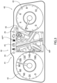
- number 40 indicates a dashboard supported by a dash panel (not shown), which frontally delimits a passenger compartment of a vehicle.
- the dashboard 40 is arranged in front of the driver immediately behind a steering wheel.
- the dashboard 40 comprises a screen 41, which usually is completely programmable (namely, it can be programmed to display any type of information).
- the dashboard 40 comprises at least an analogic pointer instrument 42 (namely, an instrument using a movable pointer) to indicate the measure of the speed of the vehicle and an analogic pointer instrument 43 (namely, an instrument using a movable pointer) to indicate the measure of the number of revolutions per minute of the internal combustion engine 1.
- the dashboard 40 is further provided with a plurality of graphic areas indicated with 44.
- the graphic areas 44 comprises a graphic area 44* where a road map is displayed in order to assist the driver while driving and a graphic area 44** comprising, in turn, a number of indicators 45 (or lights 45) suited to provide the driver with respective items of information of the drive and/or on the state of the vehicle.
- the graphic area 44** comprises an indicator 45 controlled by the electronic control unit ECU and designed to provide indications concerning the burner 21.
- the normal operation of the exhaust gas after-treatment system 14 entails the work conditions disclosed in the description below.
- the electronic control unit ECU is suited to keep the indicator 45 turned on.
- the internal combustion engine 1 is turned off while the burner 21 is caused to turn on.
- the temperature of the pre-catalytic converter 15 and/or of the catalytic converter 17 is lower than an activation temperature and the concentration of pollutants produced by the burner 21 (detected by one of the sensors 18, 19, 20 downstream of the burner 21) is greater than a limit value.
- the starting step starts when the electronic control unit ECU detects the presence of the key and/or when the doors are unlocked through a command of the driver from the remote control.
- the starting step ends when the electronic control unit ECU detects a temperature of the pre-catalytic converter 15 and/or of the catalytic converter 17 higher than or equal to the activation temperature; once the staring step has ended, the electronic control unit ECU is suited to turn off the indicator 45 and the driver can turn on the internal combustion engine 1.
- the electronic control unit ECU is suited to keep the indicator 45 turned on until the following turning off of the internal combustion engine 1.
- the electronic control unit ECU is suited to cause the indicator 45 to turn on so as to warn the driver of the fault/malfunction.
- the indicator 45 is suited to warn the driver of the need to start the burner 21.
- the indicator 45 is turned on when the electronic control unit ECU detects the presence of the key and/or when the doors are unlocked through a command of the driver from the remote control, so that the driver can start the burner 21. Then, the indicator 45 is turned off when the electronic control unit ECU detects a temperature of the pre-catalytic converter 15 and/or of the catalytic converter 17 higher than or equal to the activation temperature.
- the temperature of the pre-catalytic converter 15 and/or of the catalytic converter 17 can alternatively be detected by means of dedicated sensors or estimated by the electronic control unit ECU.
- the electronic control unit ECU disclosed in the description above can be a dedicated control unit ECU, which controls the operation of the burner 21, or can be the electronic control unit ECU controlling the operation of the internal combustion engine 1.
- the connection between the electronic control unit ECU and the indicator 45 can alternatively be obtained by means of a CAN or wired connection.
- the exhaust gas after-treatment system 14 and the method described so far feature several advantages; in particular, they reduce the pollutants released into the atmosphere produced by the burner 21 during the starting step of the burner 21.
Landscapes
- Engineering & Computer Science (AREA)
- Chemical & Material Sciences (AREA)
- Chemical Kinetics & Catalysis (AREA)
- Combustion & Propulsion (AREA)
- Mechanical Engineering (AREA)
- General Engineering & Computer Science (AREA)
- Health & Medical Sciences (AREA)
- Toxicology (AREA)
- Exhaust Gas After Treatment (AREA)
- Testing Of Engines (AREA)
Claims (3)
- Verfahren zur Steuerung eines Abgasnachbehandlungssystems (14) für eine Abgasanlage (2) eines Verbrennungsmotors (1) mit einem Abgaskanal (10); das System (14) umfasst mindestens einen Katalysator (15, 17), der entlang des Abgaskanals (10) angeordnet ist; einen Brenner (21), der geeignet ist, Abgase in den Abgaskanal (10) einzuleiten, und der entlang des Abgaskanals (10) stromaufwärts des mindestens einen Katalysators (15, 17) angeordnet ist und dazu ausgelegt ist, die Erwärmung des mindestens einen Katalysators (15, 17) zu beschleunigen, wobei im Inneren des Brenners (21) eine Verbrennungskammer (22) definiert ist, die Frischluft erhält durch einen Luftzufuhrkreislauf (23), der mit einer Pumpvorrichtung (24) versehen ist, die entlang eines Kanals (25) angeordnet ist, und die Kraftstoff von einer Einspritzdüse (27) erhält, die dazu bestimmt ist, Kraftstoff in die Verbrennungskammer (22) einzuspritzen; eine Zündkerze (28), die mit dem Brenner (21) gekoppelt ist, um die Zündung des in der Verbrennungskammer (22) vorhandenen Gemischs zu bestimmen; und eine Anzeige (45), die in einem Armaturenbrett (40) eines mit dem Verbrennungsmotor (1) versehenen Fahrzeugs untergebracht ist und dazu bestimmt ist, einem Fahrer des Fahrzeugs Angaben über den Brenner (21) bereitzustellen; wobei das Verfahren umfasst:einen Startschritt, bei dem der Verbrennungsmotor (1) abgestellt wird, der Brenner (21) eingeschaltet wird und die Anzeige (45) eingeschaltet wird; wobei der Startschritt beginnt, wenn das Vorhandensein des Schlüssels erkannt wird oder wenn die Türen des Fahrzeugs durch einen Befehl des Fahrers entriegelt werden; und der Startschritt endet, wenn die Temperatur des mindestens einen Katalysators (15, 17) höher als oder gleich einer Aktivierungstemperatur ist; sobald der Startschritt beendet ist, ist eine elektronische Steuereinheit (ECU) geeignet, die Anzeige (45) auszuschalten, und der Fahrer kann den Verbrennungsmotor (1) einschalten;einen normalen Betriebsschritt des Verbrennungsmotors, der sich an den Startschritt anschließt und währenddessen der Verbrennungsmotor (1) läuft; und die Anzeige (45) bleibt eingeschaltet, bis der Verbrennungsmotor (1) abgestellt wird, für den Fall, dass der Verbrennungsmotor (1) gestartet wird, bevor die Temperatur des mindestens einen Katalysators (15, 17) höher als die Aktivierungstemperatur ist.
- Verfahren nach Anspruch 1, ferner umfassend den weiteren Schritt, dass die Anzeige (45) eingeschaltet wird, wenn eine Störung/Fehlfunktion des Brenners (21) erkannt wird, um den Fahrer vor der Störung/Fehlfunktion zu warnen.
- Verfahren nach einem der Ansprüche 1 oder 2, wobei die Temperatur des mindestens einen Katalysators (15, 17) alternativ gemessen oder geschätzt wird.
Applications Claiming Priority (1)
| Application Number | Priority Date | Filing Date | Title |
|---|---|---|---|
| IT102021000020318A IT202100020318A1 (it) | 2021-07-29 | 2021-07-29 | Metodo di controllo di un sistema di post-trattamento dei gas di scarico per un impianto di scarico dei gas esausti di un motore a combustione interna |
Publications (2)
| Publication Number | Publication Date |
|---|---|
| EP4124730A1 EP4124730A1 (de) | 2023-02-01 |
| EP4124730B1 true EP4124730B1 (de) | 2024-05-22 |
Family
ID=78649566
Family Applications (1)
| Application Number | Title | Priority Date | Filing Date |
|---|---|---|---|
| EP22186641.1A Active EP4124730B1 (de) | 2021-07-29 | 2022-07-25 | Verfahren zum steuern eines abgasnachbehandlungssystems für ein abgassystem eines verbrennungsmotors |
Country Status (4)
| Country | Link |
|---|---|
| US (1) | US20230032897A1 (de) |
| EP (1) | EP4124730B1 (de) |
| CN (1) | CN115680835A (de) |
| IT (1) | IT202100020318A1 (de) |
Families Citing this family (2)
| Publication number | Priority date | Publication date | Assignee | Title |
|---|---|---|---|---|
| US12460567B2 (en) * | 2024-01-19 | 2025-11-04 | Ford Global Technologies, Llc | Methods and systems for a fuel operated heater |
| US12442322B1 (en) * | 2024-07-18 | 2025-10-14 | Cummins Emission Solutions Inc. | Vehicle power systems and methods |
Family Cites Families (12)
| Publication number | Priority date | Publication date | Assignee | Title |
|---|---|---|---|---|
| US5379592A (en) * | 1991-10-23 | 1995-01-10 | Waschkuttis; Gerhard | Catalytic converter with ignition burner |
| US5339630A (en) * | 1992-08-28 | 1994-08-23 | General Motors Corporation | Exhaust burner catalyst preheater |
| DE4229595C1 (de) * | 1992-09-04 | 1993-08-19 | Bayerische Motoren Werke Ag, 8000 Muenchen, De | |
| FR2728301B1 (fr) * | 1994-12-19 | 1997-03-14 | Peugeot | Dispositif de traitement des gaz d'echappement d'un moteur a allumage commande comportant un corps catalyseur et un adsorbeur d'hydrocarbures disposes a l'interieur d'un collecteur d'echappement |
| US5896743A (en) * | 1997-06-24 | 1999-04-27 | Heraeus Electro-Nite International N.V. | Catalyst monitor utilizing a lifetime temperature profile for determining efficiency |
| US20050150216A1 (en) * | 2004-01-13 | 2005-07-14 | Crawley Wilbur H. | Method and apparatus for cleaning the electrodes of a fuel-fired burner of an emission abatement assembly |
| KR101401529B1 (ko) * | 2008-04-23 | 2014-06-17 | 에스케이이노베이션 주식회사 | 배기가스 저감장치 및 그 제어방법 |
| US8413423B2 (en) * | 2009-09-01 | 2013-04-09 | GM Global Technologies Operations LLC | Catalyst temperature control systems and methods for hybrid vehicles |
| US9027331B2 (en) * | 2013-02-27 | 2015-05-12 | Tenneco Automotive Operating Company Inc. | Exhaust aftertreatment burner with preheated combustion air |
| US8959902B2 (en) * | 2013-02-27 | 2015-02-24 | Tenneco Automotive Operating Company Inc. | Exhaust treatment burner and mixer system |
| US9657622B2 (en) * | 2013-09-18 | 2017-05-23 | Advanced Technology Emission Solutions Inc. | Catalytic converter system with control and methods for use therewith |
| US10563605B2 (en) * | 2018-03-13 | 2020-02-18 | Ford Global Technologies, Llc | Systems and methods for reducing vehicle emissions |
-
2021
- 2021-07-29 IT IT102021000020318A patent/IT202100020318A1/it unknown
-
2022
- 2022-07-25 EP EP22186641.1A patent/EP4124730B1/de active Active
- 2022-07-27 US US17/815,306 patent/US20230032897A1/en not_active Abandoned
- 2022-07-28 CN CN202210903451.0A patent/CN115680835A/zh active Pending
Also Published As
| Publication number | Publication date |
|---|---|
| EP4124730A1 (de) | 2023-02-01 |
| US20230032897A1 (en) | 2023-02-02 |
| CN115680835A (zh) | 2023-02-03 |
| IT202100020318A1 (it) | 2023-01-29 |
Similar Documents
| Publication | Publication Date | Title |
|---|---|---|
| US8752368B2 (en) | Diagnostic method and diagnostic system for a particle filter of an internal combustion engine, in particular for a soot filter in a diesel motor vehicle | |
| US6865883B2 (en) | System and method for regenerating exhaust system filtering and catalyst components | |
| RU2359142C2 (ru) | Устройство для определения пропусков зажигания для двигателя внутреннего сгорания и способ определения пропусков зажигания в двигателе | |
| EP4124730A1 (de) | Verfahren zum steuern eines abgasnachbehandlungssystems für ein abgassystem eines verbrennungsmotors | |
| US11939903B2 (en) | Method for operating an exhaust burner, apparatus for performing such a method, and motor vehicle | |
| US20180334977A1 (en) | Gasoline particulate filter regeneration strategy | |
| US20100050757A1 (en) | Method and system to determine the efficiency of a diesel oxidation catalyst | |
| US10995645B2 (en) | Exhaust aftertreatment system and method for regenerating a particulate filter | |
| JP4369727B2 (ja) | 排気浄化装置の制御方法 | |
| EP4134527B1 (de) | Verfahren zum steuern eines abgasnachbehandlungssystems für ein abgassystem eines verbrennungsmotors | |
| EP4112900B1 (de) | Verfahren zum steuern eines brenners für eine abgasanlage eines verbrennungsmotors | |
| JPH07127503A (ja) | 内燃機関の排気ガス浄化装置 | |
| EP2538045A1 (de) | Abgasreiniger für einen verbrennungsmotor | |
| JPH03182670A (ja) | 内燃機関の電子制御装置 | |
| US7131321B2 (en) | Throttle system abnormality determination apparatus | |
| WO2019209668A1 (en) | Gasoline particulate filter filtration efficiency improvement with engine control | |
| EP1746274B1 (de) | Verfahren und Vorrichtung zur Regelung der Kraftstoffzumessung | |
| US9528421B2 (en) | Exhaust device of internal combustion engine | |
| CN108952910B (zh) | 用于控制排气后处理装置的旁路的系统和方法 | |
| EP4556691B1 (de) | Verfahren zur bestimmung der sauerstoffspeicherkapazität eines katalysators einer abgasanlage einer brennkraftmaschine | |
| US12364944B2 (en) | Method for monitoring a regeneration of a particulate filter in the exhaust system of an internal combustion engine | |
| JP4163926B2 (ja) | 排気白煙化防止装置 | |
| US20090266050A1 (en) | Method for controlling the regeneration of an electrostatic particle filter | |
| JPH07279651A (ja) | 内燃機関の排気浄化装置 | |
| US20110231079A1 (en) | Method and device for operating an internal combustion engine |
Legal Events
| Date | Code | Title | Description |
|---|---|---|---|
| PUAI | Public reference made under article 153(3) epc to a published international application that has entered the european phase |
Free format text: ORIGINAL CODE: 0009012 |
|
| STAA | Information on the status of an ep patent application or granted ep patent |
Free format text: STATUS: THE APPLICATION HAS BEEN PUBLISHED |
|
| AK | Designated contracting states |
Kind code of ref document: A1 Designated state(s): AL AT BE BG CH CY CZ DE DK EE ES FI FR GB GR HR HU IE IS IT LI LT LU LV MC MK MT NL NO PL PT RO RS SE SI SK SM TR |
|
| STAA | Information on the status of an ep patent application or granted ep patent |
Free format text: STATUS: REQUEST FOR EXAMINATION WAS MADE |
|
| 17P | Request for examination filed |
Effective date: 20230801 |
|
| RBV | Designated contracting states (corrected) |
Designated state(s): AL AT BE BG CH CY CZ DE DK EE ES FI FR GB GR HR HU IE IS IT LI LT LU LV MC MK MT NL NO PL PT RO RS SE SI SK SM TR |
|
| GRAP | Despatch of communication of intention to grant a patent |
Free format text: ORIGINAL CODE: EPIDOSNIGR1 |
|
| STAA | Information on the status of an ep patent application or granted ep patent |
Free format text: STATUS: GRANT OF PATENT IS INTENDED |
|
| INTG | Intention to grant announced |
Effective date: 20240104 |
|
| P01 | Opt-out of the competence of the unified patent court (upc) registered |
Effective date: 20240221 |
|
| GRAS | Grant fee paid |
Free format text: ORIGINAL CODE: EPIDOSNIGR3 |
|
| GRAA | (expected) grant |
Free format text: ORIGINAL CODE: 0009210 |
|
| STAA | Information on the status of an ep patent application or granted ep patent |
Free format text: STATUS: THE PATENT HAS BEEN GRANTED |
|
| AK | Designated contracting states |
Kind code of ref document: B1 Designated state(s): AL AT BE BG CH CY CZ DE DK EE ES FI FR GB GR HR HU IE IS IT LI LT LU LV MC MK MT NL NO PL PT RO RS SE SI SK SM TR |
|
| REG | Reference to a national code |
Ref country code: GB Ref legal event code: FG4D |
|
| REG | Reference to a national code |
Ref country code: CH Ref legal event code: EP |
|
| REG | Reference to a national code |
Ref country code: DE Ref legal event code: R096 Ref document number: 602022003564 Country of ref document: DE |
|
| REG | Reference to a national code |
Ref country code: IE Ref legal event code: FG4D |
|
| REG | Reference to a national code |
Ref country code: LT Ref legal event code: MG9D |
|
| REG | Reference to a national code |
Ref country code: NL Ref legal event code: MP Effective date: 20240522 |
|
| PG25 | Lapsed in a contracting state [announced via postgrant information from national office to epo] |
Ref country code: IS Free format text: LAPSE BECAUSE OF FAILURE TO SUBMIT A TRANSLATION OF THE DESCRIPTION OR TO PAY THE FEE WITHIN THE PRESCRIBED TIME-LIMIT Effective date: 20240922 |
|
| PG25 | Lapsed in a contracting state [announced via postgrant information from national office to epo] |
Ref country code: BG Free format text: LAPSE BECAUSE OF FAILURE TO SUBMIT A TRANSLATION OF THE DESCRIPTION OR TO PAY THE FEE WITHIN THE PRESCRIBED TIME-LIMIT Effective date: 20240522 |
|
| PG25 | Lapsed in a contracting state [announced via postgrant information from national office to epo] |
Ref country code: HR Free format text: LAPSE BECAUSE OF FAILURE TO SUBMIT A TRANSLATION OF THE DESCRIPTION OR TO PAY THE FEE WITHIN THE PRESCRIBED TIME-LIMIT Effective date: 20240522 Ref country code: FI Free format text: LAPSE BECAUSE OF FAILURE TO SUBMIT A TRANSLATION OF THE DESCRIPTION OR TO PAY THE FEE WITHIN THE PRESCRIBED TIME-LIMIT Effective date: 20240522 |
|
| PG25 | Lapsed in a contracting state [announced via postgrant information from national office to epo] |
Ref country code: GR Free format text: LAPSE BECAUSE OF FAILURE TO SUBMIT A TRANSLATION OF THE DESCRIPTION OR TO PAY THE FEE WITHIN THE PRESCRIBED TIME-LIMIT Effective date: 20240823 |
|
| PG25 | Lapsed in a contracting state [announced via postgrant information from national office to epo] |
Ref country code: PT Free format text: LAPSE BECAUSE OF FAILURE TO SUBMIT A TRANSLATION OF THE DESCRIPTION OR TO PAY THE FEE WITHIN THE PRESCRIBED TIME-LIMIT Effective date: 20240923 |
|
| REG | Reference to a national code |
Ref country code: AT Ref legal event code: MK05 Ref document number: 1688937 Country of ref document: AT Kind code of ref document: T Effective date: 20240522 |
|
| PG25 | Lapsed in a contracting state [announced via postgrant information from national office to epo] |
Ref country code: NL Free format text: LAPSE BECAUSE OF FAILURE TO SUBMIT A TRANSLATION OF THE DESCRIPTION OR TO PAY THE FEE WITHIN THE PRESCRIBED TIME-LIMIT Effective date: 20240522 |
|
| PG25 | Lapsed in a contracting state [announced via postgrant information from national office to epo] |
Ref country code: ES Free format text: LAPSE BECAUSE OF FAILURE TO SUBMIT A TRANSLATION OF THE DESCRIPTION OR TO PAY THE FEE WITHIN THE PRESCRIBED TIME-LIMIT Effective date: 20240522 |
|
| PG25 | Lapsed in a contracting state [announced via postgrant information from national office to epo] |
Ref country code: AT Free format text: LAPSE BECAUSE OF FAILURE TO SUBMIT A TRANSLATION OF THE DESCRIPTION OR TO PAY THE FEE WITHIN THE PRESCRIBED TIME-LIMIT Effective date: 20240522 |
|
| PG25 | Lapsed in a contracting state [announced via postgrant information from national office to epo] |
Ref country code: PL Free format text: LAPSE BECAUSE OF FAILURE TO SUBMIT A TRANSLATION OF THE DESCRIPTION OR TO PAY THE FEE WITHIN THE PRESCRIBED TIME-LIMIT Effective date: 20240522 |
|
| PG25 | Lapsed in a contracting state [announced via postgrant information from national office to epo] |
Ref country code: LV Free format text: LAPSE BECAUSE OF FAILURE TO SUBMIT A TRANSLATION OF THE DESCRIPTION OR TO PAY THE FEE WITHIN THE PRESCRIBED TIME-LIMIT Effective date: 20240522 |
|
| PG25 | Lapsed in a contracting state [announced via postgrant information from national office to epo] |
Ref country code: PT Free format text: LAPSE BECAUSE OF FAILURE TO SUBMIT A TRANSLATION OF THE DESCRIPTION OR TO PAY THE FEE WITHIN THE PRESCRIBED TIME-LIMIT Effective date: 20240923 Ref country code: PL Free format text: LAPSE BECAUSE OF FAILURE TO SUBMIT A TRANSLATION OF THE DESCRIPTION OR TO PAY THE FEE WITHIN THE PRESCRIBED TIME-LIMIT Effective date: 20240522 Ref country code: NO Free format text: LAPSE BECAUSE OF FAILURE TO SUBMIT A TRANSLATION OF THE DESCRIPTION OR TO PAY THE FEE WITHIN THE PRESCRIBED TIME-LIMIT Effective date: 20240822 Ref country code: NL Free format text: LAPSE BECAUSE OF FAILURE TO SUBMIT A TRANSLATION OF THE DESCRIPTION OR TO PAY THE FEE WITHIN THE PRESCRIBED TIME-LIMIT Effective date: 20240522 Ref country code: LV Free format text: LAPSE BECAUSE OF FAILURE TO SUBMIT A TRANSLATION OF THE DESCRIPTION OR TO PAY THE FEE WITHIN THE PRESCRIBED TIME-LIMIT Effective date: 20240522 Ref country code: IS Free format text: LAPSE BECAUSE OF FAILURE TO SUBMIT A TRANSLATION OF THE DESCRIPTION OR TO PAY THE FEE WITHIN THE PRESCRIBED TIME-LIMIT Effective date: 20240922 Ref country code: HR Free format text: LAPSE BECAUSE OF FAILURE TO SUBMIT A TRANSLATION OF THE DESCRIPTION OR TO PAY THE FEE WITHIN THE PRESCRIBED TIME-LIMIT Effective date: 20240522 Ref country code: GR Free format text: LAPSE BECAUSE OF FAILURE TO SUBMIT A TRANSLATION OF THE DESCRIPTION OR TO PAY THE FEE WITHIN THE PRESCRIBED TIME-LIMIT Effective date: 20240823 Ref country code: FI Free format text: LAPSE BECAUSE OF FAILURE TO SUBMIT A TRANSLATION OF THE DESCRIPTION OR TO PAY THE FEE WITHIN THE PRESCRIBED TIME-LIMIT Effective date: 20240522 Ref country code: ES Free format text: LAPSE BECAUSE OF FAILURE TO SUBMIT A TRANSLATION OF THE DESCRIPTION OR TO PAY THE FEE WITHIN THE PRESCRIBED TIME-LIMIT Effective date: 20240522 Ref country code: BG Free format text: LAPSE BECAUSE OF FAILURE TO SUBMIT A TRANSLATION OF THE DESCRIPTION OR TO PAY THE FEE WITHIN THE PRESCRIBED TIME-LIMIT Effective date: 20240522 Ref country code: AT Free format text: LAPSE BECAUSE OF FAILURE TO SUBMIT A TRANSLATION OF THE DESCRIPTION OR TO PAY THE FEE WITHIN THE PRESCRIBED TIME-LIMIT Effective date: 20240522 Ref country code: RS Free format text: LAPSE BECAUSE OF FAILURE TO SUBMIT A TRANSLATION OF THE DESCRIPTION OR TO PAY THE FEE WITHIN THE PRESCRIBED TIME-LIMIT Effective date: 20240822 |
|
| PG25 | Lapsed in a contracting state [announced via postgrant information from national office to epo] |
Ref country code: DK Free format text: LAPSE BECAUSE OF FAILURE TO SUBMIT A TRANSLATION OF THE DESCRIPTION OR TO PAY THE FEE WITHIN THE PRESCRIBED TIME-LIMIT Effective date: 20240522 |
|
| PG25 | Lapsed in a contracting state [announced via postgrant information from national office to epo] |
Ref country code: EE Free format text: LAPSE BECAUSE OF FAILURE TO SUBMIT A TRANSLATION OF THE DESCRIPTION OR TO PAY THE FEE WITHIN THE PRESCRIBED TIME-LIMIT Effective date: 20240522 |
|
| PG25 | Lapsed in a contracting state [announced via postgrant information from national office to epo] |
Ref country code: CZ Free format text: LAPSE BECAUSE OF FAILURE TO SUBMIT A TRANSLATION OF THE DESCRIPTION OR TO PAY THE FEE WITHIN THE PRESCRIBED TIME-LIMIT Effective date: 20240522 |
|
| PG25 | Lapsed in a contracting state [announced via postgrant information from national office to epo] |
Ref country code: RO Free format text: LAPSE BECAUSE OF FAILURE TO SUBMIT A TRANSLATION OF THE DESCRIPTION OR TO PAY THE FEE WITHIN THE PRESCRIBED TIME-LIMIT Effective date: 20240522 Ref country code: SK Free format text: LAPSE BECAUSE OF FAILURE TO SUBMIT A TRANSLATION OF THE DESCRIPTION OR TO PAY THE FEE WITHIN THE PRESCRIBED TIME-LIMIT Effective date: 20240522 |
|
| PG25 | Lapsed in a contracting state [announced via postgrant information from national office to epo] |
Ref country code: SK Free format text: LAPSE BECAUSE OF FAILURE TO SUBMIT A TRANSLATION OF THE DESCRIPTION OR TO PAY THE FEE WITHIN THE PRESCRIBED TIME-LIMIT Effective date: 20240522 Ref country code: RO Free format text: LAPSE BECAUSE OF FAILURE TO SUBMIT A TRANSLATION OF THE DESCRIPTION OR TO PAY THE FEE WITHIN THE PRESCRIBED TIME-LIMIT Effective date: 20240522 Ref country code: EE Free format text: LAPSE BECAUSE OF FAILURE TO SUBMIT A TRANSLATION OF THE DESCRIPTION OR TO PAY THE FEE WITHIN THE PRESCRIBED TIME-LIMIT Effective date: 20240522 Ref country code: DK Free format text: LAPSE BECAUSE OF FAILURE TO SUBMIT A TRANSLATION OF THE DESCRIPTION OR TO PAY THE FEE WITHIN THE PRESCRIBED TIME-LIMIT Effective date: 20240522 Ref country code: CZ Free format text: LAPSE BECAUSE OF FAILURE TO SUBMIT A TRANSLATION OF THE DESCRIPTION OR TO PAY THE FEE WITHIN THE PRESCRIBED TIME-LIMIT Effective date: 20240522 |
|
| PG25 | Lapsed in a contracting state [announced via postgrant information from national office to epo] |
Ref country code: MC Free format text: LAPSE BECAUSE OF FAILURE TO SUBMIT A TRANSLATION OF THE DESCRIPTION OR TO PAY THE FEE WITHIN THE PRESCRIBED TIME-LIMIT Effective date: 20240522 |
|
| REG | Reference to a national code |
Ref country code: DE Ref legal event code: R097 Ref document number: 602022003564 Country of ref document: DE |
|
| PG25 | Lapsed in a contracting state [announced via postgrant information from national office to epo] |
Ref country code: LU Free format text: LAPSE BECAUSE OF NON-PAYMENT OF DUE FEES Effective date: 20240725 |
|
| PLBE | No opposition filed within time limit |
Free format text: ORIGINAL CODE: 0009261 |
|
| STAA | Information on the status of an ep patent application or granted ep patent |
Free format text: STATUS: NO OPPOSITION FILED WITHIN TIME LIMIT |
|
| PG25 | Lapsed in a contracting state [announced via postgrant information from national office to epo] |
Ref country code: LU Free format text: LAPSE BECAUSE OF NON-PAYMENT OF DUE FEES Effective date: 20240725 |
|
| PG25 | Lapsed in a contracting state [announced via postgrant information from national office to epo] |
Ref country code: SI Free format text: LAPSE BECAUSE OF FAILURE TO SUBMIT A TRANSLATION OF THE DESCRIPTION OR TO PAY THE FEE WITHIN THE PRESCRIBED TIME-LIMIT Effective date: 20240522 Ref country code: BE Free format text: LAPSE BECAUSE OF NON-PAYMENT OF DUE FEES Effective date: 20240731 |
|
| 26N | No opposition filed |
Effective date: 20250225 |
|
| REG | Reference to a national code |
Ref country code: BE Ref legal event code: MM Effective date: 20240731 |
|
| PGFP | Annual fee paid to national office [announced via postgrant information from national office to epo] |
Ref country code: FR Payment date: 20250620 Year of fee payment: 4 |
|
| PG25 | Lapsed in a contracting state [announced via postgrant information from national office to epo] |
Ref country code: IE Free format text: LAPSE BECAUSE OF NON-PAYMENT OF DUE FEES Effective date: 20240725 |
|
| PG25 | Lapsed in a contracting state [announced via postgrant information from national office to epo] |
Ref country code: SE Free format text: LAPSE BECAUSE OF FAILURE TO SUBMIT A TRANSLATION OF THE DESCRIPTION OR TO PAY THE FEE WITHIN THE PRESCRIBED TIME-LIMIT Effective date: 20240522 |
|
| PGFP | Annual fee paid to national office [announced via postgrant information from national office to epo] |
Ref country code: DE Payment date: 20250620 Year of fee payment: 4 |
|
| PGFP | Annual fee paid to national office [announced via postgrant information from national office to epo] |
Ref country code: IT Payment date: 20250731 Year of fee payment: 4 |
|
| PG25 | Lapsed in a contracting state [announced via postgrant information from national office to epo] |
Ref country code: CY Free format text: LAPSE BECAUSE OF FAILURE TO SUBMIT A TRANSLATION OF THE DESCRIPTION OR TO PAY THE FEE WITHIN THE PRESCRIBED TIME-LIMIT; INVALID AB INITIO Effective date: 20220725 |
|
| REG | Reference to a national code |
Ref country code: CH Ref legal event code: H13 Free format text: ST27 STATUS EVENT CODE: U-0-0-H10-H13 (AS PROVIDED BY THE NATIONAL OFFICE) Effective date: 20260224 |
|
| PG25 | Lapsed in a contracting state [announced via postgrant information from national office to epo] |
Ref country code: HU Free format text: LAPSE BECAUSE OF FAILURE TO SUBMIT A TRANSLATION OF THE DESCRIPTION OR TO PAY THE FEE WITHIN THE PRESCRIBED TIME-LIMIT; INVALID AB INITIO Effective date: 20220725 |
|
| PG25 | Lapsed in a contracting state [announced via postgrant information from national office to epo] |
Ref country code: SM Free format text: LAPSE BECAUSE OF FAILURE TO SUBMIT A TRANSLATION OF THE DESCRIPTION OR TO PAY THE FEE WITHIN THE PRESCRIBED TIME-LIMIT; INVALID AB INITIO Effective date: 20220725 |
|
| PG25 | Lapsed in a contracting state [announced via postgrant information from national office to epo] |
Ref country code: CH Free format text: LAPSE BECAUSE OF NON-PAYMENT OF DUE FEES Effective date: 20250731 |