EP4124520B1 - Dispositif de connexion entre balai d' essuyage et bras d' entraînement - Google Patents
Dispositif de connexion entre balai d' essuyage et bras d' entraînement Download PDFInfo
- Publication number
- EP4124520B1 EP4124520B1 EP22187094.2A EP22187094A EP4124520B1 EP 4124520 B1 EP4124520 B1 EP 4124520B1 EP 22187094 A EP22187094 A EP 22187094A EP 4124520 B1 EP4124520 B1 EP 4124520B1
- Authority
- EP
- European Patent Office
- Prior art keywords
- adapter
- adapters
- connection device
- drive arm
- wiper blade
- Prior art date
- Legal status (The legal status is an assumption and is not a legal conclusion. Google has not performed a legal analysis and makes no representation as to the accuracy of the status listed.)
- Active
Links
Images
Classifications
-
- B—PERFORMING OPERATIONS; TRANSPORTING
- B60—VEHICLES IN GENERAL
- B60S—SERVICING, CLEANING, REPAIRING, SUPPORTING, LIFTING, OR MANOEUVRING OF VEHICLES, NOT OTHERWISE PROVIDED FOR
- B60S1/00—Cleaning of vehicles
- B60S1/02—Cleaning windscreens, windows or optical devices
- B60S1/04—Wipers or the like, e.g. scrapers
- B60S1/32—Wipers or the like, e.g. scrapers characterised by constructional features of wiper blade arms or blades
- B60S1/40—Connections between blades and arms
- B60S1/4003—Multi-purpose connections for two or more kinds of arm ends
-
- B—PERFORMING OPERATIONS; TRANSPORTING
- B60—VEHICLES IN GENERAL
- B60S—SERVICING, CLEANING, REPAIRING, SUPPORTING, LIFTING, OR MANOEUVRING OF VEHICLES, NOT OTHERWISE PROVIDED FOR
- B60S1/00—Cleaning of vehicles
- B60S1/02—Cleaning windscreens, windows or optical devices
- B60S1/04—Wipers or the like, e.g. scrapers
- B60S1/32—Wipers or the like, e.g. scrapers characterised by constructional features of wiper blade arms or blades
- B60S1/40—Connections between blades and arms
- B60S1/4038—Connections between blades and arms for arms provided with a channel-shaped end
- B60S1/4045—Connections between blades and arms for arms provided with a channel-shaped end comprising a detachable intermediate element mounted on the channel-shaped end
- B60S1/4048—Connections between blades and arms for arms provided with a channel-shaped end comprising a detachable intermediate element mounted on the channel-shaped end the element being provided with retention means co-operating with the channel-shaped end of the arm
- B60S2001/4051—Connections between blades and arms for arms provided with a channel-shaped end comprising a detachable intermediate element mounted on the channel-shaped end the element being provided with retention means co-operating with the channel-shaped end of the arm the intermediate element engaging the side walls of the arm
-
- B—PERFORMING OPERATIONS; TRANSPORTING
- B60—VEHICLES IN GENERAL
- B60S—SERVICING, CLEANING, REPAIRING, SUPPORTING, LIFTING, OR MANOEUVRING OF VEHICLES, NOT OTHERWISE PROVIDED FOR
- B60S1/00—Cleaning of vehicles
- B60S1/02—Cleaning windscreens, windows or optical devices
- B60S1/04—Wipers or the like, e.g. scrapers
- B60S1/32—Wipers or the like, e.g. scrapers characterised by constructional features of wiper blade arms or blades
- B60S1/40—Connections between blades and arms
- B60S1/4038—Connections between blades and arms for arms provided with a channel-shaped end
- B60S1/4045—Connections between blades and arms for arms provided with a channel-shaped end comprising a detachable intermediate element mounted on the channel-shaped end
- B60S1/4048—Connections between blades and arms for arms provided with a channel-shaped end comprising a detachable intermediate element mounted on the channel-shaped end the element being provided with retention means co-operating with the channel-shaped end of the arm
- B60S2001/4054—Connections between blades and arms for arms provided with a channel-shaped end comprising a detachable intermediate element mounted on the channel-shaped end the element being provided with retention means co-operating with the channel-shaped end of the arm the intermediate element engaging the back part of the arm
Definitions
- the present invention relates to the field of vehicle windshield wipers, and more particularly to connection devices for connecting a wiper blade to a drive arm.
- Vehicle wiper systems are designed to remove, by sweeping, liquids and dirt that could interfere with a driver's vision.
- These wiper systems generally include a drive arm, which performs an angular back-and-forth movement, and elongated wiper blades equipped with scraper blades made of a resilient material. The scraper blade rubs against the windshield and evacuates these liquids and dirt by sweeping them out of the driver's field of vision.
- the wiper blade is attached to the drive arm by a connection device that includes a connector and an adapter.
- the connector is a part that is secured to the wiper blade and is generally secured to the scraper blade.
- the adapter is a part that is interposed between the drive arm and the connector, being shaped to engage in an end part of the drive arm. The connector and adapter then cooperate to allow the articulated connection and the fixing of the wiper blade on the drive arm, thus forming the connection device of the wiper blade to the drive arm.
- the articulated connection between the connector and the adapter comprises at least one transverse pivot axis of the connector relative to the adapter, which is also a pivot axis of the wiper blade relative to the drive arm.
- One of the members for example the connector, generally comprises a substantially cylindrical shape which forms a pivot and which is received in a housing of complementary shape of the other member, here the adapter.
- An adapter is used to couple a wiper blade to a particular type of yoke or drive arm, and there are several varieties of end pieces. These varieties are similar in appearance but differ from each other in their dimensions, particularly in their widths or lateral dimensions. They also vary in the positions of the holes intended to cooperate with a locking push button on the adapter.
- a connection device can also comprise different adapters which can be associated by fitting into each other, the combination of these different adapters being capable of connecting to a particular type of drive arm to which each adapter taken separately cannot connect, thus multiplying the possibilities of assembling the same wiper blade.
- the association between a particular type of drive arm and a connection device can thus be based on the cooperation between the locking member arranged on the adapter and the orifice of the drive arm in which it is intended to be housed.
- the prior art nevertheless does not propose any other solution than to interchange the adapter according to the type of arm desired, which leads to a certain redundancy of the technical means which define these adapters.
- connection device allowing a superposition between the locking member of a first adapter and the locking member of a second adapter which fits onto this first adapter, the combination of these two adapters allowing them to cooperate with a type of drive arm different from the type of drive arm with which the first adapter taken in isolation can cooperate.
- An example of a connection device for a vehicle is described in the document DE102010030880 .
- An object of the present invention thus relates to a connection device for a vehicle, intended to connect a wiper blade to a drive arm, comprising at least one connector configured to be made integral with the wiper blade and at least two adapters, one of the adapters being configured to connect the connector to a first type of drive arm and a combination of the two adapters being configured to connect the connector to a second type of drive arm.
- each of these adapters comprises a locking member configured to lock the combination of the two adapters to the second type of drive arm, these locking members overlapping to secure the combination of the two adapters to the second type of drive arm and in that the locking members are retractable between a locking position intended to lock the adapters relative to the second type of drive arm and a mounting position intended to allow a translation of the adapters relative to the second type of drive arm.
- the connection device therefore comprises at least one connector and at least two adapters.
- This connector ensures the connection of the connection device to the wiper blade, while the adapters participate in connecting this connector to a particular type of drive arm.
- One of the adapters has a configuration such that it participates in connecting the connector to a first type of drive arm.
- another adapter such as proposed by the invention is added to it, the combination formed by these two adapters participates in connecting the connector to a second type of drive arm, distinct from the first type of drive arm.
- adapters are capable of cooperating with the drive arm adapted to receive this combination of adapters by means of their superimposed locking members, each adapter comprising such a locking member.
- the locking member of one of the adapters comes to overlap the locking member of the other adapter, securing the wiper blade to the drive arm.
- the blocking, or locking corresponds to an engagement of a portion of the locking members in an opening, for example an orifice or a hole, pierced in a wall of a yoke of the drive arm.
- these locking members prevent the translation of the connection device in a longitudinal direction, which corresponds to a direction of elongation of this connection device.
- the connection device must in fact be able, in order to be mounted in the drive arm, to slide therein.
- the locking members protrude from the connection device.
- protruding it is meant that the locking member of one of the adapters protrudes from the plane in which an upper wall of this adapter mainly extends, and that the locking member of the other adapter protrudes from the plane in which an upper wall of this other adapter mainly extends.
- protrusions constitute stop means, which prevent the translation of the connection device.
- the locking members no longer protrude and are thus retracted, and the sliding of the connection device in the yoke of the drive arm is then facilitated.
- each locking member comprises a flexible tab and a push button arranged at a free end of the flexible tab.
- tabs are flexible in the sense that they are elastically deformable in their range of elasticity, allowing in particular the locking members to retract and then return to a so-called locking position.
- the flexible tabs of the locking members are capable of overlapping, and are overlapped when the two adapters are nested.
- the push buttons of the locking members are capable of being superimposed, and are superimposed when the two adapters are nested. It is understood that the push button of one of the adapters can therefore cover, at least in part, in particular vertically, the push button of the other adapter.
- the locking members of the adapters When the locking members of the adapters are not superimposed, they are both in a rest position.
- rest position it is meant that the flexible tabs of these locking members are not elastically deformed, that is to say that they extend substantially in the planes or above the upper walls of the adapters that comprise them.
- the push button of the second adapter covers, at least in part, the push button of the first adapter. This push button of the second adapter then abuts against the push button of the first adapter and causes this flexible tab of the second adapter to come out of the plane in which the upper wall of the second adapter extends.
- the adapters comprise a first adapter and a second adapter, the push button of the first adapter being intended to be housed in an orifice of a yoke of the first type of drive arm, and the push buttons of the first adapter and the second adapter are intended to extend at least partly into a hole of a yoke of the second type of drive arm.
- the push button of the first adapter is configured to be housed in a hole made in the yoke of the first type of drive arm, thereby securing the first adapter to this first type of drive arm.
- the push buttons of each of the adapters are housed, at least in part, in a hole arranged in the yoke of the second type of drive arm. These two push buttons therefore participate in blocking the translation of the connection device.
- the two push buttons extend into the hole arranged in the yoke of the second type of drive arm such that the push button of the second adapter projects above the upper wall of the yoke of the second type of drive arm, while the push button of the first adapter extends at least into the thickness of this upper wall, for example by extending inside a cavity delimited by the push button of the second adapter.
- the push button of the first adapter is in contact with the push button of the second adapter when the locking members overlap.
- Such an overlay allows the combination of adapters to be secured to the second type of drive arm.
- the push button of the second adapter abuts against the push button of the first adapter. Such a stop elastically deforms the flexible tab on which the push button of the second adapter is arranged. Similarly, when the connection device is in the locking position in the drive arm, the stop of the push button of the second adapter against the push button of the first adapter elastically deforms the flexible tab of the first adapter. The push button of the first adapter is then at least partially retracted, i.e. it has not returned to its rest position.
- each adapter has a U-shaped section that delimits a housing, one of the adapters being arranged in the housing of the other adapter.
- the adapters which are therefore substantially U-shaped parts in cross section, can thus fit into each other.
- a U-shaped adapter can cover another U-shaped adapter, facilitating an association of several adapters within the same connection device.
- the adapters are associated with each other by removable interlocking.
- the adapters can thus be easily associated and dissociated, respectively by interlocking one in the housing of the other and by disengagement of one relative to the other.
- Such removable interlocking can in particular be a clipping.
- the invention further relates to a wiper blade comprising a connection device as described above.
- the invention further relates to a wiping system comprising a drive arm carrying a wiper blade comprising a connection device, the wiper blade being connected to the drive arm via the connection device described above.
- a longitudinal direction corresponds to a main direction of elongation of the wiper blade to which the connection device is made integral, this longitudinal direction being parallel to a longitudinal axis L of a reference L, V, T illustrated in the figures.
- a vertical direction corresponds to a direction in which the locking members are superimposed, this vertical direction being parallel to a vertical axis V of the reference L, V, T and this vertical axis V being perpendicular to the longitudinal axis L.
- a transverse direction corresponds to a direction parallel to a transverse axis T of the reference L, V, T, this transverse axis T being perpendicular to the longitudinal axis L and to the vertical axis V.
- the terms “lower” and “upper” relating to the elements of the connection device are understood to refer to the distance of these elements from the wiper blade, a lower end of such elements corresponding to the end arranged in the vicinity of this wiper blade while an upper end corresponds to the end arranged at a distance from the wiper blade.
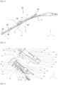
- FIG. 1 thus illustrates a wiping system 10 according to the invention, comprising a wiper blade 12 and a drive arm 59 for the wiper blade 12.
- the wiper blade 12 comprises a longitudinal body 16, a wiping blade 18, generally made of rubber, and at least one vertebra, not visible, which stiffens the wiping blade 18 and facilitates its application to a vehicle windshield.
- the wiper blade 12 schematically shown further comprises end pieces or clips 22 for attaching the wiper blade 18 and the vertebra to the longitudinal body 16, these end pieces 22 being located at each of the longitudinal ends of the longitudinal body 16.
- the wiper blade 12 carries, substantially in its middle, a connection device 1 according to the invention.
- This connection device 1 comprises in particular a connector 24, and at least two adapters.
- the adapters 25 and 29 participate in connecting the connector 24 to a particular type of drive arm, which is here a second type of drive arm 59.
- the adapters 25 and 29 are mounted on the connector 24 so as to maintain a degree of freedom in pivoting about a hinge axis Y which is a transverse axis substantially perpendicular to the longitudinal axis of the wiper blade 12. This degree of freedom allows the wiper blade 12 to pivot relative to the drive arm 59 and thus allows the wiper blade 12 to follow the curvature of the windshield during its movements.
- the adapters 25 and 29 can be detached from the drive arm 59, for example by pressing an actuation button, here a push button 891 carried by the second adapter 29.
- the drive arm 59 is driven by a motor, not shown, to follow an angular back-and-forth movement to evacuate water, and possibly other undesirable elements covering the windshield.
- the adapters 25 and 29 ensure the connection of the wiper blade 12 to the drive arm 59. More particularly, they participate in the connection of a head or yoke 28 of the drive arm 59, which can be formed in one piece with the drive arm 59 or even be added and fixed on a rod thereof.
- the yoke 28 has an elongated shape in a general direction substantially parallel to the longitudinal direction of the wiper blade 12.
- the yoke 28 is extended, at one of its longitudinal ends, by a connecting part 30 to the rod of the drive arm 59.
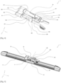
- FIG 2 shows a perspective view of the first adapter 25 and the second adapter 29 making up the connection device 1 of the figure 1 .
- the first adapter 25 extends mainly in the longitudinal direction, and has a substantially U-shaped cross section.
- This first adapter 25 can in particular, when it constitutes the only adapter of a connection device, participate in connecting the connector 24 to a first type of drive arm, not illustrated in the present figure. It may also, when used in combination with the second adapter 29, participate in connecting the connector 24 to a second type of drive arm, the drive arm 59 of the figure 1 .
- This first adapter 25 has a body 254 which comprises a first side wall 251 and a second side wall 252 substantially parallel to each other, at a distance from each other. These walls 251, 252 are connected to each other by an upper wall 250 which is substantially perpendicular to them.
- the walls 250, 251, 252 of this first adapter 25 have an elongated shape in the longitudinal direction, and they define between them an internal housing 253 intended to accommodate the connector 24.
- the side walls 251 and 252 are also equipped respectively with a first through-hole 451 and a second through-hole 452, open onto the internal housing 253.
- the first orifice 451 is substantially circular while the second orifice 452 is substantially parallelepipedal.
- These orifices 451 and 452 define a pivot axis of the first adapter 25 relative to the connector 24, not shown in the present figure, and by extension of the wiper blade 12 connected to the first adapter 25 relative to the drive arm connected to the connector 24.
- the body 254 of the first adapter 25 is connected to a head 255, the vertical and transverse dimensions of which are greater than those of the body 254 of the first adapter 25. It is thus understood that the head 255 extends beyond a longitudinal and transverse plane in which the upper wall 250 extends, and beyond a longitudinal and vertical plane in which the side walls 251 and 252 extend.
- the head 255 is in particular a locking means. Indeed, when the wiper blade 12 is assembled on the drive arm 59 by means of the connection device 1 as illustrated in the figure 1 , this head 255 forms a stop for the yoke 28 of the drive arm 59, thus preventing the translation of the latter beyond the body 254 of the first adapter 25.
- the upper wall 250 of the first adapter 25 narrows so as to form a point 257, which is in cantilevered relative to the body 255.
- the body 254 of the first adapter 25 and more particularly the side walls 251, 252 are each continued by an elastically deformable leg 256.
- These legs 256 can thus be brought closer to each other by elastic deformation.
- the legs 256 are substantially symmetrical along a plane of symmetry extending in longitudinal and vertical directions, located equidistant from the first side wall 251 and the second side wall 252.
- Each leg 256 further has a locking portion 456, shaped to cooperate with notches arranged on the yoke 28 of the drive arm 59 in order to lock the assembly of the first adapter 25 with the latter, thus constituting another locking means.
- the upper wall 250 is pierced with a first opening 259, a second opening 359 and a third opening 459, aligned in the longitudinal direction and opening onto the internal housing 253.
- the third opening 459 which is in the vicinity of the legs 256, is partly covered by a locking member 85.
- This locking member 85 comprises in particular a flexible tab 850 and a push button 851.
- This tab 850 extends mainly in the longitudinal direction and has a fixed end 853 at a distance from the legs 256, which is connected to the side wall 251 and to the side wall 252 by a bridge, and a free end 852, movable, in the vicinity of the legs 256.
- the tab 850 is elastically deformable and its free end 852 carries the push button 851.
- the tab 850 and the push button 851 can thus pivot about an axis A, located at the fixed end 853 which then plays a role of hinge for the locking member.
- the tab 850 is arranged in such a way that the push button 851 is located above a plane in which the upper wall 250 extends. This means that the push button 851 is at a distance from this upper wall 250 of the first adapter 25 in the vertical direction, opposite the internal housing 253.
- the push button 851 retracts to slide into this yoke and engages by elastic snap-fastening in a corresponding orifice of the yoke where it is housed in order to lock the first adapter 25 with respect to the latter.
- the second adapter 29 is a part whose cross section is substantially U-shaped.
- This second adapter 29 comprises an upper wall 290 as well as a first side wall 291 and a second side wall 292.
- the upper wall 290 extends mainly in a longitudinal direction and in a transverse direction, while the side walls 291 and 292 extend mainly in a longitudinal direction and a vertical direction.
- the side walls 291 and 292 are thus parallel to each other and perpendicular to the upper wall 290.
- These walls 290, 291 and 292 define an internal housing 293, this internal housing being in particular capable of receiving a connector 24 or another adapter.
- the second adapter 29 has a shoulder 301, which comprises a curved tab 296 extending from one of the longitudinal ends of the second adapter 29 and at a distance therefrom.
- This curved tab 296 participates in the assembly of the second adapter 29 with other parts and in particular with other adapters, such as for example the first adapter 25.
- This first adapter 25 in fact has, on one of the internal faces of its head 255 not visible on the figure 2 , an internal portion capable of receiving this curved tab 296 of the second adapter 29, thus forming a locking means.
- the upper wall 290 of the second adapter 29 is pierced with two parallel slots 294, arranged on the upper wall 290 in the vicinity of each of the side walls 291 and 292. These parallel slots 294 are aligned according to the transverse direction and open onto the internal housing 293. These parallel slots 294 open, at a longitudinal end of the second adapter 29 which does not carry the curved tab 296, onto an opening 297 also pierced in the upper wall 290.
- This opening 297 is partly covered by a locking member 89 constituting the second adapter 29.
- This locking member 89 comprises in particular a flexible tab 890 and a push button 891.
- This tab 890 is connected to the upper wall 290 of the second adapter 29 by a first end 893, and has a free end 892, at a distance from the longitudinal end which carries the curved tab 296 greater than the distance which separates this curved tab 296 from the first end 893.
- the tab 890 is elastically deformable, and its free end 892 carries the push button 891.
- the tab 890 and the push button 891 can thus pivot about an axis B, located at the first fixed end 893 which acts as a hinge. At rest, that is to say without constraint, the tab 890 is arranged in such a way that the push button 891 is located above the plane in which the upper wall 290 extends. It is understood that the push button 891 is at a distance from this upper wall 290 in the vertical direction, opposite the internal housing 293.
- FIG 3 is a perspective representation of a combination of the first adapter 25 and the second adapter 29 of the figure 2 .
- These two adapters 25 and 29 are here shown nested, as they are in the connection device 1 according to the invention.
- This is a removable nesting, that is to say that the adapters 25 and 29 can be alternately associated and dissociated, without destroying one or the other.
- This removable nesting can for example be a clipping.
- the first adapter 25 and the second adapter 29 both having U-shaped sections which delimit their respective internal housings 253 and 293, these adapters 25 and 29 can nest one inside the other.
- the first adapter 25 which is arranged in the internal housing 293 of the second adapter 29.
- the locking member 89 of the second adapter 29 is superimposed on the locking member 85 of the first adapter 25, thus making it possible to secure the combination of these adapters 25 and 29 to the second type of drive arm 59, shown in figure 5 .
- the tab 890 of the second adapter 29 covers the tab 850 of the first adapter 25.
- the push buttons 851 and 891 being able to overlap, the push button 891 of the second adapter 29 at least partially covers the push button 851 of the first adapter 25.
- connection device 1 is here secured to a wiper blade 12.
- the first adapter 25 comprises at least one pivot connection 31 mechanically connecting it to the connector 24, at its orifices 451 and 452.
- This pivot connection 31 constitutes an articulation which ensures the rotation of the connector 24 relative to the first adapter 25.
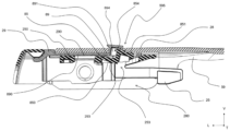
- FIG 5 is a sectional view of the combination of the first adapter 25 and the second adapter 29 of the figure 3 , this combination being here illustrated mounted in the second type of drive arm 59, and more particularly in the yoke 28 of this second type of drive arm 59.
- the locking member 85 of the first adapter 25 and the locking member 89 of the second adapter 29 are retractable between a position for locking the adapters 25 and 29 relative to the second drive arm 59 and a position for mounting these adapters 25 and 29 relative to this second drive arm 59.
- the mounting position corresponds to the position that the locking members 85 and 89 take when the adapters 25 and 29 are being inserted into the drive arm 59, and more precisely into the yoke 28 of this drive arm 59.
- the locking position corresponds to the position that the locking members 85 and 89 take once the adapters 25 and 29 are mounted in this yoke 28 of the drive arm 59, the translation of the adapters 25 and 29 in a longitudinal direction then being prevented by the locking members 85 and 89 combined with each other.
- the flexible tabs 850 and 890 of the locking members 85 and 89 are elastically deformed such that the tab 850 is no longer in the same plane as the upper wall 250 of the first adapter 25, and in the same way that the tab 890 is no longer in the same plane as the upper wall 290 of the second adapter 29.
- the push buttons 851 and 891 then retract into the internal housings 253 and 293 respectively, and therefore no longer protrude relative to these planes.
- the adapters 25 and 29 which they equip can then be inserted into the yoke 28 of the drive arm 59 without the translation necessary for such insertion being blocked by these projections.
- the push buttons 851 and 891 project relative to the planes in which the upper walls 250 and 290 of their respective adapters extend.
- the tab 890 of the second adapter 29 is aligned, in the longitudinal direction, with the upper wall 290 of the second adapter 29; both are in the same plane.
- the tab 850 of the first adapter 25 is not aligned with the upper wall 250 thereof in the longitudinal direction. This tab 850 of the first adapter 25 is in fact elastically deformed so that the push button 851 which it carries is, at least in part, retracted into the internal housing 253 of the first adapter 25.
- the push buttons 851 and 891 extend at least partly into a hole 595 of the yoke 28 of the second drive arm 59.
- These locking members 85 and 89 overlap in order to secure the combination of the adapters 25 and 29 to the drive arm 59, the push button 851 of the first adapter 25 being in contact with the push button 891 of the second adapter 29.
- This push button 85 of the first adapter 25 pushes the push button 89 of the second adapter 29 through the hole 595, towards the outside of a receiving cavity 280 of the yoke 28 in which the adapters 25 and 29 are located.
- the push button 891 of the second adapter 29 abuts against the thickness of the upper wall of the yoke 28.
- the push button 851 of the first adapter 25 extends into the thickness of this upper wall of the yoke 28.
- a nose 854 of the push button 851 of the first adapter 25 extends into a cavity 894 of the push button 891 of the second adapter 29.
- the push buttons 851 and 891 participate in blocking the translation in the longitudinal direction of the adapters 25 and 29 within the second drive arm 59.
- the present invention thus proposes a connection device in which the superposition of the locking members of a first adapter and a second adapter makes it possible to connect a wiper blade to a particular type of drive arm, such a drive arm being different from the type of drive arm with which the first adapter, alone, can cooperate.
Landscapes
- Engineering & Computer Science (AREA)
- Mechanical Engineering (AREA)
- Pivots And Pivotal Connections (AREA)
- Snaps, Bayonet Connections, Set Pins, And Snap Rings (AREA)
Applications Claiming Priority (1)
| Application Number | Priority Date | Filing Date | Title |
|---|---|---|---|
| FR2108308A FR3125779B1 (fr) | 2021-07-30 | 2021-07-30 | Dispositif de connexion entre balai d’essuyage et bras d’entraînement |
Publications (2)
| Publication Number | Publication Date |
|---|---|
| EP4124520A1 EP4124520A1 (fr) | 2023-02-01 |
| EP4124520B1 true EP4124520B1 (fr) | 2024-11-20 |
Family
ID=77519393
Family Applications (1)
| Application Number | Title | Priority Date | Filing Date |
|---|---|---|---|
| EP22187094.2A Active EP4124520B1 (fr) | 2021-07-30 | 2022-07-26 | Dispositif de connexion entre balai d' essuyage et bras d' entraînement |
Country Status (5)
| Country | Link |
|---|---|
| US (1) | US11772610B2 (enExample) |
| EP (1) | EP4124520B1 (enExample) |
| JP (1) | JP2023021096A (enExample) |
| CN (1) | CN115675369A (enExample) |
| FR (1) | FR3125779B1 (enExample) |
Family Cites Families (8)
| Publication number | Priority date | Publication date | Assignee | Title |
|---|---|---|---|---|
| DE102010003269A1 (de) * | 2010-03-25 | 2011-09-29 | Robert Bosch Gmbh | Adapter zum gelenkigen Verbinden eines Verbindungselements am Ende eines Wischarms mit einem Anschlusselement eines Wischblatts |
| DE102010030880A1 (de) * | 2010-07-02 | 2012-01-05 | Robert Bosch Gmbh | Anschlussvorrichtung zum gelenkigen Verbinden eines Wischarms mit einem Wischblatt |
| GB2497037B (en) * | 2010-09-15 | 2016-01-20 | Trico Products Corp | Universal coupler for a beam blade windshield wiper assembly |
| US9173813B2 (en) * | 2011-02-12 | 2015-11-03 | Eca Medical Instruments | Medical tool and waste collection device |
| CN203005370U (zh) * | 2012-12-26 | 2013-06-19 | 美途汽配实业(厦门)有限公司 | 雨刷连接装置 |
| US9365190B2 (en) | 2013-10-01 | 2016-06-14 | Xiamen Meto Auto Parts Industry Co., Ltd. | Connecting device of windshield wiper |
| PL3169566T3 (pl) * | 2014-07-16 | 2020-04-30 | Federal-Mogul S.A. | Urządzenie wycieraczkowe szyby przedniej pojazdu |
| FR3112738B1 (fr) * | 2020-07-22 | 2022-07-15 | Valeo Systemes Dessuyage | Dispositif de connexion d’un balai d’essuyage à un bras d’essuie-glace |
-
2021
- 2021-07-30 FR FR2108308A patent/FR3125779B1/fr active Active
-
2022
- 2022-07-26 EP EP22187094.2A patent/EP4124520B1/fr active Active
- 2022-07-28 US US17/815,762 patent/US11772610B2/en active Active
- 2022-07-29 JP JP2022122197A patent/JP2023021096A/ja active Pending
- 2022-07-29 CN CN202210907303.6A patent/CN115675369A/zh active Pending
Also Published As
| Publication number | Publication date |
|---|---|
| US20230036036A1 (en) | 2023-02-02 |
| FR3125779A1 (fr) | 2023-02-03 |
| EP4124520A1 (fr) | 2023-02-01 |
| FR3125779B1 (fr) | 2024-05-24 |
| US11772610B2 (en) | 2023-10-03 |
| CN115675369A (zh) | 2023-02-03 |
| JP2023021096A (ja) | 2023-02-09 |
Similar Documents
| Publication | Publication Date | Title |
|---|---|---|
| EP2027000B1 (fr) | Dispositif de fixation d'un balai d'essuie-glace sur un bras | |
| EP1140592B1 (fr) | Essuie-glace de vehicule automobile comportant des moyens perfectionnes d'articulation du balai sur le bras d'essuie-glace | |
| EP3118070B1 (fr) | Organe pour un système de connexion d'un balai d'essuie-glace | |
| EP3168092B1 (fr) | Organe pour un système de connexion d'un balai d'essuie-glace à un bras d'entraînement | |
| EP2755874B1 (fr) | Ensemble de connexion pour systeme d'essuyage d'un vehicule automobile | |
| EP3112223B1 (fr) | Organe pour un système de connexion d'un balai d'essuie-glace à de multiples bras d'essuie-glace | |
| EP3165415A1 (fr) | Adaptateur pour un essuie-glace de véhicule automobile | |
| WO2016005103A1 (fr) | Adaptateur de liaison d'un balai d'essuie-glace à un bras d'entraînement de ce balai | |
| EP4124520B1 (fr) | Dispositif de connexion entre balai d' essuyage et bras d' entraînement | |
| EP3112224A1 (fr) | Adaptateur pour relier un balai d'essuyage à un bras d'entraînement | |
| EP3251904A1 (fr) | Adaptateur de raccordement de l'extrémité libre d'un bras d'essuie-glace, ensemble comportant un tel adaptateur et un bras d'essuie-glace | |
| EP3112225A1 (fr) | Organe pour un système de connexion d'un balai d'essuie-glace à de multiples bras d'essuie-glace | |
| EP4124521B1 (fr) | Dispositif de connexion entre balai d' essuyage et bras d' entraînement | |
| EP4124518A1 (fr) | Dispositif de connexion entre balai d' essuyage et bras d' entraînement | |
| EP4279342A1 (fr) | Dispositif de connexion d'un balai d' essuyage | |
| EP3112228B1 (fr) | Organe pour un système de connexion d'un balai d'essuyage à un bras d'essuie-glace | |
| FR3091237A1 (fr) | Système d’essuyage pour véhicule automobile composé d’un adaptateur, d’une chape et d’un dispositif de verrouillage de l’adaptateur dans la chape | |
| EP2755875B1 (fr) | Adaptateur a languettes flexibles pour systeme d'essuyage | |
| WO2025247817A1 (fr) | Dispositif de connexion d'un balai d'essuyage | |
| FR3037898A1 (fr) | Organe pour un systeme de connexion d'un balai d'essuyage a un bras d'essuie-glace | |
| EP3248848B1 (fr) | Dispositif de fixation pour le montage d'un balai d'essuie-glace sur un bras d'entrainement, et système d'essuyage correspondant | |
| EP0578563A1 (fr) | Balai d'essuie-glace | |
| WO2023222838A1 (fr) | Module de connexion d'un système d'essuyage. | |
| FR3091232A1 (fr) | Ensemble de fixation pour système d’essuyage de véhicule automobile | |
| FR3135679A1 (fr) | Dispositif de connexion d’un balai d’essuyage. |
Legal Events
| Date | Code | Title | Description |
|---|---|---|---|
| PUAI | Public reference made under article 153(3) epc to a published international application that has entered the european phase |
Free format text: ORIGINAL CODE: 0009012 |
|
| STAA | Information on the status of an ep patent application or granted ep patent |
Free format text: STATUS: THE APPLICATION HAS BEEN PUBLISHED |
|
| AK | Designated contracting states |
Kind code of ref document: A1 Designated state(s): AL AT BE BG CH CY CZ DE DK EE ES FI FR GB GR HR HU IE IS IT LI LT LU LV MC MK MT NL NO PL PT RO RS SE SI SK SM TR |
|
| STAA | Information on the status of an ep patent application or granted ep patent |
Free format text: STATUS: REQUEST FOR EXAMINATION WAS MADE |
|
| 17P | Request for examination filed |
Effective date: 20230731 |
|
| RBV | Designated contracting states (corrected) |
Designated state(s): AL AT BE BG CH CY CZ DE DK EE ES FI FR GB GR HR HU IE IS IT LI LT LU LV MC MK MT NL NO PL PT RO RS SE SI SK SM TR |
|
| GRAP | Despatch of communication of intention to grant a patent |
Free format text: ORIGINAL CODE: EPIDOSNIGR1 |
|
| STAA | Information on the status of an ep patent application or granted ep patent |
Free format text: STATUS: GRANT OF PATENT IS INTENDED |
|
| RIC1 | Information provided on ipc code assigned before grant |
Ipc: B60S 1/40 20060101AFI20240508BHEP |
|
| INTG | Intention to grant announced |
Effective date: 20240610 |
|
| GRAS | Grant fee paid |
Free format text: ORIGINAL CODE: EPIDOSNIGR3 |
|
| GRAA | (expected) grant |
Free format text: ORIGINAL CODE: 0009210 |
|
| STAA | Information on the status of an ep patent application or granted ep patent |
Free format text: STATUS: THE PATENT HAS BEEN GRANTED |
|
| AK | Designated contracting states |
Kind code of ref document: B1 Designated state(s): AL AT BE BG CH CY CZ DE DK EE ES FI FR GB GR HR HU IE IS IT LI LT LU LV MC MK MT NL NO PL PT RO RS SE SI SK SM TR |
|
| REG | Reference to a national code |
Ref country code: GB Ref legal event code: FG4D Free format text: NOT ENGLISH |
|
| REG | Reference to a national code |
Ref country code: CH Ref legal event code: EP |
|
| REG | Reference to a national code |
Ref country code: DE Ref legal event code: R096 Ref document number: 602022007837 Country of ref document: DE |
|
| REG | Reference to a national code |
Ref country code: IE Ref legal event code: FG4D Free format text: LANGUAGE OF EP DOCUMENT: FRENCH |
|
| REG | Reference to a national code |
Ref country code: LT Ref legal event code: MG9D |
|
| REG | Reference to a national code |
Ref country code: NL Ref legal event code: MP Effective date: 20241120 |
|
| PG25 | Lapsed in a contracting state [announced via postgrant information from national office to epo] |
Ref country code: IS Free format text: LAPSE BECAUSE OF FAILURE TO SUBMIT A TRANSLATION OF THE DESCRIPTION OR TO PAY THE FEE WITHIN THE PRESCRIBED TIME-LIMIT Effective date: 20250320 Ref country code: PT Free format text: LAPSE BECAUSE OF FAILURE TO SUBMIT A TRANSLATION OF THE DESCRIPTION OR TO PAY THE FEE WITHIN THE PRESCRIBED TIME-LIMIT Effective date: 20250320 Ref country code: HR Free format text: LAPSE BECAUSE OF FAILURE TO SUBMIT A TRANSLATION OF THE DESCRIPTION OR TO PAY THE FEE WITHIN THE PRESCRIBED TIME-LIMIT Effective date: 20241120 |
|
| PG25 | Lapsed in a contracting state [announced via postgrant information from national office to epo] |
Ref country code: FI Free format text: LAPSE BECAUSE OF FAILURE TO SUBMIT A TRANSLATION OF THE DESCRIPTION OR TO PAY THE FEE WITHIN THE PRESCRIBED TIME-LIMIT Effective date: 20241120 Ref country code: NL Free format text: LAPSE BECAUSE OF FAILURE TO SUBMIT A TRANSLATION OF THE DESCRIPTION OR TO PAY THE FEE WITHIN THE PRESCRIBED TIME-LIMIT Effective date: 20241120 |
|
| REG | Reference to a national code |
Ref country code: AT Ref legal event code: MK05 Ref document number: 1743319 Country of ref document: AT Kind code of ref document: T Effective date: 20241120 |
|
| PG25 | Lapsed in a contracting state [announced via postgrant information from national office to epo] |
Ref country code: BG Free format text: LAPSE BECAUSE OF FAILURE TO SUBMIT A TRANSLATION OF THE DESCRIPTION OR TO PAY THE FEE WITHIN THE PRESCRIBED TIME-LIMIT Effective date: 20241120 |
|
| PG25 | Lapsed in a contracting state [announced via postgrant information from national office to epo] |
Ref country code: ES Free format text: LAPSE BECAUSE OF FAILURE TO SUBMIT A TRANSLATION OF THE DESCRIPTION OR TO PAY THE FEE WITHIN THE PRESCRIBED TIME-LIMIT Effective date: 20241120 |
|
| PG25 | Lapsed in a contracting state [announced via postgrant information from national office to epo] |
Ref country code: NO Free format text: LAPSE BECAUSE OF FAILURE TO SUBMIT A TRANSLATION OF THE DESCRIPTION OR TO PAY THE FEE WITHIN THE PRESCRIBED TIME-LIMIT Effective date: 20250220 |
|
| PG25 | Lapsed in a contracting state [announced via postgrant information from national office to epo] |
Ref country code: AT Free format text: LAPSE BECAUSE OF FAILURE TO SUBMIT A TRANSLATION OF THE DESCRIPTION OR TO PAY THE FEE WITHIN THE PRESCRIBED TIME-LIMIT Effective date: 20241120 Ref country code: GR Free format text: LAPSE BECAUSE OF FAILURE TO SUBMIT A TRANSLATION OF THE DESCRIPTION OR TO PAY THE FEE WITHIN THE PRESCRIBED TIME-LIMIT Effective date: 20250221 Ref country code: LV Free format text: LAPSE BECAUSE OF FAILURE TO SUBMIT A TRANSLATION OF THE DESCRIPTION OR TO PAY THE FEE WITHIN THE PRESCRIBED TIME-LIMIT Effective date: 20241120 |
|
| PG25 | Lapsed in a contracting state [announced via postgrant information from national office to epo] |
Ref country code: PL Free format text: LAPSE BECAUSE OF FAILURE TO SUBMIT A TRANSLATION OF THE DESCRIPTION OR TO PAY THE FEE WITHIN THE PRESCRIBED TIME-LIMIT Effective date: 20241120 |
|
| PG25 | Lapsed in a contracting state [announced via postgrant information from national office to epo] |
Ref country code: RS Free format text: LAPSE BECAUSE OF FAILURE TO SUBMIT A TRANSLATION OF THE DESCRIPTION OR TO PAY THE FEE WITHIN THE PRESCRIBED TIME-LIMIT Effective date: 20250220 |
|
| PG25 | Lapsed in a contracting state [announced via postgrant information from national office to epo] |
Ref country code: SM Free format text: LAPSE BECAUSE OF FAILURE TO SUBMIT A TRANSLATION OF THE DESCRIPTION OR TO PAY THE FEE WITHIN THE PRESCRIBED TIME-LIMIT Effective date: 20241120 |
|
| PG25 | Lapsed in a contracting state [announced via postgrant information from national office to epo] |
Ref country code: DK Free format text: LAPSE BECAUSE OF FAILURE TO SUBMIT A TRANSLATION OF THE DESCRIPTION OR TO PAY THE FEE WITHIN THE PRESCRIBED TIME-LIMIT Effective date: 20241120 |
|
| PG25 | Lapsed in a contracting state [announced via postgrant information from national office to epo] |
Ref country code: EE Free format text: LAPSE BECAUSE OF FAILURE TO SUBMIT A TRANSLATION OF THE DESCRIPTION OR TO PAY THE FEE WITHIN THE PRESCRIBED TIME-LIMIT Effective date: 20241120 |
|
| PG25 | Lapsed in a contracting state [announced via postgrant information from national office to epo] |
Ref country code: RO Free format text: LAPSE BECAUSE OF FAILURE TO SUBMIT A TRANSLATION OF THE DESCRIPTION OR TO PAY THE FEE WITHIN THE PRESCRIBED TIME-LIMIT Effective date: 20241120 |
|
| PG25 | Lapsed in a contracting state [announced via postgrant information from national office to epo] |
Ref country code: SK Free format text: LAPSE BECAUSE OF FAILURE TO SUBMIT A TRANSLATION OF THE DESCRIPTION OR TO PAY THE FEE WITHIN THE PRESCRIBED TIME-LIMIT Effective date: 20241120 |
|
| PG25 | Lapsed in a contracting state [announced via postgrant information from national office to epo] |
Ref country code: CZ Free format text: LAPSE BECAUSE OF FAILURE TO SUBMIT A TRANSLATION OF THE DESCRIPTION OR TO PAY THE FEE WITHIN THE PRESCRIBED TIME-LIMIT Effective date: 20241120 |
|
| PG25 | Lapsed in a contracting state [announced via postgrant information from national office to epo] |
Ref country code: IT Free format text: LAPSE BECAUSE OF FAILURE TO SUBMIT A TRANSLATION OF THE DESCRIPTION OR TO PAY THE FEE WITHIN THE PRESCRIBED TIME-LIMIT Effective date: 20241120 |
|
| REG | Reference to a national code |
Ref country code: DE Ref legal event code: R097 Ref document number: 602022007837 Country of ref document: DE |
|
| PG25 | Lapsed in a contracting state [announced via postgrant information from national office to epo] |
Ref country code: SE Free format text: LAPSE BECAUSE OF FAILURE TO SUBMIT A TRANSLATION OF THE DESCRIPTION OR TO PAY THE FEE WITHIN THE PRESCRIBED TIME-LIMIT Effective date: 20241120 |
|
| PLBE | No opposition filed within time limit |
Free format text: ORIGINAL CODE: 0009261 |
|
| STAA | Information on the status of an ep patent application or granted ep patent |
Free format text: STATUS: NO OPPOSITION FILED WITHIN TIME LIMIT |
|
| PGFP | Annual fee paid to national office [announced via postgrant information from national office to epo] |
Ref country code: DE Payment date: 20250711 Year of fee payment: 4 |
|
| PGFP | Annual fee paid to national office [announced via postgrant information from national office to epo] |
Ref country code: FR Payment date: 20250730 Year of fee payment: 4 |
|
| 26N | No opposition filed |
Effective date: 20250821 |