EP4124389B1 - System zum filtern eines aerosols mittels einer vielzahl von abscheidern durch zykloneffekt und entsprechendes filterverfahren - Google Patents
System zum filtern eines aerosols mittels einer vielzahl von abscheidern durch zykloneffekt und entsprechendes filterverfahren Download PDFInfo
- Publication number
- EP4124389B1 EP4124389B1 EP22182128.3A EP22182128A EP4124389B1 EP 4124389 B1 EP4124389 B1 EP 4124389B1 EP 22182128 A EP22182128 A EP 22182128A EP 4124389 B1 EP4124389 B1 EP 4124389B1
- Authority
- EP
- European Patent Office
- Prior art keywords
- feed channel
- cyclone separators
- cyclone
- flow
- aerosol
- Prior art date
- Legal status (The legal status is an assumption and is not a legal conclusion. Google has not performed a legal analysis and makes no representation as to the accuracy of the status listed.)
- Active
Links
Images

Classifications
-
- B—PERFORMING OPERATIONS; TRANSPORTING
- B04—CENTRIFUGAL APPARATUS OR MACHINES FOR CARRYING-OUT PHYSICAL OR CHEMICAL PROCESSES
- B04C—APPARATUS USING FREE VORTEX FLOW, e.g. CYCLONES
- B04C5/00—Apparatus in which the axial direction of the vortex is reversed
- B04C5/02—Construction of inlets by which the vortex flow is generated, e.g. tangential admission, the fluid flow being forced to follow a downward path by spirally wound bulkheads, or with slightly downwardly-directed tangential admission
- B04C5/04—Tangential inlets
-
- B—PERFORMING OPERATIONS; TRANSPORTING
- B01—PHYSICAL OR CHEMICAL PROCESSES OR APPARATUS IN GENERAL
- B01D—SEPARATION
- B01D45/00—Separating dispersed particles from gases or vapours by gravity, inertia, or centrifugal forces
- B01D45/12—Separating dispersed particles from gases or vapours by gravity, inertia, or centrifugal forces by centrifugal forces
-
- B—PERFORMING OPERATIONS; TRANSPORTING
- B04—CENTRIFUGAL APPARATUS OR MACHINES FOR CARRYING-OUT PHYSICAL OR CHEMICAL PROCESSES
- B04C—APPARATUS USING FREE VORTEX FLOW, e.g. CYCLONES
- B04C5/00—Apparatus in which the axial direction of the vortex is reversed
- B04C5/08—Vortex chamber constructions
- B04C5/081—Shapes or dimensions
-
- B—PERFORMING OPERATIONS; TRANSPORTING
- B04—CENTRIFUGAL APPARATUS OR MACHINES FOR CARRYING-OUT PHYSICAL OR CHEMICAL PROCESSES
- B04C—APPARATUS USING FREE VORTEX FLOW, e.g. CYCLONES
- B04C5/00—Apparatus in which the axial direction of the vortex is reversed
- B04C5/12—Construction of the overflow ducting, e.g. diffusing or spiral exits
- B04C5/13—Construction of the overflow ducting, e.g. diffusing or spiral exits formed as a vortex finder and extending into the vortex chamber; Discharge from vortex finder otherwise than at the top of the cyclone; Devices for controlling the overflow
-
- B—PERFORMING OPERATIONS; TRANSPORTING
- B04—CENTRIFUGAL APPARATUS OR MACHINES FOR CARRYING-OUT PHYSICAL OR CHEMICAL PROCESSES
- B04C—APPARATUS USING FREE VORTEX FLOW, e.g. CYCLONES
- B04C5/00—Apparatus in which the axial direction of the vortex is reversed
- B04C5/24—Multiple arrangement thereof
- B04C5/28—Multiple arrangement thereof for parallel flow
Definitions
- the invention relates to a filtration system and a filtration method.
- oil mists In many technical fields, it is known to inject oil to facilitate a cutting, engraving, cooling or surface treatment operation.
- the injected oil is often in the form of droplets that saturate the atmosphere of the cutting, engraving, cooling or surface treatment equipment. These oil-laden atmospheres are called oil mists.
- Filtration systems are known that perform filtration by cyclone effect. Separation by cyclone effect allows to have a separation of the carrier gas and oil droplets without using one or more filters that become clogged and must therefore be cleaned regularly.
- the separation efficiency is a function of the centrifugal acceleration undergone by the droplets, the number of revolutions made in the cyclone, their density and their size. There is therefore an interest in looking for a cyclone configuration which is best suited to the oil droplets.
- the filtration efficiency is greater when the speeds are high or the number of cyclones is high. An optimum must therefore be found between complexity of implementation and energy consumption.
- An object of the invention is to provide a filtration system which has a better ratio between energy consumption and its compactness while maintaining the provision of good separation between the particles and the gaseous medium of the aerosol.
- a plurality of cyclone separators of the plurality of cyclone separators and their respective inlets are arranged consecutively along the feed channel and on the same side of the feed channel.
- Two consecutive inlets of two cyclone separators of the plurality of cyclone separators on the same side of the feed channel are arranged at different heights and/or have different cross-sections.
- the feed channel is obstructed or reduced by a plurality of flow diverters, each flow diverter being configured to divert part of a flow of atmosphere loaded with oil droplets towards one of the corresponding cyclone separators.
- the feed channel is connected to N cyclone separators and in which each flow diverter diverts 1/N of the initial section of the feed channel to a corresponding cyclone separator and reduces the section of the feed channel by a value equal to 1/N for the cyclone separators to follow according to the direction of advancement of the aerosol flow.
- the filtration system is made up of only two parts, a first part defining the lower part of the cyclone separators, the lower part of the feed channel and possibly the flow separators if applicable, the second part forming a cover closing the feed channel and closing the cyclone separators.
- the invention also relates to a filtration method which is efficient and simple to use.
- the aerosol is an oil mist and oil is recovered at the outlet of the separators by cyclone effect.
- the filtration system is a filtration system 1 of an aerosol.
- the aerosol is formed by a set of particles in the solid or liquid state which are suspended in a gaseous medium.
- the filtration system is a filtration system of an atmosphere loaded with oil droplets.
- the filtration system is configured to separate the oil present in the atmosphere in the form of droplets and the carrier gas which can be air.
- the carrier gas supports the oil droplets.
- the filtration system is configured to facilitate the recovery of the particles and more particularly of the oil.
- the particles are discharged through a first outlet 2.
- the carrier gas is discharged through another outlet 3 and can also be discharged in part through the first outlet.
- the particles are discharged through an outlet lower while the carrier gas is discharged through an upper outlet to take advantage of the difference in density between these two components.
- the lower outlet is at a lower altitude than the upper outlet.
- the filtration system 1 comprises a supply channel 4 having a first end intended to be connected to a supply member configured to supply an aerosol to be treated which is for example the source of an atmosphere loaded with oil droplets.
- the supply channel 4 receives a mixture containing a carrier gas and particles, for example droplets.
- the aerosol is an oil mist, the latter can be supplied from equipment using the oil and forming the oil mist.
- the aerosol is supplied by a tank receiving the atmosphere to be treated.
- the arrow illustrated in figure 1 represents the direction of flow of an oil mist in the supply channel 4.
- the aerosol is set in motion by means of a ventilation system, for example a fan.
- the ventilation system is arranged upstream and/or downstream of the filtration system 1 so that the aerosol enters the filtration system 1 with a certain speed.
- the feed channel 4 is connected to a plurality of cyclone separators 5.
- a cyclone separator 5 has an inlet 5a receiving the mixture to be separated and it has two separate outlets.
- Each cyclone separator 5 has a first outlet 2 for recovering the particles of the aerosol, preferably the oil and a second outlet 3 for recovering the carrier gas devoid of oil or with an oil content lower than the oil content at the inlet 5a.
- the cyclone separator 5 takes advantage of the effect of gravity to separate the particles and the carrier gas.
- each cyclone separator 5 is connected to the feed channel 4 so that each cyclone separator 5 receives a fraction of the flow of the atmosphere to be treated.
- the cyclone separators 5 are not connected in series but in parallel. The cyclone separators 5 receive the same atmosphere to be treated or substantially the same atmosphere to be treated on their inputs 5a.
- a cyclone separator 5 is a separator that has an inlet 5a engaging in a cone or in a structure having substantially the shape of a cone.
- the upper part of the cyclone separator 5 has a circular cylindrical section while the lower part has a conical and more particularly frustoconical section.
- the lower end of the cyclone separator 5 is open so as to form the outlet 2 intended for the extraction of the oil.
- the upper part of the cyclone separator 5 is covered by a cover 6 which defines a through opening. The through opening forms the outlet 3 for the carrier gas having a low oil content.
- the cyclone separators are identical.
- a cyclone separator 5 having a small diameter.
- the cyclone separators 5 In order to facilitate the feeding of the cyclone separators 5, it is advantageous to mount the cyclone separators 5 consecutively along the feed channel 4.
- the inlets 5a of the cyclone separators 5 are arranged consecutively along the feed channel 4. It is It is also advantageous to have a straight or slightly curved feed channel 4 to limit the pressure loss along the feed channel 4.
- the feed channel 4 is divided into multiple portions which each feed a cyclone separator 5.
- the filtration system 1 has an even number of cyclone separators 5.
- the cyclone separators 5 are distributed symmetrically with respect to the longitudinal direction of the feed channel 4 so as not to disturb the flow of the particle-laden atmosphere. It is advantageous to take two identical portions of the carrier gas flow symmetrically with respect to the median longitudinal plane of the feed channel 4 so as not to disturb the flow and to facilitate obtaining a controlled flow in the cyclone separator 5. In other words, the same quantity of flow is taken on the right side and the left side of the feed channel 4.
- cyclone separators 5 transversely to the feed channel 4, i.e. in the direction of the width of the feed channel 4.
- the separators are arranged in a staggered manner. In this way, with the same length of the feed channel 4, it is possible to connect more cyclone separators 5 without increasing the width of the filtration system too much.
- two consecutive inlets 5a of two cyclone separators 5 of the plurality of cyclone separators 5 on the same side of the feed channel 4 are arranged consecutively and at different heights.
- the two inlets 5a are arranged at different levels.
- the first inlet 5a is at a lower level of the feed channel 4 and the second inlet 5a is at a higher level of the feed channel 4.
- the offset of the inlets 5a on the height of the feed channel 4 makes it possible to improve the capture of the carrier gas flow by limiting the disturbances on the flow for other inputs to follow. Height is measured in a vertical direction.
- a plurality of flow diverters 7 are present which divert the flow of carrier gases towards the cyclone separator inlets 5.
- the diverters are installed in the feed channel 4 or they are formed by the side wall 4a of the feed channel. In the embodiment illustrated in figure 1 , the diverters are formed by the side wall 4a of the feed channel 4.
- the flow diverters 7 obstruct or reduce the active section of the feed channel 4 to divert a portion of the flow to the cyclone separator 5 to be fed and reduce the section of the feed channel 4 for the cyclone separators 5 to follow along the longitudinal direction of the feed channel 4.
- the flow separators 7 define a curved wall so as to shift the direction of the carrier gas flow between the feed channel 4 and the cyclone separator 5 so that the carrier gas flowing in the longitudinal direction flows tangentially in the cyclone separator 5. This allows for more efficient separation.
- the filtration system 1 has a first number of cyclone separators 5, for example N cyclone separators 5, arranged on one side of the feed channel 4.
- the inlets 5a of the cyclone separators 5 are distributed in the height direction over the first number of stages, i.e. N stages.
- the N inlets 5a define N different stages for capturing the carrier gas flow.
- the carrier gas flow is diverted in each of the cyclone separators 5 by means of said first number of flow deflectors 7, i.e. N flow deflectors 7.
- the N flow deflectors 7 are arranged consecutively along the longitudinal axis of the feed channel and the N flow deflectors reduce the cross-section of the feed channel by a value equal to 1/N.
- Each flow diverter feeds a cyclone separator 5 with a gas flow which represents 1/N of the initial flow that fills the feed channel.
- each flow diverter 7 obstructs or reduces the cross-section of the feed channel 4 by a value equal to 1/N for the remainder of the feed channel.
- the active cross-section of the feed channel 4 decreases each time a portion of the carrier gas flow is diverted to a cyclone separator 5.
- Each inlet 5a has a height h which corresponds to H/N with H the initial height of the supply channel 4.
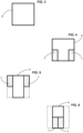
- FIG. 2 represents the distribution of the various flow deflectors 7 in the feed channel 4.
- the eight flow deflectors 7 corresponding to the eight cyclone separators 5 have a total deflection section which is equal to the initial section of the feed channel 4.
- the series of flow deflectors 7 extend from the side walls towards the centre of the feed channel 4. In a series, the flow deflectors are arranged one above the other.
- FIG 3 represents a section of the inlet of the supply channel 4 which defines the value of the initial section of the supply channel 4.
- the figure 4 represents a sectional view of the feed channel at the start-up of the first two flow diverters intended to feed the first two cyclone separators 5.
- the figure 5 represents a sectional view of the feed channel at the start-up of the two second flow diverters intended to feed the two second cyclone separators 5.
- the feed channel has been reduced in section by the first two flow separators.
- the filtration system 1 has a first number of cyclone separators 5, for example N cyclone separators 5, arranged on one side of the feed channel 4.
- the number of cyclone separators 5 is an even number.
- the inlets of the cyclone separators 5 are distributed over a second number of stages which corresponds to half of the first number, i.e. N/2 stages.
- the carrier gas flow is diverted in each of the cyclone separators 5 by means of said first number of flow diverters 7, i.e. N flow diverters 7.
- the N flow diverters 7 are arranged consecutively along the longitudinal axis of the feed channel 4 and the N flow diverters reduce the active section of the feed channel 4 by a value equal to 1/N.
- Each flow diverter 7 feeds a cyclone separator 5 with a gas flow which represents 1/N of the initial flow which fills the feed channel 4.
- the N flow diverters 7 are divided into two series of second number of flow diverters 7, i.e. N/2. Each of the series extends from one end to the other according to the height of the feed channel 4. Each of the two series of flow diverters 7 defines N/2 stages.
- the section of the feed channel 4 is divided into two equal portions according to the height, i.e. according to a direction parallel to the central axis.
- each inlet series captures a section of the initial flow from one side wall of the feed channel to the opposite side wall.
- FIG 1 illustrates a configuration of filtration system 1 with eight cyclone separators 5. Only the four cyclone separators on the left side are shown. The four inlets 5a are divided into two sets of two inlets 5a.
- the figure 2 illustrates a view of the various flow diverters 7 in the feed channel 4. The eight flow diverters 7 occupy a section equal to the section of the feed channel 4 to divert all the flow towards the cyclone separators 5.
- the filtration system 1 has a first number of cyclone separators 5, for example N cyclone separators 5, arranged on one side of the feed channel 4.
- the inlets of the cyclone separators 5 are divided into n series of inlets with n series of flow diverters 7.
- Each of the n series of inlets has N/n inlets with N/n flow diverters 7.
- Each flow diverter 7 feeds a cyclone separator 5 with a gas flow which represents 1/N of the initial flow which fills the feed channel 4.
- Each series of flow diverters 7 occupies 1/n of the cross-section of the feed channel 4 relative to the initial cross-section of the feed channel 4.
- the carrier gas flow is diverted in each of the cyclone separators 5 by means of said first number of flow diverters 7, i.e. N flow diverters 7.
- the N flow diverters are arranged consecutively along the longitudinal axis of the feed channel 4 and the N flow diverters 7 reduce the cross-section of the feed channel 4 by a value equal to 1/N.
- the operation is identical to that of the previous embodiment.
- the filtration system has 2N cyclone separators.
- the 2N cyclone separators are divided into N cyclone separators on the right side of the feed channel 4 and N separators on the left side of the feed channel 4.
- the N inlets 5a and the N flow separators are distributed in n series, with n a non-zero integer, for example 1, 2 or 3.
- N is also a non-zero integer.
- the different cyclone effect separators 5 all have the same deflection section value.
- Such a configuration makes it possible to optimize the section of the feed channel to feed each of the cyclone effect separators 5.
- the deflection section defined by a flow deflector 7 has a height h which is greater than the width, preferably the height h is at least twice the width.
- the filtration system 1 has eight cyclone separators with four cyclone separators on each side of the feed channel.
- Such a configuration makes it possible to have a section close to the square which is preferential for feeding the cyclone separators 5.
- the number of separators to be used and their distribution define the section of the feed channel 4 or the section of the feed channel defines the number of cyclone separators 5 to be used.
- the filtration system 1 is formed by only two parts made of polymer material and which can be obtained by injection.
- the first part defines the feed channel 4 as well as the cyclone separators 5 and the flow deflectors 7 if necessary.
- the second part forms the cover 6 with the outlet orifice 3 for the carrier gas. It is then particularly economical to form a high-performance separation system 1 for the separation of air and oil from an oil mist.
- the filtration of an oil mist and more generally of an aerosol is carried out by injecting the mist at the inlet of the supply channel 4.
- the flow of oil mist is divided into a plurality of elementary flows which each feed a cyclone separator 5.
- Each cyclone separator 5 carries out the filtration to extract the oil which comes out through a dedicated outlet.
- the multiple cyclone separators 5 are mounted in parallel and are compactly integrated into the filtration system, which makes it possible to form a small-sized yet highly efficient filtration system.
- the separation system can be used to separate particles from an aerosol, where the aerosol may contain particles in a solid state and/or particles in a liquid state.
Landscapes
- Physics & Mathematics (AREA)
- Chemical & Material Sciences (AREA)
- Chemical Kinetics & Catalysis (AREA)
- Geometry (AREA)
- Fluid Mechanics (AREA)
- Separating Particles In Gases By Inertia (AREA)
- Cyclones (AREA)
- Filtering Of Dispersed Particles In Gases (AREA)
Claims (8)
- Filtriersystem (1) für ein mit einem Trägergas und Partikeln versehenes Aerosol, umfassend:- einen Zuführkanal (4) mit einem ersten Ende, das dazu bestimmt ist, mit einem Versorgungsorgan verbunden zu sein, das dazu konfiguriert ist, das Aerosol bereitzustellen;- eine Vielzahl von Zyklonabscheidern (5), wobei jeder Zyklonabscheider (5) einen Einlass (5a) aufweist, der in den Zuführkanal (4) mündet;
wobei mehrere Zyklonabscheider (5) von der Vielzahl von Zyklonabscheidern (5) und ihre jeweiligen Einlässe (5a) entlang des Zuführkanals (4) und auf derselben Seite des Zuführkanals (4) aufeinanderfolgend angeordnet sind;- Deflektoren (7), die im Zuführkanal (4) angeordnet sind, um einen Teil einer Strömung der tröpfchenbeladenen Atmosphäre zu einem der entsprechenden Zyklonabscheider (5) abzulenken,wobei der Querschnitt des Zuführkanals (4) in einer Richtung, die sich vom ersten Ende zu der Vielzahl von Zyklonabscheidern (5) entfernt, abnehmend ist; wobei das Filtriersystem (1) dadurch gekennzeichnet ist, dass Deflektoren (7) im Zuführkanal (4) angeordnet sind, um den aktiven Querschnitt des Zuführkanals (4) auf monotone Weise zu reduzieren, wobei der aktive Querschnitt des Zuführkanals (4) jedes Mal abnimmt, wenn ein Teil des Trägergasstroms durch einen der Deflektoren zu einem Zyklonabscheider abgelenkt wird;und dass zwei aufeinanderfolgende Einlässe von zwei Zyklonabscheidern (5) von der Vielzahl von Zyklonabscheidern (5) auf einer selben Seite des Zuführkanals (4) in unterschiedlichen Höhen angeordnet sind. - Filtriersystem (1) nach Anspruch 1, wobei zwei aufeinanderfolgende Deflektoren die gleiche Dicke haben und in unterschiedlichen Höhen angeordnet sind, die jeweils der Höhe den entsprechenden Deflektoren entsprechen.
- Filtriersystem (1) nach einem der Ansprüche 1 und 2, wobei der Zuführkanal (4) mit N Zyklonabscheidern verbunden ist, und wobei jeder Deflektor (7) 1/N des Anfangsquerschnitts des Zuführkanals (4) zu einem entsprechenden Zyklonabscheider ablenkt und den Querschnitt des Zuführkanals für die nachfolgenden Zyklonabscheider in der Strömungsrichtung des Aerosolstroms um 1/N reduziert.
- System nach einem der vorherigen Ansprüche, wobei die Vielzahl von Zyklonabscheidern (5) in zwei Reihen von Zyklonabscheidern unterteilt ist, die sich senkrecht zu einer Strömungsachse des Aerosols gegenüberliegen, und wobei zwei senkrecht zur Strömungsachse des Aerosols gegenüberliegende Einlässe auf gleicher Höhe liegen.
- System nach einem der vorherigen Ansprüche, das nur aus zwei Teilen aufgebaut ist, wobei ein erstes Teil den unteren Teil der Zyklonabscheider (5), den unteren Teil des Zuführkanals (4) und gegebenenfalls die Deflektoren (7) definiert, wobei das zweite Teil eine Abdeckung bildet, die den Zuführkanal (4) verschließt und die Zyklonabscheider (5) verschließt.
- System nach einem der vorherigen Ansprüche, wobei die zwei aufeinanderfolgenden Einlässe von zwei Zyklonabscheidern (5) von der Vielzahl von Zyklonabscheidern (5) auf einer selben Seite des Zuführkanals (4) unterschiedliche Querschnitte haben.
- Filtrierverfahren, umfassend die folgenden Schritte:- Bereitstellen eines Filtersystems nach einem der vorherigen Ansprüche;- Versorgen des Filtriersystems mit einem Aerosol;- Rückgewinnen der Partikel am Ausgang der Zyklonabscheider (5).
- Filtrierverfahren nach dem vorherigen Anspruch, wobei das Aerosol ein Ölnebel ist und am Ausgang der Zyklonabscheider (5) Öl zurückgewonnen wird.
Applications Claiming Priority (1)
| Application Number | Priority Date | Filing Date | Title |
|---|---|---|---|
| FR2108178A FR3125729B1 (fr) | 2021-07-27 | 2021-07-27 | Système de filtration d’un aérosol au moyen d’une pluralité de séparateurs par effet cyclone et procédé de filtration |
Publications (3)
| Publication Number | Publication Date |
|---|---|
| EP4124389A1 EP4124389A1 (de) | 2023-02-01 |
| EP4124389B1 true EP4124389B1 (de) | 2025-02-12 |
| EP4124389C0 EP4124389C0 (de) | 2025-02-12 |
Family
ID=77711152
Family Applications (1)
| Application Number | Title | Priority Date | Filing Date |
|---|---|---|---|
| EP22182128.3A Active EP4124389B1 (de) | 2021-07-27 | 2022-06-30 | System zum filtern eines aerosols mittels einer vielzahl von abscheidern durch zykloneffekt und entsprechendes filterverfahren |
Country Status (2)
| Country | Link |
|---|---|
| EP (1) | EP4124389B1 (de) |
| FR (1) | FR3125729B1 (de) |
Families Citing this family (1)
| Publication number | Priority date | Publication date | Assignee | Title |
|---|---|---|---|---|
| FR3164401A1 (fr) * | 2024-07-15 | 2026-01-16 | Siebec | Système de filtration d’un aérosol au moyen d’une pluralité de séparateurs par effet cyclone et procédé de filtration |
Family Cites Families (3)
| Publication number | Priority date | Publication date | Assignee | Title |
|---|---|---|---|---|
| US4389307A (en) * | 1981-06-22 | 1983-06-21 | Queen's University At Kingston | Arrangement of multiple fluid cyclones |
| JPH09164344A (ja) * | 1995-12-15 | 1997-06-24 | Toyo Gijutsu Kogyo Kk | サイクロン型集塵装置 |
| US7931719B2 (en) * | 2007-12-03 | 2011-04-26 | National Tank Company | Revolution vortex tube gas/liquids separator |
-
2021
- 2021-07-27 FR FR2108178A patent/FR3125729B1/fr active Active
-
2022
- 2022-06-30 EP EP22182128.3A patent/EP4124389B1/de active Active
Also Published As
| Publication number | Publication date |
|---|---|
| EP4124389A1 (de) | 2023-02-01 |
| FR3125729B1 (fr) | 2025-11-07 |
| FR3125729A1 (fr) | 2023-02-03 |
| EP4124389C0 (de) | 2025-02-12 |
Similar Documents
| Publication | Publication Date | Title |
|---|---|---|
| CA2316742C (fr) | Membrane pour filtration tangentielle et son procede de fabrication | |
| EP0037347B1 (de) | Verfahren und Vorrichtung zur Abscheidung von Partikeln in einem Fluidum, insbesondere zur Reinigung von Suspensionen in der Papierindustrie | |
| EP2106297B1 (de) | Vorrichtung und verfahren zur trennung einer fliessenden medienmischung von einem stationären zyklon | |
| CN104540570B (zh) | 惯性气液分离器及用在惯性气液分离器中的多孔收集基体 | |
| EP3938675B1 (de) | Separatoranordnung und verwendung der anordnung für separation und aufsammlung von bremsstaub | |
| EP0228097B1 (de) | Rotierender Vortex-Separator für eine heterogene Flüssigkeit | |
| EP0971783B1 (de) | Verfahren und einrichtung zur entfernung von tröpfchen oder teilchen aus einem gasstrom | |
| EP4124389B1 (de) | System zum filtern eines aerosols mittels einer vielzahl von abscheidern durch zykloneffekt und entsprechendes filterverfahren | |
| FR2972365A1 (fr) | Separateur a ecoulement cyclonique. | |
| EP3268110B1 (de) | Vorrichtung zum abscheiden von öl aus gas im kurbelgehäuse einer brennkraftmaschine | |
| EP0359682A1 (de) | Vorrichtung zur selektiven Abscheidung von Partikeln in einem Fluidum, insbesondere zur Reinigung von Suspensionen in der Papierindustrie | |
| FR2884857A1 (fr) | Dispositif a elements de separation par voie inertielle pour le filtrage et l'elimination de particules contenues dans des gaz d'echappement | |
| FR2472406A1 (fr) | Procede et installation pour separer des substances a l'aide de la force centrifuge | |
| FR2588779A1 (fr) | Separateur a vortex pour liquide heterogene a debit variable | |
| WO2016198654A1 (fr) | Installation, procédé de dénitration thermique, utilisation d'une telle installation et produit obtenu par un tel procédé | |
| FR2588778A1 (fr) | Separateur a vortex liquide | |
| EP4681821A1 (de) | Aerosolfiltrationssystem mit mehreren zyklonabscheidern und filtrationsverfahren | |
| US20180050347A1 (en) | Fluid Separator Methods and Systems | |
| FR2473349A1 (fr) | Procede pour separer le liquide d'un melange de gaz et de liquide et separateur pour la realisation de ce procede | |
| US9345990B2 (en) | Method and apparatus for separation of components of differing buoyancy mixed into a flowing fluid | |
| EP3624952B1 (de) | Spender für mehrphasige flüssigkeit | |
| FR2912931A1 (fr) | Dispositif pour separer des molecules et/ou particules dispersees dans un fluide | |
| FR2857274A1 (fr) | Purgeur pour des installations de conditionnement d'air | |
| FR3157232A1 (fr) | Procédé de dépoussiérage de fibres au moyen d’un purificateur cyclonique à double paroi | |
| FR2723855A1 (fr) | Dispositif de decantation compact |
Legal Events
| Date | Code | Title | Description |
|---|---|---|---|
| PUAI | Public reference made under article 153(3) epc to a published international application that has entered the european phase |
Free format text: ORIGINAL CODE: 0009012 |
|
| STAA | Information on the status of an ep patent application or granted ep patent |
Free format text: STATUS: THE APPLICATION HAS BEEN PUBLISHED |
|
| AK | Designated contracting states |
Kind code of ref document: A1 Designated state(s): AL AT BE BG CH CY CZ DE DK EE ES FI FR GB GR HR HU IE IS IT LI LT LU LV MC MK MT NL NO PL PT RO RS SE SI SK SM TR |
|
| STAA | Information on the status of an ep patent application or granted ep patent |
Free format text: STATUS: REQUEST FOR EXAMINATION WAS MADE |
|
| 17P | Request for examination filed |
Effective date: 20230801 |
|
| RBV | Designated contracting states (corrected) |
Designated state(s): AL AT BE BG CH CY CZ DE DK EE ES FI FR GB GR HR HU IE IS IT LI LT LU LV MC MK MT NL NO PL PT RO RS SE SI SK SM TR |
|
| GRAP | Despatch of communication of intention to grant a patent |
Free format text: ORIGINAL CODE: EPIDOSNIGR1 |
|
| STAA | Information on the status of an ep patent application or granted ep patent |
Free format text: STATUS: GRANT OF PATENT IS INTENDED |
|
| INTG | Intention to grant announced |
Effective date: 20240124 |
|
| GRAJ | Information related to disapproval of communication of intention to grant by the applicant or resumption of examination proceedings by the epo deleted |
Free format text: ORIGINAL CODE: EPIDOSDIGR1 |
|
| STAA | Information on the status of an ep patent application or granted ep patent |
Free format text: STATUS: REQUEST FOR EXAMINATION WAS MADE |
|
| INTC | Intention to grant announced (deleted) | ||
| RAP3 | Party data changed (applicant data changed or rights of an application transferred) |
Owner name: SIEBEC |
|
| GRAP | Despatch of communication of intention to grant a patent |
Free format text: ORIGINAL CODE: EPIDOSNIGR1 |
|
| STAA | Information on the status of an ep patent application or granted ep patent |
Free format text: STATUS: GRANT OF PATENT IS INTENDED |
|
| INTG | Intention to grant announced |
Effective date: 20240627 |
|
| GRAS | Grant fee paid |
Free format text: ORIGINAL CODE: EPIDOSNIGR3 |
|
| GRAJ | Information related to disapproval of communication of intention to grant by the applicant or resumption of examination proceedings by the epo deleted |
Free format text: ORIGINAL CODE: EPIDOSDIGR1 |
|
| GRAL | Information related to payment of fee for publishing/printing deleted |
Free format text: ORIGINAL CODE: EPIDOSDIGR3 |
|
| STAA | Information on the status of an ep patent application or granted ep patent |
Free format text: STATUS: REQUEST FOR EXAMINATION WAS MADE |
|
| GRAP | Despatch of communication of intention to grant a patent |
Free format text: ORIGINAL CODE: EPIDOSNIGR1 |
|
| STAA | Information on the status of an ep patent application or granted ep patent |
Free format text: STATUS: GRANT OF PATENT IS INTENDED |
|
| INTC | Intention to grant announced (deleted) | ||
| INTG | Intention to grant announced |
Effective date: 20241018 |
|
| GRAA | (expected) grant |
Free format text: ORIGINAL CODE: 0009210 |
|
| STAA | Information on the status of an ep patent application or granted ep patent |
Free format text: STATUS: THE PATENT HAS BEEN GRANTED |
|
| AK | Designated contracting states |
Kind code of ref document: B1 Designated state(s): AL AT BE BG CH CY CZ DE DK EE ES FI FR GB GR HR HU IE IS IT LI LT LU LV MC MK MT NL NO PL PT RO RS SE SI SK SM TR |
|
| REG | Reference to a national code |
Ref country code: GB Ref legal event code: FG4D Free format text: NOT ENGLISH |
|
| REG | Reference to a national code |
Ref country code: CH Ref legal event code: EP |
|
| REG | Reference to a national code |
Ref country code: DE Ref legal event code: R096 Ref document number: 602022010400 Country of ref document: DE |
|
| REG | Reference to a national code |
Ref country code: IE Ref legal event code: FG4D Free format text: LANGUAGE OF EP DOCUMENT: FRENCH |
|
| U01 | Request for unitary effect filed |
Effective date: 20250213 |
|
| U07 | Unitary effect registered |
Designated state(s): AT BE BG DE DK EE FI FR IT LT LU LV MT NL PT RO SE SI Effective date: 20250220 |
|
| PG25 | Lapsed in a contracting state [announced via postgrant information from national office to epo] |
Ref country code: RS Free format text: LAPSE BECAUSE OF FAILURE TO SUBMIT A TRANSLATION OF THE DESCRIPTION OR TO PAY THE FEE WITHIN THE PRESCRIBED TIME-LIMIT Effective date: 20250512 |
|
| PG25 | Lapsed in a contracting state [announced via postgrant information from national office to epo] |
Ref country code: PL Free format text: LAPSE BECAUSE OF FAILURE TO SUBMIT A TRANSLATION OF THE DESCRIPTION OR TO PAY THE FEE WITHIN THE PRESCRIBED TIME-LIMIT Effective date: 20250212 |
|
| PG25 | Lapsed in a contracting state [announced via postgrant information from national office to epo] |
Ref country code: ES Free format text: LAPSE BECAUSE OF FAILURE TO SUBMIT A TRANSLATION OF THE DESCRIPTION OR TO PAY THE FEE WITHIN THE PRESCRIBED TIME-LIMIT Effective date: 20250212 |
|
| PG25 | Lapsed in a contracting state [announced via postgrant information from national office to epo] |
Ref country code: NO Free format text: LAPSE BECAUSE OF FAILURE TO SUBMIT A TRANSLATION OF THE DESCRIPTION OR TO PAY THE FEE WITHIN THE PRESCRIBED TIME-LIMIT Effective date: 20250512 Ref country code: IS Free format text: LAPSE BECAUSE OF FAILURE TO SUBMIT A TRANSLATION OF THE DESCRIPTION OR TO PAY THE FEE WITHIN THE PRESCRIBED TIME-LIMIT Effective date: 20250612 |
|
| PG25 | Lapsed in a contracting state [announced via postgrant information from national office to epo] |
Ref country code: HR Free format text: LAPSE BECAUSE OF FAILURE TO SUBMIT A TRANSLATION OF THE DESCRIPTION OR TO PAY THE FEE WITHIN THE PRESCRIBED TIME-LIMIT Effective date: 20250212 |
|
| PG25 | Lapsed in a contracting state [announced via postgrant information from national office to epo] |
Ref country code: GR Free format text: LAPSE BECAUSE OF FAILURE TO SUBMIT A TRANSLATION OF THE DESCRIPTION OR TO PAY THE FEE WITHIN THE PRESCRIBED TIME-LIMIT Effective date: 20250513 |
|
| U20 | Renewal fee for the european patent with unitary effect paid |
Year of fee payment: 4 Effective date: 20250627 |
|
| PG25 | Lapsed in a contracting state [announced via postgrant information from national office to epo] |
Ref country code: SM Free format text: LAPSE BECAUSE OF FAILURE TO SUBMIT A TRANSLATION OF THE DESCRIPTION OR TO PAY THE FEE WITHIN THE PRESCRIBED TIME-LIMIT Effective date: 20250212 |
|
| PGFP | Annual fee paid to national office [announced via postgrant information from national office to epo] |
Ref country code: CH Payment date: 20250707 Year of fee payment: 4 |
|
| PG25 | Lapsed in a contracting state [announced via postgrant information from national office to epo] |
Ref country code: CZ Free format text: LAPSE BECAUSE OF FAILURE TO SUBMIT A TRANSLATION OF THE DESCRIPTION OR TO PAY THE FEE WITHIN THE PRESCRIBED TIME-LIMIT Effective date: 20250212 |
|
| PG25 | Lapsed in a contracting state [announced via postgrant information from national office to epo] |
Ref country code: SK Free format text: LAPSE BECAUSE OF FAILURE TO SUBMIT A TRANSLATION OF THE DESCRIPTION OR TO PAY THE FEE WITHIN THE PRESCRIBED TIME-LIMIT Effective date: 20250212 |
|
| PLBE | No opposition filed within time limit |
Free format text: ORIGINAL CODE: 0009261 |
|
| STAA | Information on the status of an ep patent application or granted ep patent |
Free format text: STATUS: NO OPPOSITION FILED WITHIN TIME LIMIT |
|
| 26N | No opposition filed |
Effective date: 20251113 |
|
| PG25 | Lapsed in a contracting state [announced via postgrant information from national office to epo] |
Ref country code: MC Free format text: LAPSE BECAUSE OF FAILURE TO SUBMIT A TRANSLATION OF THE DESCRIPTION OR TO PAY THE FEE WITHIN THE PRESCRIBED TIME-LIMIT Effective date: 20250212 |