EP4124356A1 - Vorrichtung und verfahren zur applikation eines pharmazeutischen fluids - Google Patents
Vorrichtung und verfahren zur applikation eines pharmazeutischen fluids Download PDFInfo
- Publication number
- EP4124356A1 EP4124356A1 EP21188130.5A EP21188130A EP4124356A1 EP 4124356 A1 EP4124356 A1 EP 4124356A1 EP 21188130 A EP21188130 A EP 21188130A EP 4124356 A1 EP4124356 A1 EP 4124356A1
- Authority
- EP
- European Patent Office
- Prior art keywords
- channel
- fluid
- proximal
- pharmaceutical
- connecting element
- Prior art date
- Legal status (The legal status is an assumption and is not a legal conclusion. Google has not performed a legal analysis and makes no representation as to the accuracy of the status listed.)
- Granted
Links
Images



Classifications
-
- A—HUMAN NECESSITIES
- A61—MEDICAL OR VETERINARY SCIENCE; HYGIENE
- A61B—DIAGNOSIS; SURGERY; IDENTIFICATION
- A61B1/00—Instruments for performing medical examinations of the interior of cavities or tubes of the body by visual or photographical inspection, e.g. endoscopes; Illuminating arrangements therefor
- A61B1/012—Instruments for performing medical examinations of the interior of cavities or tubes of the body by visual or photographical inspection, e.g. endoscopes; Illuminating arrangements therefor characterised by internal passages or accessories therefor
- A61B1/015—Control of fluid supply or evacuation
-
- A—HUMAN NECESSITIES
- A61—MEDICAL OR VETERINARY SCIENCE; HYGIENE
- A61M—DEVICES FOR INTRODUCING MEDIA INTO, OR ONTO, THE BODY; DEVICES FOR TRANSDUCING BODY MEDIA OR FOR TAKING MEDIA FROM THE BODY; DEVICES FOR PRODUCING OR ENDING SLEEP OR STUPOR
- A61M39/00—Tubes, tube connectors, tube couplings, valves, access sites or the like, specially adapted for medical use
- A61M39/22—Valves or arrangement of valves
- A61M39/24—Check- or non-return valves
-
- A—HUMAN NECESSITIES
- A61—MEDICAL OR VETERINARY SCIENCE; HYGIENE
- A61B—DIAGNOSIS; SURGERY; IDENTIFICATION
- A61B1/00—Instruments for performing medical examinations of the interior of cavities or tubes of the body by visual or photographical inspection, e.g. endoscopes; Illuminating arrangements therefor
- A61B1/012—Instruments for performing medical examinations of the interior of cavities or tubes of the body by visual or photographical inspection, e.g. endoscopes; Illuminating arrangements therefor characterised by internal passages or accessories therefor
- A61B1/018—Instruments for performing medical examinations of the interior of cavities or tubes of the body by visual or photographical inspection, e.g. endoscopes; Illuminating arrangements therefor characterised by internal passages or accessories therefor for receiving instruments
-
- A—HUMAN NECESSITIES
- A61—MEDICAL OR VETERINARY SCIENCE; HYGIENE
- A61B—DIAGNOSIS; SURGERY; IDENTIFICATION
- A61B17/00—Surgical instruments, devices or methods
- A61B17/56—Surgical instruments or methods for treatment of bones or joints; Devices specially adapted therefor
- A61B17/58—Surgical instruments or methods for treatment of bones or joints; Devices specially adapted therefor for osteosynthesis, e.g. bone plates, screws or setting implements
- A61B17/88—Osteosynthesis instruments; Methods or means for implanting or extracting internal or external fixation devices
- A61B17/8802—Equipment for handling bone cement or other fluid fillers
- A61B17/8805—Equipment for handling bone cement or other fluid fillers for introducing fluid filler into bone or extracting it
- A61B17/8816—Equipment for handling bone cement or other fluid fillers for introducing fluid filler into bone or extracting it characterised by the conduit, e.g. tube, along which fluid flows into the body or by conduit connections
-
- A—HUMAN NECESSITIES
- A61—MEDICAL OR VETERINARY SCIENCE; HYGIENE
- A61B—DIAGNOSIS; SURGERY; IDENTIFICATION
- A61B17/00—Surgical instruments, devices or methods
- A61B17/56—Surgical instruments or methods for treatment of bones or joints; Devices specially adapted therefor
- A61B17/58—Surgical instruments or methods for treatment of bones or joints; Devices specially adapted therefor for osteosynthesis, e.g. bone plates, screws or setting implements
- A61B17/88—Osteosynthesis instruments; Methods or means for implanting or extracting internal or external fixation devices
- A61B17/8802—Equipment for handling bone cement or other fluid fillers
- A61B17/8805—Equipment for handling bone cement or other fluid fillers for introducing fluid filler into bone or extracting it
- A61B17/8827—Equipment for handling bone cement or other fluid fillers for introducing fluid filler into bone or extracting it with filtering, degassing, venting or pressure relief means
-
- A—HUMAN NECESSITIES
- A61—MEDICAL OR VETERINARY SCIENCE; HYGIENE
- A61B—DIAGNOSIS; SURGERY; IDENTIFICATION
- A61B17/00—Surgical instruments, devices or methods
- A61B17/34—Trocars; Puncturing needles
- A61B17/3472—Trocars; Puncturing needles for bones, e.g. intraosseus injections
-
- A—HUMAN NECESSITIES
- A61—MEDICAL OR VETERINARY SCIENCE; HYGIENE
- A61B—DIAGNOSIS; SURGERY; IDENTIFICATION
- A61B17/00—Surgical instruments, devices or methods
- A61B17/56—Surgical instruments or methods for treatment of bones or joints; Devices specially adapted therefor
- A61B17/58—Surgical instruments or methods for treatment of bones or joints; Devices specially adapted therefor for osteosynthesis, e.g. bone plates, screws or setting implements
- A61B17/68—Internal fixation devices, including fasteners and spinal fixators, even if a part thereof projects from the skin
-
- A—HUMAN NECESSITIES
- A61—MEDICAL OR VETERINARY SCIENCE; HYGIENE
- A61B—DIAGNOSIS; SURGERY; IDENTIFICATION
- A61B17/00—Surgical instruments, devices or methods
- A61B17/56—Surgical instruments or methods for treatment of bones or joints; Devices specially adapted therefor
- A61B17/58—Surgical instruments or methods for treatment of bones or joints; Devices specially adapted therefor for osteosynthesis, e.g. bone plates, screws or setting implements
- A61B17/68—Internal fixation devices, including fasteners and spinal fixators, even if a part thereof projects from the skin
- A61B17/70—Spinal positioners or stabilisers, e.g. stabilisers comprising fluid filler in an implant
- A61B17/7097—Stabilisers comprising fluid filler in an implant, e.g. balloon; devices for inserting or filling such implants
- A61B17/7098—Stabilisers comprising fluid filler in an implant, e.g. balloon; devices for inserting or filling such implants wherein the implant is permeable or has openings, e.g. fenestrated screw
-
- A—HUMAN NECESSITIES
- A61—MEDICAL OR VETERINARY SCIENCE; HYGIENE
- A61B—DIAGNOSIS; SURGERY; IDENTIFICATION
- A61B17/00—Surgical instruments, devices or methods
- A61B17/56—Surgical instruments or methods for treatment of bones or joints; Devices specially adapted therefor
- A61B17/58—Surgical instruments or methods for treatment of bones or joints; Devices specially adapted therefor for osteosynthesis, e.g. bone plates, screws or setting implements
- A61B17/68—Internal fixation devices, including fasteners and spinal fixators, even if a part thereof projects from the skin
- A61B17/80—Cortical plates, i.e. bone plates; Instruments for holding or positioning cortical plates, or for compressing bones attached to cortical plates
- A61B17/8052—Cortical plates, i.e. bone plates; Instruments for holding or positioning cortical plates, or for compressing bones attached to cortical plates immobilised relative to screws by interlocking form of the heads and plate holes, e.g. conical or threaded
- A61B17/8057—Cortical plates, i.e. bone plates; Instruments for holding or positioning cortical plates, or for compressing bones attached to cortical plates immobilised relative to screws by interlocking form of the heads and plate holes, e.g. conical or threaded the interlocking form comprising a thread
-
- A—HUMAN NECESSITIES
- A61—MEDICAL OR VETERINARY SCIENCE; HYGIENE
- A61B—DIAGNOSIS; SURGERY; IDENTIFICATION
- A61B17/00—Surgical instruments, devices or methods
- A61B17/56—Surgical instruments or methods for treatment of bones or joints; Devices specially adapted therefor
- A61B17/58—Surgical instruments or methods for treatment of bones or joints; Devices specially adapted therefor for osteosynthesis, e.g. bone plates, screws or setting implements
- A61B17/68—Internal fixation devices, including fasteners and spinal fixators, even if a part thereof projects from the skin
- A61B17/84—Fasteners therefor or fasteners being internal fixation devices
- A61B17/86—Pins or screws or threaded wires; nuts therefor
- A61B17/8605—Heads, i.e. proximal ends projecting from bone
-
- A—HUMAN NECESSITIES
- A61—MEDICAL OR VETERINARY SCIENCE; HYGIENE
- A61B—DIAGNOSIS; SURGERY; IDENTIFICATION
- A61B17/00—Surgical instruments, devices or methods
- A61B17/56—Surgical instruments or methods for treatment of bones or joints; Devices specially adapted therefor
- A61B17/58—Surgical instruments or methods for treatment of bones or joints; Devices specially adapted therefor for osteosynthesis, e.g. bone plates, screws or setting implements
- A61B17/88—Osteosynthesis instruments; Methods or means for implanting or extracting internal or external fixation devices
- A61B17/8802—Equipment for handling bone cement or other fluid fillers
- A61B17/8805—Equipment for handling bone cement or other fluid fillers for introducing fluid filler into bone or extracting it
-
- A—HUMAN NECESSITIES
- A61—MEDICAL OR VETERINARY SCIENCE; HYGIENE
- A61B—DIAGNOSIS; SURGERY; IDENTIFICATION
- A61B17/00—Surgical instruments, devices or methods
- A61B17/56—Surgical instruments or methods for treatment of bones or joints; Devices specially adapted therefor
- A61B17/58—Surgical instruments or methods for treatment of bones or joints; Devices specially adapted therefor for osteosynthesis, e.g. bone plates, screws or setting implements
- A61B17/88—Osteosynthesis instruments; Methods or means for implanting or extracting internal or external fixation devices
- A61B17/8802—Equipment for handling bone cement or other fluid fillers
- A61B17/8805—Equipment for handling bone cement or other fluid fillers for introducing fluid filler into bone or extracting it
- A61B17/8811—Equipment for handling bone cement or other fluid fillers for introducing fluid filler into bone or extracting it characterised by the introducer tip, i.e. the part inserted into or onto the bone
-
- A—HUMAN NECESSITIES
- A61—MEDICAL OR VETERINARY SCIENCE; HYGIENE
- A61B—DIAGNOSIS; SURGERY; IDENTIFICATION
- A61B17/00—Surgical instruments, devices or methods
- A61B17/04—Surgical instruments, devices or methods for suturing wounds; Holders or packages for needles or suture materials
- A61B17/0401—Suture anchors, buttons or pledgets, i.e. means for attaching sutures to bone, cartilage or soft tissue; Instruments for applying or removing suture anchors
- A61B2017/044—Suture anchors, buttons or pledgets, i.e. means for attaching sutures to bone, cartilage or soft tissue; Instruments for applying or removing suture anchors with a threaded shaft, e.g. screws
-
- A—HUMAN NECESSITIES
- A61—MEDICAL OR VETERINARY SCIENCE; HYGIENE
- A61B—DIAGNOSIS; SURGERY; IDENTIFICATION
- A61B17/00—Surgical instruments, devices or methods
- A61B17/56—Surgical instruments or methods for treatment of bones or joints; Devices specially adapted therefor
- A61B2017/561—Implants with special means for releasing a drug
-
- A—HUMAN NECESSITIES
- A61—MEDICAL OR VETERINARY SCIENCE; HYGIENE
- A61B—DIAGNOSIS; SURGERY; IDENTIFICATION
- A61B17/00—Surgical instruments, devices or methods
- A61B17/56—Surgical instruments or methods for treatment of bones or joints; Devices specially adapted therefor
- A61B17/58—Surgical instruments or methods for treatment of bones or joints; Devices specially adapted therefor for osteosynthesis, e.g. bone plates, screws or setting implements
- A61B17/68—Internal fixation devices, including fasteners and spinal fixators, even if a part thereof projects from the skin
- A61B17/84—Fasteners therefor or fasteners being internal fixation devices
- A61B17/86—Pins or screws or threaded wires; nuts therefor
- A61B2017/8655—Pins or screws or threaded wires; nuts therefor with special features for locking in the bone
-
- A—HUMAN NECESSITIES
- A61—MEDICAL OR VETERINARY SCIENCE; HYGIENE
- A61F—FILTERS IMPLANTABLE INTO BLOOD VESSELS; PROSTHESES; DEVICES PROVIDING PATENCY TO, OR PREVENTING COLLAPSING OF, TUBULAR STRUCTURES OF THE BODY, e.g. STENTS; ORTHOPAEDIC, NURSING OR CONTRACEPTIVE DEVICES; FOMENTATION; TREATMENT OR PROTECTION OF EYES OR EARS; BANDAGES, DRESSINGS OR ABSORBENT PADS; FIRST-AID KITS
- A61F2/00—Filters implantable into blood vessels; Prostheses, i.e. artificial substitutes or replacements for parts of the body; Appliances for connecting them with the body; Devices providing patency to, or preventing collapsing of, tubular structures of the body, e.g. stents
- A61F2/02—Prostheses implantable into the body
- A61F2/28—Bones
-
- A—HUMAN NECESSITIES
- A61—MEDICAL OR VETERINARY SCIENCE; HYGIENE
- A61F—FILTERS IMPLANTABLE INTO BLOOD VESSELS; PROSTHESES; DEVICES PROVIDING PATENCY TO, OR PREVENTING COLLAPSING OF, TUBULAR STRUCTURES OF THE BODY, e.g. STENTS; ORTHOPAEDIC, NURSING OR CONTRACEPTIVE DEVICES; FOMENTATION; TREATMENT OR PROTECTION OF EYES OR EARS; BANDAGES, DRESSINGS OR ABSORBENT PADS; FIRST-AID KITS
- A61F2/00—Filters implantable into blood vessels; Prostheses, i.e. artificial substitutes or replacements for parts of the body; Appliances for connecting them with the body; Devices providing patency to, or preventing collapsing of, tubular structures of the body, e.g. stents
- A61F2/02—Prostheses implantable into the body
- A61F2/30—Joints
- A61F2002/30001—Additional features of subject-matter classified in A61F2/28, A61F2/30 and subgroups thereof
- A61F2002/30108—Shapes
- A61F2002/3011—Cross-sections or two-dimensional shapes
- A61F2002/30138—Convex polygonal shapes
- A61F2002/30143—Convex polygonal shapes hexagonal
-
- A—HUMAN NECESSITIES
- A61—MEDICAL OR VETERINARY SCIENCE; HYGIENE
- A61M—DEVICES FOR INTRODUCING MEDIA INTO, OR ONTO, THE BODY; DEVICES FOR TRANSDUCING BODY MEDIA OR FOR TAKING MEDIA FROM THE BODY; DEVICES FOR PRODUCING OR ENDING SLEEP OR STUPOR
- A61M5/00—Devices for bringing media into the body in a subcutaneous, intra-vascular or intramuscular way; Accessories therefor, e.g. filling or cleaning devices, arm rests
- A61M5/178—Syringes
- A61M5/31—Details
- A61M2005/3128—Incorporating one-way valves, e.g. pressure-relief or non-return valves
-
- A—HUMAN NECESSITIES
- A61—MEDICAL OR VETERINARY SCIENCE; HYGIENE
- A61M—DEVICES FOR INTRODUCING MEDIA INTO, OR ONTO, THE BODY; DEVICES FOR TRANSDUCING BODY MEDIA OR FOR TAKING MEDIA FROM THE BODY; DEVICES FOR PRODUCING OR ENDING SLEEP OR STUPOR
- A61M39/00—Tubes, tube connectors, tube couplings, valves, access sites or the like, specially adapted for medical use
- A61M39/02—Access sites
- A61M39/0247—Transcutaneous or percutaneous access sites to the inside of the body
- A61M2039/025—Transcutaneous or percutaneous access sites to the inside of the body through bones or teeth, e.g. through the skull
-
- A—HUMAN NECESSITIES
- A61—MEDICAL OR VETERINARY SCIENCE; HYGIENE
- A61M—DEVICES FOR INTRODUCING MEDIA INTO, OR ONTO, THE BODY; DEVICES FOR TRANSDUCING BODY MEDIA OR FOR TAKING MEDIA FROM THE BODY; DEVICES FOR PRODUCING OR ENDING SLEEP OR STUPOR
- A61M39/00—Tubes, tube connectors, tube couplings, valves, access sites or the like, specially adapted for medical use
- A61M39/22—Valves or arrangement of valves
- A61M39/24—Check- or non-return valves
- A61M2039/2406—Check- or non-return valves designed to quickly shut upon the presence of back-pressure
-
- A—HUMAN NECESSITIES
- A61—MEDICAL OR VETERINARY SCIENCE; HYGIENE
- A61M—DEVICES FOR INTRODUCING MEDIA INTO, OR ONTO, THE BODY; DEVICES FOR TRANSDUCING BODY MEDIA OR FOR TAKING MEDIA FROM THE BODY; DEVICES FOR PRODUCING OR ENDING SLEEP OR STUPOR
- A61M39/00—Tubes, tube connectors, tube couplings, valves, access sites or the like, specially adapted for medical use
- A61M39/22—Valves or arrangement of valves
- A61M39/24—Check- or non-return valves
- A61M2039/242—Check- or non-return valves designed to open when a predetermined pressure or flow rate has been reached, e.g. check valve actuated by fluid
-
- A—HUMAN NECESSITIES
- A61—MEDICAL OR VETERINARY SCIENCE; HYGIENE
- A61M—DEVICES FOR INTRODUCING MEDIA INTO, OR ONTO, THE BODY; DEVICES FOR TRANSDUCING BODY MEDIA OR FOR TAKING MEDIA FROM THE BODY; DEVICES FOR PRODUCING OR ENDING SLEEP OR STUPOR
- A61M39/00—Tubes, tube connectors, tube couplings, valves, access sites or the like, specially adapted for medical use
- A61M39/22—Valves or arrangement of valves
- A61M39/24—Check- or non-return valves
- A61M2039/2426—Slit valve
-
- A—HUMAN NECESSITIES
- A61—MEDICAL OR VETERINARY SCIENCE; HYGIENE
- A61M—DEVICES FOR INTRODUCING MEDIA INTO, OR ONTO, THE BODY; DEVICES FOR TRANSDUCING BODY MEDIA OR FOR TAKING MEDIA FROM THE BODY; DEVICES FOR PRODUCING OR ENDING SLEEP OR STUPOR
- A61M39/00—Tubes, tube connectors, tube couplings, valves, access sites or the like, specially adapted for medical use
- A61M39/22—Valves or arrangement of valves
- A61M39/24—Check- or non-return valves
- A61M2039/2433—Valve comprising a resilient or deformable element, e.g. flap valve, deformable disc
-
- A—HUMAN NECESSITIES
- A61—MEDICAL OR VETERINARY SCIENCE; HYGIENE
- A61M—DEVICES FOR INTRODUCING MEDIA INTO, OR ONTO, THE BODY; DEVICES FOR TRANSDUCING BODY MEDIA OR FOR TAKING MEDIA FROM THE BODY; DEVICES FOR PRODUCING OR ENDING SLEEP OR STUPOR
- A61M39/00—Tubes, tube connectors, tube couplings, valves, access sites or the like, specially adapted for medical use
- A61M39/22—Valves or arrangement of valves
- A61M39/24—Check- or non-return valves
- A61M2039/2473—Valve comprising a non-deformable, movable element, e.g. ball-valve, valve with movable stopper or reciprocating element
-
- A—HUMAN NECESSITIES
- A61—MEDICAL OR VETERINARY SCIENCE; HYGIENE
- A61M—DEVICES FOR INTRODUCING MEDIA INTO, OR ONTO, THE BODY; DEVICES FOR TRANSDUCING BODY MEDIA OR FOR TAKING MEDIA FROM THE BODY; DEVICES FOR PRODUCING OR ENDING SLEEP OR STUPOR
- A61M39/00—Tubes, tube connectors, tube couplings, valves, access sites or the like, specially adapted for medical use
- A61M39/22—Valves or arrangement of valves
- A61M39/24—Check- or non-return valves
- A61M2039/2473—Valve comprising a non-deformable, movable element, e.g. ball-valve, valve with movable stopper or reciprocating element
- A61M2039/248—Ball-valve
-
- A—HUMAN NECESSITIES
- A61—MEDICAL OR VETERINARY SCIENCE; HYGIENE
- A61M—DEVICES FOR INTRODUCING MEDIA INTO, OR ONTO, THE BODY; DEVICES FOR TRANSDUCING BODY MEDIA OR FOR TAKING MEDIA FROM THE BODY; DEVICES FOR PRODUCING OR ENDING SLEEP OR STUPOR
- A61M39/00—Tubes, tube connectors, tube couplings, valves, access sites or the like, specially adapted for medical use
- A61M39/22—Valves or arrangement of valves
- A61M39/24—Check- or non-return valves
- A61M2039/2493—Check valve with complex design, e.g. several inlets and outlets and several check valves in one body
-
- A—HUMAN NECESSITIES
- A61—MEDICAL OR VETERINARY SCIENCE; HYGIENE
- A61M—DEVICES FOR INTRODUCING MEDIA INTO, OR ONTO, THE BODY; DEVICES FOR TRANSDUCING BODY MEDIA OR FOR TAKING MEDIA FROM THE BODY; DEVICES FOR PRODUCING OR ENDING SLEEP OR STUPOR
- A61M2210/00—Anatomical parts of the body
- A61M2210/02—Bones
-
- A—HUMAN NECESSITIES
- A61—MEDICAL OR VETERINARY SCIENCE; HYGIENE
- A61M—DEVICES FOR INTRODUCING MEDIA INTO, OR ONTO, THE BODY; DEVICES FOR TRANSDUCING BODY MEDIA OR FOR TAKING MEDIA FROM THE BODY; DEVICES FOR PRODUCING OR ENDING SLEEP OR STUPOR
- A61M25/00—Catheters; Hollow probes
- A61M25/0067—Catheters; Hollow probes characterised by the distal end, e.g. tips
- A61M25/0068—Static characteristics of the catheter tip, e.g. shape, atraumatic tip, curved tip or tip structure
- A61M25/007—Side holes, e.g. their profiles or arrangements; Provisions to keep side holes unblocked
-
- A—HUMAN NECESSITIES
- A61—MEDICAL OR VETERINARY SCIENCE; HYGIENE
- A61M—DEVICES FOR INTRODUCING MEDIA INTO, OR ONTO, THE BODY; DEVICES FOR TRANSDUCING BODY MEDIA OR FOR TAKING MEDIA FROM THE BODY; DEVICES FOR PRODUCING OR ENDING SLEEP OR STUPOR
- A61M39/00—Tubes, tube connectors, tube couplings, valves, access sites or the like, specially adapted for medical use
- A61M39/22—Valves or arrangement of valves
-
- A—HUMAN NECESSITIES
- A61—MEDICAL OR VETERINARY SCIENCE; HYGIENE
- A61M—DEVICES FOR INTRODUCING MEDIA INTO, OR ONTO, THE BODY; DEVICES FOR TRANSDUCING BODY MEDIA OR FOR TAKING MEDIA FROM THE BODY; DEVICES FOR PRODUCING OR ENDING SLEEP OR STUPOR
- A61M5/00—Devices for bringing media into the body in a subcutaneous, intra-vascular or intramuscular way; Accessories therefor, e.g. filling or cleaning devices, arm rests
- A61M5/14—Infusion devices, e.g. infusing by gravity; Blood infusion; Accessories therefor
- A61M5/142—Pressure infusion, e.g. using pumps
- A61M5/14244—Pressure infusion, e.g. using pumps adapted to be carried by the patient, e.g. portable on the body
- A61M5/14276—Pressure infusion, e.g. using pumps adapted to be carried by the patient, e.g. portable on the body specially adapted for implantation
Definitions
- the invention relates to a device for administering a pharmaceutical fluid, comprising a hollow-cylindrical body that surrounds a channel that extends through the body from a proximal body end to a distal body end of the body, with an outer surface of the body at least partially having an external thread, and a connecting element arranged at the proximal end of the body, via which a proximal end of the channel can be reversibly connected in a fluid-conducting manner to a reservoir for the pharmaceutical fluid.
- the invention also relates to a method for applying a pharmaceutical fluid using such a device.
- the subject matter of the invention is in particular a medical device for the temporary, local application of pharmaceutical fluids or other medical fluids over a period of hours up to several months.
- the device according to the invention is primarily intended for the treatment of inflammatory diseases of the joints, such as activated arthrosis and rheumatoid arthritis.
- Inflammatory diseases of the joints such as activated arthrosis and rheumatoid arthritis, are widespread. These diseases are often associated with joint pain and can cause increasing joint destruction due to a progressive inflammatory process, which can lead to impairment of joint function or even to a complete loss of joint function.
- a systemic pharmacological therapy option which can have side effects for the patient and which is less effective due to a comparatively low concentration of active substance at the site of inflammation
- active ingredients that can be considered here are dexamethasone phosphate, cyclosporine, sulfasalazine and methotrexate.
- a critical aspect of intra-articular injection is that there is a not inconsiderable risk of infection for the intra-articular space.
- the human joint capsules are equipped with nociceptors, which means that the joint capsules are very sensitive to pain.
- Bone screws with a central channel in the screw body and associated exit openings are known as cannulated and fenestrated screws.
- these bone screws have essentially been used in the spine area as so-called cannulated and fenestrated pedicle screws.
- bone cement paste is injected through the channel of the screw into the mostly osteoporotic vertebral body, as a result of which a cement mantle that is predominantly coaxial to the longitudinal axis of the pedicle screw is formed.
- the bone cement then hardens and forms an abutment for the pedicle screws.
- a variety of cannulated and fenestrated bone screws have been proposed.
- the patent documents and disclosure documents are examples of this DE 35 08 759 A1 , DE 1994 9285 C2 , DE 10 2011 112 890 B4 , EP 1 210 019 B1 , EP 2 887 899 B1 called.
- cannulated and fenestrated bone screws can also be used for the local application of pharmaceutical fluids, as is exemplified in the patent specifications and published specifications U.S. 9,616,205 B2 , U.S. 10,357,298 B2 and US 2018/0014867 A1 was described.
- the device should allow local application of any pharmaceutical active ingredients in the form of pharmaceutical fluids, it being possible at any time to change the composition and/or the concentration of active ingredients in the exchange pharmaceutical fluid.
- the active ingredient concentration in the pharmaceutical fluid which is reached directly at the implantation site of the device, can be adjusted directly from the outside.
- a device for the local application of pharmaceutical fluids such as anti-inflammatory, cytostatic and glucocorticoid solutions, is to be provided, with which a local and temporary release of the pharmaceutical fluid into the joint capsules of a patient, in particular joint capsules of larger joints such as the knee joint, is made possible .
- the device should be designed in such a way that pharmaceutical fluids of any desired and changing composition can be introduced into a joint capsule several times from outside the patient's body, without the joint capsule having to be punctured.
- the device should also be suitable for repeated delivery of the pharmaceutical fluid over longer periods of time, for example over a period of several weeks or several months in the patient, without the device having to be removed for this purpose and without clogging of the device, in particular by deposits endogenous tissue, in particular endogenous proteins.
- synovial fluid should not leak out of the joint capsule through the device.
- the design of the device is intended to prevent microorganisms from penetrating into the intra-articular space.
- the device should be inexpensive to manufacture and, if possible, should be a hygienic, disposable product that can only be used once.
- the fluid delivery from the device should be able to be controlled from the outside.
- Another object of the invention is to provide a method with which a locally limited application of pharmaceutical fluids is possible, by means of which at least some of the objects already described are at least partially achieved.
- a first embodiment of the invention is a device for the application of a pharmaceutical fluid comprising a hollow-cylindrical body that surrounds a channel that extends through the body from a proximal body end to a distal body end of the body, an outer surface of the body at least partially having an external thread , a connecting element arranged at the proximal end of the body, via which a proximal end of the channel can be reversibly connected in a fluid-conducting manner to a reservoir for the pharmaceutical fluid, characterized by a check valve arranged in the channel, which is designed to be fluid-impermeable in the direction of the proximal end of the channel, and a distal end in the channel to the non-return valve arranged sealing element which closes a distal end of the channel fluid-conducting and which has a gap which re when pressure is applied to the pharmaceutical fluid from the direction of the proximal end of the channel can be opened in a reversible fluid-conducting manner, so that
- the gap opens reversibly in a fluid-conducting manner when pressure is applied greater than 5 N/cm 2 , preferably greater than 6 N/cm 2 , more preferably greater than 7 N/cm 2 , so that the distal end of the channel opens in a fluid-conducting manner is.
- This embodiment is a second embodiment of the invention, which preferably depends on the first embodiment of the invention.
- the check valve comprises, in particular, is a ball check valve comprising a ball and a return element.
- This embodiment is a third embodiment of the invention, which preferably depends on the first or second embodiment of the invention.
- the restoring element and the sealing element are designed in one piece.
- This embodiment is a fourth embodiment of the invention, which preferably depends on the third embodiment of the invention.
- a filter element is arranged in the channel.
- This embodiment is a fifth embodiment of the invention, which preferably depends on any of the preceding embodiments of the invention.
- the filter element is arranged in the channel proximal to the check valve, ie closer to the proximal end of the channel than the check valve.
- This embodiment is a sixth embodiment of the invention, which preferably depends on the fifth embodiment of the invention.
- the filter element is a microporous filter plate.
- This embodiment is a seventh embodiment of the invention, which preferably depends on the fifth or the sixth embodiment of the invention.
- the microporous filter plate has pores with an average pore diameter of less than 40 ⁇ m, preferably less than 5 ⁇ m, more preferably less than 1 ⁇ m.
- This embodiment is an eighth embodiment of the invention, which preferably depends on the seventh embodiment of the invention.
- a hollow-cylindrical sleeve is arranged in the channel distal to the sealing element, i.e. closer to the distal end of the channel than the sealing element, in order to prevent the sealing element, and thus preferably also all other structural elements in the channel proximal to the sealing element, from being discharged from the distal end of the channel To prevent application of the pharmaceutical fluid.
- This embodiment is a ninth embodiment of the invention, which preferably depends on any of the preceding embodiments of the invention.
- the proximal channel end is polygonal, in particular hexagonal
- the connecting element is equipped with a matching polygonal, in particular hexagonal, connecting element section in order to reversibly connect the connecting element to the proximal channel end in a fluid-conducting manner by inserting the connecting element section into the proximal channel end.
- This embodiment is a tenth embodiment of the invention, which preferably depends on any of the preceding embodiments of the invention.
- the polygonal, in particular hexagonal, proximal channel end has a greater axial extension than the polygonal, in particular hexagonal connecting element section, so that after removal, in particular by cutting or sawing off, a part, in particular a proximal part of the proximal channel end, the connecting element can be reversibly connected in a fluid-conducting manner to a part of the proximal channel end remaining on the device by inserting the connecting element section into the remaining proximal channel end.
- This embodiment is an eleventh embodiment of the invention, which preferably depends on the tenth embodiment of the invention.
- the body comprises a metal, a polymer or a metal and a polymer, in particular the body consists of a metal, a polymer or a metal and a polymer.
- This embodiment is a twelfth embodiment of the invention, which preferably depends on any of the preceding embodiments of the invention.
- range specifications also include the values specified as limits.
- An indication of the type "in the range from X to Y" in relation to a quantity A therefore means that A can take on the values X, Y and values between X and Y.
- Unilaterally delimited areas of the type "up to Y" for a size A mean correspondingly as a value Y and smaller than Y.
- a first subject matter of the invention relates to a device for the application of a pharmaceutical fluid, in particular for the application of a pharmaceutical fluid into a joint capsule, comprising a hollow-cylindrical body that surrounds a channel that extends through the body from a proximal body end to a distal body end of the body , wherein an outer surface of the body is at least partially externally threaded, a connecting element arranged at the proximal end of the body, via which a proximal end of the channel can be reversibly connected in a fluid-conducting manner to a reservoir for the pharmaceutical fluid, marked by a check valve arranged in the channel, which is designed to be fluid-impermeable in the direction of the proximal end of the channel, and a sealing element arranged in the channel distal to the check valve, which closes a distal end of the channel in a fluid-conducting manner and in in which a fluid-conducting gap can be opened reversibly when pressure is applied to the
- the device has a check valve in the channel.
- a check valve is a component that allows the pharmaceutical fluid to be conveyed in one conveying direction, while conveying in the opposite conveying direction is prevented.
- the non-return valve according to the invention allows the pharmaceutical fluid to be conveyed from the direction of the proximal end of the channel in the direction of the distal end of the channel, while conveying of the pharmaceutical fluid from the direction of the distal end of the channel in the direction of the proximal end of the channel is prevented.
- the check valve according to the invention is therefore designed to be fluid-conducting in the direction of the distal end of the channel and impermeable to fluid in the direction of the proximal end of the channel.
- a sealing element is arranged in the channel, which seals the distal end of the channel in a fluid-conducting manner until, triggered by a sufficiently high pressurization of the pharmaceutical fluid located in the channel from the direction of the proximal end of the channel, a gap in the sealing element opens in a fluid-conducting manner. If the pressurization is not high enough, the gap remains closed in a fluid-conducting manner. With continued pressurization, the pharmaceutical fluid can be applied from the channel to a desired location through the fluid-conducting gap that is open.
- the sealing element is preferably made of an elastic material.
- the sealing element prevents connective tissue from ingrowth and blood from penetrating into the device, which is why the device can be functionally implanted in the patient's body for several days to months, with repeated local application of a pharmaceutical fluid at the desired location in the patient.
- a further advantage of the construction of the device is that even if the distal end of the channel were to be fluidically occluded, for example by connective tissue or coagulated blood, this occlusion would be cleared by the pressurization and subsequent expulsion of the pharmaceutical fluid from the device under pressure.
- the design and operation of the device thus allows the clog to be "self-cleaned" through use of the device.
- the sealing element can have one or more than one gap, wherein the one or more than one gap can have different shapes. Because of the ease of manufacture, a single, elongate gap is preferred.
- the device can be operated in at least two ways.
- the pressurization is carried out in a pulsed manner, so that even by applying a small amount of pharmaceutical fluid, for example up to 2 milliliters, from the device, an internal pressure generated by the pressurization decreases in such a way that the gap is again closed fluid-conducting.
- the application of pressure only reaches a required limit value for a short time, ie in a pulsed manner, in order to reversibly form the gap in a fluid-conducting manner.
- the pharmaceutical fluid is subjected to continuous pressurization so that it can be discharged from the distal end of the channel for as long as the pressurization is maintained at the required limit value. This type of pressurization thus allows a continuous application of a pharmaceutical fluid.
- the non-return valve serves as a second barrier for the penetrating fluid.
- the sealing element and check valve therefore work together synergistically, so that contamination of the device is effectively prevented. This allows the device to be implanted for an extended period of time compared to a device with only a barrier.
- the check valve can have different designs.
- the non-return valve comprises a non-return flap which allows the pharmaceutical fluid to be conveyed through the channel in only one conveying direction and closes the channel in a fluid-conducting manner in the opposite conveying direction.
- the device comprises a hollow-cylindrical body.
- a hollow-cylindrical body is to be understood as meaning a tubular structural element which surrounds a channel with an inner surface facing the channel and an outer surface facing away from the channel.
- the cross-section of the body can take any shape. Due to the simple manufacture and the better possibility of anchoring within a patient, the cross section, and preferably also the cross section of the channel, is designed to be essentially circular.
- the channel runs from a proximal end of the body through the body to a distal end of the body.
- a proximal end of the channel faces the proximal end of the body and a distal end of the channel faces the distal end of the body.
- Proximal and distal only serve to designate the spatially opposite ends of the device, the body or other structural units of the device and do not allow any conclusions to be drawn about the orientation of the device implanted in a human body. "Distal to" and “proximal to" or similar formulations accordingly only express the spatial arrangement of two structural units of the device in relation to one another.
- the outer surface of the body has an external thread at least in sections.
- the external thread is used to anchor the device in a tissue, in particular a patient's bone tissue, by screwing the device into a correspondingly prepared drill hole in the tissue, in particular in the bone tissue.
- the external thread extends over the entire axial extent of the body, so that the body can be screwed into the corresponding drill hole over its entire length.
- the external thread can be arranged on an outside of a tubular element which surrounds the body like a collar.
- the outer surface of the body itself is formed as an external thread.
- the device has a fluid-conducting connection element, via which the proximal end of the channel can be reversibly connected in a fluid-conducting manner to a reservoir for the pharmaceutical fluid.
- the connecting element and the proximal end of the body are designed in one piece.
- the connecting element and the distal end of the body designed to be reversibly fluidly connectable to one another.
- the connecting element can be configured in different ways in order to fluidly connect the proximal end of the channel to a reservoir for a pharmaceutical fluid.
- the connecting element is formed as a grommet, via which the proximal end of the channel can be connected to a reservoir in a fluid-conducting manner by means of a hose.
- the connecting element is formed as a thread, which can be connected in a fluid-conducting manner to a reservoir via a corresponding counterpart.
- the connecting element forms a flange connection with a reservoir.
- the connecting element forms a fluid-conducting connection via a hose coupling with a reservoir, it being possible for the connecting element to have the coupling or the nipple of the hose coupling.
- a reservoir is understood to mean all containers which are suitable for storing a pharmaceutical fluid.
- Examples of reservoirs include bags, syringes, plungers, balloons, canisters, and ampoules, with bags, balloons, and syringes being preferred.
- the device according to the invention is used for the local application of a pharmaceutical fluid, in particular for the treatment of inflammatory diseases of joints, such as activated arthrosis and rheumatoid arthritis, over a period of several days to several months.
- a pharmaceutical fluid contains at least one pharmaceutical agent.
- the pharmaceutical fluid is an aqueous or non-aqueous solution or suspension of pharmaceutical active ingredients.
- the pharmaceutical fluid is a solution which contains at least one antiphlogistic, cytostatic and/or glucocorticoid.
- the pharmaceutical fluids contain at least one disinfectant component.
- pharmaceutical fluids also include gases, gas mixtures and solutions of gases in liquids, such as water.
- the pressurization of the pharmaceutical fluid required to form the fluid-conducting gap in the sealing element can depend on various factors, such as the material of the sealing element, the diameter of the sealing element and the length of the sealing element.
- one embodiment of the device is characterized in that the gap only opens reversibly in a fluid-conducting manner in the sealing element when pressure of at least 5 N/cm 2 is applied to the pharmaceutical fluid from the direction of the proximal end of the channel , so that the distal end of the channel is open to conduct fluid. If the pressurization does not reach this limit value, the gap and thus the distal end of the channel remain closed in a fluid-conducting manner. This prevents accidental leakage of the pharmaceutical fluid from the device into the patient, which could result in health risks.
- a further advantage is that the penetration of fluids from the patient mixed with tissue, in particular connective tissue, into the device through the distal end of the channel is not at least made more difficult without reaching a correspondingly opposite delivery pressure in the direction of the proximal channel end. Entry of these endogenous fluids could result in device contamination or device clogging. So that an application can take place in a controlled manner, even in small quantities and without the risk of unintentional destruction in the device, such as cracking in the body or in the sealing element, it is preferred that the pressure applied to the fluid-conducting opening of the gap does not exceed 150 N /cm 2 must be.
- the check valve can have different designs.
- the non-return valve comprises a non-return flap, which allows the pharmaceutical fluid to be conveyed through the channel in only one conveying direction, in particular in the direction of the distal end of the channel, and in the opposite conveying direction, in particular in the direction of the proximal end of the channel, closes the channel in a fluid-conducting manner.
- the check valve is designed as a disk check valve.
- the check valve is a ball check valve comprising a ball and a return element.
- a conduit is closed in a fluid-conducting manner by a ball, which is held against the conduit by gravity or, as provided according to the invention, by a restoring element in order to close it in a fluid-conducting manner.
- a fluid which is conveyed through the line means against the ball and the restoring element acting on the ball can, if the conveying pressure exceeds the pressure of the restoring element on the ball, open the ball check valve in a fluid-conducting manner.
- the ball check valve From the opposite conveying direction, ie from the direction of the restoring element in the direction of the line means, the ball check valve remains closed in a fluid-conducting manner by the ball.
- a The advantage of a ball check valve is the simple, inexpensive design and low susceptibility to malfunctions.
- the restoring element can be designed in different ways in order to press the ball against the line means and to close the ball check valve in a fluid-conducting manner.
- the restoring element comprises a spring, for example a spiral spring or leaf spring, for example made of a metal.
- the restoring element comprises an elastic polymer element, in particular a polymer element configured in the manner of a tube or a leaf spring.
- the restoring element can be present as a separate component or can be connected to other components of the device.
- An embodiment of the device is characterized in that the restoring element and the sealing element are designed in one piece. This reduces the number of components of the device, which simplifies the manufacture of the same and also results in a reduction in the susceptibility to malfunctions. Since the sealing element is preferably made of an elastic material, the design of the end of the sealing element facing the check valve, in particular the ball of the ball check valve, as a restoring element, for example as an elastic tube piece or as an elastic leaf spring element, allows a simple and inexpensive construction of the device.
- one embodiment of the device is characterized in that a filter element is arranged in the channel.
- the filter element can be arranged at different points within the channel.
- one embodiment of the device is characterized in that the filter element is arranged in the channel proximal to the check valve, ie closer to the proximal end of the channel than the check valve.
- the pharmaceutical fluid first passes through the filter element when conveyed through the channel from the direction of the proximal end of the channel, followed by the non-return valve and finally the sealing element. A filtration thus takes place when the pharmaceutical fluid is applied through the filter element before the pharmaceutical fluid reaches the check valve and the sealing element.
- the filter element can be designed in different ways.
- the filter element comprises a fleece, in particular a glass fiber fleece.
- the filter element comprises a fiber material, in particular a polyester, metal and/or a cellulose fiber material.
- the filter element comprises a wire mesh, in particular a stainless steel wire mesh.
- An embodiment of the device is characterized in that the filter element comprises a microporous filter plate, in particular that the filter element is a microporous filter plate.
- the microporous filter plate can have pores with different sized average pore diameters.
- An average pore diameter is to be understood as the arithmetic mean of the pore diameters of the pores of the filter plate.
- An embodiment of the device is characterized in that the microporous filter plate has pores with an average pore diameter of less than 40 ⁇ m, preferably less than 5 ⁇ m, more preferably less than 1 ⁇ m. This allows good purification of the pharmaceutical fluid. In order to ensure smooth conveyance of the pharmaceutical fluid through the device despite the good filtration performance, it is preferred that the average pore diameter is not less than 0.05 ⁇ m.
- the sealing element can be fastened in the channel in different ways.
- the sealing element is fixed inside the channel by means of an adhesive.
- One embodiment of the device is characterized in that a hollow-cylindrical sleeve is arranged in the channel distal to the sealing element, i.e. closer to the distal end of the channel than the sealing element, in order to prevent the sealing element from being discharged from the distal end of the channel when the pharmaceutical fluid is applied.
- a hollow-cylindrical sleeve is arranged in the channel distal to the sealing element, i.e. closer to the distal end of the channel than the sealing element, in order to prevent the sealing element from being discharged from the distal end of the channel when the pharmaceutical fluid is applied.
- the connecting element and the hollow-cylindrical body can be connected to one another in different ways in order to connect the connecting element and the proximal channel end in a fluid-conducting manner.
- the connecting element and the body are designed in one piece.
- the connecting element and the body are connected to one another by means of an adhesive connection, a bayonet connection or a threaded connection.
- One embodiment of the device is characterized in that the proximal channel end is polygonal, in particular hexagonal, and the connecting element is equipped with a polygonal, in particular hexagonal, connecting element section, in order to reversibly fluid-conducting the connecting element with the proximal channel end by inserting the connecting element section into the proximal channel end connect to.
- Inserting, ie pushing, the connecting element section into the proximal end of the channel allows a secure, simple and cost-effective possibility of fastening the connecting element to the proximal end of the channel.
- the proximal end of the channel and the connecting element section act together in a form-fitting and/or non-positive manner after insertion, but can also be detached from one another again if necessary by pulling on the connecting element. This process can be repeated as often as you like.
- the connecting element and the proximal end of the channel preferably have the same number of edges and matching edge dimensions, so that they can be pushed together like a "lock and key".
- One advantage of this is that this prevents unwanted axial rotation of the two components relative to one another, and the device can be connected to a reservoir for a pharmaceutical fluid in a desired orientation.
- a further advantage is that due to the polygonal design of the proximal end of the channel, the device can be screwed into a correspondingly prepared drill hole in the bone tissue of a patient using a matching polygonal tool, in particular a wrench.
- the polygonal connecting element section In order to allow the polygonal connecting element section to be fully inserted into the proximal channel end, it is preferable for the polygonal proximal channel end to have at least the same axial extension as the polygonal connecting element section.
- One embodiment of the device is characterized in that the polygonal proximal channel end has a greater axial extension than the polygonal connecting element section, so that after removing part of the proximal channel end, in particular by sawing or cutting off, the connecting element can be connected to a remaining part of the proximal channel end can be connected in a fluid-conducting manner by inserting the connecting element section into the remaining proximal end of the channel.
- the device can be implanted in a patient's bone tissue in a number of ways. In order to ensure the greatest possible mobility of the joint and thus a course of movement that is as natural and pain-free as possible, it is preferable to sink the device as completely as possible into the bone tissue. Depending on the size of the patient and the thickness of the existing bone tissue, it may be necessary to shorten the device to allow it to sink as completely as possible into the bone tissue.
- the proximal channel end can be shortened, for example by cutting or sawing off, with the connecting element section still being complete after the proximal channel end has been shortened can be pushed into the proximal end of the channel in order to fluidly connect the connecting element to the channel.
- the body comprises a metal, a polymer or a metal and a polymer
- the body consists of a metal, a polymer or a metal and a polymer.
- polymers include polyamides, polyesters, polyketones, polymethacrylates, and their copolymers.
- metals include pure metals such as aluminum and titanium or metal alloys such as high-grade steels, in particular high-grade steel 1.4404, or titanium alloys such as TiAl 6 V 4 .
- one embodiment of the device is characterized in that at least a portion of the device, in particular the hollow-cylindrical body of the device, has an X-ray opaque.
- the correct positioning of the device within the patient can be made visible by means of an X-ray opaque using imaging methods using X-rays. Examples of radiopaques are barium sulfate, zirconium dioxide and calcium carbonate.
- the device can be implanted in the patient in a number of ways.
- the device is implanted by screwing it into a drill hole prepared for this purpose in the bone tissue of the patient.
- the implantation preferably takes place in the spatial vicinity of a joint capsule, so that pharmaceutical fluid applied by means of the device can reach the corresponding joint space.
- the device is preferably implanted in such a way that the joint capsule is not perforated.
- the device can be inserted into a bore in the distal femur for the treatment of a knee joint, with the bore ending in the intercondylar space.
- a diameter of the bore is selected such that the device can be screwed into the bore hole essentially without a gap.
- the length of the drill hole can be determined using X-rays, so that the device can be shortened before implantation if necessary.
- the device is screwed into the drill hole until the proximal end of the body ends just below, for example 1 mm below, the corresponding joint surface. This ensures a largely normal movement of the corresponding joint.
- the device After the implantation has taken place, the device is connected in a fluid-conducting manner to a reservoir for the pharmaceutical fluid.
- the fluid-conducting connection can be realized in different ways, it being preferred to connect the device and the reservoir in a fluid-conducting manner by means of a flexible hose.
- an adapter in particular a Luer system with a cover cap, can be used, for example.
- pharmaceutical fluids can be introduced into the intra-articular space to be treated at any time using a simple syringe.
- the hose In order to prevent contamination with microorganisms, it is preferable to equip the hose with a sterile filter.
- a delivery pressure is built up on the pharmaceutical fluid, which acts from the direction of the proximal end of the channel in the direction of the distal end of the channel.
- the delivery pressure drives the pharmaceutical fluid from the reservoir into the proximal end of the channel of the device, through the check valve and the sealing element, and finally out the distal end of the channel.
- a conveying pressure of at least 5 N/cm 2 is exerted on the pharmaceutical fluid. This delivery pressure is sufficient to reversibly open the gap in the sealing element in a fluid-conducting manner and to allow the pharmaceutical fluid to flow out of the device, in particular the distal end of the channel.
- the conveying pressure on the pharmaceutical fluid to form the fluid-conducting open gap in the sealing element can be exerted in different ways.
- the delivery pressure by means of a separate pump, such as a peristaltic pump, which acts as a fluid-conducting connection between the device and Reservoir hose used acts exercised.
- the reservoir for the pharmaceutical fluid is a syringe and the delivery pressure is exerted on the pharmaceutical fluid by means of a syringe plunger belonging to the syringe.
- the gap in the sealing element closes automatically within a few moments, for example within a second or less, and the application of the pharmaceutical fluid is terminated.
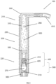
- FIG 1 shows a schematic longitudinal section of an exemplary embodiment of a device 100 for applying a pharmaceutical fluid (in figure 1 Not shown).
- the device 100 comprises a hollow cylindrical body 200 with a proximal body end 210 and a proximal body end 210 axially opposite distal body end 220.
- An outer surface of the body 200 is formed as an external thread 230.
- the external thread 230 extends over almost the entire length of the device 100.
- the external thread 230 does not extend over almost the entire length, but for example only over 50% of the entire length Length of the device 100.
- the external thread 230 is used to screw the device 100 into a drilled hole in a patient's bone.
- a fluid-conducting channel 250 runs axially through the hollow-cylindrical body 200, the channel 250 extending from a proximal end of the body 210 facing the proximal end Channel end 260 extends through the entire body 200 to a body distal end 220 facing distal channel end 270 .
- the proximal end of the channel 260 is fluidly connected to a connecting element 300, via which the device 100 can be connected to a reservoir for a pharmaceutical fluid (both not shown in figure 1 ) is fluidly connectable.
- the connecting element 300 has a connecting element section 310 which is inserted into the proximal channel end 260 .
- the connecting element 300 is formed as a grommet, so that a reservoir for a pharmaceutical fluid can be connected in a fluid-conducting manner to the device 100 by means of a tube 610 (shown only in sections).
- a check valve 400 in the form of a ball check valve comprising a ball 410 and a restoring element 420 in the form of four elastic elements shaped like leaf springs is arranged in channel 250 (only three of the elements are shown, the fourth is outside the plane of the drawing).
- the restoring element 420 exerts a force on the ball 410 so that it closes the check valve 400 in a fluid-conducting manner.
- the check valve 400 is arranged such that a fluid coming from the direction of the proximal channel end 260 can move the ball 410 against the force of the restoring element 420 in the direction of the distal channel end 270, so that the check valve 400 is opened in a fluid-conducting manner.
- the non-return valve 400 remains closed in a fluid-conducting manner and cannot be opened without being destroyed.
- a sealing element 500 is arranged within the channel 250, comprising a gap 510 that is closed in a fluid-conducting manner.
- the restoring element 420 and the sealing element 500 are designed in one piece.
- a sleeve 360 is arranged distally to the sealing element 500, which has a tongue and groove connection 365 with the body 200 is fixed in channel 250.
- a filter element 350 in the form of a microporous filter plate is arranged in the channel 250 proximal to the check valve 400 in order to clean a pharmaceutical fluid conveyed through the device 100 of microorganisms.
- the duct 250 has a duct constriction 255, so that the filter element 350, the check valve 400 and the sealing element 500 are fixed between the sleeve 360 and the duct constriction 255.
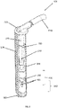
- FIG figure 2 10 shows the device 100.
- FIG figure 1 in a perspective side view of a partial schematic longitudinal section.
- the perspective of the device 100 shown in the illustration shows that the connecting element section 310 and the proximal channel end 260 are polygonal, in particular hexagonal, so that the connecting element section 310 can be inserted into the proximal channel end 260 in a reversible, non-twisting manner.
- the polygonal proximal channel end 260 has a greater axial extension than the polygonal connecting element section 310 . This allows the proximal end of the channel 260 to be shortened, for example by sawing or cutting it off, and a fluid-conducting connection of the connecting element section 310 to the remainder of the proximal end of the channel 260 after shortening which would have been of insufficient thickness prior to trimming.
- FIG 3 shows the device 100 of FIGS figures 1 and 2 , wherein a pharmaceutical fluid 650 has been introduced into the proximal end of the channel 260 via the tube 610 .
- Pharmaceutical fluid 650 fills channel 250 from proximal end 260 to ball 410 .
- a conveying pressure must be built up on the pharmaceutical fluid 650, which at least overcomes the force of the return element 420 acting on the ball 40 and thus opens the check valve 400 in a fluid-conducting manner.
- FIG 4 shows the device 100 of FIGS Figures 1 to 3 , wherein a sufficiently high delivery pressure 660 (symbolized as an arrow) is exerted on the pharmaceutical fluid 650 from the direction of the proximal channel end 260 in order to push the ball 410 against the restoring force of the To move return element 420 in the direction of the distal end 270 of the channel.
- the restoring element 420 is reversibly deformed and the check valve 400 is open to conduct fluid.
- the delivery pressure 660 is sufficiently high to also open the gap 510 of the sealing element 500 in a fluid-conducting manner in a reversible manner. This allows the pharmaceutical fluid 650 to be applied from the distal end of the channel 270.
- the application of the pharmaceutical fluid 650 stops within a few moments, for example within a second or less.
- FIG. 5 shows the device 100 of FIGS Figures 1 to 4 fluidly connected to a reservoir 600 for a pharmaceutical fluid 650 in the form of a syringe.
- the device 100 is connected to the reservoir 600 in a fluid-conducting manner via a tube 610 and an adapter 620 in the form of a Luer system.
- a delivery pressure 660 can be built up on the pharmaceutical fluid 650 and this can be applied to a desired location by the device 100 .
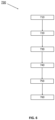
- FIG. 6 shows a flowchart of a method for applying a pharmaceutical fluid 650 by means of device 100, comprising steps 710 to 760.
- Device 100 comprises hollow-cylindrical body 200, which surrounds channel 250, which extends from proximal body end 210 to distal body end 220 of body 200 extends through the body 200, the outer surface of the body 200 at least partially having the external thread 230, the connecting element 300 arranged at the proximal end of the body 210 can be reversibly connected to a reservoir 600 for the pharmaceutical fluid 650 via the proximal channel end 260 of the channel 250, wherein the check valve 400 arranged in the channel 250, which is designed to be fluid-impermeable in the direction of the proximal end of the channel 260, and the sealing element 500 arranged in the channel 250 distally to the check valve 400, which closes the distal end of the channel 270 of the channel 250 in a fluid-conducting manner and when pressure is applied Position 660 on the pharmaceutical fluid 650 from
- the device 100 is implanted, in particular in a bone tissue of a patient in the spatial vicinity of a joint, for example in a condyle of a corresponding bone.
- step 720 the device 100 is fluidly connected to a reservoir 600 for the pharmaceutical fluid 650 .
- This can be done via a hose 610, for example.
- the fluid-conducting connection 720 can already take place before or only after the implantation has taken place in step 710, with preference being given to after the implantation has taken place.
- a delivery pressure 660 of at least 5 N/cm 2 is built up on the pharmaceutical fluid 650 from the direction of the proximal channel end 260 .
- This feed pressure 660 is sufficient to open the check valve 400 and the sealing element 500, in particular the gap 510 in the sealing element 500, in a fluid-conducting manner. If the delivery pressure 660 is less than 5 N/cm 2 , at least the gap 510 in the sealing element 500 remains closed in terms of fluid conduction and the pharmaceutical fluid 650 is not discharged from the device 100, in particular the distal channel end 270 of the device 100.
- This limit value of the delivery pressure 660 ensures that there is no unintentional and uncontrolled application of the pharmaceutical fluid 610 from the device 100, which could have negative effects on the patient.
- step 750 the pharmaceutical fluid 650 is discharged from the same.
- the pharmaceutical fluid 650 continues to be discharged as long as the delivery pressure 660 is above the limit value of 5 N/cm 2 or the pharmaceutical fluid 650 is completely discharged.
- step 760 the delivery pressure 660 is lowered below the limit value of 5 N/cm 2 , as a result of which at least the gap 510 automatically closes again in a fluid-conducting manner and the application of the pharmaceutical fluid 650 is terminated.
- the method 700 can be performed any number of times.
Landscapes
- Health & Medical Sciences (AREA)
- Life Sciences & Earth Sciences (AREA)
- Surgery (AREA)
- Heart & Thoracic Surgery (AREA)
- Animal Behavior & Ethology (AREA)
- Veterinary Medicine (AREA)
- Public Health (AREA)
- Engineering & Computer Science (AREA)
- Biomedical Technology (AREA)
- General Health & Medical Sciences (AREA)
- Molecular Biology (AREA)
- Nuclear Medicine, Radiotherapy & Molecular Imaging (AREA)
- Medical Informatics (AREA)
- Orthopedic Medicine & Surgery (AREA)
- Physics & Mathematics (AREA)
- Pathology (AREA)
- Radiology & Medical Imaging (AREA)
- Optics & Photonics (AREA)
- Biophysics (AREA)
- Fluid Mechanics (AREA)
- Pulmonology (AREA)
- Anesthesiology (AREA)
- Hematology (AREA)
- Prostheses (AREA)
Abstract
Description
- Die Erfindung betrifft eine Vorrichtung zur Applikation eines pharmazeutischen Fluids umfassend einen hohlzylinderförmigen Körper, der einen Kanal umgibt, der sich von einem proximalen Körperende zu einem distalen Körperende des Körpers durch den Körper erstreckt, wobei eine Außenfläche des Körpers zumindest teilweise ein Außengewinde aufweist, und ein am proximalen Körperende angeordnetes Verbindungselement, über das ein proximales Kanalende des Kanals fluidleitend mit einem Reservoir für das pharmazeutische Fluid reversibel verbindbar ist.
Die Erfindung betrifft weiterhin ein Verfahren zur Applikation eines pharmazeutischen Fluids mittels einer derartigen Vorrichtung. - Gegenstand der Erfindung ist insbesondere eine medizinische Vorrichtung zur temporären, lokalen Applikation von pharmazeutischen Fluiden oder anderen medizinischen Fluiden über einen Zeitraum von Stunden bis zu mehreren Monaten. Die erfindungsgemäße Vorrichtung ist vor allem für die Behandlung entzündlicher Erkrankungen von Gelenken, wie die aktivierte Arthrose und die rheumatische Arthritis, bestimmt.
- Entzündliche Erkrankungen der Gelenke, wie die aktivierte Arthrose und die rheumatische Arthritis, sind weit verbreitet. Diese Erkrankungen sind häufig mit Gelenkschmerzen verbunden und können durch einen fortschreitenden Entzündungsprozess eine zunehmende Gelenkzerstörung bewirken, welche zu einer Beeinträchtigung der Gelenkfunktion oder gar zu einem vollständigen Verlust der Gelenkfunktion führen können.
- Neben einer systemischen pharmakologischen Therapieoption, welche mit Nebenwirkungen für den Patienten behaftet sein kann und welche aufgrund einer vergleichsweise geringen Wirkstoffkonzentration an der Entzündungsstelle weniger wirksam ist, gibt es die Möglichkeit, durch intraartikuläre Injektion von pharmazeutischen Fluiden, insbesondere von entzündungshemmenden Wirkstoffen, den Entzündungsprozess zu beeinflussen. Als Wirkstoffe kommen hierbei beispielsweise Dexamethasonphosphat, Cyclosporin, Sulfasalazin und Methotrexat in Betracht.
- Kritisch ist bei der intraartikulären Injektion zu sehen, dass eine nicht unerhebliche Infektionsgefahr für den intraartikulären Raum besteht. Weiterhin sind die Gelenkkapseln des Menschen mit Nozizeptoren ausgestattet, wodurch die Gelenkkapsel sehr schmerzempfindlich sind.
- Knochenschrauben mit einem zentralen Kanal im Schraubenkörper und damit verbundenen Austrittsöffnungen sind unter der Bezeichnung kanülierte und fenestrierte Schrauben bekannt. Bisher werden diese Knochenschrauben im Wesentlichen im Spine-Bereich als sogenannte kanülierte und fenestrierte Pedikelschrauben eingesetzt. Dabei wird durch den Kanal der Schrauben Knochenzementteig in den meist osteoporotischen Wirbelkörper eingespritzt, wodurch sich überwiegend ein zur Längsachse der Pedikelschraube koaxialer Zementmantel ausbildet. Der Knochenzement härtet anschließend aus und bildet ein Widerlager für die Pedikelschrauben. Eine Vielzahl von kanülierten und fenestrierten Knochenschrauben wurden vorgeschlagen. Exemplarisch sind dafür die Patenschriften und Offenlegungsschriften
DE 35 08 759 A1 ,DE 1994 9285 C2 ,DE 10 2011 112 890 B4 ,EP 1 210 019 B1 ,EP 2 887 899 B1 genannt. - Daneben können kanülierte und fenestrierte Knochenschrauben auch zur lokalen Applikation pharmazeutischer Fluide eingesetzt werden, wie dies exemplarisch in den Patentschriften und Offenlegungsschriften
US 9 616 205 B2 US 10 357 298 B2 US 2018/0014867 A1 beschrieben wurde. - Nachteilig an den bisher beschriebenen kanülierten und fenestrierten Knochenschrauben gestaltet sich ein Einwachsen von Gewebe, insbesondere von Bindegewebe, in die Austragsöffnungen der Knochenschrauben, welches ein weiteres Applizieren pharmazeutischer Fluide mittels der derart fluidleitend verschlossenen Knochenschraube erschwert oder gar vollständig unterbindet.
- Wünschenswert ist daher eine Vorrichtung, die gegen ein Einwachsen von Gewebe, insbesondere von Bindegewebe, geschützt ist, so dass eine Applikation eines pharmazeutischen Fluids über einen längeren Zeitraum, beispielsweise über mehrere Wochen oder gar Monate, möglich ist. Weiterhin sollte die Vorrichtung eine lokale Applikation beliebiger pharmazeutischer Wirkstoffe in Form pharmazeutischer Fluide zulassen, wobei es jederzeit möglich ist, die Zusammensetzung und/oder die Konzentration an Wirkstoffen in dem pharmazeutischen Fluid auszutauschen. Außerdem ist es wünschenswert, dass die Wirkstoffkonzentration im pharmazeutischen Fluid, die unmittelbar am Implantationsort der Vorrichtung erreicht wird, direkt von außen eingestellt werden kann.
- Eine Aufgabe der vorliegenden Erfindung ist es, einen oder mehrere der sich aus dem Stand der Technik ergebenen Nachteile zumindest teilweise zu überwinden.
- Insbesondere soll eine Vorrichtung zur lokalen Applikation pharmazeutischer Fluide, wie zum Beispiel von antiphlogistische, cytostatische und glucocorticoidische Lösungen, bereitgestellt werden, mit der eine lokale und temporäre Abgabe des pharmazeutischen Fluids in Gelenkkapseln eines Patienten, insbesondere Gelenkkapseln größerer Gelenke wie beispielsweise dem Kniegelenk, ermöglicht wird.
- Die Vorrichtung soll so beschaffen sein, dass von außerhalb des Patientenkörpers dem Patienten bei Bedarf pharmazeutische Fluide beliebiger und wechselnder Zusammensetzung mehrfach in eine Gelenkkapsel eingebracht werden können, ohne dass dabei die Gelenkkapsel durchstochen werden muss. Die Vorrichtung soll auch über längere Zeiträume, beispielsweise über einen Zeitraum von mehreren Wochen oder mehreren Monaten im Patienten zur wiederholten Abgabe des pharmazeutischen Fluids geeignet sein, ohne dass die Vorrichtung hierfür entfernt werden muss und ohne dass es zu einem Verstopfen der Vorrichtung, insbesondere durch Ablagerung körpereigenem Gewebes, insbesondere körpereigener Proteine, kommt. Weiterhin soll Synovialflüssigkeit nicht durch die Vorrichtung aus der Gelenkkapsel austreten. Die Vorrichtung soll durch ihren Aufbau verhindern, dass Mikroorganismen in den intraartikulären Raum eindringen können. Die Vorrichtung soll kostengünstig zu fertigen sein und möglichst ein hygienisches, nur einmal verwendbares Wegwerfprodukt sein. Die Fluidabgabe aus der Vorrichtung soll von außen kontrolliert werden können.
- Es ist eine weitere Aufgabe der Erfindung, ein Verfahren bereitzustellen, mit dem eine lokal begrenzte Applikation pharmazeutischer Fluide möglich ist, mittels dem mindestens ein Teil der bereits beschriebenen Aufgaben zumindest zum Teil gelöst wird.
- Ein Beitrag zur mindestens teilweisen Erfüllung mindestens einer der zuvor genannten Aufgaben wird durch die Merkmale der unabhängigen Ansprüche geleistet. Die abhängigen Ansprüche stellen bevorzugte Ausführungsformen bereit, die zur mindestens teilweisen Erfüllung mindestens einer der Aufgaben beitragen.
- Eine erste Ausführungsform der Erfindung ist eine Vorrichtung zur Applikation eines pharmazeutischen Fluids umfassend einen hohlzylinderförmigen Körper, der einen Kanal umgibt, der sich von einem proximalen Körperende zu einem distalen Körperende des Körpers durch den Körper erstreckt, wobei eine Außenfläche des Körpers zumindest teilweise ein Außengewinde aufweist, ein am proximalen Körperende angeordnetes Verbindungselement, über das ein proximales Kanalende des Kanals reversibel fluidleitend mit einem Reservoir für das pharmazeutische Fluid verbindbar ist, gekennzeichnet durch ein im Kanal angeordnetes Rückschlagventil, welches in Richtung des proximalen Kanalendes fluidundurchlässig ausgestaltet ist, und ein im Kanal distal zum Rückschlagventil angeordnetes Dichtungselement, welches ein distales Kanalende des Kanals fluidleitend verschließt und welches einen Spalt aufweist, welcher bei einer Druckbeaufschlagung auf das pharmazeutische Fluid aus Richtung des proximalen Kanalendes reversibel fluidleitend öffenbar ist, so dass das pharmazeutische Fluid aus dem distalen Kanalende applizierbar ist.
- In einer Ausführungsform der Vorrichtung öffnet sich der Spalt bei einer Druckbeaufschlagung von größer als 5 N/cm2, bevorzugt größer als 6 N/cm2, weiter bevorzugt größer als 7 N/cm2, reversibel fluidleitend, so dass das distale Kanalende fluidleitend geöffnet ist. Diese Ausführungsform ist eine zweite Ausführungsform der Erfindung, welche vorzugsweise von der ersten Ausführungsform der Erfindung abhängt.
- In einer Ausführungsform der Vorrichtung umfasst, insbesondere ist, das Rückschlagventil ein Kugelrückschlagventil umfassend eine Kugel und ein Rückstellelement. Diese Ausführungsform ist eine dritte Ausführungsform der Erfindung, welche vorzugsweise von der ersten oder zweiten Ausführungsform der Erfindung abhängt.
- In einer Ausführungsform der Vorrichtung sind das Rückstellelement und das Dichtungselement einteilig ausgestaltet. Diese Ausführungsform ist eine vierte Ausführungsform der Erfindung, welche vorzugsweise von der dritten Ausführungsform der Erfindung abhängt.
- In einer Ausführungsform der Vorrichtung ist im Kanal ein Filterelement angeordnet. Diese Ausführungsform ist eine fünfte Ausführungsform der Erfindung, welche vorzugsweise von einer der vorhergehenden Ausführungsformen der Erfindung abhängt.
- In einer Ausführungsform der Vorrichtung ist das Filterelement im Kanal proximal zum Rückschlagventil, also näher am proximalen Kanalende als das Rückschlagventil, angeordnet. Diese Ausführungsform ist eine sechste Ausführungsform der Erfindung, welche vorzugsweise von der fünften Ausführungsform der Erfindung abhängt.
- In einer Ausführungsform der Vorrichtung ist das Filterelement eine mikroporöse Filterplatte. Diese Ausführungsform ist eine siebte Ausführungsform der Erfindung, welche vorzugsweise von der fünften oder der sechsten Ausführungsform der Erfindung abhängt.
- In einer Ausführungsform der Vorrichtung weist die mikroporöse Filterplatte Poren mit einem durchschnittlichen Porendurchmesser von kleiner 40 µm, bevorzugt von kleiner 5 µm, weiter bevorzugt von kleiner 1 µm, auf. Diese Ausführungsform ist eine achte Ausführungsform der Erfindung, welche vorzugsweise von der siebten Ausführungsform der Erfindung abhängt.
- In einer Ausführungsform der Vorrichtung ist im Kanal distal zum Dichtungselement, also näher am distalen Kanalende als das Dichtungselement, eine hohlzylinderförmige Hülse angeordnet, um ein Austragen des Dichtungselements, und damit bevorzugt auch aller weiterenn Strukturelemente im Kanal proximal zum Dichtungselement, aus dem distalen Kanalende beim Applizieren des pharmazeutischen Fluids zu unterbinden. Diese Ausführungsform ist eine neunte Ausführungsform der Erfindung, welche vorzugsweise von einer der vorhergehenden Ausführungsformen der Erfindung abhängt.
- In einer Ausführungsform der Vorrichtung ist das proximale Kanalende mehrkantförmig, insbesondere sechskantförmig, ausgebildet und das Verbindungselement mit einem dazu passenden mehrkantförmigen, insbesondere sechskantförmigen, Verbindungselementabschnitt ausgestattet, um das Verbindungselement mit dem proximalen Kanalende reversibel fluidleitend durch Einstecken des Verbindungselementabschnitts in das proximale Kanalende zu verbinden.
- Diese Ausführungsform ist eine zehnte Ausführungsform der Erfindung, welche vorzugsweise von einer der vorhergehenden Ausführungsformen der Erfindung abhängt.
- In einer Ausführungsform der Vorrichtung weist das mehrkantförmige, insbesondere sechskantförmige, proximale Kanalende eine größere axiale Erstreckung auf als der mehrkantförmige, insbesondere sechskantförmige Verbindungselementabschnitt, so dass nach einem Entfernen, insbesondere durch Abschneiden oder Absägen, eines Teils, insbesondere eines proximalen Teils des proximalen Kanalendes, das Verbindungselement mit einem an der Vorrichtung verbleibenden Teil des proximalen Kanalendes reversibel fluidleitend durch Einstecken des Verbindungselementabschnitts in das verbleibende proximale Kanalende verbindbar ist. Diese Ausführungsform ist eine elfte Ausführungsform der Erfindung, welche vorzugsweise von der zehnten Ausführungsform der Erfindung abhängt.
- In einer Ausführungsform der Vorrichtung umfasst der Körper ein Metall, ein Polymer oder ein Metall und ein Polymer, insbesondere besteht der Körper aus einem Metall, einem Polymer oder einem Metall und einem Polymer. Diese Ausführungsform ist eine zwölfte Ausführungsform der Erfindung, welche vorzugsweise von einer der vorhergehenden Ausführungsformen der Erfindung abhängt.
- Eine dreizehnte Ausführungsform der Erfindung ist ein Verfahren zur Applikation eines pharmazeutischen Fluid mittels einer Vorrichtung nach einer der ersten bis zwölften Ausführungsform der Erfindung aufweisend die folgenden Schritte:
- a. Implantieren der Vorrichtung in;
- b. Fluidleitendes Verbinden der Vorrichtung mit einem Reservoir für das pharmazeutischen Fluids;
- c. Aufbau eines Förderdrucks auf das pharmazeutische Fluid aus Richtung des proximalen Kanalendes von größer 5 N/cm2;
- d. Fluidleitendes Öffnen des Spalts im Dichtungselements durch Einwirkung des Förderdrucks;
- e. Ausbringen des pharmazeutischen Fluids aus dem fluidleitend geöffneten Spalt;
- f. Fluidleitendes Verschließen des Spalts durch Reduktion des Förderdrucks auf 5 N/cm2 oder weniger.
- In der vorliegenden Beschreibung beinhalten Bereichsangaben auch die als Grenzen genannten Werte. Eine Angabe der Art "im Bereich von X bis Y" in Bezug auf eine Größe A bedeutet folglich, dass A die Werte X, Y und Werte zwischen X und Y annehmen kann. Einseitig begrenzte Bereiche der Art "bis zu Y" für eine Größe A bedeuten entsprechend als Wert Y und kleiner als Y.
- Einige der beschriebenen Merkmale sind mit dem Begriff "im Wesentlichen" verknüpft. Der Begriff "im Wesentlichen" ist so zu verstehen, dass unter realen Bedingungen und Fertigungstechniken eine mathematisch exakte Auslegung von Begrifflichkeiten wie "Überlagerung", "senkrecht", "Durchmesser" oder "Parallelität" nie exakt, sondern nur innerhalb gewisser fertigungstechnischer Fehlertoleranzen gegeben sein kann. Beispielsweise schließen "im Wesentlichen senkrechte Achsen" einen Winkel von 85 Grad bis 95 Grad zueinander ein und "im Wesentlichen gleiche Volumen" umfassen eine Abweichung von bis zu 5 Volumen-%. Eine "im Wesentlichen aus Kunststoff bestehende Vorrichtung" umfasst beispielsweise einen Kunststoffanteil von ≥95 bis ≤100 Gewichts-%. Eine "im Wesentlichen vollständige Befüllung eines Volumens B" umfasst beispielsweise eine Befüllung von ≥95 bis ≤100 Volumen-% des Gesamtvolumens von B.
- Ein erster Gegenstand der Erfindung betrifft eine Vorrichtung zur Applikation eines pharmazeutischen Fluids, insbesondere zur Applikation eines pharmazeutischen Fluids in eine Gelenkkapsel, umfassend einen hohlzylinderförmigen Körper, der einen Kanal umgibt, der sich von einem proximalen Körperende zu einem distalen Körperende des Körpers durch den Körper erstreckt,
wobei eine Außenfläche des Körpers zumindest teilweise ein Außengewinde aufweist,
ein am proximalen Körperende angeordnetes Verbindungselement, über das ein proximales Kanalende des Kanals reversibel fluidleitend mit einem Reservoir für das pharmazeutische Fluid verbindbar ist,
gekennzeichnet durch
ein im Kanal angeordnetes Rückschlagventil, welches in Richtung des proximalen Kanalendes fluidundurchlässig ausgestaltet ist, und ein im Kanal distal zum Rückschlagventil angeordnetes Dichtungselement, welches ein distales Kanalende des Kanals fluidleitend verschließt und in dem bei einer Druckbeaufschlagung auf das pharmazeutische Fluid aus Richtung des proximalen Kanalendes reversibel ein Spalt fluidleitend öffenbar ist, so dass das pharmazeutische Fluid aus dem distalen Kanalende applizierbar ist. - Die Vorrichtung weist im Kanal ein Rückschlagventil auf. Ein Rückschlagventil ist ein Bauteil, welches ein Fördern des pharmazeutischen Fluids in eine Förderrichtung erlaubt, während ein Fördern in die entgegengesetzte Förderrichtung unterbunden wird. Das erfindungsgemäße Rückschlagventil erlaubt ein Fördern des pharmazeutischen Fluids aus Richtung des proximalen Kanalendes in Richtung des distalen Kanalendes, während ein Fördern des pharmazeutischen Fluids aus Richtung des distalen Kanalendes in Richtung des proximalen Kanalendes unterbunden ist. Das erfindungsgemäße Rückschlagventil ist also in Richtung des distalen Kanalendes fluidleitend und in Richtung des proximalen Kanalendes fluidundurchlässig ausgestaltet. Dies erlaubt somit ein Fördern und Applizieren eines pharmazeutischen Fluids aus einem mit dem Verbindungselement verbundenen Reservoir für das pharmazeutische Fluid durch die Vorrichtung und aus dem distalen Kanalende heraus, während ein Eindringen von Fluiden, insbesondere mit Bindegewebe versetzten Fluiden, in den Kanal proximal des Rückschlagventils verhindert wird. Dies verhindert eine, insbesondere vollständige, Kontamination und/oder Verstopfung der Vorrichtung und des mit der Vorrichtung verbundenen Reservoirs durch ein in das distale Kanalende eindringendes Fluid, wie beispielsweise Blut.
- Distal zum Rückschlagventil, also näher am distalen Kanalende als das Rückschlagventil, ist im Kanal ein Dichtungselement angeordnet, welches das distale Kanalende solange fluidleitend verschließt, bis sich, ausgelöst durch eine ausreichend hohe Druckbeaufschlagung auf das im Kanal befindliche pharmazeutische Fluid aus Richtung des proximalen Kanalendes, ein Spalt im Dichtungselement fluidleitend öffnet. Ist die Druckbeaufschlagung nicht hoch genug, bleibt der Spalt fluidleitend verschlossen. Das pharmazeutische Fluids kann bei fortgesetzter Druckbeaufschlagung durch den fluidleitend geöffneten Spalt aus dem Kanal an eine gewünschte Stelle appliziert werden. Mit Beendigung der Druckbeaufschlagung schließt sich der zuvor ausgebildete fluidleitend geöffnete Spalt im Dichtungselement selbstständig wieder innerhalb weniger Augenblicke, beispielsweise innerhalb von Bruchteilen einer Sekunde, und das distale Kanalende ist wieder fluidleitend durch das Dichtungselement verschlossen. Dazu ist das Dichtungselement vorzugsweise aus einem elastischen Material ausgestaltet. Durch das Dichtungselement ist ein Einwachsen von Bindegewebe und ein Eindringen von Blut in die Vorrichtung unterbunden, weshalb die Vorrichtung funktionsfähig über mehrere Tage bis Monate im Patientenkörper implantiert sein kann und dabei eine wiederholte lokale Applikation eines pharmazeutischen Fluids an der gewünschten Stelle im Patienten ermöglicht ist. Ein weiterer Vorteil des Aufbaus der Vorrichtung ist, dass, selbst falls das distale Kanalende, beispielsweise durch Bindegewebe oder geronnenes Blut, fluidleitend verstopft sein sollte, diese Verstopfung durch die Druckbeaufschlagung und die darauffolgende Ausbringung des pharmazeutischen Fluids aus der Vorrichtung unter Druck beseitigt würde. Der Aufbau und die Funktionsweise der Vorrichtung ermöglicht somit eine "Selbstreinigung" der Verstopfung durch Gebrauch der Vorrichtung.
- Das Dichtungselement kann dazu einen oder mehr als einen Spalt aufweisen, wobei der eine oder mehr als eine Spalt verschiedene Formen aufweisen kann. Aufgrund der einfachen Herstellungsweise ist ein einzelner, länglich ausgeformter Spalt bevorzugt.
- Dabei kann die Vorrichtung auf zumindest zwei Arten betrieben werden. In einer ersten Art wird die Druckbeaufschlagung pulsartig ausgeführt, so dass bereits durch ein Applizieren einer kleinen Menge an pharmazeutischem Fluid, beispielsweise bis zu 2 Milliliter, aus der Vorrichtung heraus ein durch die Druckbeaufschlagung erzeugter Innendruck derart abnimmt, dass der Spalt wieder fluidleitend geschlossen wird. Dabei erreicht die Druckbeaufschlagung nur kurzfristig, also pulsartig, einen benötigten Grenzwert, um den Spalt reversibel fluidleitend auszuformen. In einer weiteren Art erfolgt eine kontinuierliche Druckbeaufschlagung auf das pharmazeutische Fluid, so dass dieses so lange aus dem distalen Kanalende austragbar ist, solange die Druckbeaufschlagung mit dem benötigten Grenzwert aufrechterhalten wird. Diese Art der Druckbeaufschlagung erlaubt somit eine kontinuierliche Applikation eines pharmazeutischen Fluids.
- Sollte trotz des Dichtungselements mit Bindegewebe versetztes Fluid in das distale Kanalende eindringen, dient das Rückschlagventil als eine zweite Barriere für das eindringende Fluid. Dichtungselement und Rückschlagventil wirken also synergistisch zusammen, so dass eine Kontamination der Vorrichtung effektiv unterbunden wird. Dies erlaubt eine Implantation der Vorrichtung über einen im Vergleich zu einer Vorrichtung mit lediglich einer Barriere verlängerten Zeitraum.
- Das Rückschlagventil kann unterschiedliche Bauformen aufweisen. In einer Ausgestaltungsform umfasst das Rückschlagventil eine Rückschlagklappe, welche ein Fördern des pharmazeutischen Fluids durch den Kanal nur in eine Förderrichtung erlaubt und in die entgegengesetzte Förderrichtung den Kanal fluidleitend verschließt.
- Die Vorrichtung umfasst einen hohlzylinderförmigen Körper. Unter einem hohlzylinderförmigen Körper ist ein rohrartiges Strukturelement zu verstehen, welches einen Kanal mit einer dem Kanal zugewandten Innenfläche und einer dem Kanal abgewandten Außenfläche umgibt. Der Querschnitt des Körpers kann beliebige Formen annehmen. Aufgrund der einfachen Fertigung und der besseren Verankerungsmöglichkeit innerhalb eines Patienten ist der Querschnitt, und bevorzugt auch der Querschnitt des Kanals, im Wesentlichen kreisförmig ausgestaltet.
- Der Kanal verläuft dabei von einem proximalen Körperende des Körpers durch den Körper bis zu einem distalen Körperende des Körpers. Dabei ist ein proximales Kanalende des Kanals dem proximalen Körperende und ein distales Kanalende des Kanals dem distalen Körperende zugewandt.
- "Proximal" und "distal" dienen dabei lediglich der Bezeichnung der räumlich entgegengesetzten Enden der Vorrichtung, des Körpers oder anderer Struktureinheiten der Vorrichtung und erlauben keinen Rückschluss auf die Orientierung der in einen menschlichen Körper implantieren Vorrichtung. "Distal zu ..." und "proximal zu..." oder ähnliche Formulierungen drücken entsprechend lediglich die räumliche Anordnung zweier Struktureinheiten der Vorrichtung zueinander aus.
- Die Außenfläche des Körpers weist zumindest abschnittsweise ein Außengewinde auf. Das Außengewinde dient der Verankerung der Vorrichtung in einem Gewebe, insbesondere einem Knochengewebe eines Patienten, durch Einschrauben der Vorrichtung in ein entsprechendes vorbereitetes Bohrloch im Gewebe, insbesondere im Knochengewebe. In einer Ausgestaltungsform erstreckt sich das Außengewinde über die gesamte axiale Erstreckung des Körpers, so dass der Körper über seine gesamte Länge in das entsprechende Bohrloch eingeschraubt werden kann. Das Außengewinde kann dabei auf einer Außenseite eines rohrartigen Elements angeordnet sein, welches den Körper manschettenartig umgibt. In einer bevorzugten Ausgestaltungsform ist die Außenfläche des Körpers selbst als Außengewinde ausgeformt.
- Die Vorrichtung weist am proximalen Körperende ein fluidleitendes Verbindungselement auf, über das das proximale Kanalende reversibel fluidleitend mit einem Reservoir für das pharmazeutische Fluid verbindbar ist. In einer Ausgestaltungsform sind das Verbindungselement und das proximale Körperende einteilig ausgestaltet. In weiteren, bevorzugten Ausgestaltungsformen sind das Verbindungselement und das distale Körperende reversibel miteinander fluidleitend verbindbar ausgestaltet. Das Verbindungselement kann auf unterschiedliche Weise ausgestaltet sein, um das proximale Kanalende fluidleitend mit einem Reservoir für ein pharmazeutisches Fluid zu verbinden. In einer Ausgestaltungsform ist das Verbindungselement als Tülle ausgeformt, über die das proximale Kanalende mittels eines Schlauchs mit einem Reservoir fluidleitend verbindbar ist. In einer weiteren Ausgestaltungsform ist das Verbindungselement als Gewinde ausgeformt, welches über ein entsprechendes Gegenstück fluidleitend mit einem Reservoir verbindbar ist. In einer weiteren Ausgestaltungsform formt das Verbindungselement mit einem Reservoir eine Flanschverbindung. In einer weiteren Ausgestaltungsform formt das Verbindungselement über eine Schlauchkupplung mit einem Reservoir eine fluidleitende Verbindung, wobei das Verbindungselement die Kupplung oder den Nippel der Schlauchkupplung aufweisen kann.
- Unter einem Reservoir werden alle Behältnisse verstanden, welche dazu geeignet sind, ein pharmazeutische Fluid zu lagern. Beispiele für Reservoire umfassen Beutel, Spritzen, Kolben, Ballons, Kanister und Ampullen, wobei Beutel, Ballons und Spritzen bevorzugt sind.
- Die erfindungsgemäße Vorrichtung dient zur lokalen Applikation eines pharmazeutischen Fluids, insbesondere zur Behandlung entzündlicher Erkrankungen von Gelenken, wie die aktivierte Arthrose und die rheumatische Arthritis, über einen Zeitraum von mehreren Tagen bis mehreren Monaten. Ein pharmazeutisches Fluid enthält wenigstens einen pharmazeutischen Wirkstoff. Beispielsweise handelt es sich bei dem pharmazeutischen Fluid um wässrige oder nicht-wässrige Lösungen oder Suspensionen von pharmazeutischen Wirkstoffen.
In einer Ausgestaltungsform handelts es sich bei dem pharmazeutisches Fluid um Lösungen, welche wenigstens ein Antiphlogistikum, Cytostatikum und/oder Glucocorticoid enthalten. In einer weiteren Ausgestaltungsform enthalten die pharmazeutischen Fluide wenigstens einen desinfizierenden Bestandteil.
Weiterhin umfassen pharmazeutische Fluide auch Gase, Gasgemische und Lösungen von Gasen in Flüssigkeiten, wie beispielsweise Wasser. - Die zur Ausbildung des fluidleitend geöffneten Spalts im Dichtungselement benötigte Druckbeaufschlagung auf das pharmazeutische Fluid kann von unterschiedlichen Faktoren, wie beispielsweise dem Material des Dichtungselements, dem Durchmesser des Dichtungselements und der Länge des Dichtungselements abhängen.
- Um ein kontrolliertes Applizieren des pharmazeutischen Fluids aus der Vorrichtung zu gewähren, ist eine Ausführungsform der Vorrichtung dadurch gekennzeichnet, dass sich der Spalt erst ab einer Druckbeaufschlagung von mindestens 5 N/cm2 auf das pharmazeutische Fluid aus Richtung des proximalen Kanalendes reversibel fluidleitend im Dichtungselement öffnet, so dass das distale Kanalende fluidleitend geöffnet ist. Erreicht die Druckbeaufschlagung nicht diesen Grenzwert, bleibt der Spalt und damit das distale Kanalende fluidleitend verschlossen. Dies verhindert ein unbeabsichtigtes Austreten des pharmazeutischen Fluids aus der Vorrichtung in den Patienten, welches gesundheitliche Risiken nach sich ziehen könnte. Ein weiterer Vorteil ist, dass somit auch ein Eindringen von mit Gewebe, insbesondere mit Bindegewebe, versetzten Fluiden des Patienten nicht ohne Erreichen eines entsprechend entgegengesetzten Förderdrucks in Richtung des proximalen Kanalendes in die Vorrichtung durch das distale Kanalende zumindest erschwert ist. Ein Eindringen dieser körpereigener Fluide könnte eine Kontamination der Vorrichtung oder ein Verstopfen der Vorrichtung nach sich ziehen. Damit ein Applizieren kontrolliert, auch in kleinen Mengen und ohne das Risiko einer unbeabsichtigten Zerstörung in der Vorrichtung, wie beispielsweise einer Rissbildung im Körper oder im Dichtungselement, stattfinden kann, ist es bevorzugt, dass zur fluidleitenden Öffnung des Spalts die Druckbeaufschlagung nicht mehr als 150 N/cm2 betragen muss.
- Das Rückschlagventil kann unterschiedliche Bauformen aufweisen. In einer Ausgestaltungsform umfasst das Rückschlagventil eine Rückschlagklappe, welche ein Fördern des pharmazeutischen Fluids durch den Kanal in nur eine Förderrichtung, insbesondere in Richtung des distalen Kanalendes, erlaubt und in die entgegengesetzte Förderrichtung, insbesondere in Richtung des proximalen Kanalendes, den Kanal fluidleitend verschließt. In einer weiteren Ausgestaltungsform ist das Rückschlagventil als Tellerrückschlagventil ausgebildet.
- Eine Ausführungsform der Vorrichtung ist dadurch gekennzeichnet, dass das Rückschlagventil ein Kugelrückschlagventil umfassend eine Kugel und ein Rückstellelement ist. Bei einem Kugelrückschlagventil wird ein Leitungsmittel fluidleitend durch eine Kugel verschlossen, welche durch die Schwerkraft, oder wie erfindungsgemäß vorgesehen, durch ein Rückstellelement gegen das Leitungsmittel gehalten wird um dieses fluidleitend zu verschließen. Ein Fluid, welches durch das Leitungsmittel gegen die Kugel und das auf die Kugel wirkende Rückstellelement gefördert wird, kann, falls der Förderdruck den Druck des Rückstellelements auf die Kugel überwiegt, das Kugelrückschlagventil fluidleitend öffnen. Aus der entgegengesetzten Förderrichtung, also aus Richtung des Rückstellelements in Richtung des Leitungsmittels, bleibt das Kugelrückschlagventil fluidleitend durch die Kugel verschlossen. Ein Vorteil eines Kugelrückschlagventils ist die einfache, kostengünstige Bauweise und eine geringe Anfälligkeit für Funktionsstörungen.
- Das Rückstellelement kann dabei auf unterschiedliche Weisen ausgestaltet sein, um die Kugel gegen das Leitungsmittel zu drücken und das Kugelrückschlagventil fluidleitend zu verschließen. In einer Ausgestaltungsform umfasst das Rückstellelement eine Feder, beispielsweise eine Spiralfeder oder Blattfeder, beispielsweise aus einem Metall. In einer weiteren Ausgestaltungsform umfasst das Rückstellelement ein elastisches Polymerelement, insbesondere ein rohrartig oder blattfederartig ausgestaltetes Polymerelement.
- Das Rückstellelement kann als separates Bauteil vorliegen oder mit weiteren Bauteilen der Vorrichtung verbunden sein.
- Eine Ausführungsform der Vorrichtung ist dadurch gekennzeichnet, dass das Rückstellelement und das Dichtungselement einteilig ausgestaltet sind. Dies reduziert die Anzahl der Bauteile der Vorrichtung, was die Fertigung derselben vereinfacht und ebenso eine Verringerung der Anfälligkeit von Funktionsstörungen zur Folge hat. Da das Dichtungselement bevorzugt aus einem elastischen Material gefertigt ist, erlaubt die Ausgestaltung des dem Rückschlagventil, insbesondere der Kugel des Kugelrückschlagventils, zugewandten Ende des Dichtungselements als Rückstellelement, beispielsweise als elastisches Rohrstück oder als elastische Blattfederelemente, eine einfache und kostengünstige Konstruktion der Vorrichtung.
- Um das pharmazeutische Fluid von eventuell vorhandenen Mikroorganismen zu befreien, ist eine Ausführungsform der Vorrichtung dadurch gekennzeichnet, dass im Kanal ein Filterelement angeordnet ist.
- Das Filterelement kann an unterschiedlichen Stellen innerhalb des Kanals angeordnet sein.
- Um eine vollständige Kontamination der Vorrichtung, beispielsweise durch Mikroorganismen, zu verhindern, ist eine Ausführungsform der Vorrichtung dadurch gekennzeichnet, dass das Filterelement im Kanal proximal zum Rückschlagventil, also näher am proximalen Kanalende als das Rückschlagventil, angeordnet ist. Das pharmazeutische Fluid durchläuft in dieser Ausführungsform der Vorrichtung beim Fördern durch den Kanal aus Richtung des proximalen Kanalendes zuerst das Filterelement, gefolgt vom Rückschlagventil und schließlich das Dichtungselement. Somit erfolgt beim Applizieren des pharmazeutischen Fluids eine Filtration durch das Filterelement bevor das pharmazeutische Fluid das Rückschlagventil und das Dichtungselement erreicht.
- Das Filterelement kann unterschiedlich ausgestaltet sein. In einer Ausgestaltungsform umfasst das Filterelement ein Vlies, insbesondere ein Glasfaservlies. In einer weiteren Ausgestaltungsform umfasst das Filterelement ein Fasermaterial, insbesondere ein Polyester-, Metall- und/oder ein Zellulosefasermaterial. In einer weiteren Ausgestaltungsform umfasst das Filterelement ein Drahtgewebe, insbesondere ein Edelstahldrahtgewebe.
- Eine Ausführungsform der Vorrichtung ist dadurch gekennzeichnet, dass das Filterelement eine mikroporöse Filterplatte umfasst, insbesondere dass das Filterelement eine mikroporöse Filterplatte ist.
- Die mikroporöse Filterplatte kann Poren mit unterschiedlich großen durchschnittlichen Porendurchmessern aufweisen. Unter einem durchschnittlichen Porendurchmesser ist das arithmetische Mittel der Porendurchmesser der Poren der Filterplatte zu verstehen.
- Eine Ausführungsform der Vorrichtung ist dadurch gekennzeichnet, dass die mikroporöse Filterplatte Poren mit einem durchschnittlichen Porendurchmesser von kleiner 40 µm, bevorzugt kleiner als 5 µm, weiter bevorzugt von kleiner als 1 µm, aufweist. Dies erlaubt eine gute Reinigung des pharmazeutischen Fluids. Um trotz der guten Filtrationsleistung ein reibungsloses Fördern des pharmazeutischen Fluids durch die Vorrichtung hindurch zu gewährleisten, ist es bevorzugt, dass der durchschnittlichen Porendurchmesser nicht kleiner als 0,05 µm ist.
- Um ein Austragen des Dichtungselements aus dem distalen Kanalende während des Applizierens eines pharmazeutischen Fluids mittels der Vorrichtung zu verhindern, kann das Dichtungselement auf unterschiedliche Weise im Kanal befestigt werden. In einer Ausgestaltungsform ist das Dichtungselement mittels eines Klebstoffs innerhalb des Kanals fixiert.
- Eine Ausgestaltungsform der Vorrichtung ist dadurch gekennzeichnet, dass im Kanal distal zum Dichtungselement, also näher am distalen Kanalende als das Dichtungselement, eine hohlzylinderförmige Hülse angeordnet ist, um ein Austragen des Dichtungselements aus dem distalen Kanalende beim Applizieren des pharmazeutischen Fluids zu unterbinden. Um die hohlzylinderförmige Hülse selbst im Kanal zu fixieren, kann diese mit der Innenfläche des Körpers mittels einer Nut-Feder-Verbindung form- und/oder kraftschlüssig zusammenwirken und so ein Austragen verhindern.
- Das Verbindungselement und der hohlzylinderförmige Körper können auf unterschiedliche Weise miteinander verbunden sein um das Verbindungelement und das proximale Kanalende fluidleitend zu verbinden. In einer Ausgestaltungsform sind das Verbindungselement und der Körper einteilig ausgestaltet.
- In weiteren Ausgestaltungsformen sind das Verbindungselement und der Körper mittels einer Klebeverbindung, einer Bajonettverbindung oder einer Gewindeverbindung miteinander verbunden.
- Eine Ausführungsform der Vorrichtung ist dadurch gekennzeichnet, dass das proximale Kanalende mehrkantförmig, insbesondere sechskantförmig, ausgebildet ist und das Verbindungselement mit einem mehrkantförmigen, insbesondere sechskantförmigen, Verbindungselementabschnitt ausgestattet ist, um das Verbindungselement mit dem proximalen Kanalende reversibel fluidleitend durch Einstecken des Verbindungselementabschnitts in das proximale Kanalende zu verbinden.
- Das Einstecken, also ein Einschieben des Verbindungselementabschnitts in das proximale Kanalende, erlaubt eine sichere, einfache und kostengünstige Möglichkeit der Befestigung des Verbindungselements mit dem proximalen Kanalende. Das proximale Kanalende und der Verbindungselementabschnitt wirken nach dem Einstecken form- und/oder kraftschlüssig zusammen, lassen sich aber bei Bedarf auch wieder durch Ziehen an dem Verbindungselement voneinander lösen. Dieser Vorgang ist beliebig häufig wiederholbar. Um die beiden Bauteile sicher miteinander fluidleitend zu verbinden, weisen das Verbindungselement und das proximale Kanalende vorzugsweise die gleiche Anzahl an Kanten und zueinander passende Kantendimensionen auf, so dass diese "Schlüssel-Schloss"-artig zusammengeschoben werden können. Ein Vorteil dabei ist, dass so ein unerwünschtes axiales Drehen der beiden Bauteile zueinander verhindert wird und die Vorrichtung ist einer gewünschten Ausrichtung mit einem Reservoir für ein pharmazeutisches Fluid verbindbar ist. Ein weiterer Vorteil ist, dass durch die mehrkantförmige Ausgestaltung des proximalen Kanalendes die Vorrichtung mittels eines dazu passenden mehrkantförmigen Werkzeugs, insbesondere eines Schlüssels, in ein entsprechend vorbereitetes Bohrloch im Knochengewebe eines Patienten eingeschraubt werden kann.
- Um ein vollständiges Einstecken des mehrkantförmigen Verbindungselementabschnitts in das proximale Kanalende zu erlauben, ist es bevorzugt, dass das mehrkantförmig ausgestaltete proximale Kanalende zumindest die gleiche axiale Erstreckung wie der mehrkantförmig ausgestaltete Verbindungselementabschnitt aufweist.
- Eine Ausführungsform der Vorrichtung ist dadurch gekennzeichnet, dass das mehrkantförmig ausgebildete proximale Kanalende eine größere axiale Erstreckung aufweist als der mehrkantförmige Verbindungselementabschnitt, so dass nach einem Entfernen eines Teils des proximalen Kanalendes, insbesondere durch Absägen oder Abschneiden, das Verbindungselement mit einem verbleibenden Teil des proximalen Kanalendes fluidleitend durch Einstecken des Verbindungselementabschnitts in das verbleibende proximale Kanalende verbindbar ist.
- Die Vorrichtung kann auf unterschiedliche Weise in das Knochengewebe eines Patienten implantiert werden. Um eine möglichst hohe Beweglichkeit des Gelenks und so einen möglichst natürlichen, möglichst schmerzfreien Bewegungsablauf zu gewährleisten, ist es bevorzugt die Vorrichtung möglichst vollständig im Knochengewebe zu versenken. Je nach Größe des Patienten und der Dicke des vorhandenen Knochengewebes, kann es nötig sein, die Vorrichtung für ein möglichst vollständiges Versenken im Knochengewebe zu kürzen.
- Ist die axiale Erstreckung, also die Länge, des mehrkantförmig ausgestalteten proximalen Kanalendes größer als die axiale Erstreckung des mehrkantförmig ausgestalteten Verbindungselementabschnitts, kann das proximale Kanalende, beispielsweise durch Abschneiden oder Absägen, gekürzt werden, wobei nach dem Kürzen des proximalen Kanalendes der Verbindungselementabschnitt immer noch vollständig in das proximale Kanalende einschiebbar ist, um das Verbindungselement fluidleitend mit dem Kanal zu verbinden.
- In einer Ausführungsform der Vorrichtung umfasst der Körper ein Metall, ein Polymer oder ein Metall und ein Polymer, insbesondere besteht der Körper aus einem Metall, einem Polymer oder einem Metall und einem Polymer. Beispiele für Polymere umfassen Polyamide, Polyester, Polyketone, Polymethacrylate und deren Copolymere. Beispiels für Metalle umfassen reine Metalle wie Aluminium und Titan oder Metalllegierungen wie Edelstähle, insbesondere Edelstahl 1.4404, oder Titanlegierungen, wie TiAl6V4.
- Um eine sachgerechte und zielgerichtete Applikation an der gewünschten Stelle innerhalb eines Patienten zu kontrollieren, ist eine Ausführungsform der Vorrichtung dadurch gekennzeichnet, dass zumindest ein Teilbereich der Vorrichtung, insbesondere der hohlzylinderförmige Körper der Vorrichtung, einen Röntgenopaker aufweist. Durch einen Röntgenopaker kann die richtige Positionierung der Vorrichtung innerhalb des Patienten über bildgebende Verfahren mittels Röntgenstrahlung (X-ray) sichtbar gemacht werden. Beispiele für Röntgenopaker sind Bariumsulfat, Zirkondioxid und Kalziumcarbonat.
- Ein weiterer Gegenstand der Erfindung betrifft ein Verfahren zur Applikation eines pharmazeutischen Fluids mittels einer Vorrichtung nach einer der vorhergehenden Ausführungsformen, aufweisend die folgenden Schritte:
- a. Implantieren der Vorrichtung;
- b. Fluidleitendes Verbinden der Vorrichtung mit einem Reservoir für das pharmazeutischen Fluids;
- c. Aufbau eines Förderdrucks auf das pharmazeutische Fluid aus Richtung des proximalen Kanalendes von größer 5 N/cm2;
- d. Fluidleitendes Öffnen des Spalts im Dichtungselements durch Einwirkung des Förderdrucks;
- e. Ausbringen des pharmazeutischen Fluids aus dem fluidleitend geöffneten Spalt;
- f. Fluidleitendes Verschließen des Spalts durch Reduktion des Förderdrucks auf 5 N/cm2 oder weniger.
- Das Implantieren der Vorrichtung in den Patienten kann auf unterschiedliche Weise erfolgen. In einer bevorzugten Ausgestaltungsform erfolgt das Implantieren durch Einschrauben der Vorrichtung in ein dafür vorbereitetes Bohrloch im Knochengewebe des Patienten. Die Implantation erfolgt bevorzugt in räumlicher Nähe einer Gelenkkapsel, so dass mittels der Vorrichtung appliziertes pharmazeutisches Fluid den entsprechenden Gelenkraum erreichen kann. Um Komplikationen und potenzielle Infektionen des Gelenks zu verhindern, wird die Vorrichtung vorzugsweise so implantiert, dass die Gelenkkapsel nicht perforiert wird. Beispielsweise kann die Vorrichtung zur Behandlung eines Kniegelenks in eine Bohrung im distalen Femur eingesetzt werden, wobei die Bohrung im interkondylären Raum endet. Um ein sicheres Fixieren der Vorrichtung im Knochengewebe zu erreichen, wird ein Durchmesser der Bohrung so gewählt, dass die Vorrichtung im Wesentlichen spaltfrei in das Bohrloch eingeschraubt werden kann.
- Die Länge des Bohrlochs kann dabei röntgenographisch (X-ray) bestimmt werden, so dass die Vorrichtung bei Bedarf vor der Implantation gekürzt werden kann.
- Vorzugsweise wird die Vorrichtung so weit in das Bohrloch eingeschraubt, dass das proximale Körperende dicht unterhalb, beispielsweise 1 mm unterhalb, der entsprechenden Gelenkfläche endet. Dies gewährleistet einen weitgehend normalen Bewegungsablauf des entsprechenden Gelenks.
- Nach erfolgter Implantation wird die Vorrichtung fluidleitend mit einem Reservoir für das pharmazeutische Fluid verbunden. Die fluidleitende Verbindung kann auf unterschiedliche Weise realisiert werden, wobei es bevorzugt ist, die Vorrichtung und das Reservoir mittels eines flexiblen Schlauchs fluidleitend zu verbinden. Um den Schlauch mit dem Reservoir fluidleitend zu verbinden, kann beispielsweise ein Adapter, insbesondere ein Luer-System mit Abdeckkappe, verwendet werden. Pharmazeutische Fluide können dadurch bei Bedarf jederzeit mit einer einfachen Spritze in den zu behandelnden intraartikulären Raum eingebracht werden.
- Um eine Kontamination mit Mikroorganismen zu verhindern, ist es bevorzugt den Schlauch mit einem Sterilfilter auszustatten.
- Um das pharmazeutische Fluid aus der Vorrichtung, insbesondere dem distalen Kanalende, zu applizieren, wird ein Förderdruck auf das pharmazeutische Fluid aufgebaut, welches aus Richtung des proximalen Kanalendes in Richtung des distalen Kanalendes wirkt. Der Förderdruck fördert das pharmazeutische Fluid aus dem Reservoir in das proximale Kanalende der Vorrichtung, durch das Rückschlagventil und das Dichtungselement und letztendlich aus dem distalen Kanalende heraus. Um das Rückschlagventil und insbesondere auch das Dichtungselement zu passieren, wird ein Förderdruck auf das pharmazeutische Fluid von mindestens 5 N/cm2 ausgeübt. Dieser Förderdruck reicht aus, um den Spalt im Dichtungselement reversibel fluidleitend zu öffnen und das pharmazeutische Fluid so aus der Vorrichtung, insbesondere dem distalen Kanalende, ausfließen zu lassen.
- Der Förderdruck auf das pharmazeutische Fluid zur Ausbildung des fluidleitenden geöffneten Spalts im Dichtungselement kann auf unterschiedliche Arten ausgeübt werden. In einer Ausgestaltungsform wird der Förderdruck mittels einer separaten Pumpe, beispielsweise einer Peristaltikpumpe, welche auf einen als fluidleitende Verbindung zwischen Vorrichtung und Reservoir eingesetzten Schlauch einwirkt, ausgeübt. In einer weiteren Ausgestaltungsform ist das Reservoir für das pharmazeutische Fluid eine Spritze und der Förderdruck auf das pharmazeutische Fluid wird mittels eines zur Spritze gehörenden Spritzenkolbens ausgeübt.
- Wird der Förderdruck auf 5 N/cm2 oder weniger reduziert, schließt sich der Spalt im Dichtungselement selbstständig innerhalb weniger Augenblicke, beispielsweise innerhalb einer Sekunde oder kürzer, und das Applizieren des pharmazeutischen Fluids wird beendet.
- Die für die Vorrichtung offenbarten Merkmale sind auch für das Verfahren offenbart und umgekehrt.
- Die Erfindung wird im Folgenden durch Figuren weiter beispielhaft illustriert. Die Erfindung ist nicht auf die Figuren beschränkt.
- Es zeigen
- Fig. 1
- einen schematischen Längsschnitt einer Vorrichtung zum Applizieren eines pharmazeutischen Fluids,
- Fig. 2
- die Vorrichtung aus
Figur 1 in einer perspektiven Seitenansicht eines teilweisen schematischen Längsschnitts einer, - Fig. 3
- die Vorrichtung aus den
Figuren 1 und2 mit gefördertem pharmazeutischen Fluid, - Fig. 4
- die Vorrichtung aus den
Figuren 1 bis 3 beim Applizieren des pharmazeutischen Fluids, - Fig. 5
- die Vorrichtung aus den
Figuren 1 bis 4 , fluidleitend verbunden mit einem Reservoir für ein pharmazeutisches Fluid, und - Fig. 6
- ein Verfahren zur Applikation eines pharmazeutischen Fluids.
-
Figur 1 zeigt einen schematischen Längsschnitt einer beispielhaften Ausführung einer Vorrichtung 100 zum Applizieren eines pharmazeutischen Fluids (inFigur 1 nicht gezeigt). Die Vorrichtung 100 umfasst einen hohlzylinderförmigen Körper 200 mit einem proximalen Körperende 210 und einem dem proximalen Körperende 210 axial gegenüberliegendem distalen Körperende 220. Eine Außenfläche des Körpers 200 ist als ein Außengewinde 230 ausgeformt. In der gezeigten Ausführungsform der Vorrichtung 100 erstreckt sich das Außengewinde 230 über nahezu die gesamte Länge der Vorrichtung 100. In weiteren, nicht gezeigten Ausführungsformen der Vorrichtung 100 erstreckt sich das Außengewinde 230 nicht nahezu über die gesamte Länge, sondern beispielsweise lediglich über 50% der gesamten Länge der Vorrichtung 100. Das Außengewinde 230 dient dem Einschrauben der Vorrichtung 100 in ein Bohrloch im Knochen eines Patienten. - Axial durch den hohlzylinderförmigen Körpers 200 verläuft ein fluidleitender Kanal 250, wobei sich der Kanal 250 von einem dem proximalen Körperende 210 zugewandten proximalen Kanalende 260 durch den gesamten Körper 200 bis zu einem dem distalen Körperende 220 zugewandten distalen Kanalende 270 erstreckt. Das proximale Kanalende 260 ist fluidleitend mit einem Verbindungselement 300 verbunden, über das die Vorrichtung 100 mit einem Reservoir für ein pharmazeutisches Fluid (beides nicht gezeigt in
Figur 1 ) fluidleitend verbindbar ist. Um das Verbindungselement 300 fluidleitend mit dem proximalen Kanalende 260 zu verbinden, weist das Verbindungselement 300 einen Verbindungselementabschnitt 310 auf, welcher in das proximale Kanalende 260 eingesteckt ist. In der gezeigten Ausführungsform ist das Verbindungselement 300 als Tülle ausgeformt, so dass ein Reservoir für ein pharmazeutisches Fluid mittels eines Schlauchs 610 (lediglich abschnittsweise gezeugt) fluidleitend mit der Vorrichtung 100 verbindbar ist. - Im Kanal 250 ist ein Rückschlagventil 400 in Form eines Kugelrückschlagventils umfassend eine Kugel 410 und ein Rückstellelement 420 in Form vierer elastischer, blattfederartig ausgeformter Elemente, angeordnet (nur drei der Elemente sind gezeigt, das vierte befindet sich außerhalb der Zeichenebene). Das Rückstellelement 420 übt eine Kraft auf die Kugel 410 aus, so dass diese das Rückschlagventil 400 fluidleitend verschließt. Das Rückschlagventil 400 ist dabei so angeordnet, dass ein Fluid aus Richtung des proximalen Kanalendes 260 kommend die Kugel 410 gegen die Kraft des Rückstellelements 420 in Richtung des distalen Kanalendes 270 verschieben kann, so dass das Rückschlagventil 400 fluidleitend geöffnet wird. In die entgegengesetzte Richtung, also vom distalen Kanalende 270 in Richtung des proximalen Kanalendes 260 verbleibt das Rückschlagventil 400 fluidleitend verschlossen und kann nicht zerstörungsfrei geöffnet werden.
- Distal zum Rückschlagventil 400 ist innerhalb des Kanals 250 ein Dichtungselement 500 umfassend einen fluidleitend verschlossenen Spalt 510 angeordnet. In der gezeigten Ausführungsform der Vorrichtung 100 sind das Rückstellelement 420 und das Dichtungselement 500 einteilig ausgestaltet.
- Um das Dichtungselement 500, und damit auch das Rückschlagventil 500, gegen ein unbeabsichtigtes Austragen aus dem Kanal 250 beim Applizieren eines pharmazeutischen Fluids zu schützen, ist distal zum Dichtungselement 500 eine Hülse 360 angeordnet, welche über eine Feder-Nut-Verbindung 365 mit dem Körper 200 im Kanal 250 fixiert ist.
- Proximal des Rückschlagventils 400 ist im Kanal 250 ein Filterelement 350 in Form einer mikroporösen Filterplatte angeordnet, um ein durch die Vorrichtung 100 gefördertes pharmazeutisches Fluid von Mikroorganismen zu reinigen.
- Als Gegenstück zu der Hülse 260 weist der Kanal 250 eine Kanalverengung 255 auf, so dass das Filterelement 350, das Rückschlagventil 400 und das Dichtungselement 500 zwischen Hülse 360 und Kanalverengung 255 fixiert sind.
-
Figur 2 zeigt die Vorrichtung 100 ausFigur 1 in einer perspektivischen Seitenansicht eines teilweisen schematischen Längsschnitts. Zur Ausgestaltung und Anordnung der einzelnen Strukturmerkmale wird auf die Ausführungen zuFigur 1 verwiesen. In der inFigur 2 dargestellten Perspektive der Vorrichtung 100 ist erkennbar, dass der Verbindungselementabschnitt 310 und das proximale Kanalende 260 mehrkantförmig, insbesondere sechskantförmig, ausgestaltet sind, so dass der Verbindungselementabschnitt 310 reversibel verdrehungssicher in das proximale Kanalende 260 einsteckbar ist. - Das mehrkantförmig ausgestaltete proximale Kanalende 260 weist eine größere axiale Erstreckung als der mehrkantförmig ausgestaltete Verbindungselementabschnitt 310 auf. Dies erlaubt ein Kürzen des proximalen Kanalendes 260, beispielsweise durch Absägen oder Abschneiden desselbigen, und ein fluidleitendes Verbinden des Verbindungselementabschnitts 310 mit dem nach dem Kürzen verbleibenden Rest des proximalen Kanalendes 260. Die so in ihrer Gesamtlänge verkürzte Vorrichtung 100 lässt damit auch ein Implantieren in Knochengewebe zu, welches vor der Kürzung eine unzureichende Dicke aufgewiesen hätte.
-
Figur 3 zeigt die Vorrichtung 100 aus denFiguren 1 und2 , wobei ein pharmazeutisches Fluid 650 über den Schlauch 610 in das proximale Kanalende 260 eingeleitet wurde. Das pharmazeutische Fluid 650 füllt den Kanal 250 vom proximalem Endes 260 bis zur Kugel 410 aus. Um das pharmazeutische Fluid 650 weiter in Richtung des distalen Kanalendes 270 zu fördern, muss ein Förderdruck auf das pharmazeutische Fluid 650 aufgebaut werden, welcher zumindest die auf die Kugel 40 wirkende Kraft des Rückstellelements 420 überwindet und somit das Rückschlagventil 400 fluidleitend öffnet. -
Figur 4 zeigt die Vorrichtung 100 aus denFiguren 1 bis 3 , wobei auf das pharmazeutische Fluid 650 ein ausreichend hoher Förderdruck 660 (symbolisiert als Pfeil) aus Richtung des proximalen Kanalendes 260 ausgeübt wird, um die Kugel 410 gegen die Rückstellkraft des Rückstellelements 420 in Richtung des distalen Kanalendes 270 zu verschieben. Dabei wird das Rückstellelement 420 reversibel verformt und das Rückschlagventil 400 ist fluidleitend geöffnet. Weiterhin ist der Förderdruck 660 ausreichend hoch, um auch den Spalt 510 des Dichtungselements 500 reversibel fluidleitend zu öffnen. Dies erlaubt ein Applizieren des pharmazeutischen Fluids 650 aus dem distalen Kanalende 270. Wird der Förderdruck 660 reduziert, so dass sich der Spalt 510, das Rückschlagventil 400 oder der Spalt 510 und das Rückschlagventil 400 wieder reversibel fluidleitend verschließt, stoppt die Applikation des pharmazeutischen Fluids 650 innerhalb weniger Augenblicke, beispielsweise innerhalb einer Sekunde oder weniger. -
Figur 5 zeigt die Vorrichtung 100 aus denFiguren 1 bis 4 fluidleitend verbunden mit einem Reservoir 600 für ein pharmazeutisches Fluid 650 in Form einer Spritze. Die Vorrichtung 100 ist dabei über einen Schlauch 610 und einen Adapter 620 in Form eines Luer-Systems fluidleitend mit dem Reservoir 600 verbunden. Durch ein Betätigen der Spritze kann ein Förderdruck 660 auf das pharmazeutische Fluid 650 aufgebaut werden und dieses durch die Vorrichtung 100 an eine gewünschte Stelle appliziert werden. -
Figur 6 zeigt ein Flussdiagramm eines Verfahrens zur Applikation eines pharmazeutischen Fluids 650 mittels der Vorrichtung 100 umfassend die Schritte 710 bis 760. Die Vorrichtung 100 umfasst den hohlzylinderförmigen Körper 200, welcher den Kanal 250 umgibt, der sich vom proximalen Körperende 210 zum distalen Körperende 220 des Körpers 200 durch den Körper 200 erstreckt, wobei die Außenfläche des Körpers 200 zumindest teilweise das Außengewinde 230 aufweist, das am proximalen Körperende 210 angeordnete Verbindungselement 300 über das proximale Kanalende 260 des Kanals 250 fluidleitend mit einem Reservoir 600 für das pharmazeutische Fluid 650 reversibel verbindbar ist, wobei das im Kanal 250 angeordnete Rückschlagventil 400, welches in Richtung des proximalen Kanalendes 260 fluidundurchlässig ausgestaltet ist, und das im Kanal 250 distal zum Rückschlagventil 400 angeordnete Dichtungselement 500, welches das distale Kanalende 270 des Kanals 250 fluidleitend verschließt und bei einer Druckbeaufschlagung 660 auf das pharmazeutische Fluid 650 aus Richtung des proximalen Kanalendes 260 reversibel der Spalt 510 fluidleitend öffenbar ist, so dass das pharmazeutische Fluid (650) aus dem distalen Kanalende (270) applizierbar ist. - In Schritt 710 erfolgt ein Implantieren der Vorrichtung 100, insbesondere in ein Knochengewebe eines Patienten in räumlicher Nähe eines Gelenks, beispielsweise in eine Kondyle eines entsprechenden Knochens.
- In Schritt 720 wird die Vorrichtung 100 fluidleitend mit einem Reservoir 600 für das pharmazeutische Fluid 650 verbunden. Dies kann beispielsweise über einen Schlauch 610 geschehen. Das fluidleitende Verbinden 720 kann bereits vor oder erst nach erfolgter Implantation in Schritt 710 erfolgen, wobei nach erfolgter Implantation bevorzugt ist.
- In Schritt 730 wird ein Förderdruck 660 von mindestens 5 N/cm2 auf das pharmazeutische Fluid 650 aus Richtung des proximalen Kanalendes 260 aufgebaut. Dieser Förderdruck 660 reicht aus, um das Rückschlagventil 400 und das Dichtungselement 500, insbesondere den Spalt 510 im Dichtungselement 500, fluidleitend zu öffnen. Ist der Förderdruck 660 geringer als 5 N/cm2, bleibt zumindest der Spalt 510 im Dichtungselement 500 fluidleitend geschlossen und das pharmazeutische Fluid 650 wird nicht aus der Vorrichtung 100, insbesondere dem distalen Kanalende 270der Vorrichtung 100, ausgeleitet. Dieser Grenzwert des Förderdrucks 660 stellt sicher, dass es nicht zu einer unbeabsichtigten und unkontrollierten Applikation des pharmazeutischen Fluids 610 aus der Vorrichtung 100 kommt, welche negative Auswirkungen für den Patienten nach sich ziehen könnte.
- Konzertiert mit dem fluidleitenden Öffnen des Spalts 510 kommt es in Schritt 750 zum Ausbringen des pharmazeutischen Fluids 650 aus dem selbigen. Das Ausbringen des pharmazeutischen Fluids 650 setzt sich fort, solange der Förderdruck 660 über dem Grenzwert von 5 N/cm2 liegt oder das pharmazeutische Fluids 650 vollständig ausgetragen ist.
- In Schritt 760 wird der Förderdruck 660 unter den Grenzwert von 5 N/cm2 abgesengt, wodurch sich zumindest der Spalt 510 wieder selbstständig fluidleitend verschließt und die Applikation des pharmazeutischen Fluids 650 beendet wird.
- Das Verfahren 700 kann beliebig häufig durchgeführt werden.
-
- 100
- Vorrichtung
- 200
- hohlzylinderförmiger Körper
- 210
- proximales Körperende
- 220
- distales Körperende
- 230
- Außengewinde
- 250
- Kanal
- 255
- Kanalverengung
- 260
- proximales Kanalende
- 270
- distales Kanalende
- 300
- Verbindungselement
- 310
- Verbindungselementabschnitt
- 350
- Filterelement
- 360
- Hülse
- 365
- Feder-Nut-Verbindung
- 400
- Rückschlagventil
- 410
- Kugel
- 420
- Rückstellelement
- 500
- Dichtungselement
- 510
- Spalt
- 600
- Reservoir
- 610
- Schlauch
- 620
- Adapter
- 650
- pharmazeutisches Fluid
- 660
- Druckbeaufschlagung
- 700
- Verfahren zur Applikation eines pharmazeutischen Fluids
- 710
- Implantieren
- 720
- fluidleitendes Verbinden
- 730
- Aufbau eines Förderdrucks
- 740
- fluidleitendes Öffnen
- 750
- Ausbringen
- 760
- fluidleitendes Verschließen
Claims (13)
- Vorrichtung (100) zur Applikation eines pharmazeutischen Fluids (650) umfassend einen hohlzylinderförmigen Körper (200), der einen Kanal (250) umgibt, der sich von einem proximalen Körperende (210) zu einem distalen Körperende (220) des Körpers (200) durch den Körper (200) erstreckt,wobei eine Außenfläche des Körpers (200) zumindest teilweise ein Außengewinde (230) aufweist,ein am proximalen Körperende (210) angeordnetes Verbindungselement (300), über das ein proximales Kanalende (260) des Kanals (250) reversibel fluidleitend mit einem Reservoir (600) für das pharmazeutische Fluid (650) verbindbar ist,gekennzeichnet durchein im Kanal (250) angeordnetes Rückschlagventil (400), welches in Richtung des proximalen Kanalendes (260) fluidundurchlässig ausgestaltet ist, und ein im Kanal (250) distal zum Rückschlagventil (400) angeordnetes Dichtungselement (500), welches ein distales Kanalende (270) des Kanals (250) fluidleitend verschließt und welches einen Spalt (510) aufweist, welcher bei einer Druckbeaufschlagung (660) auf das pharmazeutische Fluid (650) aus Richtung des proximalen Kanalendes (260) reversibel fluidleitend öffenbar ist, so dass das pharmazeutische Fluid (650) aus dem distalen Kanalende (270) applizierbar ist.
- Vorrichtung (100) nach Anspruch 1, wobei sich der Spalt (510) bei einer Druckbeaufschlagung (660) von größer als 5 N/cm2 reversibel fluidleitend öffnet.
- Vorrichtung (100) nach Anspruch 1 oder 2, wobei das Rückschlagventil (400) ein Kugelrückschlagventil umfassend eine Kugel (410) und ein Rückstellelement (420) ist.
- Vorrichtung (100) nach Anspruch 3, wobei das Rückstellelement (420) und das Dichtungselement (500) einteilig ausgestaltet sind.
- Vorrichtung (100) nach einem der vorhergehenden Ansprüche, wobei im Kanal (250) ein Filterelement (350) angeordnet ist.
- Vorrichtung (100) nach Anspruch 5, wobei das Filterelement (350) im Kanal (250) proximal zum Rückschlagventil (400) angeordnet ist.
- Vorrichtung (100) nach Anspruch 5 oder 6, wobei das Filterelement (350) eine mikroporöse Filterplatte ist.
- Vorrichtung (100) nach Anspruch 7, wobei die mikroporöse Filterplatte Poren mit einem durchschnittlichen Porendurchmesser von kleiner 40 µm aufweist.
- Vorrichtung (100) nach einem der vorhergehenden Ansprüche, wobei im Kanal (250) distal zum Dichtungselement (500) eine hohlzylinderförmige Hülse (360) angeordnet ist, um ein Austragen des Dichtungselements (500) aus dem distalen Kanalende (270) beim Applizieren des pharmazeutischen Fluids (650) zu unterbinden.
- Vorrichtung (100) nach einem der vorhergehenden Ansprüche, wobei das proximale Kanalende (260) mehrkantförmig ausgebildet ist und das Verbindungselement (300) mit einem mehrkantförmigen Verbindungselementabschnitt (310) ausgestattet ist, um das Verbindungselement (300) mit dem proximalen Kanalende (210) reversibel fluidleitend durch Einstecken des Verbindungselementabschnitts (310) in das proximale Kanalende (260) zu verbinden.
- Vorrichtung (100) nach Anspruch 10, wobei das mehrkantförmig ausgebildete proximale Kanalende (260) eine größere axiale Erstreckung aufweist als der mehrkantförmige Verbindungselementabschnitt (310), so dass nach einem Entfernen eines Teils des proximalen Kanalendes (260), insbesondere durch Absägen oder Abschneiden, das Verbindungselement (300) mit einem an der Vorrichtung (100) verbleibenden Teil des proximalen Kanalendes (260) fluidleitend durch Einstecken des Verbindungselementabschnitts (310) in das verbleibende proximale Kanalende (260) verbindbar ist.
- Vorrichtung (100) nach einem der vorhergehenden Ansprüche, wobei der Körper (200) ein Metall und/oder ein Polymer umfasst.
- Verfahren (700) zur Applikation eines pharmazeutischen Fluids (650) mittels einer Vorrichtung (100) nach einem der Ansprüche 1 bis 12 aufweisend die folgenden Schritte:a. Implantieren (710) der Vorrichtung (100);b. Fluidleitendes Verbinden (720) der Vorrichtung (100) mit einem Reservoir (600) für das pharmazeutischen Fluids (650);c. Aufbau (730) eines Förderdrucks (660) auf das pharmazeutische Fluid (650) aus Richtung des proximalen Kanalendes (260) von größer 5 N/cm2;d. Fluidleitendes Öffnen (740) des Spalts (510) im Dichtungselements (330) durch Einwirkung des Förderdrucks (660);e. Ausbringen (750) des pharmazeutischen Fluids (650) aus dem fluidleitend geöffneten Spalt (510);f. Fluidleitendes Verschließen (760) des Spalts (510) durch Reduktion des Förderdrucks (660) auf 5 N/cm2 oder weniger.
Priority Applications (2)
| Application Number | Priority Date | Filing Date | Title |
|---|---|---|---|
| EP21188130.5A EP4124356B1 (de) | 2021-07-28 | 2021-07-28 | Vorrichtung und verfahren zur applikation eines pharmazeutischen fluids |
| US17/814,385 US12622576B2 (en) | 2021-07-28 | 2022-07-22 | Device and method for applying a pharmaceutical fluid |
Applications Claiming Priority (1)
| Application Number | Priority Date | Filing Date | Title |
|---|---|---|---|
| EP21188130.5A EP4124356B1 (de) | 2021-07-28 | 2021-07-28 | Vorrichtung und verfahren zur applikation eines pharmazeutischen fluids |
Publications (2)
| Publication Number | Publication Date |
|---|---|
| EP4124356A1 true EP4124356A1 (de) | 2023-02-01 |
| EP4124356B1 EP4124356B1 (de) | 2026-03-11 |
Family
ID=77103932
Family Applications (1)
| Application Number | Title | Priority Date | Filing Date |
|---|---|---|---|
| EP21188130.5A Active EP4124356B1 (de) | 2021-07-28 | 2021-07-28 | Vorrichtung und verfahren zur applikation eines pharmazeutischen fluids |
Country Status (2)
| Country | Link |
|---|---|
| US (1) | US12622576B2 (de) |
| EP (1) | EP4124356B1 (de) |
Citations (9)
| Publication number | Priority date | Publication date | Assignee | Title |
|---|---|---|---|---|
| DE3508759A1 (de) | 1984-04-02 | 1985-10-10 | Raymond G. West Palm Beach Fla. Tronzo | Hueftschraube |
| DE19949285C2 (de) | 1999-10-12 | 2002-08-14 | Impag Gmbh Medizintechnik | Knochenschraube |
| EP1210019B1 (de) | 1999-09-08 | 2004-10-20 | SYNTHES AG Chur | Knochenschraube |
| US20150080813A1 (en) * | 2013-09-18 | 2015-03-19 | Globus Medical, Inc | Intervertebral dosing device and method |
| US9616205B2 (en) | 2008-08-13 | 2017-04-11 | Smed-Ta/Td, Llc | Drug delivery implants |
| EP2887899B1 (de) | 2012-08-27 | 2017-08-02 | Globus Medical, Inc. | Verbesserte fenestrierte knochenschraube |
| US20180014867A1 (en) | 2016-07-14 | 2018-01-18 | Cm Developpement | Cannulated bone screw and methods of use therefof |
| US20190167326A1 (en) * | 2017-12-06 | 2019-06-06 | Stout Medical Group, L.P. | Attachment device and method for use |
| DE102011112890B4 (de) | 2009-09-09 | 2019-06-13 | Innovision, Inc. | Knochenschraube sowie Vorrichtung und Bausatz umfassend die Knochenschraube |
Family Cites Families (23)
| Publication number | Priority date | Publication date | Assignee | Title |
|---|---|---|---|---|
| US4413985A (en) * | 1981-09-02 | 1983-11-08 | The United States Of America As Represented By The Dept. Of Health & Human Services | Hydrocephalic antenatal vent for intrauterine treatment (HAVIT) |
| US5478216A (en) * | 1993-09-08 | 1995-12-26 | Neward; Theodore C. | Vacuum limiter for pump |
| US5571139A (en) * | 1995-05-19 | 1996-11-05 | Jenkins, Jr.; Joseph R. | Bidirectional suture anchor |
| US20040215155A1 (en) * | 2003-04-23 | 2004-10-28 | Wolfe Timothy R. | Wound irrigator |
| US7575572B2 (en) * | 2003-07-15 | 2009-08-18 | Spinal Generations, Llc | Method and device for delivering medicine to bone |
| US7175626B2 (en) * | 2004-06-15 | 2007-02-13 | Board Of Regents Of The University Of Nebraska | Dynamic compression device and driving tool |
| US20060089647A1 (en) * | 2004-08-20 | 2006-04-27 | Culbert Brad S | Method and apparatus for delivering an agent |
| US7850717B2 (en) * | 2006-03-01 | 2010-12-14 | Warsaw Orthopedic, Inc. | Bone anchors having two or more portions exhibiting different performance characteristics and method of forming the same |
| US8821506B2 (en) * | 2006-05-11 | 2014-09-02 | Michael David Mitchell | Bone screw |
| TWM306498U (en) * | 2006-08-10 | 2007-02-21 | Shih-Tseng Lee | Securing member, expansion anchroing screw set |
| EP2341852B1 (de) * | 2008-08-29 | 2018-08-15 | SMed-TA/TD, LLC | Orthopädisches implantat |
| IT1401021B1 (it) * | 2010-06-15 | 2013-07-05 | Giancola | Dispositivo per la sintesi biologica selettiva di un tessuto osseo |
| EP2618877B1 (de) * | 2010-09-21 | 2015-02-11 | Koninklijke Philips N.V. | Schwingende vorrichtung für positiven exspiratorischen druck |
| BRMU9100119U2 (pt) | 2011-01-12 | 2012-09-04 | Sintegra Surgical Sciencies Ltda | elemento de fixação cirúrgico |
| US20120316571A1 (en) * | 2011-06-10 | 2012-12-13 | Knee Creations, Llc | Subchondral treatment of osteoarthritis in joints |
| US9084647B2 (en) * | 2011-10-12 | 2015-07-21 | Globus Medical, Inc. | Screw with anchor features |
| US10351271B2 (en) * | 2012-05-01 | 2019-07-16 | Dr. Py Institute Llc | Device for connecting or filling and method |
| US20140276347A1 (en) * | 2013-03-15 | 2014-09-18 | University Of Rochester | Intraosseous shunts |
| EP3038675A4 (de) * | 2013-08-30 | 2016-09-14 | Teleflex Medical Inc | Spritze mit integrierter ampulle |
| US9468484B2 (en) * | 2013-09-13 | 2016-10-18 | Cryofocus Medtech (Shanghai) Co. Ltd. | Automated balloon catheter fluid purging system |
| US11042169B2 (en) * | 2017-02-22 | 2021-06-22 | Safepush, Llc | Method and apparatus for controlling the flow rate of fluid discharge |
| KR102165136B1 (ko) * | 2020-03-06 | 2020-10-13 | 바즈바이오메딕(주) | 무바늘 주사기 |
| US11745003B2 (en) * | 2020-10-30 | 2023-09-05 | Medtronic, Inc. | Implantable access port with one-directional filter |
-
2021
- 2021-07-28 EP EP21188130.5A patent/EP4124356B1/de active Active
-
2022
- 2022-07-22 US US17/814,385 patent/US12622576B2/en active Active
Patent Citations (10)
| Publication number | Priority date | Publication date | Assignee | Title |
|---|---|---|---|---|
| DE3508759A1 (de) | 1984-04-02 | 1985-10-10 | Raymond G. West Palm Beach Fla. Tronzo | Hueftschraube |
| EP1210019B1 (de) | 1999-09-08 | 2004-10-20 | SYNTHES AG Chur | Knochenschraube |
| DE19949285C2 (de) | 1999-10-12 | 2002-08-14 | Impag Gmbh Medizintechnik | Knochenschraube |
| US9616205B2 (en) | 2008-08-13 | 2017-04-11 | Smed-Ta/Td, Llc | Drug delivery implants |
| US10357298B2 (en) | 2008-08-13 | 2019-07-23 | Smed-Ta/Td, Llc | Drug delivery implants |
| DE102011112890B4 (de) | 2009-09-09 | 2019-06-13 | Innovision, Inc. | Knochenschraube sowie Vorrichtung und Bausatz umfassend die Knochenschraube |
| EP2887899B1 (de) | 2012-08-27 | 2017-08-02 | Globus Medical, Inc. | Verbesserte fenestrierte knochenschraube |
| US20150080813A1 (en) * | 2013-09-18 | 2015-03-19 | Globus Medical, Inc | Intervertebral dosing device and method |
| US20180014867A1 (en) | 2016-07-14 | 2018-01-18 | Cm Developpement | Cannulated bone screw and methods of use therefof |
| US20190167326A1 (en) * | 2017-12-06 | 2019-06-06 | Stout Medical Group, L.P. | Attachment device and method for use |
Also Published As
| Publication number | Publication date |
|---|---|
| EP4124356B1 (de) | 2026-03-11 |
| US20230033990A1 (en) | 2023-02-02 |
| US12622576B2 (en) | 2026-05-12 |
Similar Documents
| Publication | Publication Date | Title |
|---|---|---|
| EP3656432B1 (de) | Vorrichtung zur temporären, lokalen applikation von fluiden | |
| DE69121917T2 (de) | Vorrichtung zum anbringen eines drains | |
| EP3643398B1 (de) | Vorrichtung und verfahren zum bereitstellen von knochenzement | |
| EP3808296B1 (de) | Vorrichtung zur lokalen applikation von und/oder zum spülen mit fluiden | |
| DE602004013027T2 (de) | Gerät und verfahren zur verabreichung eines therapeutischen mittels | |
| DE19949285C2 (de) | Knochenschraube | |
| EP0867196B1 (de) | Kathetersystem für Hautdurchlassvorrichtungen | |
| DE3854067T2 (de) | Saugdrainage-knochenschraube. | |
| DE69507658T2 (de) | Implantierbare Infusionspumpe mit seitlicher Auslassöffnung | |
| DE102011112890B4 (de) | Knochenschraube sowie Vorrichtung und Bausatz umfassend die Knochenschraube | |
| DE102011005150A1 (de) | Medikamentenabreichungs- und Diagnosesystem für orthopädische Implantate | |
| WO1999062417A1 (de) | Chirurgische blindniete mit schliesselement | |
| DE3545514A1 (de) | Vorrichtung zum abstuetzen und zusammenhalten von gebrochenen teilen des oberschenkelknochens | |
| EP3795196B1 (de) | Vorrichtung zur temporären, lokalen applikation von fluiden | |
| DE60212881T2 (de) | Biologisch abbaubare aurikuläre prothesen | |
| EP4282518B1 (de) | Vorrichtung und verfahren zum bereitstellen von knochenzementteig | |
| EP4226897B1 (de) | Augmentationsvorrichtung | |
| EP4094797B1 (de) | Vorrichtung zur applikation eines pharmazeutischen fluids | |
| DE102006054534A1 (de) | Fixationselement für Knochenfragment | |
| EP4124356B1 (de) | Vorrichtung und verfahren zur applikation eines pharmazeutischen fluids | |
| EP3854437B1 (de) | Vorrichtung zur temporären, lokalen applikation von fluiden | |
| EP3888576B1 (de) | Marknagel zur applikation von pharmazeutischen fluiden | |
| EP3831426B1 (de) | Vorrichtung zur lokalen applikation von pharmazeutischen fluiden | |
| DE102018218302A1 (de) | Vorrichtung zum Bereitstellen von Knochenzement | |
| EP4649987A1 (de) | Medizinisches abgabesystem mit selbstschliessenden schlitzventilen |
Legal Events
| Date | Code | Title | Description |
|---|---|---|---|
| PUAI | Public reference made under article 153(3) epc to a published international application that has entered the european phase |
Free format text: ORIGINAL CODE: 0009012 |
|
| STAA | Information on the status of an ep patent application or granted ep patent |
Free format text: STATUS: REQUEST FOR EXAMINATION WAS MADE |
|
| 17P | Request for examination filed |
Effective date: 20210728 |
|
| AK | Designated contracting states |
Kind code of ref document: A1 Designated state(s): AL AT BE BG CH CY CZ DE DK EE ES FI FR GB GR HR HU IE IS IT LI LT LU LV MC MK MT NL NO PL PT RO RS SE SI SK SM TR |
|
| RBV | Designated contracting states (corrected) |
Designated state(s): AL AT BE BG CH CY CZ DE DK EE ES FI FR GB GR HR HU IE IS IT LI LT LU LV MC MK MT NL NO PL PT RO RS SE SI SK SM TR |
|
| STAA | Information on the status of an ep patent application or granted ep patent |
Free format text: STATUS: EXAMINATION IS IN PROGRESS |
|
| 17Q | First examination report despatched |
Effective date: 20250217 |
|
| GRAP | Despatch of communication of intention to grant a patent |
Free format text: ORIGINAL CODE: EPIDOSNIGR1 |
|
| STAA | Information on the status of an ep patent application or granted ep patent |
Free format text: STATUS: GRANT OF PATENT IS INTENDED |
|
| INTG | Intention to grant announced |
Effective date: 20251215 |
|
| GRAS | Grant fee paid |
Free format text: ORIGINAL CODE: EPIDOSNIGR3 |
|
| GRAA | (expected) grant |
Free format text: ORIGINAL CODE: 0009210 |
|
| STAA | Information on the status of an ep patent application or granted ep patent |
Free format text: STATUS: THE PATENT HAS BEEN GRANTED |
|
| P01 | Opt-out of the competence of the unified patent court (upc) registered |
Free format text: CASE NUMBER: UPC_APP_0002210_4124356/2026 Effective date: 20260121 |
|
| AK | Designated contracting states |
Kind code of ref document: B1 Designated state(s): AL AT BE BG CH CY CZ DE DK EE ES FI FR GB GR HR HU IE IS IT LI LT LU LV MC MK MT NL NO PL PT RO RS SE SI SK SM TR |
|
| REG | Reference to a national code |
Ref country code: CH Ref legal event code: F10 Free format text: ST27 STATUS EVENT CODE: U-0-0-F10-F00 (AS PROVIDED BY THE NATIONAL OFFICE) Effective date: 20260311 Ref country code: GB Ref legal event code: FG4D Free format text: NOT ENGLISH |
|
| REG | Reference to a national code |
Ref country code: CH Ref legal event code: R17 Free format text: ST27 STATUS EVENT CODE: U-0-0-R10-R17 (AS PROVIDED BY THE NATIONAL OFFICE) Effective date: 20260318 |
|
| REG | Reference to a national code |
Ref country code: DE Ref legal event code: R096 Ref document number: 502021010008 Country of ref document: DE |
|
| REG | Reference to a national code |
Ref country code: IE Ref legal event code: FG4D Free format text: LANGUAGE OF EP DOCUMENT: GERMAN |
|
| PG25 | Lapsed in a contracting state [announced via postgrant information from national office to epo] |
Ref country code: RS Free format text: LAPSE BECAUSE OF FAILURE TO SUBMIT A TRANSLATION OF THE DESCRIPTION OR TO PAY THE FEE WITHIN THE PRESCRIBED TIME-LIMIT Effective date: 20260611 |
|
| PG25 | Lapsed in a contracting state [announced via postgrant information from national office to epo] |
Ref country code: ES Free format text: LAPSE BECAUSE OF FAILURE TO SUBMIT A TRANSLATION OF THE DESCRIPTION OR TO PAY THE FEE WITHIN THE PRESCRIBED TIME-LIMIT Effective date: 20260311 |
|
| PG25 | Lapsed in a contracting state [announced via postgrant information from national office to epo] |
Ref country code: GR Free format text: LAPSE BECAUSE OF FAILURE TO SUBMIT A TRANSLATION OF THE DESCRIPTION OR TO PAY THE FEE WITHIN THE PRESCRIBED TIME-LIMIT Effective date: 20260612 |
|
| REG | Reference to a national code |
Ref country code: LT Ref legal event code: MG9D |
|
| PG25 | Lapsed in a contracting state [announced via postgrant information from national office to epo] |
Ref country code: LT Free format text: LAPSE BECAUSE OF FAILURE TO SUBMIT A TRANSLATION OF THE DESCRIPTION OR TO PAY THE FEE WITHIN THE PRESCRIBED TIME-LIMIT Effective date: 20260311 |
|
| PG25 | Lapsed in a contracting state [announced via postgrant information from national office to epo] |
Ref country code: NO Free format text: LAPSE BECAUSE OF FAILURE TO SUBMIT A TRANSLATION OF THE DESCRIPTION OR TO PAY THE FEE WITHIN THE PRESCRIBED TIME-LIMIT Effective date: 20260611 |
|
| PG25 | Lapsed in a contracting state [announced via postgrant information from national office to epo] |
Ref country code: FI Free format text: LAPSE BECAUSE OF FAILURE TO SUBMIT A TRANSLATION OF THE DESCRIPTION OR TO PAY THE FEE WITHIN THE PRESCRIBED TIME-LIMIT Effective date: 20260311 |
|
| REG | Reference to a national code |
Ref country code: NL Ref legal event code: MP Effective date: 20260311 |
|
| PG25 | Lapsed in a contracting state [announced via postgrant information from national office to epo] |
Ref country code: HR Free format text: LAPSE BECAUSE OF FAILURE TO SUBMIT A TRANSLATION OF THE DESCRIPTION OR TO PAY THE FEE WITHIN THE PRESCRIBED TIME-LIMIT Effective date: 20260311 |
|
| PG25 | Lapsed in a contracting state [announced via postgrant information from national office to epo] |
Ref country code: LV Free format text: LAPSE BECAUSE OF FAILURE TO SUBMIT A TRANSLATION OF THE DESCRIPTION OR TO PAY THE FEE WITHIN THE PRESCRIBED TIME-LIMIT Effective date: 20260311 |
|
| PG25 | Lapsed in a contracting state [announced via postgrant information from national office to epo] |
Ref country code: BG Free format text: LAPSE BECAUSE OF FAILURE TO SUBMIT A TRANSLATION OF THE DESCRIPTION OR TO PAY THE FEE WITHIN THE PRESCRIBED TIME-LIMIT Effective date: 20260311 |
|
| REG | Reference to a national code |
Ref country code: CH Ref legal event code: U11 Free format text: ST27 STATUS EVENT CODE: U-0-0-U10-U11 (AS PROVIDED BY THE NATIONAL OFFICE) Effective date: 20260801 |