EP1210019B1 - Knochenschraube - Google Patents
Knochenschraube Download PDFInfo
- Publication number
- EP1210019B1 EP1210019B1 EP99939893A EP99939893A EP1210019B1 EP 1210019 B1 EP1210019 B1 EP 1210019B1 EP 99939893 A EP99939893 A EP 99939893A EP 99939893 A EP99939893 A EP 99939893A EP 1210019 B1 EP1210019 B1 EP 1210019B1
- Authority
- EP
- European Patent Office
- Prior art keywords
- bone
- bone screw
- longitudinal axis
- perforations
- screw according
- Prior art date
- Legal status (The legal status is an assumption and is not a legal conclusion. Google has not performed a legal analysis and makes no representation as to the accuracy of the status listed.)
- Expired - Lifetime
Links
Images
Classifications
-
- A—HUMAN NECESSITIES
- A61—MEDICAL OR VETERINARY SCIENCE; HYGIENE
- A61B—DIAGNOSIS; SURGERY; IDENTIFICATION
- A61B17/00—Surgical instruments, devices or methods
- A61B17/56—Surgical instruments or methods for treatment of bones or joints; Devices specially adapted therefor
- A61B17/58—Surgical instruments or methods for treatment of bones or joints; Devices specially adapted therefor for osteosynthesis, e.g. bone plates, screws or setting implements
- A61B17/68—Internal fixation devices, including fasteners and spinal fixators, even if a part thereof projects from the skin
- A61B17/84—Fasteners therefor or fasteners being internal fixation devices
- A61B17/86—Pins or screws or threaded wires; nuts therefor
-
- A—HUMAN NECESSITIES
- A61—MEDICAL OR VETERINARY SCIENCE; HYGIENE
- A61B—DIAGNOSIS; SURGERY; IDENTIFICATION
- A61B17/00—Surgical instruments, devices or methods
- A61B17/56—Surgical instruments or methods for treatment of bones or joints; Devices specially adapted therefor
- A61B17/58—Surgical instruments or methods for treatment of bones or joints; Devices specially adapted therefor for osteosynthesis, e.g. bone plates, screws or setting implements
- A61B17/68—Internal fixation devices, including fasteners and spinal fixators, even if a part thereof projects from the skin
- A61B17/84—Fasteners therefor or fasteners being internal fixation devices
- A61B17/86—Pins or screws or threaded wires; nuts therefor
- A61B17/864—Pins or screws or threaded wires; nuts therefor hollow, e.g. with socket or cannulated
-
- A—HUMAN NECESSITIES
- A61—MEDICAL OR VETERINARY SCIENCE; HYGIENE
- A61B—DIAGNOSIS; SURGERY; IDENTIFICATION
- A61B17/00—Surgical instruments, devices or methods
- A61B17/56—Surgical instruments or methods for treatment of bones or joints; Devices specially adapted therefor
- A61B17/58—Surgical instruments or methods for treatment of bones or joints; Devices specially adapted therefor for osteosynthesis, e.g. bone plates, screws or setting implements
- A61B17/68—Internal fixation devices, including fasteners and spinal fixators, even if a part thereof projects from the skin
- A61B17/70—Spinal positioners or stabilisers, e.g. stabilisers comprising fluid filler in an implant
- A61B17/7097—Stabilisers comprising fluid filler in an implant, e.g. balloon; devices for inserting or filling such implants
- A61B17/7098—Stabilisers comprising fluid filler in an implant, e.g. balloon; devices for inserting or filling such implants wherein the implant is permeable or has openings, e.g. fenestrated screw
-
- A—HUMAN NECESSITIES
- A61—MEDICAL OR VETERINARY SCIENCE; HYGIENE
- A61B—DIAGNOSIS; SURGERY; IDENTIFICATION
- A61B17/00—Surgical instruments, devices or methods
- A61B17/56—Surgical instruments or methods for treatment of bones or joints; Devices specially adapted therefor
- A61B17/58—Surgical instruments or methods for treatment of bones or joints; Devices specially adapted therefor for osteosynthesis, e.g. bone plates, screws or setting implements
- A61B17/68—Internal fixation devices, including fasteners and spinal fixators, even if a part thereof projects from the skin
- A61B17/74—Devices for the head or neck or trochanter of the femur
Definitions
- the invention relates to a bone screw according to the preamble of patent claim 1.
- a hip screw which has a continuous central bore which opens into the open screw tip and has lateral perforations between the thread walls.
- This hip screw is intended on the one hand to anchor the oversized and pointed thread in the bone and at the same time to achieve a consolidation of the weakened bone material by injecting bone cement into the central hole and exiting into the lateral perforations.
- the disadvantage of this hip screw is that once the cement has hardened, it can no longer be screwed in axially to the front, since the cement that has escaped through the open tip and hardened cement no longer allows this.
- JP-07051292-A and JP-07222752-A centrally pierced bone screws are also known, but they have perforations over the entire length, ie from the screw tip to the screw head.
- the disadvantage of these two screws is that bone cement also emerges in the proximal part of the screws, which is clinically undesirable.
- the invention seeks to remedy this.
- the invention has for its object to provide a partially pierced bone screw through which bone cement can be introduced into the surrounding bone in such a way that an artificial, coaxial cement bed is formed for the thread of the bone screw, but which is only laterally adjacent to the screw, so that after the cement has hardened, it can be screwed in axially forward.
- the invention solves the problem with a Bone screw, which has the features of claim 1.
- the flank angle of the external thread of the bone screw is expediently greater than 25 ° and is preferably in the range from 29 ° to 61 °.
- the central axes of the perforations, measured on the longitudinal axis, should have a maximum distance of 0.5 L from the screw tip.
- the diameter of the external thread should be at most 7.5 mm and should preferably be in the range from 3.0 to 7.5 mm.
- the diameter of the central hole and the perforations should be in the range of 0.9 to 3.3 mm.
- the number of Perforations can range from 1 to 8; they should preferably, relative to the longitudinal axis, to one to three be arranged orthogonally to planes.
- the hole in the head of the bone screw can be designed as a polygonal cavity, which one appropriate polygon screwdriver can accommodate.
- the Opening can be used as a connector for an adapter for coupling be formed with a bone cement syringe.
- the ratio D / F between the external thread diameter D in mm and the total exit surface F of the perforations in mm 2 is in the range from 0.1 to 0.9 mm -1 and the ratio D / d between the external thread diameter D and the diameter d of the bore should be Range from 2.0 to 2.9.
- the perforations expediently extend into the area the thread walls.
- the bone screw according to the invention can be used in a known manner for the fixation of bone plates with several continuous ones Serve plate holes.
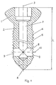
- the bone screw with the central longitudinal axis 3 and the total length L has a head 1, to which a shaft 2 with a screw tip 4 connects.
- the outer surface 5 of the shaft 2 has an external thread 6.
- Coaxial to the longitudinal axis 3 is a bore 7 which is open towards the head 1 and which is connected to the lateral surface 5 of the shaft 2 via a channel 8 running transversely to the longitudinal axis 3 and opens out in the form of two perforations 9 through the lateral surface 5 ,
- the bore 7 is closed to the screw tip 4.
- the central axes 10 of the two perforations 9, measured on the longitudinal axis 3, are at a distance of approximately 0.28 L from the screw tip 4.
- the opening of the bore 7 opening in the head 1 of the bone screw is designed as a hexagon cavity which can accommodate a corresponding screwdriver.
Landscapes
- Health & Medical Sciences (AREA)
- Orthopedic Medicine & Surgery (AREA)
- Life Sciences & Earth Sciences (AREA)
- Surgery (AREA)
- Neurology (AREA)
- Heart & Thoracic Surgery (AREA)
- General Health & Medical Sciences (AREA)
- Biomedical Technology (AREA)
- Nuclear Medicine, Radiotherapy & Molecular Imaging (AREA)
- Medical Informatics (AREA)
- Molecular Biology (AREA)
- Animal Behavior & Ethology (AREA)
- Engineering & Computer Science (AREA)
- Public Health (AREA)
- Veterinary Medicine (AREA)
- Surgical Instruments (AREA)
- Prostheses (AREA)
- Medicinal Preparation (AREA)
- Materials For Medical Uses (AREA)
Description
Aus der DE-A-3 508 759 ist eine Hüftschraube bekannt, welche eine durchgehende zentrale Bohrung aufweist, welche in die offene Schraubenspitze mündet und seitliche Perforationen zwischen den Gewindegangwänden aufweist. Mittels dieser Hüftschraube soll einerseits eine Verankerung des überdimensionierten und spitzen Gewindes im Knochen erreicht werden und gleichzeitig durch Einspritzen von Knochenzement in die zentrale Bohrung und Austritt in die seitlichen Perforationen eine verfestigung des geschwächten Knochenmaterials erreicht werden. Der Nachteil dieser Hüftschraube besteht darin, dass sie nach erfolgter Aushärtung des Zementes nicht mehr weiter axial nach vorne eingedreht werden kann, da der durch die offene Spitze ausgetretene, und ausgehärtete Zement dies nicht mehr zulässt.
Aus der JP-07051292-A sowie der JP-07222752-A sind ebenfalls zentral durchbohrte Knochenschrauben bekannt, welche allerdings über die gesamte Länge, d.h. von der Schraubenspitze bis zum Schraubenkopf Perforationen aufweisen. Der Nachteil dieser beiden Schrauben besteht darin, dass auch im proximalen Teil der Schrauben Knochenzement austritt, was klinisch unerwünscht ist. Hier will die Erfindung Abhilfe schaffen. Der Erfindung liegt die Aufgabe zugrunde, eine teilweise durchbohrte Knochenschraube zu schaffen, durch welche Knochenzement derart in den umliegenden Knochen einbringbar ist, dass sich ein künstliches, koaxiales Zementbett für das Gewinde der Knochenschraube ausbildet, welches jedoch nur lateral an die Schraube angrenzt, so dass diese auch nach erfolgter Erhärtung des Zementes weiter axial nach vorne eingedreht (nachgezogen) werden kann.
Die Mittelachsen der Perforationen sollten, auf der Längsachse gemessen, einen Abstand von höchstens 0,5 L zur Schraubenspitze hin aufweisen.
Der Durchmesser des Aussengewindes sollte höchstens 7,5 mm betragen und vorzugsweise im Bereich von 3,0 bis 7,5 mm liegen.
Die Mittelachsen 10 der zwei Perforationen 9 weisen, auf der Längsachse 3 gemessen, einen Abstand von ca. 0,28 L zur Schraubenspitze 4 hin auf.
Die im Kopf 1 der Knochenschraube mündende Öffnung der Bohrung 7 ist als Sechskant-Kavität ausgebildet, welche einen entsprechenden Schraubenzieher aufnehmen kann..
Claims (11)
- Knochenschraube mit einem Kopf (1), einem Schaft (2), einer zentralen Längsachse (3), einer Schraubenspitze (4), einer Mantelfläche (5), einem Aussengewinde (6) und einer Gesamtlänge L, wobei eine koaxial zur Längsachse (3) verlaufende, gegen den Kopf (1) hin offene Bohrung (7) vorgesehen ist, welche über mindestens einen, quer zur Längsachse (3) verlaufenden Kanal (8) mit der Mantelfläche (5) verbunden ist und in Form von mindestens einer Perforation (9) durch die Mantelfläche (5) nach aussen mündet, wobei die Bohrung (7) zur Schraubenspitze (4) hin verschlossen ist,
dadurch gekennzeichnet, dass
die Mittelachsen (10) der Perforationen (9), auf der Längsachse (3) gemessen, einen Abstand von höchstens 0,5 L zur Schraubenspitze (4) aufweisen; und das Verhältnis D/F zwischen Aussengewindedurchmesser D in mm und der Gesamtaustrittsfläche F der Perforationen (9) in mm2 im Bereich von 0,1 bis 0,9 mm-1 liegt. - Knochenschraube nach Anspruch 1, dadurch gekennzeichnet, dass der Flankenwinkel des Aussengewinde (6) grösser als 25° ist, und vorzugsweise im Bereich von 29° bis 61° liegt.
- Knochenschraube nach einem der Ansprüche 1 bis 2, dadurch gekennzeichnet, dass der Durchmesser des Aussengewinde (6) höchstens 7,5 mm beträgt.
- Knochenschraube nach einem der Ansprüche 1 bis 3, dadurch gekennzeichnet, dass der Durchmesser der Perforationen (9) im Bereich von 0,9 bis 3,3 mm liegt.
- Knochenschraube nach einem der Ansprüche 1 bis 4, dadurch gekennzeichnet, dass die Anzahl der Perforationen (9) im Bereich von 1 bis 8 liegt.
- Knochenschraube nach Anspruch 5, dadurch gekennzeichnet, dass die Perforationen (9), relativ zur Längsachse (3), auf ein bis drei orthogonal dazu stehenden Ebenen angeordnet sind.
- Knochenschraube nach einem der Ansprüche 1 bis 6, dadurch gekennzeichnet, dass die im Kopf (1) mündende Öffnung der Bohrung (7) als Steckverbindung für einen Adapter zur Kopplung mit einer Knochenzementspritze ausgebildet ist.
- Knochenschraube nach einem der Ansprüche 1 bis 7, dadurch gekennzeichnet, dass das Verhältnis D/d zwischen Aussengewindedurchmesser D und dem Durchmesser d der Bohrung (7) im Bereich von 2,0 bis 2;9 liegt.
- Knochenschraube nach einem der Ansprüche 1 bis 8, dadurch gekennzeichnet, dass die Perforationen (9) in den Bereich der Gewindegangwände reichen.
- Knochenschraube nach einem der Ansprüche 1 bis 9, mit einem Adapter zur Kopplung mit einer Knochenzementspritze.
- Fixationssystem mit mindestens zwei Knochenschrauben nach einem der Ansprüche 1 bis 10, dadurch gekennzeichnet, dass es eine Knochenplatte mit mehreren Plattenbohrungen zur Aufnahme der Knochenschrauben umfasst.
Applications Claiming Priority (1)
| Application Number | Priority Date | Filing Date | Title |
|---|---|---|---|
| PCT/CH1999/000419 WO2001017447A1 (de) | 1999-09-08 | 1999-09-08 | Knochenschraube |
Publications (3)
| Publication Number | Publication Date |
|---|---|
| EP1210019A1 EP1210019A1 (de) | 2002-06-05 |
| EP1210019B1 true EP1210019B1 (de) | 2004-10-20 |
| EP1210019B2 EP1210019B2 (de) | 2009-07-15 |
Family
ID=4551715
Family Applications (1)
| Application Number | Title | Priority Date | Filing Date |
|---|---|---|---|
| EP99939893A Expired - Lifetime EP1210019B2 (de) | 1999-09-08 | 1999-09-08 | verwendung einer knochenschraube |
Country Status (12)
| Country | Link |
|---|---|
| EP (1) | EP1210019B2 (de) |
| JP (1) | JP4145044B2 (de) |
| KR (1) | KR100656573B1 (de) |
| CN (1) | CN1261082C (de) |
| AT (1) | ATE279887T1 (de) |
| AU (1) | AU757039B2 (de) |
| CA (1) | CA2405230C (de) |
| DE (1) | DE59910917D1 (de) |
| ES (1) | ES2228085T5 (de) |
| NZ (1) | NZ517314A (de) |
| TW (1) | TW466310B (de) |
| WO (1) | WO2001017447A1 (de) |
Cited By (2)
| Publication number | Priority date | Publication date | Assignee | Title |
|---|---|---|---|---|
| EP2856958A1 (de) | 2013-10-07 | 2015-04-08 | Arthrex Inc | Kanülierte Knochenschraube |
| EP4124356A1 (de) | 2021-07-28 | 2023-02-01 | Heraeus Medical GmbH | Vorrichtung und verfahren zur applikation eines pharmazeutischen fluids |
Families Citing this family (13)
| Publication number | Priority date | Publication date | Assignee | Title |
|---|---|---|---|---|
| DE102004011612A1 (de) * | 2004-03-10 | 2005-09-29 | Ulrich Gmbh & Co. Kg | Pedikelschraube |
| US20050021084A1 (en) * | 2003-05-19 | 2005-01-27 | Lu William Weijia | Bone treatment device and method |
| US7250055B1 (en) * | 2003-08-26 | 2007-07-31 | Biomet Manufacturing Corp. | Method and apparatus for cement delivering buttress pin |
| GB2417536B (en) * | 2004-08-28 | 2006-09-06 | Adam James | A bioabsorable screw |
| US20100211113A1 (en) | 2009-02-17 | 2010-08-19 | Jon Olson | Bone Screw With Channels |
| CN101548907B (zh) * | 2009-05-14 | 2011-06-01 | 梁德富 | 逆顺自锁式防松骨钉 |
| TR200904029A2 (tr) | 2009-05-25 | 2009-10-21 | Murat Aydin Hali̇l | Bir biyomalzeme. |
| US8574273B2 (en) | 2009-09-09 | 2013-11-05 | Innovision, Inc. | Bone screws and methods of use thereof |
| KR101885506B1 (ko) * | 2010-05-13 | 2018-08-07 | 신세스 게엠바하 | 뼈 나사 어셈블리 및 이의 이식을 위한 기구 |
| DE102011001264A1 (de) | 2011-03-14 | 2012-09-20 | Aesculap Ag | Chirurgischer K-Draht und chirurgisches Schraubensystem |
| CN103654934B (zh) * | 2012-08-30 | 2016-03-30 | 上海微创骨科医疗科技有限公司 | 用于接骨板的组合式锁定螺钉及包括其的接骨板系统 |
| CN103006307B (zh) * | 2012-12-14 | 2015-06-03 | 深圳先进技术研究院 | 骨质疏松骨固定的骨螺钉 |
| EP2967694B1 (de) | 2013-03-15 | 2022-04-20 | INNOVISION, Inc. | Knochenschrauben |
Family Cites Families (6)
| Publication number | Priority date | Publication date | Assignee | Title |
|---|---|---|---|---|
| CA1227902A (en) * | 1984-04-02 | 1987-10-13 | Raymond G. Tronzo | Fenestrated hip screw and method of augmented internal fixation |
| WO1988006023A1 (en) † | 1987-02-20 | 1988-08-25 | Klaus Draenert | Suction drainage-bone screw |
| US5098435A (en) † | 1990-11-21 | 1992-03-24 | Alphatec Manufacturing Inc. | Cannula |
| JPH0751292A (ja) * | 1993-08-16 | 1995-02-28 | Yoshihiro Kishigami | 骨内留置用骨ネジ |
| JPH07222752A (ja) * | 1994-02-09 | 1995-08-22 | Terumo Corp | 骨固定用具 |
| US6214012B1 (en) † | 1998-11-13 | 2001-04-10 | Harrington Arthritis Research Center | Method and apparatus for delivering material to a desired location |
-
1999
- 1999-09-08 KR KR1020027003139A patent/KR100656573B1/ko not_active Expired - Fee Related
- 1999-09-08 CN CNB998168955A patent/CN1261082C/zh not_active Expired - Fee Related
- 1999-09-08 AU AU54052/99A patent/AU757039B2/en not_active Ceased
- 1999-09-08 CA CA002405230A patent/CA2405230C/en not_active Expired - Fee Related
- 1999-09-08 WO PCT/CH1999/000419 patent/WO2001017447A1/de not_active Ceased
- 1999-09-08 DE DE59910917T patent/DE59910917D1/de not_active Expired - Lifetime
- 1999-09-08 EP EP99939893A patent/EP1210019B2/de not_active Expired - Lifetime
- 1999-09-08 JP JP2001521241A patent/JP4145044B2/ja not_active Expired - Fee Related
- 1999-09-08 ES ES99939893T patent/ES2228085T5/es not_active Expired - Lifetime
- 1999-09-08 AT AT99939893T patent/ATE279887T1/de not_active IP Right Cessation
- 1999-09-08 NZ NZ517314A patent/NZ517314A/xx not_active IP Right Cessation
-
2000
- 2000-09-16 TW TW089119034A patent/TW466310B/zh not_active IP Right Cessation
Cited By (2)
| Publication number | Priority date | Publication date | Assignee | Title |
|---|---|---|---|---|
| EP2856958A1 (de) | 2013-10-07 | 2015-04-08 | Arthrex Inc | Kanülierte Knochenschraube |
| EP4124356A1 (de) | 2021-07-28 | 2023-02-01 | Heraeus Medical GmbH | Vorrichtung und verfahren zur applikation eines pharmazeutischen fluids |
Also Published As
| Publication number | Publication date |
|---|---|
| AU757039B2 (en) | 2003-01-30 |
| EP1210019B2 (de) | 2009-07-15 |
| WO2001017447A1 (de) | 2001-03-15 |
| ES2228085T5 (es) | 2009-12-09 |
| CN1261082C (zh) | 2006-06-28 |
| CA2405230C (en) | 2007-11-20 |
| AU5405299A (en) | 2001-04-10 |
| JP2003508147A (ja) | 2003-03-04 |
| DE59910917D1 (de) | 2004-11-25 |
| EP1210019A1 (de) | 2002-06-05 |
| TW466310B (en) | 2001-12-01 |
| NZ517314A (en) | 2003-06-30 |
| KR20020035642A (ko) | 2002-05-13 |
| CN1367665A (zh) | 2002-09-04 |
| JP4145044B2 (ja) | 2008-09-03 |
| ES2228085T3 (es) | 2005-04-01 |
| ATE279887T1 (de) | 2004-11-15 |
| KR100656573B1 (ko) | 2007-01-30 |
| CA2405230A1 (en) | 2002-10-07 |
Similar Documents
| Publication | Publication Date | Title |
|---|---|---|
| EP0053999B1 (de) | Osteosynthetische Vorrichtung und dazu passende Bohrlehre | |
| EP1800615B1 (de) | Knochenplatte | |
| EP1210019B1 (de) | Knochenschraube | |
| EP1246578B1 (de) | Knochenschraube | |
| EP1718229B1 (de) | Knochenschraube | |
| EP1608278B1 (de) | Aufnahme für ein verblockungselement und verblockungselement | |
| EP1175181B1 (de) | Verblockbare knochenplatte | |
| EP1601297B1 (de) | Verriegelungsschraube für marknagel | |
| EP0917449B1 (de) | Vorrichtung zum fixieren abgebrochener hüftgelenkköpfe | |
| EP1294298B1 (de) | Knochenplatte für die osteosynthese | |
| DE69930867T2 (de) | Fixierungsgerät | |
| DE19629011C2 (de) | Hilfsmittel für die Osteosynthese | |
| DE20122742U1 (de) | Knochenplatte zur Fixation von proximalen Humerusfrakturen | |
| EP1622527B1 (de) | Implantat mit einem fixierkörper für eine knochenschraube | |
| DE202006019220U1 (de) | Orthopädisches Schraubenverschlusssystem | |
| EP1486175A2 (de) | Osteosyntheseplatte oder vergleichbares Implantat nebst Kugelhülse | |
| DE4341980A1 (de) | Osteosynthetische Knochenplatte | |
| DE8900121U1 (de) | Vorrichtung zur Kompressionsverschraubung | |
| EP1605845A1 (de) | Intramedullärer marknagel | |
| EP1758513B1 (de) | Chirurgischer nagel | |
| DE10039767B4 (de) | Befestigungsanordnung | |
| DE102012211638A1 (de) | Verankerungssystem | |
| EP1675517B1 (de) | Vorrichtung zur knochenfixation | |
| WO2004000144A1 (de) | Knochenschraube mit tangentialer schneidkante | |
| WO2003053265A1 (de) | Modularer knochennagel |
Legal Events
| Date | Code | Title | Description |
|---|---|---|---|
| PUAI | Public reference made under article 153(3) epc to a published international application that has entered the european phase |
Free format text: ORIGINAL CODE: 0009012 |
|
| 17P | Request for examination filed |
Effective date: 20020204 |
|
| AK | Designated contracting states |
Kind code of ref document: A1 Designated state(s): AT BE CH CY DE DK ES FI FR GB GR IE IT LI LU MC NL PT SE |
|
| 17Q | First examination report despatched |
Effective date: 20030318 |
|
| GRAP | Despatch of communication of intention to grant a patent |
Free format text: ORIGINAL CODE: EPIDOSNIGR1 |
|
| GRAS | Grant fee paid |
Free format text: ORIGINAL CODE: EPIDOSNIGR3 |
|
| GRAA | (expected) grant |
Free format text: ORIGINAL CODE: 0009210 |
|
| AK | Designated contracting states |
Kind code of ref document: B1 Designated state(s): AT BE CH CY DE DK ES FI FR GB GR IE IT LI LU MC NL PT SE |
|
| PG25 | Lapsed in a contracting state [announced via postgrant information from national office to epo] |
Ref country code: IE Free format text: LAPSE BECAUSE OF FAILURE TO SUBMIT A TRANSLATION OF THE DESCRIPTION OR TO PAY THE FEE WITHIN THE PRESCRIBED TIME-LIMIT Effective date: 20041020 Ref country code: FR Free format text: LAPSE BECAUSE OF FAILURE TO SUBMIT A TRANSLATION OF THE DESCRIPTION OR TO PAY THE FEE WITHIN THE PRESCRIBED TIME-LIMIT Effective date: 20041020 Ref country code: FI Free format text: LAPSE BECAUSE OF FAILURE TO SUBMIT A TRANSLATION OF THE DESCRIPTION OR TO PAY THE FEE WITHIN THE PRESCRIBED TIME-LIMIT Effective date: 20041020 |
|
| REG | Reference to a national code |
Ref country code: GB Ref legal event code: FG4D Free format text: NOT ENGLISH |
|
| REG | Reference to a national code |
Ref country code: CH Ref legal event code: EP |
|
| REG | Reference to a national code |
Ref country code: CH Ref legal event code: NV Representative=s name: DR. LUSUARDI AG |
|
| REG | Reference to a national code |
Ref country code: IE Ref legal event code: FG4D Free format text: GERMAN |
|
| REF | Corresponds to: |
Ref document number: 59910917 Country of ref document: DE Date of ref document: 20041125 Kind code of ref document: P |
|
| PG25 | Lapsed in a contracting state [announced via postgrant information from national office to epo] |
Ref country code: SE Free format text: LAPSE BECAUSE OF FAILURE TO SUBMIT A TRANSLATION OF THE DESCRIPTION OR TO PAY THE FEE WITHIN THE PRESCRIBED TIME-LIMIT Effective date: 20050120 Ref country code: GR Free format text: LAPSE BECAUSE OF FAILURE TO SUBMIT A TRANSLATION OF THE DESCRIPTION OR TO PAY THE FEE WITHIN THE PRESCRIBED TIME-LIMIT Effective date: 20050120 Ref country code: DK Free format text: LAPSE BECAUSE OF FAILURE TO SUBMIT A TRANSLATION OF THE DESCRIPTION OR TO PAY THE FEE WITHIN THE PRESCRIBED TIME-LIMIT Effective date: 20050120 |
|
| GBT | Gb: translation of ep patent filed (gb section 77(6)(a)/1977) |
Effective date: 20050118 |
|
| REG | Reference to a national code |
Ref country code: ES Ref legal event code: FG2A Ref document number: 2228085 Country of ref document: ES Kind code of ref document: T3 |
|
| REG | Reference to a national code |
Ref country code: IE Ref legal event code: FD4D |
|
| PLBI | Opposition filed |
Free format text: ORIGINAL CODE: 0009260 |
|
| PLAX | Notice of opposition and request to file observation + time limit sent |
Free format text: ORIGINAL CODE: EPIDOSNOBS2 |
|
| PG25 | Lapsed in a contracting state [announced via postgrant information from national office to epo] |
Ref country code: CY Free format text: LAPSE BECAUSE OF FAILURE TO SUBMIT A TRANSLATION OF THE DESCRIPTION OR TO PAY THE FEE WITHIN THE PRESCRIBED TIME-LIMIT Effective date: 20050908 |
|
| 26 | Opposition filed |
Opponent name: AESCULAP AG & CO. KG Effective date: 20050720 |
|
| PG25 | Lapsed in a contracting state [announced via postgrant information from national office to epo] |
Ref country code: MC Free format text: LAPSE BECAUSE OF NON-PAYMENT OF DUE FEES Effective date: 20050930 Ref country code: LU Free format text: LAPSE BECAUSE OF NON-PAYMENT OF DUE FEES Effective date: 20050930 Ref country code: BE Free format text: LAPSE BECAUSE OF NON-PAYMENT OF DUE FEES Effective date: 20050930 |
|
| NLR1 | Nl: opposition has been filed with the epo |
Opponent name: AESCULAP AG & CO. KG |
|
| PLBB | Reply of patent proprietor to notice(s) of opposition received |
Free format text: ORIGINAL CODE: EPIDOSNOBS3 |
|
| EN | Fr: translation not filed | ||
| PGFP | Annual fee paid to national office [announced via postgrant information from national office to epo] |
Ref country code: NL Payment date: 20060726 Year of fee payment: 8 |
|
| REG | Reference to a national code |
Ref country code: CH Ref legal event code: PUE Owner name: SYNTHES GMBH Free format text: SYNTHES AG CHUR#GRABENSTRASSE 15#7002 CHUR (CH) -TRANSFER TO- SYNTHES GMBH#EIMATTSTRASSE 3#4436 OBERDORF (CH) |
|
| REG | Reference to a national code |
Ref country code: GB Ref legal event code: 732E |
|
| RDAF | Communication despatched that patent is revoked |
Free format text: ORIGINAL CODE: EPIDOSNREV1 |
|
| NLS | Nl: assignments of ep-patents |
Owner name: SYNTHES GMBH Effective date: 20061030 |
|
| APBP | Date of receipt of notice of appeal recorded |
Free format text: ORIGINAL CODE: EPIDOSNNOA2O |
|
| APAH | Appeal reference modified |
Free format text: ORIGINAL CODE: EPIDOSCREFNO |
|
| APBQ | Date of receipt of statement of grounds of appeal recorded |
Free format text: ORIGINAL CODE: EPIDOSNNOA3O |
|
| BERE | Be: lapsed |
Owner name: *SYNTHES A.G. CHUR Effective date: 20050930 |
|
| PG25 | Lapsed in a contracting state [announced via postgrant information from national office to epo] |
Ref country code: PT Free format text: LAPSE BECAUSE OF NON-PAYMENT OF DUE FEES Effective date: 20050320 |
|
| PG25 | Lapsed in a contracting state [announced via postgrant information from national office to epo] |
Ref country code: NL Free format text: LAPSE BECAUSE OF NON-PAYMENT OF DUE FEES Effective date: 20080401 |
|
| NLV4 | Nl: lapsed or anulled due to non-payment of the annual fee |
Effective date: 20080401 |
|
| APBU | Appeal procedure closed |
Free format text: ORIGINAL CODE: EPIDOSNNOA9O |
|
| RTI2 | Title (correction) |
Free format text: USE OF A BONE SCREW |
|
| PUAH | Patent maintained in amended form |
Free format text: ORIGINAL CODE: 0009272 |
|
| STAA | Information on the status of an ep patent application or granted ep patent |
Free format text: STATUS: PATENT MAINTAINED AS AMENDED |
|
| 27A | Patent maintained in amended form |
Effective date: 20090715 |
|
| AK | Designated contracting states |
Kind code of ref document: B2 Designated state(s): AT BE CH CY DE DK ES FI FR GB GR IE IT LI LU MC NL PT SE |
|
| REG | Reference to a national code |
Ref country code: CH Ref legal event code: AEN Free format text: AUFRECHTERHALTUNG DES PATENTES IN GEAENDERTER FORM |
|
| PGFP | Annual fee paid to national office [announced via postgrant information from national office to epo] |
Ref country code: AT Payment date: 20090911 Year of fee payment: 11 |
|
| REG | Reference to a national code |
Ref country code: ES Ref legal event code: DC2A Date of ref document: 20091014 Kind code of ref document: T5 |
|
| PGFP | Annual fee paid to national office [announced via postgrant information from national office to epo] |
Ref country code: ES Payment date: 20091006 Year of fee payment: 11 |
|
| PG25 | Lapsed in a contracting state [announced via postgrant information from national office to epo] |
Ref country code: AT Free format text: LAPSE BECAUSE OF NON-PAYMENT OF DUE FEES Effective date: 20100908 |
|
| REG | Reference to a national code |
Ref country code: ES Ref legal event code: FD2A Effective date: 20111019 |
|
| PG25 | Lapsed in a contracting state [announced via postgrant information from national office to epo] |
Ref country code: ES Free format text: LAPSE BECAUSE OF NON-PAYMENT OF DUE FEES Effective date: 20100909 |
|
| PGFP | Annual fee paid to national office [announced via postgrant information from national office to epo] |
Ref country code: CH Payment date: 20130912 Year of fee payment: 15 Ref country code: DE Payment date: 20130904 Year of fee payment: 15 |
|
| PGFP | Annual fee paid to national office [announced via postgrant information from national office to epo] |
Ref country code: GB Payment date: 20130904 Year of fee payment: 15 |
|
| PGFP | Annual fee paid to national office [announced via postgrant information from national office to epo] |
Ref country code: IT Payment date: 20130909 Year of fee payment: 15 |
|
| REG | Reference to a national code |
Ref country code: DE Ref legal event code: R119 Ref document number: 59910917 Country of ref document: DE |
|
| REG | Reference to a national code |
Ref country code: CH Ref legal event code: PL |
|
| GBPC | Gb: european patent ceased through non-payment of renewal fee |
Effective date: 20140908 |
|
| REG | Reference to a national code |
Ref country code: DE Ref legal event code: R119 Ref document number: 59910917 Country of ref document: DE Effective date: 20150401 |
|
| PG25 | Lapsed in a contracting state [announced via postgrant information from national office to epo] |
Ref country code: LI Free format text: LAPSE BECAUSE OF NON-PAYMENT OF DUE FEES Effective date: 20140930 Ref country code: DE Free format text: LAPSE BECAUSE OF NON-PAYMENT OF DUE FEES Effective date: 20150401 Ref country code: CH Free format text: LAPSE BECAUSE OF NON-PAYMENT OF DUE FEES Effective date: 20140930 Ref country code: GB Free format text: LAPSE BECAUSE OF NON-PAYMENT OF DUE FEES Effective date: 20140908 |
|
| PG25 | Lapsed in a contracting state [announced via postgrant information from national office to epo] |
Ref country code: IT Free format text: LAPSE BECAUSE OF NON-PAYMENT OF DUE FEES Effective date: 20140908 |