EP4123315B1 - Sicherheits-kontaktiervorrichtung zum erkennen von kabeln von solarzellen und zum messen von gleich- und wechselspannungen und strömen an weiteren spannungsführenden kabeln - Google Patents
Sicherheits-kontaktiervorrichtung zum erkennen von kabeln von solarzellen und zum messen von gleich- und wechselspannungen und strömen an weiteren spannungsführenden kabeln Download PDFInfo
- Publication number
- EP4123315B1 EP4123315B1 EP22020350.9A EP22020350A EP4123315B1 EP 4123315 B1 EP4123315 B1 EP 4123315B1 EP 22020350 A EP22020350 A EP 22020350A EP 4123315 B1 EP4123315 B1 EP 4123315B1
- Authority
- EP
- European Patent Office
- Prior art keywords
- cable
- measuring electrode
- contact device
- safety contact
- cables
- Prior art date
- Legal status (The legal status is an assumption and is not a legal conclusion. Google has not performed a legal analysis and makes no representation as to the accuracy of the status listed.)
- Active
Links
Images


Classifications
-
- G—PHYSICS
- G01—MEASURING; TESTING
- G01R—MEASURING ELECTRIC VARIABLES; MEASURING MAGNETIC VARIABLES
- G01R1/00—Details of instruments or arrangements of the types included in groups G01R5/00 - G01R13/00 and G01R31/00
- G01R1/02—General constructional details
- G01R1/04—Housings; Supporting members; Arrangements of terminals
- G01R1/0408—Test fixtures or contact fields; Connectors or connecting adaptors; Test clips; Test sockets
- G01R1/0416—Connectors, terminals
-
- H—ELECTRICITY
- H02—GENERATION; CONVERSION OR DISTRIBUTION OF ELECTRIC POWER
- H02S—GENERATION OF ELECTRIC POWER BY CONVERSION OF INFRARED RADIATION, VISIBLE LIGHT OR ULTRAVIOLET LIGHT, e.g. USING PHOTOVOLTAIC [PV] MODULES
- H02S50/00—Monitoring or testing of PV systems, e.g. load balancing or fault identification
- H02S50/10—Testing of PV devices, e.g. of PV modules or single PV cells
-
- G—PHYSICS
- G01—MEASURING; TESTING
- G01R—MEASURING ELECTRIC VARIABLES; MEASURING MAGNETIC VARIABLES
- G01R1/00—Details of instruments or arrangements of the types included in groups G01R5/00 - G01R13/00 and G01R31/00
- G01R1/02—General constructional details
- G01R1/06—Measuring leads; Measuring probes
- G01R1/067—Measuring probes
- G01R1/06788—Hand-held or hand-manipulated probes, e.g. for oscilloscopes or for portable test instruments
-
- G—PHYSICS
- G01—MEASURING; TESTING
- G01R—MEASURING ELECTRIC VARIABLES; MEASURING MAGNETIC VARIABLES
- G01R31/00—Arrangements for testing electric properties; Arrangements for locating electric faults; Arrangements for electrical testing characterised by what is being tested not provided for elsewhere
- G01R31/50—Testing of electric apparatus, lines, cables or components for short-circuits, continuity, leakage current or incorrect line connections
- G01R31/55—Testing for incorrect line connections
-
- Y—GENERAL TAGGING OF NEW TECHNOLOGICAL DEVELOPMENTS; GENERAL TAGGING OF CROSS-SECTIONAL TECHNOLOGIES SPANNING OVER SEVERAL SECTIONS OF THE IPC; TECHNICAL SUBJECTS COVERED BY FORMER USPC CROSS-REFERENCE ART COLLECTIONS [XRACs] AND DIGESTS
- Y02—TECHNOLOGIES OR APPLICATIONS FOR MITIGATION OR ADAPTATION AGAINST CLIMATE CHANGE
- Y02E—REDUCTION OF GREENHOUSE GAS [GHG] EMISSIONS, RELATED TO ENERGY GENERATION, TRANSMISSION OR DISTRIBUTION
- Y02E10/00—Energy generation through renewable energy sources
- Y02E10/50—Photovoltaic [PV] energy
Definitions
- the invention relates to a safety contact device for detecting two cables belonging to each other in a solar cell series connection.
- Solar cells which are often also called solar panels, are arranged on the walls and roofs of houses. Solar cells convert solar energy into electrical energy. They are usually connected in series to add the direct voltages they generate.
- a start cable runs from the roof or wall of a house downwards from the first solar cell, and an end cable runs downwards from the last solar cell of the solar cells connected in series.
- the two cables are usually led into a basement or utility room of a building to be wired there.
- the technician in a basement or utility room is faced with the task of finding out from a tangled bundle of many cables the two cables that belong together and form a pair, namely the respective starting cable of a first solar cell connected in series and the corresponding end cable of the last solar cell in the series.
- each cable must be picked up by the installer and the metal cable core of each cable must be physically contacted using a measuring electrode, for example a cable leading to a multimeter.
- the technician In order to detect the direct current, the technician must first pick up a first cable and bring it into contact with a first measuring electrode. The technician must hold this first measuring electrode and the first cable in contact with one hand, while the technician then uses the other hand to identify the cable belonging to the first cable from the bundle of cables by placing a second measuring electrode on the metal core of a second cable. The technician must therefore test all of the remaining cables until he has found the right one. There is a risk that the technician will slip off a metal core and touch the metal core with his finger. If the human body comes into direct contact with the metal cable cores of such a pair, a direct current of up to 3000 volts is applied to it, which can cause considerable damage to health.
- a self-retaining clamping device is known by means of which a quick and safe electrical contact can be made with an electrical conductor, in particular for carrying out electrical measuring and testing processes.
- the clamping device consists of an electrically non-conductive cylindrical part, at the end of which a rectangular groove is machined.
- An eccentric, rotatable, non-toothed tension roller made of non-conductive material with a high coefficient of friction is arranged in the rectangular groove transversely to the axial direction.
- a cylindrical bore is arranged in the interior of the cylindrical part in the axial direction, which opens or ends in the rectangular groove.
- the conductor end of a conductor to be tested is guided into the groove between the groove base and the tension roller until its cross-sectional area hits a contact surface of a contact piston and the contact piston is moved in the axial direction against the force of the helical spring, so that an electrical contact is made over the contact piston surface and the cross-sectional area of the conductor.
- the tension roller is automatically held in this position by the force of the coil spring on the conductor.
- the clamping device of the DD 120 978 A1 can be used in particular for testing a large number of insulated single conductors to carry out a voltage test of each individual conductor against all other individual conductors.
- the invention is based on the object of creating a safety contact device in which the cables in the safety contact device can be contacted more reliably than in the prior art.
- the present invention solves the above-mentioned problem by the features of claim 1.
- a safety contact device for detecting two cables of a solar cell series connection that belong together can prevent the fitter from coming into direct physical contact with the metal core of a cable. It has also been recognized that at least one first measuring electrode with a tip for contact with the core of a first cable must be guided in a direction to reliably hit the metal core of the cable without the fitter moving the measuring electrode himself. It has also been recognized that a base body with a cable holder for inserting and holding at least one of the cables can feed the cable directly when inserting the measuring electrode. It has also been recognized that the measuring electrode must be guided within the base body by guide means so that the metal core can be accurately hit and physically contacted without stripping the cable.
- the safety contact device also ensures that the technician can no longer be harmed by direct current, because the only cable that could apply a voltage to his human body, together with the cable he is holding in his hand, is already held in the safety contact device.
- the cable holder shields the cable held in it, in particular the metal core, against unwanted access.
- the guide means comprise a spring by means of which the measuring electrode is spring-mounted, whereby the spring can be moved against a restoring force.
- a cable can be pushed into the cable holder until the measuring electrode is pressed against the metal core.
- the measuring electrode offers the cable a spring-mounted resistance when it is pushed in.
- locking means are assigned to the cable holder to prevent the cable from slipping out of the cable holder.
- the locking means press against the sheath of the cable and thereby fix it in place with a force fit.
- the locking devices could be operated manually by an actuating device to release or fix the cable. This allows the installer to actively determine whether a cable should remain in the cable holder or be pulled out of it.
- the actuating device could have a lever that can be pivoted about a pivot axis.
- a lever can be easily actuated with a finger, in particular the thumb.
- the lever could be spring-loaded so that a locking means automatically presses radially inwards when the lever is not pressed or is released.
- the base body could have at least one cable with a plug, whereby the cable is electrically connected to the measuring electrode.
- the safety contact device can easily be connected to a standard measuring device for measuring electrical currents and voltages, such as a multimeter.
- the base body could have two cable receptacles, each with a measuring electrode assigned to the respective cable receptacle. This means that two cables can always be plugged into the safety contact device and the fitter can then operate the measuring device more easily.
- a cable holder could have several locking areas arranged one behind the other, each with a different inner diameter than the other locking area. This means that cables of different thicknesses can be inserted into the safety contact device described here.
- the safety contact device could be connected to a measuring device for measuring electrical currents or voltages by means of a cable, or the base body could be designed as one piece with such a measuring device.
- the one-piece design of the safety contact device or several safety contact devices with a measuring device, in particular a multimeter, makes it particularly easy to test and examine cables for solar cells.
- the safety contact device described here is preferably used for testing solar cell cables.
- the DIN standards for cables used as solar cables are as follows: DIN EN 60228 Class 5 (conductor structure), EN 60811, EN 50267-2-1, EN 50363.
- the DIN standards for measuring instruments and test adapters are as follows: IEC 61010 1 (international), DIN EN 61010 1 (German version) or VDE classification VDE 0411-1, product standards for devices for testing, measuring or monitoring protective measures: IEC 61557 Parts 1 to 16 (international), DIN EN 61557 Parts 1 to 16 (German version) or DIN VDE 0413 Parts 1 to 16.
- the currently valid product standards are EC 61010-1:2010 + Cor.:2011, DIN EN 61010-1:2011-07 and VDE 0411-1:2011-07.
- the safety contact device described here is used to detect cables from solar cells and to carry out measurements to determine direct and alternating voltages and currents on other live cables.
- Fig. 1 shows a schematic view of several rows of solar cells 1 connected in series, the respective start and end cables 2a, 3a, 4a, 2b, 3b, 4b of which are led within a tangled cable bundle with disordered cable ends into a supply room 5 of a building for further wiring by a fitter.
- a series of several solar cells 1 can build up 750 to 3000 volts between a starting cable 2a, 3a, 4a and an end cable 2b, 3b, 4b.
- a cable 2a, 3a, 4a, 2b, 3b, 4b can have a metallic core of 4 mm 2 , 6 mm 2 , 10 mm 2 or 16 mm 2 .
- Fig. 1 shows by the dashed detail A the non-stripped end of a terminal cable 2b, which forms a pair with the starting cable 2a from which a direct voltage can be tapped.
- Fig. 2 shows a schematic view of detail A from Fig. 1 , namely a cable end, the metallic core 6 of which is physically contacted by a measuring electrode 7b (more precisely: its tip), the measuring electrode 7b being connected by means of a line 8 to a multimeter 9, from which a further line 8 with another still free measuring electrode 7a branches off.
- the technician must now remove the cable bundle from Fig. 1 the starting cable 2a by bringing the still free measuring electrode 7a into contact with the other cables 2a, 3a, 4a, 3b, 4b until the multimeter 9 indicates a direct voltage.
- the fitter must ensure that he does not come into physical contact with both metal cores 6 of the starting cable 2a and the end cable 2b at the same time.
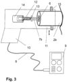
- Fig. 3 shows a schematic sectional view of a safety contact device with a spring-mounted measuring electrode 7b, which is in electrical and physical contact with a metallic core 6 of a cable, here the end cable 2b.
- This safety contact device is used to detect two cables that belong together, namely a start cable 2a and an end cable 2b, a solar cell series connection.
- the safety contacting device comprises at least one measuring electrode 7b for application to the core 6 of a cable, namely the end cable 2b, and is characterized by a base body 10 with a cable receptacle 11 for inserting and holding the end cable 2b, wherein the measuring electrode 7b is guided within the base body 10 by guide means.
- the guide means comprise a spring 12, for example a spiral spring, by means of which the measuring electrode 7b is spring-mounted, whereby the measuring electrode 7b is movable against a restoring force.
- the measuring electrode 7b is designed as an elongated contact pin, on the rim 13 of which the spring 12 is attached with a Fig. 3 right end.
- the spring 12 is supported with its left end on a guide sleeve 14, into which the contact pin can be inserted and which establishes an electrical contact between the contact pin and a line 8.
- the cable holder 11 is arranged coaxially to the axis of movement through the measuring electrode 7b.
- the axis of movement through the measuring electrode 7b coincides with the horizontal double arrow in Fig. 3
- the double arrow indicates that the measuring electrode 7b can spring in and out, depending on whether the end cable 2b is inserted into or led out of the cable holder 11, which is open on one side.
- the cable holder 11 is preferably made of a plastic or another electrically insulating material.
- the cable holder 11 is assigned locking means 15 to prevent the cable from slipping out of the cable holder 11.
- the locking means 15 can be moved radially inwards to press against the cable sheath. The cable is thus firmly fixed in the cable holder 11 when its core 6 contacts the measuring electrode 7b.
- the radial mobility of the locking means 15 is indicated by the vertical double arrow in Fig. 3 and Fig. 4 shown.
- a free measuring electrode 7a can now be used as in Fig. 2
- the installer now has both hands free, because the end cable 2b in the safety contact device according to Fig. 3 is securely fixed.
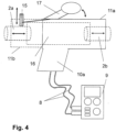
- Fig. 4 shows, based on a further embodiment of the safety contact device, that a base body 10a has two cable receptacles 11a, 11b, one of which holds the start cable 2a and the other the end cable 2b.
- a device 16 is provided inside the base body 10a, which has two spring-mounted measuring electrodes 7a, 7b in analogy to Fig. 3 This means that two cables can be examined at a time and the technician has both hands free to operate the multimeter 9.
- Fig. 4 also shows that the locking means 15 can be operated manually by an actuating device in order to release or fix a cable.
- the actuating device has a lever 17 that can be pivoted about a pivot axis. This is shown by the curved double arrow.
- both cables can also be released or fixed at the same time by one lever 17.
- two levers 17 are provided so that each cable can be released or fixed on its own.
- Fig. 3 and 4 show that the base body 10, 10a has at least one line 8 with a plug, wherein the line 8 is electrically connected to the measuring electrode 7b or 7a. If two measuring electrodes 7a, 7b are provided, two lines 8 are provided which lead to the multimeter 9.
- Fig. 4 shows against this background that the base body 10a has two cable receptacles 11a, 11b, each with a measuring electrode 7a, 7b assigned to the respective cable receptacle 11a, 11b.
- the measuring device is preferably a correspondingly modified multimeter 9.
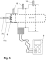
- a cable holder 11c has several locking areas arranged one behind the other, each with a different inner diameter to another, adjacent locking area.
- Fig. 5 shows such a cable holder 11c.
- the different inner diameters of the locking areas with locking means 15 are shown by dashed double arrows.
- the cable holder 11c can be equipped with a safety contact device according to Fig. 3 or 4 , but can also be combined with a modified multimeter 9 if this multimeter 9 forms the safety contact device.
- the locking area with the largest inner diameter faces away from the measuring electrode 7b, the locking area with the smallest inner diameter faces the measuring electrode 7b.
- Insertion bevels can be formed between the locking areas so that a cable can be inserted better, i.e. threaded through, so to speak.
- the installer can therefore carry a safety contact device of the type described here.
Landscapes
- Physics & Mathematics (AREA)
- General Physics & Mathematics (AREA)
- Measuring Leads Or Probes (AREA)
- Details Of Connecting Devices For Male And Female Coupling (AREA)
- Geophysics And Detection Of Objects (AREA)
Applications Claiming Priority (1)
| Application Number | Priority Date | Filing Date | Title |
|---|---|---|---|
| DE102021119095.9A DE102021119095A1 (de) | 2021-07-23 | 2021-07-23 | Sicherheits-Kontaktiervorrichtung oder Set zum Erkennen von Kabeln von Solarzellen und zum Messen von Gleich- und Wechselspannungen und Strömen an weiteren spannungsführenden Kabeln |
Publications (3)
| Publication Number | Publication Date |
|---|---|
| EP4123315A1 EP4123315A1 (de) | 2023-01-25 |
| EP4123315B1 true EP4123315B1 (de) | 2024-11-06 |
| EP4123315C0 EP4123315C0 (de) | 2024-11-06 |
Family
ID=78823396
Family Applications (1)
| Application Number | Title | Priority Date | Filing Date |
|---|---|---|---|
| EP22020350.9A Active EP4123315B1 (de) | 2021-07-23 | 2022-07-21 | Sicherheits-kontaktiervorrichtung zum erkennen von kabeln von solarzellen und zum messen von gleich- und wechselspannungen und strömen an weiteren spannungsführenden kabeln |
Country Status (4)
| Country | Link |
|---|---|
| EP (1) | EP4123315B1 (pl) |
| DE (2) | DE102021119095A1 (pl) |
| ES (1) | ES2999313T3 (pl) |
| PL (1) | PL4123315T3 (pl) |
Families Citing this family (3)
| Publication number | Priority date | Publication date | Assignee | Title |
|---|---|---|---|---|
| DE202023101512U1 (de) | 2023-03-27 | 2023-04-28 | Christian Herner | Selbsthaltende Prüfspitze für feindrähtige Einzeladerleitungen |
| DE102023107600B3 (de) | 2023-03-27 | 2024-08-22 | Christian Herner | Selbsthaltende Prüfspitze für feindrähtige Einzeladerleitungen |
| DE202024102886U1 (de) | 2024-06-03 | 2024-07-17 | Innoperform GmbH | Halterung für eine elektrische Ader |
Family Cites Families (12)
| Publication number | Priority date | Publication date | Assignee | Title |
|---|---|---|---|---|
| US2515004A (en) * | 1947-12-12 | 1950-07-11 | Kelley Koett Mfg Co | Electrical testing device |
| US3864629A (en) * | 1973-03-23 | 1975-02-04 | Patrick Danna | Electrical circuit tester |
| DD120978A1 (pl) | 1975-08-13 | 1976-07-05 | ||
| JPS60140160A (ja) * | 1983-12-27 | 1985-07-25 | Sumitomo Wiring Syst Ltd | コネクタの端子検査器 |
| US5084673A (en) * | 1989-06-15 | 1992-01-28 | Nhk Spring Co., Ltd. | Electric contact probe |
| US5834929A (en) * | 1997-08-14 | 1998-11-10 | Dietz; John Gregory | Test probe guide device |
| US7816925B1 (en) | 2007-06-20 | 2010-10-19 | Gale Robert D | Electrical continuity tester and tracer |
| EP2113945A1 (de) | 2008-04-30 | 2009-11-04 | 3S Swiss Solar Systems AG | Verfahren zur Herstellung einer Kontaktierung von Solarzellen |
| DE102010025549A1 (de) | 2010-06-29 | 2011-12-29 | Phoenix Contact Gmbh & Co. Kg | Solarsteckverbindung |
| US8922196B2 (en) | 2012-03-20 | 2014-12-30 | Paul Nicholas Chait | Multifunction test instrument probe |
| US10585132B2 (en) | 2017-06-05 | 2020-03-10 | Twitch Technologies Llc | Wire tracing system and method |
| US10938130B1 (en) | 2018-10-01 | 2021-03-02 | Paul Nicholas Chait | Plug-in point adapter for alligator clip |
-
2021
- 2021-07-23 DE DE102021119095.9A patent/DE102021119095A1/de active Pending
- 2021-11-05 DE DE202021106064.6U patent/DE202021106064U1/de not_active Expired - Lifetime
-
2022
- 2022-07-21 PL PL22020350.9T patent/PL4123315T3/pl unknown
- 2022-07-21 EP EP22020350.9A patent/EP4123315B1/de active Active
- 2022-07-21 ES ES22020350T patent/ES2999313T3/es active Active
Also Published As
| Publication number | Publication date |
|---|---|
| DE202021106064U1 (de) | 2021-11-15 |
| EP4123315A1 (de) | 2023-01-25 |
| DE102021119095A1 (de) | 2023-01-26 |
| PL4123315T3 (pl) | 2025-03-24 |
| ES2999313T3 (en) | 2025-02-25 |
| EP4123315C0 (de) | 2024-11-06 |
Similar Documents
| Publication | Publication Date | Title |
|---|---|---|
| EP4123315B1 (de) | Sicherheits-kontaktiervorrichtung zum erkennen von kabeln von solarzellen und zum messen von gleich- und wechselspannungen und strömen an weiteren spannungsführenden kabeln | |
| DE102013223694B4 (de) | Verbesserter mehrpoliger elektrischer Steckverbinder mit Federkontakten | |
| EP2224544A1 (de) | Kabelordnender Einsatz für Steckverbinder | |
| WO2013004761A1 (de) | Rundsteckverbinder mit abgeschirmtem anschlusskabel | |
| DE202011108572U1 (de) | Adapter und Set aus Reihenklemme und Adapter | |
| DE102019129291A1 (de) | Mess-System für elektrische Leiter, insbesondere HV-Leiter | |
| DE102016111565A1 (de) | Elektrisches Leiteranschlusselement | |
| EP2856561B1 (de) | Elektrische anschlussklemme | |
| DE102009027967A1 (de) | Verfahren und Vorrichtung zur Überwachung der Abisolierung von Leitungsenden | |
| DE202016101839U1 (de) | Hochvolt-Testpin mit zwei identischen Kontaktstiften und elektrische Steckverbindung mit Hochvolt-Testpin | |
| CH662013A5 (de) | Einphasige endverschluss-steckverbindung zum verbinden eines kabelleiters mit einem schaltgeraet, insbesondere mit einer sf(6)-schaltanlage. | |
| DE19813753A1 (de) | Kontaktklemme | |
| EP4487130A1 (de) | Klemme | |
| EP3590153A1 (de) | Kabelbrückenmodul zur flexiblen verknüpfung von verbindungsklemmen | |
| DE102013211058B3 (de) | Stromkontaktzange für eine Vier-Leiter-Messung im Bereich Hochvolt und Hochstrom | |
| DE102021122162A1 (de) | Kompakter messfühler für messungen an einem batteriemodul | |
| WO2017178327A1 (de) | Kabel zum prüfen eines prüflings, prüfvorrichtung und verfahren zum prüfen eines prüflings | |
| EP2885645A1 (de) | Vorrichtung und verfahren zur reversiblen, mechanischen fixierung und elektrischen kontaktierung elektrischer leiter | |
| DE102021209852A1 (de) | Kontaktvorrichtung einer Testvorrichtung für eine elektrische Isolationsprüfung | |
| DE102019117554B4 (de) | Fanggabel zum Kontaktieren eines elektrischen Leiters | |
| DE10026088C1 (de) | Muffenisolierkörper mit Schraubverbinder zur Herstellung einer Kabelverbindung für Mittelspannungs-Kunststoffkabel | |
| DE102006021859B4 (de) | Steckverbinder mit Zuleitung | |
| DE102013218716A1 (de) | Prüfeinrichtung für elektrische Komponenten | |
| EP3443618A1 (de) | Steckverbinder mit leitgummi | |
| DE4419200C2 (de) | Spannungsprüfer |
Legal Events
| Date | Code | Title | Description |
|---|---|---|---|
| PUAI | Public reference made under article 153(3) epc to a published international application that has entered the european phase |
Free format text: ORIGINAL CODE: 0009012 |
|
| STAA | Information on the status of an ep patent application or granted ep patent |
Free format text: STATUS: THE APPLICATION HAS BEEN PUBLISHED |
|
| AK | Designated contracting states |
Kind code of ref document: A1 Designated state(s): AL AT BE BG CH CY CZ DE DK EE ES FI FR GB GR HR HU IE IS IT LI LT LU LV MC MK MT NL NO PL PT RO RS SE SI SK SM TR |
|
| STAA | Information on the status of an ep patent application or granted ep patent |
Free format text: STATUS: REQUEST FOR EXAMINATION WAS MADE |
|
| 17P | Request for examination filed |
Effective date: 20230228 |
|
| RBV | Designated contracting states (corrected) |
Designated state(s): AL AT BE BG CH CY CZ DE DK EE ES FI FR GB GR HR HU IE IS IT LI LT LU LV MC MK MT NL NO PL PT RO RS SE SI SK SM TR |
|
| RIC1 | Information provided on ipc code assigned before grant |
Ipc: H02S 50/10 20140101ALN20240425BHEP Ipc: G01R 31/55 20200101ALN20240425BHEP Ipc: G01R 1/067 20060101ALN20240425BHEP Ipc: G01R 1/04 20060101AFI20240425BHEP |
|
| GRAP | Despatch of communication of intention to grant a patent |
Free format text: ORIGINAL CODE: EPIDOSNIGR1 |
|
| STAA | Information on the status of an ep patent application or granted ep patent |
Free format text: STATUS: GRANT OF PATENT IS INTENDED |
|
| RIC1 | Information provided on ipc code assigned before grant |
Ipc: H02S 50/10 20140101ALN20240517BHEP Ipc: G01R 31/55 20200101ALN20240517BHEP Ipc: G01R 1/067 20060101ALN20240517BHEP Ipc: G01R 1/04 20060101AFI20240517BHEP |
|
| RIC1 | Information provided on ipc code assigned before grant |
Ipc: H02S 50/10 20140101ALN20240524BHEP Ipc: G01R 31/55 20200101ALN20240524BHEP Ipc: G01R 1/067 20060101ALN20240524BHEP Ipc: G01R 1/04 20060101AFI20240524BHEP |
|
| INTG | Intention to grant announced |
Effective date: 20240613 |
|
| GRAS | Grant fee paid |
Free format text: ORIGINAL CODE: EPIDOSNIGR3 |
|
| GRAA | (expected) grant |
Free format text: ORIGINAL CODE: 0009210 |
|
| STAA | Information on the status of an ep patent application or granted ep patent |
Free format text: STATUS: THE PATENT HAS BEEN GRANTED |
|
| AK | Designated contracting states |
Kind code of ref document: B1 Designated state(s): AL AT BE BG CH CY CZ DE DK EE ES FI FR GB GR HR HU IE IS IT LI LT LU LV MC MK MT NL NO PL PT RO RS SE SI SK SM TR |
|
| REG | Reference to a national code |
Ref country code: GB Ref legal event code: FG4D Free format text: NOT ENGLISH |
|
| REG | Reference to a national code |
Ref country code: CH Ref legal event code: EP |
|
| REG | Reference to a national code |
Ref country code: DE Ref legal event code: R096 Ref document number: 502022002038 Country of ref document: DE |
|
| REG | Reference to a national code |
Ref country code: IE Ref legal event code: FG4D Free format text: LANGUAGE OF EP DOCUMENT: GERMAN |
|
| U01 | Request for unitary effect filed |
Effective date: 20241106 |
|
| U07 | Unitary effect registered |
Designated state(s): AT BE BG DE DK EE FI FR IT LT LU LV MT NL PT RO SE SI Effective date: 20241114 |
|
| REG | Reference to a national code |
Ref country code: ES Ref legal event code: FG2A Ref document number: 2999313 Country of ref document: ES Kind code of ref document: T3 Effective date: 20250225 |
|
| PG25 | Lapsed in a contracting state [announced via postgrant information from national office to epo] |
Ref country code: HR Free format text: LAPSE BECAUSE OF FAILURE TO SUBMIT A TRANSLATION OF THE DESCRIPTION OR TO PAY THE FEE WITHIN THE PRESCRIBED TIME-LIMIT Effective date: 20241106 Ref country code: IS Free format text: LAPSE BECAUSE OF FAILURE TO SUBMIT A TRANSLATION OF THE DESCRIPTION OR TO PAY THE FEE WITHIN THE PRESCRIBED TIME-LIMIT Effective date: 20250306 |
|
| PG25 | Lapsed in a contracting state [announced via postgrant information from national office to epo] |
Ref country code: NO Free format text: LAPSE BECAUSE OF FAILURE TO SUBMIT A TRANSLATION OF THE DESCRIPTION OR TO PAY THE FEE WITHIN THE PRESCRIBED TIME-LIMIT Effective date: 20250206 |
|
| PG25 | Lapsed in a contracting state [announced via postgrant information from national office to epo] |
Ref country code: GR Free format text: LAPSE BECAUSE OF FAILURE TO SUBMIT A TRANSLATION OF THE DESCRIPTION OR TO PAY THE FEE WITHIN THE PRESCRIBED TIME-LIMIT Effective date: 20250207 |
|
| PG25 | Lapsed in a contracting state [announced via postgrant information from national office to epo] |
Ref country code: RS Free format text: LAPSE BECAUSE OF FAILURE TO SUBMIT A TRANSLATION OF THE DESCRIPTION OR TO PAY THE FEE WITHIN THE PRESCRIBED TIME-LIMIT Effective date: 20250206 |
|
| U20 | Renewal fee for the european patent with unitary effect paid |
Year of fee payment: 4 Effective date: 20250505 |
|
| PG25 | Lapsed in a contracting state [announced via postgrant information from national office to epo] |
Ref country code: SM Free format text: LAPSE BECAUSE OF FAILURE TO SUBMIT A TRANSLATION OF THE DESCRIPTION OR TO PAY THE FEE WITHIN THE PRESCRIBED TIME-LIMIT Effective date: 20241106 |
|
| PGFP | Annual fee paid to national office [announced via postgrant information from national office to epo] |
Ref country code: PL Payment date: 20250630 Year of fee payment: 4 |
|
| PG25 | Lapsed in a contracting state [announced via postgrant information from national office to epo] |
Ref country code: SK Free format text: LAPSE BECAUSE OF FAILURE TO SUBMIT A TRANSLATION OF THE DESCRIPTION OR TO PAY THE FEE WITHIN THE PRESCRIBED TIME-LIMIT Effective date: 20241106 |
|
| PG25 | Lapsed in a contracting state [announced via postgrant information from national office to epo] |
Ref country code: CZ Free format text: LAPSE BECAUSE OF FAILURE TO SUBMIT A TRANSLATION OF THE DESCRIPTION OR TO PAY THE FEE WITHIN THE PRESCRIBED TIME-LIMIT Effective date: 20241106 |
|
| PLBE | No opposition filed within time limit |
Free format text: ORIGINAL CODE: 0009261 |
|
| STAA | Information on the status of an ep patent application or granted ep patent |
Free format text: STATUS: NO OPPOSITION FILED WITHIN TIME LIMIT |
|
| PGFP | Annual fee paid to national office [announced via postgrant information from national office to epo] |
Ref country code: ES Payment date: 20250801 Year of fee payment: 4 |
|
| 26N | No opposition filed |
Effective date: 20250807 |
|
| U1N | Appointed representative for the unitary patent procedure changed after the registration of the unitary effect |
Representative=s name: PATENTANWAELTE BRESSEL UND PARTNER MBB; DE |