EP4123297A1 - Radiographic image processing method, trained model, radiographic image processing module, radiographic image processing program, and radiographic image processing system - Google Patents
Radiographic image processing method, trained model, radiographic image processing module, radiographic image processing program, and radiographic image processing system Download PDFInfo
- Publication number
- EP4123297A1 EP4123297A1 EP21788256.2A EP21788256A EP4123297A1 EP 4123297 A1 EP4123297 A1 EP 4123297A1 EP 21788256 A EP21788256 A EP 21788256A EP 4123297 A1 EP4123297 A1 EP 4123297A1
- Authority
- EP
- European Patent Office
- Prior art keywords
- image
- radiographic image
- target object
- image processing
- radiographic
- Prior art date
- Legal status (The legal status is an assumption and is not a legal conclusion. Google has not performed a legal analysis and makes no representation as to the accuracy of the status listed.)
- Granted
Links
Images





Classifications
-
- G—PHYSICS
- G01—MEASURING; TESTING
- G01N—INVESTIGATING OR ANALYSING MATERIALS BY DETERMINING THEIR CHEMICAL OR PHYSICAL PROPERTIES
- G01N23/00—Investigating or analysing materials by the use of wave or particle radiation, e.g. X-rays or neutrons, not covered by groups G01N3/00 – G01N17/00, G01N21/00 or G01N22/00
- G01N23/02—Investigating or analysing materials by the use of wave or particle radiation, e.g. X-rays or neutrons, not covered by groups G01N3/00 – G01N17/00, G01N21/00 or G01N22/00 by transmitting the radiation through the material
- G01N23/04—Investigating or analysing materials by the use of wave or particle radiation, e.g. X-rays or neutrons, not covered by groups G01N3/00 – G01N17/00, G01N21/00 or G01N22/00 by transmitting the radiation through the material and forming images of the material
-
- G—PHYSICS
- G01—MEASURING; TESTING
- G01N—INVESTIGATING OR ANALYSING MATERIALS BY DETERMINING THEIR CHEMICAL OR PHYSICAL PROPERTIES
- G01N23/00—Investigating or analysing materials by the use of wave or particle radiation, e.g. X-rays or neutrons, not covered by groups G01N3/00 – G01N17/00, G01N21/00 or G01N22/00
- G01N23/02—Investigating or analysing materials by the use of wave or particle radiation, e.g. X-rays or neutrons, not covered by groups G01N3/00 – G01N17/00, G01N21/00 or G01N22/00 by transmitting the radiation through the material
- G01N23/06—Investigating or analysing materials by the use of wave or particle radiation, e.g. X-rays or neutrons, not covered by groups G01N3/00 – G01N17/00, G01N21/00 or G01N22/00 by transmitting the radiation through the material and measuring the absorption
- G01N23/083—Investigating or analysing materials by the use of wave or particle radiation, e.g. X-rays or neutrons, not covered by groups G01N3/00 – G01N17/00, G01N21/00 or G01N22/00 by transmitting the radiation through the material and measuring the absorption the radiation being X-rays
-
- G—PHYSICS
- G01—MEASURING; TESTING
- G01N—INVESTIGATING OR ANALYSING MATERIALS BY DETERMINING THEIR CHEMICAL OR PHYSICAL PROPERTIES
- G01N23/00—Investigating or analysing materials by the use of wave or particle radiation, e.g. X-rays or neutrons, not covered by groups G01N3/00 – G01N17/00, G01N21/00 or G01N22/00
- G01N23/02—Investigating or analysing materials by the use of wave or particle radiation, e.g. X-rays or neutrons, not covered by groups G01N3/00 – G01N17/00, G01N21/00 or G01N22/00 by transmitting the radiation through the material
- G01N23/06—Investigating or analysing materials by the use of wave or particle radiation, e.g. X-rays or neutrons, not covered by groups G01N3/00 – G01N17/00, G01N21/00 or G01N22/00 by transmitting the radiation through the material and measuring the absorption
- G01N23/083—Investigating or analysing materials by the use of wave or particle radiation, e.g. X-rays or neutrons, not covered by groups G01N3/00 – G01N17/00, G01N21/00 or G01N22/00 by transmitting the radiation through the material and measuring the absorption the radiation being X-rays
- G01N23/087—Investigating or analysing materials by the use of wave or particle radiation, e.g. X-rays or neutrons, not covered by groups G01N3/00 – G01N17/00, G01N21/00 or G01N22/00 by transmitting the radiation through the material and measuring the absorption the radiation being X-rays using polyenergetic X-rays
-
- G—PHYSICS
- G01—MEASURING; TESTING
- G01T—MEASUREMENT OF NUCLEAR OR X-RADIATION
- G01T1/00—Measuring X-radiation, gamma radiation, corpuscular radiation, or cosmic radiation
- G01T1/16—Measuring radiation intensity
- G01T1/20—Measuring radiation intensity with scintillation detectors
- G01T1/208—Circuits specially adapted for scintillation detectors, e.g. for the photo-multiplier section
-
- G—PHYSICS
- G06—COMPUTING OR CALCULATING; COUNTING
- G06N—COMPUTING ARRANGEMENTS BASED ON SPECIFIC COMPUTATIONAL MODELS
- G06N20/00—Machine learning
-
- G—PHYSICS
- G06—COMPUTING OR CALCULATING; COUNTING
- G06N—COMPUTING ARRANGEMENTS BASED ON SPECIFIC COMPUTATIONAL MODELS
- G06N3/00—Computing arrangements based on biological models
- G06N3/02—Neural networks
- G06N3/08—Learning methods
-
- G—PHYSICS
- G06—COMPUTING OR CALCULATING; COUNTING
- G06T—IMAGE DATA PROCESSING OR GENERATION, IN GENERAL
- G06T5/00—Image enhancement or restoration
- G06T5/60—Image enhancement or restoration using machine learning, e.g. neural networks
-
- G—PHYSICS
- G06—COMPUTING OR CALCULATING; COUNTING
- G06T—IMAGE DATA PROCESSING OR GENERATION, IN GENERAL
- G06T5/00—Image enhancement or restoration
- G06T5/70—Denoising; Smoothing
-
- G—PHYSICS
- G06—COMPUTING OR CALCULATING; COUNTING
- G06T—IMAGE DATA PROCESSING OR GENERATION, IN GENERAL
- G06T7/00—Image analysis
- G06T7/0002—Inspection of images, e.g. flaw detection
- G06T7/0004—Industrial image inspection
-
- G—PHYSICS
- G01—MEASURING; TESTING
- G01N—INVESTIGATING OR ANALYSING MATERIALS BY DETERMINING THEIR CHEMICAL OR PHYSICAL PROPERTIES
- G01N2223/00—Investigating materials by wave or particle radiation
- G01N2223/03—Investigating materials by wave or particle radiation by transmission
- G01N2223/04—Investigating materials by wave or particle radiation by transmission and measuring absorption
-
- G—PHYSICS
- G01—MEASURING; TESTING
- G01N—INVESTIGATING OR ANALYSING MATERIALS BY DETERMINING THEIR CHEMICAL OR PHYSICAL PROPERTIES
- G01N2223/00—Investigating materials by wave or particle radiation
- G01N2223/10—Different kinds of radiation or particles
- G01N2223/101—Different kinds of radiation or particles electromagnetic radiation
- G01N2223/1016—X-ray
-
- G—PHYSICS
- G01—MEASURING; TESTING
- G01N—INVESTIGATING OR ANALYSING MATERIALS BY DETERMINING THEIR CHEMICAL OR PHYSICAL PROPERTIES
- G01N2223/00—Investigating materials by wave or particle radiation
- G01N2223/40—Imaging
- G01N2223/401—Imaging image processing
-
- G—PHYSICS
- G01—MEASURING; TESTING
- G01N—INVESTIGATING OR ANALYSING MATERIALS BY DETERMINING THEIR CHEMICAL OR PHYSICAL PROPERTIES
- G01N2223/00—Investigating materials by wave or particle radiation
- G01N2223/50—Detectors
- G01N2223/501—Detectors array
- G01N2223/5015—Detectors array linear array
-
- G—PHYSICS
- G01—MEASURING; TESTING
- G01N—INVESTIGATING OR ANALYSING MATERIALS BY DETERMINING THEIR CHEMICAL OR PHYSICAL PROPERTIES
- G01N2223/00—Investigating materials by wave or particle radiation
- G01N2223/50—Detectors
- G01N2223/505—Detectors scintillation
-
- G—PHYSICS
- G06—COMPUTING OR CALCULATING; COUNTING
- G06T—IMAGE DATA PROCESSING OR GENERATION, IN GENERAL
- G06T2207/00—Indexing scheme for image analysis or image enhancement
- G06T2207/10—Image acquisition modality
- G06T2207/10004—Still image; Photographic image
-
- G—PHYSICS
- G06—COMPUTING OR CALCULATING; COUNTING
- G06T—IMAGE DATA PROCESSING OR GENERATION, IN GENERAL
- G06T2207/00—Indexing scheme for image analysis or image enhancement
- G06T2207/10—Image acquisition modality
- G06T2207/10116—X-ray image
-
- G—PHYSICS
- G06—COMPUTING OR CALCULATING; COUNTING
- G06T—IMAGE DATA PROCESSING OR GENERATION, IN GENERAL
- G06T2207/00—Indexing scheme for image analysis or image enhancement
- G06T2207/10—Image acquisition modality
- G06T2207/10116—X-ray image
- G06T2207/10121—Fluoroscopy
-
- G—PHYSICS
- G06—COMPUTING OR CALCULATING; COUNTING
- G06T—IMAGE DATA PROCESSING OR GENERATION, IN GENERAL
- G06T2207/00—Indexing scheme for image analysis or image enhancement
- G06T2207/20—Special algorithmic details
- G06T2207/20081—Training; Learning
-
- G—PHYSICS
- G06—COMPUTING OR CALCULATING; COUNTING
- G06T—IMAGE DATA PROCESSING OR GENERATION, IN GENERAL
- G06T2207/00—Indexing scheme for image analysis or image enhancement
- G06T2207/20—Special algorithmic details
- G06T2207/20084—Artificial neural networks [ANN]
-
- G—PHYSICS
- G06—COMPUTING OR CALCULATING; COUNTING
- G06T—IMAGE DATA PROCESSING OR GENERATION, IN GENERAL
- G06T2207/00—Indexing scheme for image analysis or image enhancement
- G06T2207/20—Special algorithmic details
- G06T2207/20172—Image enhancement details
- G06T2207/20182—Noise reduction or smoothing in the temporal domain; Spatio-temporal filtering
-
- G—PHYSICS
- G06—COMPUTING OR CALCULATING; COUNTING
- G06T—IMAGE DATA PROCESSING OR GENERATION, IN GENERAL
- G06T2207/00—Indexing scheme for image analysis or image enhancement
- G06T2207/30—Subject of image; Context of image processing
- G06T2207/30108—Industrial image inspection
- G06T2207/30128—Food products
Definitions
- One aspect of an embodiment relates to a radiographic image processing method, a trained model, a radiographic image processing module, a radiographic image processing program, and a radiographic image processing system.
- Patent Literature 1 Japanese Unexamined Patent Publication No. 2019-91393
- noise may not be sufficiently removed in a case where a radiographic image generated by transmitting radiation such as X-rays through a target object is used as a target.
- a relationship between luminance and noise in an image has a tendency to fluctuate depending on the conditions of a radiation source such as an X-ray source, the type of filter being used, and the like, and the noise tends to be difficult to remove effectively.
- an object thereof is to provide a radiographic image processing method, a trained model, a radiographic image processing module, a radiographic image processing program, and a radiographic image processing system that make it possible to effectively remove noise from a radiographic image.
- a radiographic image processing method including: a step of acquiring a radiographic image of a jig using a system that radiates radiation to a target object and captures an image of the radiation passing through the target object to acquire a radiographic image; a step of specifying image characteristics of the radiographic image of the jig; a step of selecting a trained model on the basis of the image characteristics from a plurality of trained models constructed through machine learning in advance using image data; a step of acquiring a radiographic image of the target object using the system; and a step of executing image processing for removing noise from the radiographic image of the target object using the selected trained model.
- a trained model used for the above radiographic image processing method wherein the trained model is constructed through machine learning using image data and causes a processor to execute image processing for removing noise from a radiographic image of the target object.
- a radiographic image processing module including: an acquisition unit configured to acquire radiographic images of a jig and a target object using a system that radiates radiation to the target object and captures an image of the radiation passing through the target object to acquire a radiographic image; a specification unit configured to specify image characteristics of the radiographic image of the jig; a selection unit configured to select a trained model on the basis of the image characteristics from a plurality of trained models constructed through machine learning in advance using image data; and a processing unit configured to execute image processing for removing noise from the radiographic image of the target object using the selected trained model.
- a radiographic image processing program causing a processor to function as: an acquisition unit configured to acquire radiographic images of a jig and a target object using a system that radiates radiation to the target object and captures an image of the radiation passing through the target object to acquire a radiographic image; a specification unit configured to specify image characteristics of the radiographic image of the jig; a selection unit configured to select a trained model on the basis of the image characteristics from a plurality of trained models constructed through machine learning in advance using image data; and a processing unit configured to execute image processing for removing noise from the radiographic image of the target object using the selected trained model.
- a radiographic image processing system including: the above radiographic image processing module; a source configured to radiate radiation to the target object; and an imaging device configured to capture an image of the radiation passing through the target object and acquire the radiographic image.
- the image characteristics of the radiographic image of the jig are specified, and the trained model used for noise removal is selected from the trained models constructed in advance on the basis of the image characteristics.
- FIG. 1 is a configuration diagram of an image acquisition device 1 which is a radiographic image processing system according to the present embodiment.
- the image acquisition device 1 is a device that radiates X-rays (radiation) to a target object F which is transported in a transport direction TD and acquires an X-ray transmission image (radiographic image) obtained by capturing an image of the target object F on the basis of the X-rays passing through the target object F.
- the image acquisition device 1 performs a foreign substance inspection, a weight inspection, a product inspection, or the like on the target object F using an X-ray transmission image, and examples of the application include food inspection, baggage inspection, substrate inspection, battery inspection, material inspection, and the like.
- the image acquisition device 1 is configured to include a belt conveyor (transport means) 60, an X-ray irradiator (radiation source) 50, an X-ray detection camera (imaging device) 10, a control device (radiographic image processing module) 20, a display device 30, and an input device 40 for performing various inputs.
- the radiographic image in the embodiment of the present invention is not limited to an X-ray image, and may also be an image caused by electromagnetic radiation other than X-rays such as ⁇ -rays.
- the belt conveyor 60 has a belt portion on which the target object F is placed, and transports the target object F in the transport direction TD at a predetermined transport speed by moving the belt portion in the transport direction TD.
- the transport speed of the target object F is, for example, 48 m/min.
- the belt conveyor 60 can change the transport speed as necessary to a transport speed such as, for example, 24 m/min or 96 m/min.
- the belt conveyor 60 can appropriately change the height position of the belt portion to change a distance between the X-ray irradiator 50 and the target object F.
- examples of the target object F transported by the belt conveyor 60 include foodstuffs such as meat, seafood, agricultural products, or confectionery, rubber products such as tires, resin products, metal products, resource materials such as minerals, waste, and various products such as electronic parts or electronic substrates.
- the X-ray irradiator 50 is a device that radiates (outputs) X-rays to the target object F as an X-ray source.
- the X-ray irradiator 50 is a point light source, and diffuses and radiates the X-rays in a predetermined angle range in a fixed irradiation direction.
- the X-ray irradiator 50 is disposed above the belt conveyor 60 at a predetermined distance from the belt conveyor 60 so that the irradiation direction of the X-rays is directed toward the belt conveyor 60 and the diffused X-rays extend in the entire width direction of the target object F (a direction intersecting the transport direction TD).
- the X-ray irradiator 50 is configured such that, in the lengthwise direction of the target object F (a direction parallel to the transport direction TD), a predetermined division range in the lengthwise direction is set as an irradiation range, and the X-rays are radiated in the entire lengthwise direction of the target object F by the target object F being transported in the transport direction TD by the belt conveyor 60.
- the X-ray irradiator 50 has a tube voltage and a tube current set by the control device 20, and radiates X-rays having predetermined energy and a radiation dose according to the set tube voltage and tube current toward the belt conveyor 60.
- a filter 51 that transmits a predetermined wavelength region of the X-rays is provided in the vicinity of the X-ray irradiator 50 on the belt conveyor 60 side.
- the filter 51 is not necessarily required and may not be present.
- the X-ray detection camera 10 detects X-rays passing through the target object F among the X-rays radiated to the target object F by the X-ray irradiator 50, and outputs a signal based on the X-rays.
- the X-ray detection camera 10 is a dual-line X-ray camera in which two sets of configurations for detecting X-rays are disposed.
- each X-ray transmission image is generated on the basis of the X-rays detected in each line (a first line and a second line) of the dual-line X-ray camera.
- a clear (high-luminance) image can be acquired with a smaller X-ray dose than in a case where an X-ray transmission image is generated on the basis of the X-rays detected in one line.
- the X-ray detection camera 10 includes a filter 19, scintillators 11a and 11b, line scan cameras 12a and 12b, a sensor control unit 13, amplifiers 14a and 14b, AD converters 15a and 15b, correction circuits 16a and 16b, output interfaces 17a and 17b, and an amplifier control unit 18.
- the scintillator 11a, the line scan camera 12a, the amplifier 14a, the AD converter 15a, the correction circuit 16a, and the output interface 17a are electrically connected to each other, and have components related to the first line.
- the scintillator 11b, the line scan camera 12b, the amplifier 14b, the AD converter 15b, the correction circuit 16b, and the output interface 17b are electrically connected to each other, and have components related to the second line.
- the line scan camera 12a of the first line and the line scan camera 12b of the second line are disposed side by side in the transport direction TD. Meanwhile, hereinafter, the components of the first line will be described to represent components common to the first line and the second line.
- the scintillator 11a is fixed on the line scan camera 12a by adhesion or the like, and converts the X-rays passing through the target object F into scintillation light.
- the scintillator 11a outputs the scintillation light to the line scan camera 12a.
- the filter 19 transmits a predetermined wavelength region of the X-rays toward the scintillator 11a.
- the filter 19 is not necessarily required and may not be present.
- the line scan camera 12a detects the scintillation light from the scintillator 11a, converts the detected light into electric charge, and outputs it as a detection signal (electrical signal) to the amplifier 14a.
- the line scan camera 12a has a plurality of line sensors arranged in parallel in a direction intersecting the transport direction TD.
- the line sensor is, for example, a charge coupled device (CCD) image sensor, a complementary metal-oxide semiconductor (CMOS) image sensor, or the like, and includes a plurality of photodiodes.
- the sensor control unit 13 controls the line scan cameras 12a and 12b to repeatedly capture images at a predetermined detection period so that the line scan cameras 12a and 12b can capture an image of X-rays passing through the same region of the target object F.
- a predetermined detection period for example, a period common to the line scan cameras 12a and 12b may be set on the basis of the distance between the line scan cameras 12a and 12b, the speed of the belt conveyor 60, the distance between the X-ray irradiator 50 and the target object F on the belt conveyor 60 (focus object distance (FOD)), and the distance between the X-ray irradiator 50 and the line scan cameras 12a and 12b (focus detector distance (FDD)).
- the predetermined period may be individually set on the basis of the pixel width of a photodiode in a direction perpendicular to the arrangement direction of pixels of the line sensors of the line scan cameras 12a and 12b.
- the deviation (delay time) of the detection period between the line scan cameras 12a and 12b may be specified in accordance with the distance between the line scan cameras 12a and 12b, the speed of the belt conveyor 60, the distance between the X-ray irradiator 50 and the target object F on the belt conveyor 60 (FOD), and the distance between the X-ray irradiator 50 and the line scan cameras 12a and 12b (FDD), and individual periods may be set for each.
- the amplifier 14a amplifies the detection signal at a predetermined set amplification factor to generate an amplified signal, and outputs the amplified signal to the AD converter 15a.
- the set amplification factor is an amplification factor which is set by the amplifier control unit 18.
- the amplifier control unit 18 sets the set amplification factor of the amplifiers 14a and 14b on the basis of predetermined imaging conditions.
- the AD converter 15a converts the amplified signal (voltage signal) output by the amplifier 14a into a digital signal, and outputs the converted signal to the correction circuit 16a.
- the correction circuit 16a performs a predetermined correction such as signal amplification on the digital signal, and outputs the corrected digital signal to the output interface 17a.
- the output interface 17a outputs the digital signal to the outside of the X-ray detection camera 10.
- the AD converter, the correction circuit, and the output interface exist individually, but they may be integrated into one.
- the control device 20 is a computer such as, for example, a personal computer (PC).
- the control device 20 generates an X-ray transmission image on the basis of the digital signal (amplified signal) output from the X-ray detection camera 10 (more specifically, the output interfaces 17a and 17b).
- the control device 20 generates one X-ray transmission image by performing average processing or addition processing on two digital signals output from the output interfaces 17a and 17b.
- the generated X-ray transmission image is output to the display device 30 after a noise removal process to be described later is performed, and is displayed by the display device 30.
- the control device 20 controls the X-ray irradiator 50, the amplifier control unit 18, and the sensor control unit 13.
- the control device 20 of the present embodiment is a device which is independently provided outside the X-ray detection camera 10, but it may be integrated inside the X-ray detection camera 10.
- FIG. 2 shows a hardware configuration of the control device 20.
- the control device 20 is a computer or the like physically including a central processing unit (CPU) 101 which is a processor, a random access memory (RAM) 102 or a read only memory (ROM) 103 which is a recording medium, a communication module 104, an input and output module 106, and the like, which are electrically connected to each other.
- the control device 20 may include a display, a keyboard, a mouse, a touch panel display, and the like as the input device 40 and the display device 30, or may include a data recording device such as a hard disk drive or a semiconductor memory.
- the control device 20 may be constituted by a plurality of computers.
- FIG. 3 is a block diagram illustrating a functional configuration of the control device 20.
- the control device 20 includes an acquisition unit 201, a specification unit 202, a selection unit 204, and a processing unit 205.
- Each functional unit of the control device 20 shown in FIG. 3 is realized by loading a program (a radiographic image processing program of the present embodiment) on the hardware such as the CPU 101 and the RAM 102 to thereby bring the communication module 104, the input and output module 106, and the like into operation under the control of the CPU 101 and read out and write data in the RAM 102.
- the CPU 101 of the control device 20 causes the control device 20 to function as each functional unit in FIG. 3 by executing this computer program, and sequentially executes processing corresponding to a radiographic image processing method to be described later.
- the CPU may be a single piece of hardware, or may be implemented in a programmable logic such as an FPGA like a soft processor.
- the RAM or the ROM may also be a single piece of hardware, or may be built into a programmable logic such as an FPGA.
- Various types of data required for executing this computer program and various types of data generated by executing this computer program are all stored in a built-in memory such as the ROM 103 or the RAM 102, or a storage medium such as a hard disk drive.
- a plurality of trained models 206 which are loaded by the CPU 101 to cause the CPU 101 to execute a noise removal process for an X-ray transmission image are stored in advance in the control device 20.
- Each of the plurality of trained models 206 is a learning model based on machine learning constructed in advance using image data as training data. Examples of machine learning include supervised learning, deep learning, reinforcement learning, neural network learning, and the like.
- machine learning include supervised learning, deep learning, reinforcement learning, neural network learning, and the like.
- the two-dimensional convolutional neural network described in the paper " Beyond a Gaussian Denoiser: Residual Learning of Deep CNN for Image Denoising" authored by Kai Zhang et al. is adopted as an example of a deep learning algorithm.
- the plurality of trained models 206 may be generated by an external computer or the like and downloaded to the control device 20, or may be generated in the control device 20.
- FIG. 4 shows an example of image data which is training data used to construct trained models 206.
- an X-ray transmission image having a pattern of various thicknesses, various materials, and various resolutions as an imaging target can be used.
- the example shown in FIG. 4 is an example of an X-ray transmission image generated for chicken.
- an X-ray transmission image actually generated for a plurality of types of target objects using the image acquisition device 1 may be used, or image data generated by simulation calculation may be used.
- the X-ray transmission image may be acquired using a device different from the image acquisition device 1.
- the X-ray transmission image and the image data generated by simulation calculation may be used in combination.
- Each of the plurality of trained models 206 is constructed in advance using image data obtained for transmitted X-rays having different average energy and having a known noise distribution.
- the average energy of X-rays in the image data is set to a different value in advance by setting the operating conditions of the X-ray irradiator (radiation source) 50 of the image acquisition device 1, the imaging conditions of the image acquisition device 1, or the like, or setting the operating conditions or imaging conditions of the X-ray irradiator 50 during simulation calculation.
- the plurality of trained models 206 are constructed through machine learning using, as training data, a training image which is an X-ray image corresponding to average energy related to X-rays passing through the target object F calculated on the basis of condition information indicating the operating conditions of the X-ray irradiator (radiation source) 50 when the X-ray transmission image of the target object F is captured, the imaging conditions of the X-ray detection camera 10, or the like (construction step).
- each of the plurality of trained models 206 is constructed using multiple frames (for example, 20,000 frames) of a plurality of types of image data in which the average energy is 10 keV, 20 keV, 30 keV, ⁇ and values in increments of 10 keV are set.
- FIG. 5 is a flowchart illustrating a procedure of creating image data which is training data used to construct the trained models 206.
- the image data (also referred to as training image data) which is training data is created by a computer in the following procedure.
- an image of a structural body having a predetermined structure is created (step S101).
- an image of a structural body having a predetermined structure may be created by simulation calculation.
- an X-ray image of a structure such as a chart having a predetermined structure may be acquired to create a structure image.
- a sigma value which is a standard deviation of pixel values is calculated for one pixel selected from a plurality of pixels constituting such a structure image (step S102).
- a normal distribution (Poisson distribution) indicating a noise distribution is then set on the basis of the sigma value obtained in step S102 (step S103).
- training data for various noise conditions can be generated by setting the normal distribution on the basis of the sigma value. Subsequently, a noise value which is set at random is calculated along the normal distribution which is set on the basis of the sigma value in step S103 (step S104). Further, the noise value obtained in step S104 is added to the pixel value of one pixel to generate pixel values constituting the image data which is training data (step S105). The processes of steps S102 to S105 are performed for each of a plurality of pixels constituting the structure image (step S106), and training image data serving as training data is generated (step S107).
- the training image data is further required, it is determined that the processes of steps S 101 to S107 are performed on another structure image (step S108), and another training image data serving as training data is generated.
- the other structure image may be an image of a structural body having the same structure, or may be an image of a structural body having another structure.
- the structure image is preferably an image with less noise, ideally an image without noise. Therefore, when a structure image is generated through simulation calculation, many images without noise can be generated, and thus it is effective to generate a structure image through simulation calculation.
- the acquisition unit 201 acquires an X-ray transmission image captured by radiating X-rays to a jig and the target object F using the image acquisition device 1.
- the jig a flat plate-like member whose thickness and material are known and in which a relationship between the average energy of X-rays and the transmittance of X-rays is known, or a jig having a chart whose image is captured at various resolutions is used. That is, the acquisition unit 201 acquires an X-ray transmission image of the jig captured by using the image acquisition device 1 in advance of the observation processing of the target object F.
- the acquisition unit 201 acquires an X-ray transmission image of the target object F captured by using the image acquisition device 1 at a timing after the trained model 206 is selected on the basis of the X-ray transmission image of the jig.
- the acquisition timings of the X-ray transmission images of the jig and the target object F are not limited to the above, and may be simultaneous or reverse timings.
- the specification unit 202 specifies the image characteristics of the X-ray transmission image of the jig acquired by the acquisition unit 201. Specifically, the selection unit 204 specifies energy characteristics, noise characteristics, resolution characteristics, frequency characteristics, or the like as the image characteristics of the X-ray transmission image.
- the specification unit 202 compares the luminance of the X-ray image passing through the jig with the luminance of the X-ray image passing through the air, and calculates the transmittance of X-rays at one point (or the average transmittance of a plurality of points) in the jig. For example, in a case where the luminance of the X-ray image passing through the jig is 5,550 and the luminance of the X-ray image passing through the air is 15,000, the transmittance is calculated to be 37%.
- the specification unit 202 specifies the average energy (for example, 50 keV) of transmitted X-rays estimated from the transmittance of 37% as the energy characteristics of the X-ray transmission image of the jig.
- the specification unit 202 may analyze the characteristics at a plurality of points of the jig whose thickness or material changes as the energy characteristics of the X-ray transmission image of the jig.
- FIG. 6 is a diagram illustrating an example of an X-ray transmission image to be analyzed by the specification unit 202.
- FIG. 6 is an X-ray transmission image for a jig having a shape in which the thickness changes stepwise.
- the specification unit 202 selects a plurality of measurement regions (regions of interest (ROI)) having different thicknesses from such an X-ray transmission image, analyzes the luminance average value for each of the plurality of measurement regions, and acquires a characteristic graph of thickness and luminance as energy characteristics.
- FIG. 7 shows an example of a characteristic graph of thickness and luminance acquired by the specification unit 202.
- ROI regions of interest
- the specification unit 202 can also analyze the luminance value and noise for each of the plurality of measurement regions as the noise characteristics of the X-ray transmission image of the jig, and acquire a characteristic graph of a luminance to noise ratio as the noise characteristics. That is, the specification unit 202 selects a plurality of measurement regions ROI having different thicknesses or materials from the X-ray transmission image, analyzes the standard deviation of the luminance values of the plurality of measurement regions ROI and the average value of the luminance values thereof, and acquires a characteristic graph of luminance and a SN ratio (SNR) as the noise characteristics.
- SNR SN ratio
- FIG. 8 shows an example of a characteristic graph of luminance and SNR acquired by the specification unit 202.
- the specification unit 202 may acquire a characteristic graph in which the vertical axis is noise calculated from the standard deviation of the luminance values, as the noise characteristics, instead of the above characteristic graph of luminance and SNR.
- the specification unit 202 can also acquire the distribution of resolutions in the X-ray transmission image of the jig as the resolution characteristics. Further, the specification unit 202 has also a function of acquiring the resolution characteristics of an image after the noise removal process is performed by applying a plurality of trained models 206 to the X-ray transmission image of the jig.
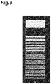
- FIG. 9 shows an example of an X-ray transmission image used for the evaluation of resolution. In this X-ray transmission image, a chart whose resolution changes stepwise in one direction is used as an imaging target. The resolution of the X-ray transmission image can be measured using a modulation transfer function (MTF) or a contrast transfer function (CTF).
- MTF modulation transfer function
- CTF contrast transfer function
- the selection unit 204 finally selects trained models 206 to be used for the noise removal process of the X-ray transmission image of the target object F from the plurality of trained models 206 stored in the control device 20 on the basis of the image characteristics acquired by the specification unit 202. That is, the selection unit 204 compares the image characteristics specified by the specification unit 202 with the image characteristics specified from the image data used to construct the plurality of trained models 206, and selects a trained model 206 in which both are similar to each other.
- the selection unit 204 selects one trained model 206 constructed by the image data of average energy closest to the value of the average energy of the transmitted X-rays specified by the specification unit 202.
- the selection unit 204 acquires a characteristic graph of thickness and luminance for the image data used to construct the plurality of trained models 206 in the same manner as the method of specification performed by the specification unit 202, and selects trained models 206 constructed by image data having characteristics closest to the characteristic graph of thickness and luminance acquired for the jig as final trained models 206.
- the image characteristics of the image data used to construct the trained models 206 may be referred to those calculated in advance outside the control device 20.
- the selection unit 204 may select trained models 206 constructed by image data having the characteristics of the luminance to noise ratio closest to the characteristics of the luminance to noise ratio acquired by the specification unit 202 as the final trained models 206.
- the image characteristics of the image data used to construct the trained models 206 may be acquired by the selection unit 204 from the image data, or may be referred to those calculated in advance outside the control device 20.
- the selection unit 204 may select the trained model 206 using the characteristics of luminance and noise, as the noise characteristics, instead of the characteristics of the luminance to noise ratio.
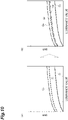
- FIG. 10 is a diagram illustrating a function of selection of a trained model based on image characteristics which is performed by the selection unit 204.
- the part (a) shows characteristic graphs G 1 , G 2 , and G 3 of luminance and SNR of image data used to construct the plurality of trained models 206
- the part (b) shows a characteristic graph G T of luminance and SNR of the X-ray transmission image obtained by capturing an image of the jig in addition to these characteristic graphs G 1 , G 2 , and G 3 .
- the selection unit 204 functions so as to select trained models 206 constructed by image data of the characteristic graph G 2 closest to the characteristics of the characteristic graph G T .
- the selection unit 204 calculates an SNR error for each luminance value at regular intervals between each of the characteristic graphs G 1 , G 2 , and G 3 and the characteristic graph G T , calculates the root mean squared error (RMSE) of these errors, and selects trained models 206 corresponding to the characteristic graphs G 1 , G 2 , and G 3 having the smallest root mean squared error.
- RMSE root mean squared error
- the selection unit 204 can select trained models 206 in the same way.
- the selection unit 204 can also select trained models 206 used to generate an image having relatively excellent characteristics on the basis of the characteristics of an image after a plurality of trained models are applied to the X-ray transmission image of the jig and the noise removal process is executed.
- the selection unit 204 uses the X-ray transmission image obtained by capturing an image of the jig having charts of various resolutions to apply a plurality of trained models 206 to the image and evaluate the resolution characteristics of the resulting image after noise removal. The selection unit 204 then selects trained model 206 used for an image having the smallest change in the resolution of each distribution before and after the noise removal process.
- the selection unit 204 may evaluate the characteristics of the luminance to noise ratio of the image after noise removal and select trained model 206 used to generate an image having the highest characteristics.
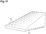
- FIG. 11 shows an example of the structure of the jig used for the evaluation of the luminance to noise ratio.
- a jig in which foreign substances P2 having various materials and various sizes are scattered in a member P1 whose thickness changes stepwise in one direction can be used.
- FIG. 12 shows an X-ray transmission image obtained for the jig of FIG. 11 after the noise removal process.
- the selection unit 204 selects an image region R1 containing an image of the foreign substance P2 in the X-ray transmission image and an image region R2 not containing an image of the foreign substance P2 in the vicinity of the region R1, and calculates the minimum value L MIN of luminance in the image region R1, the average value L AVE of luminance in the image region R2, and the standard deviation L SD of luminance in the image region R2.
- the selection unit 204 calculates the luminance to noise ratio CNR using the following expression.
- CNR L AVE ⁇ L MIN / L SD
- the selection unit 204 calculates the luminance to noise ratio CNR for each of the X-ray transmission images after the application of the plurality of trained models 206, and selects trained models 206 used to generate an X-ray transmission image having the highest luminance to noise ratio CNR.
- the selection unit 204 may perform the calculation using the following expression on the basis of the average value L AVE_R1 of luminance in the image region R1, the average value L AVE_R2 of luminance in the image region R2, and the standard deviation L SD of luminance in the image region R2.
- CNR L AVE _ R 1 ⁇ L MIN _ R 2 / L SD
- the processing unit 205 applies the trained models 206 selected by the selection unit 204 to the X-ray transmission image acquired for the target object F, and generates an output image by executing image processing for removing noise. The processing unit 205 then outputs the generated output image to the display device 30 or the like.
- FIG. 13 is a flowchart illustrating a procedure of observation processing using the image acquisition device 1.
- an operator (user) of the image acquisition device 1 sets the imaging conditions in the image acquisition device 1 such as the tube voltage of the X-ray irradiator 50 or the gain in the X-ray detection camera 10 (step S1).
- a jig is set in the image acquisition device 1, and the control device 20 acquires an X-ray transmission image for the jig (step S2).
- X-ray transmission images of a plurality of types of jigs may be sequentially acquired.
- control device 20 specifies the image characteristics (energy characteristics, noise characteristics, and resolution characteristics) of the X-ray transmission image of the jig (step S3). Further, the control device 20 applies a plurality of trained models 206 to the X-ray transmission image of the jig, and specifies the image characteristics (such as the resolution characteristics or the value of the luminance to noise ratio) of each X-ray transmission image after the application of the plurality of trained models 206 (step S4).
- the control device 20 selects trained model 206 on the basis of the result of comparison between the energy characteristics of the X-ray transmission image of the jig and the energy characteristics of the image data used to construct the trained model 206, and the degree of change in the resolution characteristics of the X-ray transmission image of the jig before and after the application of the trained model (step S5).
- the trained model 206 may be selected on the basis of the result of comparison between the noise characteristics of the X-ray transmission image of the jig and the noise characteristics of the image data used to construct trained model 206, and the state of change in the resolution characteristics of the X-ray transmission image of the jig before and after the application of the trained model.
- a trained model 206 having the highest luminance to noise ratio CNR after the application of the trained model of the X-ray transmission image of the jig may be selected instead of the above process.
- the target object F is set to capture an image of the target object F, and thus an X-ray transmission image of the target object F is acquired (step S7).
- the control device 20 applies the finally selected trained model 206 to the X-ray transmission image of the target object F, and thus the noise removal process is executed for the X-ray transmission image (step S8).
- the control device 20 outputs an output image which is an X-ray transmission image that has undergone the noise removal process to the display device 30 (step S9).
- the image characteristics of the X-ray transmission image of the jig are specified, and a trained model used for noise removal is selected from the trained models constructed in advance on the basis of the image characteristics.
- an X-ray transmission image contains noise derived from the generation of X-rays. It is also conceivable to increase the X-ray dose in order to improve the SN ratio of the X-ray transmission image. However, in that case, there is a problem in that increasing the X-ray dose increases the exposure of a sensor, shortens the life of the sensor, and shortens the life of the X-ray source, and thus it is difficult to achieve both an improvement in the SN ratio and an increase in life. In the present embodiment, it is not necessary to increase the X-ray dose, and thus it is possible to achieve both an improvement in the SN ratio and an increase in life.
- the image characteristics of the X-ray transmission image of the jig and the image characteristics of the image data used to construct the trained model are compared with each other. Therefore, since the trained model 206 constructed by the image data corresponding to the image characteristics of the X-ray transmission image of the jig is selected, it is possible to effectively remove noise from the X-ray transmission image of the target object F.
- the trained model is selected using the image characteristics of an image in which a plurality of trained models 206 are applied to the X-ray transmission image of the jig.
- the trained model 206 is selected on the basis of the image characteristics of the X-ray transmission image of the jig to which a plurality of trained models 206 are actually applied, it is possible to effectively remove noise from the X-ray transmission image of the target object F.
- energy characteristics or noise characteristics are used as the image characteristics.
- the trained model 206 constructed by an image having characteristics similar to the energy characteristics or noise characteristics of the X-ray transmission image of the jig changing depending on the imaging conditions of the image acquisition device 1 is selected. As a result, it is possible to remove noise from the X-ray transmission image of the target object F corresponding to a change in the conditions of the image acquisition device 1.
- resolution characteristics or luminance to noise ratio are also used as the image characteristics.
- the selected trained model 206 is applied, and thus it is possible to obtain an X-ray transmission image having good resolution characteristics or luminance to noise ratio. As a result, it is possible to remove noise from the X-ray transmission image of the target object corresponding to a change in the conditions of the image acquisition device 1.
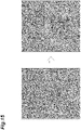
- FIGS. 14 and 15 show examples of X-ray transmission images acquired by the image acquisition device 1 before and after the noise removal process.
- FIGS. 14 and 15 show an image of cheese to which foreign substances such as metal or glass are added and an image of chicken in which bones of various sizes remain, respectively, and show an image before noise processing on the left side and an image after noise processing on the right side, respectively. In this manner, according to the present embodiment, it can be understood that noise removal is effectively performed on various target objects.
- the X-ray detection camera 10 has been described as a dual-line X-ray camera, the camera is not limited thereto, and may be a single line X-ray camera, a dual energy X-ray camera, a time delay integration (TDI) scan X-ray camera, a multi-line X-ray camera having a plurality of two or more lines, a two-dimensional X-ray camera, an X-rays flat panel sensor, an X-rays I.I, a direct conversion type X-ray camera (a-Se, Si, CdTe, CdZnTe, TIBr, PbI2, or the like) that does not uses a scintillator, or an observation type camera using an optical lens with a scintillator based on lens coupling.
- the X-ray detection camera 10 may be a camera tube sensitive to radiation or a point sensor sensitive to radiation.
- the image acquisition device 1 is not also limited to the above embodiment, and may be a radiographic image processing system such as a computed tomography (CT) device that captured an image of the target object F in a stationary state. Further, the image acquisition device may be a radiographic image processing system that captures an image of the target object F while rotating the target object.
- CT computed tomography
- jigs in the image acquisition device 1 of the above embodiment, various types of jigs can be used.
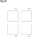
- a jig in which flat plate-like members P11, P12, P13, and P14 made of different materials are arranged two-dimensionally may be used.
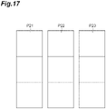
- a form in which members having a shape whose thickness changes one-dimensionally stepwise, that is, flat plate-like members P21, P22, and P23 whose materials are different from each other are arranged side by side may be used.
- a portion of a jig may have an opening or cut shape so that the target object F or that similar to the target object F can be imaged during capture of an image of the jig.
- the target object F may be imaged during capture of an image of the jig, and a trained model may be selected by combining a transmitted image of the target object with a transmitted image of the jig.
- a jig having a chart disposed so that the boundary line faces in a parallel direction, a diagonal direction, or a vertical direction with respect to the transport direction TD of the belt conveyor 60 may be used.
- the step of selecting includes selecting the trained model by comparing the image characteristics with image characteristics specified from the image data.
- the selection unit selects the trained model by comparing the image characteristics with image characteristics specified from the image data.
- the step of specifying includes specifying image characteristics of a plurality of images obtained as a result of applying the plurality of trained models to the radiographic image of the jig, and that the step of selecting includes selecting the trained model on the basis of the image characteristics of the plurality of images.
- the specification unit specifies image characteristics of a plurality of images obtained as a result of applying the plurality of trained models to the radiographic image of the jig, and that the selection unit selects the trained model on the basis of the image characteristics of the plurality of images. In this case, since the trained model is selected on the basis of the image characteristics of the radiographic image of the jig to which a plurality of trained models are actually applied, it is possible to effectively remove noise from the radiographic image of the target object.
- the image characteristics are at least one of energy characteristics, noise characteristics, and frequency characteristics
- the step of selecting includes selecting the trained model constructed by image data image characteristics of which are similar to the image characteristics.
- the image characteristics are at least one of energy characteristics, noise characteristics, and frequency characteristics
- the selection unit selects the trained model constructed by image data image characteristics of which are similar to the image characteristics.
- the trained model constructed by an image having characteristics similar to at least one of the energy characteristics, noise characteristics, and frequency characteristics of the radiographic image of the jig changing depending on the system is selected. As a result, it is possible to remove noise from the radiographic image of the target object corresponding to a change in the conditions of the system.
- the image characteristics are resolution characteristics or a luminance to noise ratio
- the step of selecting further includes selecting the trained model used to generate an image having relatively excellent resolution characteristics or luminance to noise ratio.
- the image characteristics are resolution characteristics or a luminance to noise ratio
- the selection unit selects the trained model used to generate an image having relatively excellent resolution characteristics or luminance to noise ratio. According to such a configuration, the selected trained model is applied, and thus it is possible to obtain a radiographic image having good resolution characteristics or luminance to noise ratio. As a result, it is possible to remove noise from the radiographic image of the target object corresponding to a change in the conditions of the system.
- the embodiment uses a radiographic image processing method, a trained model, a radiographic image processing module, a radiographic image processing program, and a radiographic image processing system, thereby allowing noise in a radiographic image to be effectively removed.
Landscapes
- Physics & Mathematics (AREA)
- General Physics & Mathematics (AREA)
- Health & Medical Sciences (AREA)
- Engineering & Computer Science (AREA)
- Life Sciences & Earth Sciences (AREA)
- General Health & Medical Sciences (AREA)
- Theoretical Computer Science (AREA)
- Chemical & Material Sciences (AREA)
- Immunology (AREA)
- Pathology (AREA)
- Biochemistry (AREA)
- Analytical Chemistry (AREA)
- Toxicology (AREA)
- Software Systems (AREA)
- Molecular Biology (AREA)
- Computer Vision & Pattern Recognition (AREA)
- Artificial Intelligence (AREA)
- Mathematical Physics (AREA)
- General Engineering & Computer Science (AREA)
- Data Mining & Analysis (AREA)
- Evolutionary Computation (AREA)
- Computing Systems (AREA)
- High Energy & Nuclear Physics (AREA)
- Spectroscopy & Molecular Physics (AREA)
- Computational Linguistics (AREA)
- Biomedical Technology (AREA)
- Biophysics (AREA)
- Medical Informatics (AREA)
- Quality & Reliability (AREA)
- Analysing Materials By The Use Of Radiation (AREA)
- Image Processing (AREA)
- Apparatus For Radiation Diagnosis (AREA)
Abstract
Description
- One aspect of an embodiment relates to a radiographic image processing method, a trained model, a radiographic image processing module, a radiographic image processing program, and a radiographic image processing system.
- Since the past, a method of removing noise from image data using a trained model through machine learning such as deep learning has been known (see, for example, the following Patent Literature 1). According to this method, noise from the image data is automatically removed, and thus it is possible to observe a target object with high accuracy.
- [Patent Literature 1]
Japanese Unexamined Patent Publication No. 2019-91393 - In the method of the related art as described above, noise may not be sufficiently removed in a case where a radiographic image generated by transmitting radiation such as X-rays through a target object is used as a target. For example, a relationship between luminance and noise in an image has a tendency to fluctuate depending on the conditions of a radiation source such as an X-ray source, the type of filter being used, and the like, and the noise tends to be difficult to remove effectively.
- Consequently, one aspect of an embodiment was contrived in view of such a problem, and an object thereof is to provide a radiographic image processing method, a trained model, a radiographic image processing module, a radiographic image processing program, and a radiographic image processing system that make it possible to effectively remove noise from a radiographic image.
- According to one aspect of an embodiment, there is provided a radiographic image processing method including: a step of acquiring a radiographic image of a jig using a system that radiates radiation to a target object and captures an image of the radiation passing through the target object to acquire a radiographic image; a step of specifying image characteristics of the radiographic image of the jig; a step of selecting a trained model on the basis of the image characteristics from a plurality of trained models constructed through machine learning in advance using image data; a step of acquiring a radiographic image of the target object using the system; and a step of executing image processing for removing noise from the radiographic image of the target object using the selected trained model.
- Alternatively, according to another aspect of the embodiment, there is provided a trained model used for the above radiographic image processing method, wherein the trained model is constructed through machine learning using image data and causes a processor to execute image processing for removing noise from a radiographic image of the target object.
- Alternatively, according to another aspect of the embodiment, there is provided a radiographic image processing module including: an acquisition unit configured to acquire radiographic images of a jig and a target object using a system that radiates radiation to the target object and captures an image of the radiation passing through the target object to acquire a radiographic image; a specification unit configured to specify image characteristics of the radiographic image of the jig; a selection unit configured to select a trained model on the basis of the image characteristics from a plurality of trained models constructed through machine learning in advance using image data; and a processing unit configured to execute image processing for removing noise from the radiographic image of the target object using the selected trained model.
- Alternatively, according to another aspect of the embodiment, there is provided a radiographic image processing program causing a processor to function as: an acquisition unit configured to acquire radiographic images of a jig and a target object using a system that radiates radiation to the target object and captures an image of the radiation passing through the target object to acquire a radiographic image; a specification unit configured to specify image characteristics of the radiographic image of the jig; a selection unit configured to select a trained model on the basis of the image characteristics from a plurality of trained models constructed through machine learning in advance using image data; and a processing unit configured to execute image processing for removing noise from the radiographic image of the target object using the selected trained model.
- Alternatively, according to another aspect of the embodiment, there is provided a radiographic image processing system including: the above radiographic image processing module; a source configured to radiate radiation to the target object; and an imaging device configured to capture an image of the radiation passing through the target object and acquire the radiographic image.
- According to the one aspect or the other aspects, the image characteristics of the radiographic image of the jig are specified, and the trained model used for noise removal is selected from the trained models constructed in advance on the basis of the image characteristics. Thereby, since the characteristics of the radiographic image changing depending on the conditions and the like of the radiation source in the system can be estimated, and the trained model selected in accordance with the estimation result is used for noise removal, it is possible to realize noise removal corresponding to the relationship between luminance and noise in the radiographic image. As a result, it is possible to effectively remove noise from the radiographic image.
- According to the embodiment, it is possible to effectively remove noise from a radiographic image of a target object.
-
-
FIG. 1 is a schematic configuration diagram of animage acquisition device 1 according to an embodiment. -
FIG. 2 is a block diagram illustrating an example of a hardware configuration of acontrol device 20 ofFIG. 1 . -
FIG. 3 is a block diagram illustrating a functional configuration of thecontrol device 20 ofFIG. 1 . -
FIG. 4 is a diagram illustrating an example of image data which is training data used to construct trainedmodels 206 ofFIG. 3 . -
FIG. 5 is a flowchart illustrating a procedure of creating image data which is training data used to construct the trainedmodels 206 ofFIG. 3 . -
FIG. 6 is a diagram illustrating an example of an X-ray transmission image to be analyzed by aspecification unit 202 ofFIG. 3 . -
FIG. 7 is a diagram illustrating an example of a characteristic graph of thickness and luminance acquired by thespecification unit 202 ofFIG. 3 . -
FIG. 8 is a diagram illustrating an example of a characteristic graph of luminance and SNR acquired by thespecification unit 202 ofFIG. 3 . -
FIG. 9 is a diagram illustrating an example of an X-ray transmission image used for the evaluation of resolution in thespecification unit 202 ofFIG. 3 . -
FIG. 10 is a diagram illustrating a function of selection of a trained model based on image characteristics which is performed by aselection unit 204 ofFIG. 3 . -
FIG. 11 is a perspective view illustrating an example of a structure of a jig used for the evaluation of a luminance to noise ratio which is performed by theselection unit 204 ofFIG. 3 . -
FIG. 12 is a diagram illustrating an X-ray transmission image after a noise removal process obtained for the jig ofFIG. 11 . -
FIG. 13 is a flowchart illustrating a procedure of observation processing using theimage acquisition device 1. -
FIG. 14 is a diagram illustrating an example of an X-ray transmission image acquired by theimage acquisition device 1 before and after the noise removal process. -
FIG. 15 is a diagram illustrating an example of an X-ray transmission image acquired by theimage acquisition device 1 before and after the noise removal process. -
FIG. 16 is a plan view illustrating a form of a jig used in theimage acquisition device 1. -
FIG. 17 is a plan view illustrating a form of the jig used in theimage acquisition device 1. -
FIG. 18 is a plan view illustrating a form of the jig used in theimage acquisition device 1. - Hereinafter, embodiments of the present invention will be described in detail with reference to the accompanying drawings. Meanwhile, in the description, the same elements or elements having the same function are denoted by the same reference signs, and thus duplicate description will be omitted.
-
FIG. 1 is a configuration diagram of animage acquisition device 1 which is a radiographic image processing system according to the present embodiment. As shown inFIG. 1 , theimage acquisition device 1 is a device that radiates X-rays (radiation) to a target object F which is transported in a transport direction TD and acquires an X-ray transmission image (radiographic image) obtained by capturing an image of the target object F on the basis of the X-rays passing through the target object F. Theimage acquisition device 1 performs a foreign substance inspection, a weight inspection, a product inspection, or the like on the target object F using an X-ray transmission image, and examples of the application include food inspection, baggage inspection, substrate inspection, battery inspection, material inspection, and the like. Theimage acquisition device 1 is configured to include a belt conveyor (transport means) 60, an X-ray irradiator (radiation source) 50, an X-ray detection camera (imaging device) 10, a control device (radiographic image processing module) 20, adisplay device 30, and aninput device 40 for performing various inputs. Meanwhile, the radiographic image in the embodiment of the present invention is not limited to an X-ray image, and may also be an image caused by electromagnetic radiation other than X-rays such as γ-rays. - The
belt conveyor 60 has a belt portion on which the target object F is placed, and transports the target object F in the transport direction TD at a predetermined transport speed by moving the belt portion in the transport direction TD. The transport speed of the target object F is, for example, 48 m/min. Thebelt conveyor 60 can change the transport speed as necessary to a transport speed such as, for example, 24 m/min or 96 m/min. In addition, thebelt conveyor 60 can appropriately change the height position of the belt portion to change a distance between theX-ray irradiator 50 and the target object F. Meanwhile, examples of the target object F transported by thebelt conveyor 60 include foodstuffs such as meat, seafood, agricultural products, or confectionery, rubber products such as tires, resin products, metal products, resource materials such as minerals, waste, and various products such as electronic parts or electronic substrates. TheX-ray irradiator 50 is a device that radiates (outputs) X-rays to the target object F as an X-ray source. TheX-ray irradiator 50 is a point light source, and diffuses and radiates the X-rays in a predetermined angle range in a fixed irradiation direction. TheX-ray irradiator 50 is disposed above thebelt conveyor 60 at a predetermined distance from thebelt conveyor 60 so that the irradiation direction of the X-rays is directed toward thebelt conveyor 60 and the diffused X-rays extend in the entire width direction of the target object F (a direction intersecting the transport direction TD). In addition, theX-ray irradiator 50 is configured such that, in the lengthwise direction of the target object F (a direction parallel to the transport direction TD), a predetermined division range in the lengthwise direction is set as an irradiation range, and the X-rays are radiated in the entire lengthwise direction of the target object F by the target object F being transported in the transport direction TD by thebelt conveyor 60. TheX-ray irradiator 50 has a tube voltage and a tube current set by thecontrol device 20, and radiates X-rays having predetermined energy and a radiation dose according to the set tube voltage and tube current toward thebelt conveyor 60. In addition, afilter 51 that transmits a predetermined wavelength region of the X-rays is provided in the vicinity of theX-ray irradiator 50 on thebelt conveyor 60 side. Thefilter 51 is not necessarily required and may not be present. - The
X-ray detection camera 10 detects X-rays passing through the target object F among the X-rays radiated to the target object F by theX-ray irradiator 50, and outputs a signal based on the X-rays. TheX-ray detection camera 10 is a dual-line X-ray camera in which two sets of configurations for detecting X-rays are disposed. In theimage acquisition device 1 according to the present embodiment, each X-ray transmission image is generated on the basis of the X-rays detected in each line (a first line and a second line) of the dual-line X-ray camera. By performing average processing, addition processing, or the like on the two generated X-ray transmission images, a clear (high-luminance) image can be acquired with a smaller X-ray dose than in a case where an X-ray transmission image is generated on the basis of the X-rays detected in one line. - The
X-ray detection camera 10 includes afilter 19,scintillators 11a and 11b,line scan cameras sensor control unit 13,amplifiers AD converters correction circuits output interfaces amplifier control unit 18. The scintillator 11a, theline scan camera 12a, theamplifier 14a, theAD converter 15a, thecorrection circuit 16a, and theoutput interface 17a are electrically connected to each other, and have components related to the first line. In addition, thescintillator 11b, theline scan camera 12b, theamplifier 14b, theAD converter 15b, thecorrection circuit 16b, and theoutput interface 17b are electrically connected to each other, and have components related to the second line. Theline scan camera 12a of the first line and theline scan camera 12b of the second line are disposed side by side in the transport direction TD. Meanwhile, hereinafter, the components of the first line will be described to represent components common to the first line and the second line. - The scintillator 11a is fixed on the
line scan camera 12a by adhesion or the like, and converts the X-rays passing through the target object F into scintillation light. The scintillator 11a outputs the scintillation light to theline scan camera 12a. Thefilter 19 transmits a predetermined wavelength region of the X-rays toward the scintillator 11a. Thefilter 19 is not necessarily required and may not be present. - The
line scan camera 12a detects the scintillation light from the scintillator 11a, converts the detected light into electric charge, and outputs it as a detection signal (electrical signal) to theamplifier 14a. Theline scan camera 12a has a plurality of line sensors arranged in parallel in a direction intersecting the transport direction TD. The line sensor is, for example, a charge coupled device (CCD) image sensor, a complementary metal-oxide semiconductor (CMOS) image sensor, or the like, and includes a plurality of photodiodes. - The
sensor control unit 13 controls theline scan cameras line scan cameras line scan cameras line scan cameras belt conveyor 60, the distance between theX-ray irradiator 50 and the target object F on the belt conveyor 60 (focus object distance (FOD)), and the distance between theX-ray irradiator 50 and theline scan cameras line scan cameras line scan cameras line scan cameras belt conveyor 60, the distance between theX-ray irradiator 50 and the target object F on the belt conveyor 60 (FOD), and the distance between theX-ray irradiator 50 and theline scan cameras amplifier 14a amplifies the detection signal at a predetermined set amplification factor to generate an amplified signal, and outputs the amplified signal to theAD converter 15a. The set amplification factor is an amplification factor which is set by theamplifier control unit 18. Theamplifier control unit 18 sets the set amplification factor of theamplifiers - The
AD converter 15a converts the amplified signal (voltage signal) output by theamplifier 14a into a digital signal, and outputs the converted signal to thecorrection circuit 16a. Thecorrection circuit 16a performs a predetermined correction such as signal amplification on the digital signal, and outputs the corrected digital signal to theoutput interface 17a. Theoutput interface 17a outputs the digital signal to the outside of theX-ray detection camera 10. InFIG. 1 , the AD converter, the correction circuit, and the output interface exist individually, but they may be integrated into one. - The
control device 20 is a computer such as, for example, a personal computer (PC). Thecontrol device 20 generates an X-ray transmission image on the basis of the digital signal (amplified signal) output from the X-ray detection camera 10 (more specifically, theoutput interfaces control device 20 generates one X-ray transmission image by performing average processing or addition processing on two digital signals output from theoutput interfaces display device 30 after a noise removal process to be described later is performed, and is displayed by thedisplay device 30. In addition, thecontrol device 20 controls theX-ray irradiator 50, theamplifier control unit 18, and thesensor control unit 13. Meanwhile, thecontrol device 20 of the present embodiment is a device which is independently provided outside theX-ray detection camera 10, but it may be integrated inside theX-ray detection camera 10. -
FIG. 2 shows a hardware configuration of thecontrol device 20. As shown inFIG. 2 , thecontrol device 20 is a computer or the like physically including a central processing unit (CPU) 101 which is a processor, a random access memory (RAM) 102 or a read only memory (ROM) 103 which is a recording medium, acommunication module 104, an input andoutput module 106, and the like, which are electrically connected to each other. Meanwhile, thecontrol device 20 may include a display, a keyboard, a mouse, a touch panel display, and the like as theinput device 40 and thedisplay device 30, or may include a data recording device such as a hard disk drive or a semiconductor memory. In addition, thecontrol device 20 may be constituted by a plurality of computers. -
FIG. 3 is a block diagram illustrating a functional configuration of thecontrol device 20. Thecontrol device 20 includes anacquisition unit 201, aspecification unit 202, aselection unit 204, and aprocessing unit 205. Each functional unit of thecontrol device 20 shown inFIG. 3 is realized by loading a program (a radiographic image processing program of the present embodiment) on the hardware such as theCPU 101 and theRAM 102 to thereby bring thecommunication module 104, the input andoutput module 106, and the like into operation under the control of theCPU 101 and read out and write data in theRAM 102. TheCPU 101 of thecontrol device 20 causes thecontrol device 20 to function as each functional unit inFIG. 3 by executing this computer program, and sequentially executes processing corresponding to a radiographic image processing method to be described later. Meanwhile, the CPU may be a single piece of hardware, or may be implemented in a programmable logic such as an FPGA like a soft processor. The RAM or the ROM may also be a single piece of hardware, or may be built into a programmable logic such as an FPGA. Various types of data required for executing this computer program and various types of data generated by executing this computer program are all stored in a built-in memory such as theROM 103 or theRAM 102, or a storage medium such as a hard disk drive. - In addition, a plurality of trained
models 206 which are loaded by theCPU 101 to cause theCPU 101 to execute a noise removal process for an X-ray transmission image are stored in advance in thecontrol device 20. Each of the plurality of trainedmodels 206 is a learning model based on machine learning constructed in advance using image data as training data. Examples of machine learning include supervised learning, deep learning, reinforcement learning, neural network learning, and the like. In the present embodiment, the two-dimensional convolutional neural network described in the paper "Beyond a Gaussian Denoiser: Residual Learning of Deep CNN for Image Denoising" authored by Kai Zhang et al. is adopted as an example of a deep learning algorithm. The plurality of trainedmodels 206 may be generated by an external computer or the like and downloaded to thecontrol device 20, or may be generated in thecontrol device 20. -
FIG. 4 shows an example of image data which is training data used to construct trainedmodels 206. As the training data, an X-ray transmission image having a pattern of various thicknesses, various materials, and various resolutions as an imaging target can be used. The example shown inFIG. 4 is an example of an X-ray transmission image generated for chicken. As the image data, an X-ray transmission image actually generated for a plurality of types of target objects using theimage acquisition device 1 may be used, or image data generated by simulation calculation may be used. The X-ray transmission image may be acquired using a device different from theimage acquisition device 1. In addition, the X-ray transmission image and the image data generated by simulation calculation may be used in combination. Each of the plurality of trainedmodels 206 is constructed in advance using image data obtained for transmitted X-rays having different average energy and having a known noise distribution. The average energy of X-rays in the image data is set to a different value in advance by setting the operating conditions of the X-ray irradiator (radiation source) 50 of theimage acquisition device 1, the imaging conditions of theimage acquisition device 1, or the like, or setting the operating conditions or imaging conditions of theX-ray irradiator 50 during simulation calculation. That is, the plurality of trainedmodels 206 are constructed through machine learning using, as training data, a training image which is an X-ray image corresponding to average energy related to X-rays passing through the target object F calculated on the basis of condition information indicating the operating conditions of the X-ray irradiator (radiation source) 50 when the X-ray transmission image of the target object F is captured, the imaging conditions of theX-ray detection camera 10, or the like (construction step). For example, in the present embodiment, each of the plurality of trainedmodels 206 is constructed using multiple frames (for example, 20,000 frames) of a plurality of types of image data in which the average energy is 10 keV, 20 keV, 30 keV, ··· and values in increments of 10 keV are set. -
FIG. 5 is a flowchart illustrating a procedure of creating image data which is training data used to construct the trainedmodels 206. - The image data (also referred to as training image data) which is training data is created by a computer in the following procedure. First, an image of a structural body having a predetermined structure (structure image) is created (step S101). For example, an image of a structural body having a predetermined structure may be created by simulation calculation. In addition, an X-ray image of a structure such as a chart having a predetermined structure may be acquired to create a structure image. Next, a sigma value which is a standard deviation of pixel values is calculated for one pixel selected from a plurality of pixels constituting such a structure image (step S102). A normal distribution (Poisson distribution) indicating a noise distribution is then set on the basis of the sigma value obtained in step S102 (step S103). In this manner, training data for various noise conditions can be generated by setting the normal distribution on the basis of the sigma value. Subsequently, a noise value which is set at random is calculated along the normal distribution which is set on the basis of the sigma value in step S103 (step S104). Further, the noise value obtained in step S104 is added to the pixel value of one pixel to generate pixel values constituting the image data which is training data (step S105). The processes of steps S102 to S105 are performed for each of a plurality of pixels constituting the structure image (step S106), and training image data serving as training data is generated (step S107). In addition, in a case where the training image data is further required, it is determined that the processes of steps S 101 to S107 are performed on another structure image (step S108), and another training image data serving as training data is generated. Meanwhile, the other structure image may be an image of a structural body having the same structure, or may be an image of a structural body having another structure.
- Meanwhile, it is necessary to prepare a large number of pieces of image data which is training data used to construct the trained
model 206. In addition, the structure image is preferably an image with less noise, ideally an image without noise. Therefore, when a structure image is generated through simulation calculation, many images without noise can be generated, and thus it is effective to generate a structure image through simulation calculation. - Hereinafter, referring back to
FIG. 3 , the details of the function of each functional unit of thecontrol device 20 will be described. - The
acquisition unit 201 acquires an X-ray transmission image captured by radiating X-rays to a jig and the target object F using theimage acquisition device 1. As the jig, a flat plate-like member whose thickness and material are known and in which a relationship between the average energy of X-rays and the transmittance of X-rays is known, or a jig having a chart whose image is captured at various resolutions is used. That is, theacquisition unit 201 acquires an X-ray transmission image of the jig captured by using theimage acquisition device 1 in advance of the observation processing of the target object F. Theacquisition unit 201 acquires an X-ray transmission image of the target object F captured by using theimage acquisition device 1 at a timing after the trainedmodel 206 is selected on the basis of the X-ray transmission image of the jig. However, the acquisition timings of the X-ray transmission images of the jig and the target object F are not limited to the above, and may be simultaneous or reverse timings. - The
specification unit 202 specifies the image characteristics of the X-ray transmission image of the jig acquired by theacquisition unit 201. Specifically, theselection unit 204 specifies energy characteristics, noise characteristics, resolution characteristics, frequency characteristics, or the like as the image characteristics of the X-ray transmission image. - For example, in a case where a flat plate-like member whose thickness and material is known is used as a jig, the
specification unit 202 compares the luminance of the X-ray image passing through the jig with the luminance of the X-ray image passing through the air, and calculates the transmittance of X-rays at one point (or the average transmittance of a plurality of points) in the jig. For example, in a case where the luminance of the X-ray image passing through the jig is 5,550 and the luminance of the X-ray image passing through the air is 15,000, the transmittance is calculated to be 37%. Thespecification unit 202 then specifies the average energy (for example, 50 keV) of transmitted X-rays estimated from the transmittance of 37% as the energy characteristics of the X-ray transmission image of the jig. - In addition, the
specification unit 202 may analyze the characteristics at a plurality of points of the jig whose thickness or material changes as the energy characteristics of the X-ray transmission image of the jig.FIG. 6 is a diagram illustrating an example of an X-ray transmission image to be analyzed by thespecification unit 202.FIG. 6 is an X-ray transmission image for a jig having a shape in which the thickness changes stepwise. Thespecification unit 202 selects a plurality of measurement regions (regions of interest (ROI)) having different thicknesses from such an X-ray transmission image, analyzes the luminance average value for each of the plurality of measurement regions, and acquires a characteristic graph of thickness and luminance as energy characteristics.FIG. 7 shows an example of a characteristic graph of thickness and luminance acquired by thespecification unit 202. - In addition, the
specification unit 202 can also analyze the luminance value and noise for each of the plurality of measurement regions as the noise characteristics of the X-ray transmission image of the jig, and acquire a characteristic graph of a luminance to noise ratio as the noise characteristics. That is, thespecification unit 202 selects a plurality of measurement regions ROI having different thicknesses or materials from the X-ray transmission image, analyzes the standard deviation of the luminance values of the plurality of measurement regions ROI and the average value of the luminance values thereof, and acquires a characteristic graph of luminance and a SN ratio (SNR) as the noise characteristics. In this case, thespecification unit 202 calculates the SNR for each measurement region ROI using SNR = (average value of luminance values) ÷ (standard deviation of luminance values).FIG. 8 shows an example of a characteristic graph of luminance and SNR acquired by thespecification unit 202. Here, thespecification unit 202 may acquire a characteristic graph in which the vertical axis is noise calculated from the standard deviation of the luminance values, as the noise characteristics, instead of the above characteristic graph of luminance and SNR. - In addition, in a case where a jig having a chart is used, the
specification unit 202 can also acquire the distribution of resolutions in the X-ray transmission image of the jig as the resolution characteristics. Further, thespecification unit 202 has also a function of acquiring the resolution characteristics of an image after the noise removal process is performed by applying a plurality of trainedmodels 206 to the X-ray transmission image of the jig.FIG. 9 shows an example of an X-ray transmission image used for the evaluation of resolution. In this X-ray transmission image, a chart whose resolution changes stepwise in one direction is used as an imaging target. The resolution of the X-ray transmission image can be measured using a modulation transfer function (MTF) or a contrast transfer function (CTF). - Referring back to
FIG. 3 , theselection unit 204 finally selects trainedmodels 206 to be used for the noise removal process of the X-ray transmission image of the target object F from the plurality of trainedmodels 206 stored in thecontrol device 20 on the basis of the image characteristics acquired by thespecification unit 202. That is, theselection unit 204 compares the image characteristics specified by thespecification unit 202 with the image characteristics specified from the image data used to construct the plurality of trainedmodels 206, and selects a trainedmodel 206 in which both are similar to each other. - For example, the
selection unit 204 selects one trainedmodel 206 constructed by the image data of average energy closest to the value of the average energy of the transmitted X-rays specified by thespecification unit 202. - In addition, the
selection unit 204 acquires a characteristic graph of thickness and luminance for the image data used to construct the plurality of trainedmodels 206 in the same manner as the method of specification performed by thespecification unit 202, and selects trainedmodels 206 constructed by image data having characteristics closest to the characteristic graph of thickness and luminance acquired for the jig as final trainedmodels 206. However, the image characteristics of the image data used to construct the trainedmodels 206 may be referred to those calculated in advance outside thecontrol device 20. By using the image characteristics obtained by setting a plurality of measurement regions in this way, it is possible to select the best trained model for noise removal of the X-ray transmission image of the target object F. Particularly, it is possible to accurately estimate a difference in the X-ray spectrum or a difference in the effect of the filter during measurement of the X-ray transmission image. - In addition, the
selection unit 204 may select trainedmodels 206 constructed by image data having the characteristics of the luminance to noise ratio closest to the characteristics of the luminance to noise ratio acquired by thespecification unit 202 as the final trainedmodels 206. However, the image characteristics of the image data used to construct the trainedmodels 206 may be acquired by theselection unit 204 from the image data, or may be referred to those calculated in advance outside thecontrol device 20. Here, theselection unit 204 may select the trainedmodel 206 using the characteristics of luminance and noise, as the noise characteristics, instead of the characteristics of the luminance to noise ratio. By using such characteristics of luminance and noise, it is possible to specify a dominant noise factor (such as shot noise or readout noise) from the slope of the graph in the region of each signal amount with respect to each signal amount detected by theX-ray detection camera 10, and to select trainedmodels 206 on the basis of the specification result. -
FIG. 10 is a diagram illustrating a function of selection of a trained model based on image characteristics which is performed by theselection unit 204. InFIG. 10 , the part (a) shows characteristic graphs G1, G2, and G3 of luminance and SNR of image data used to construct the plurality of trainedmodels 206, and the part (b) shows a characteristic graph GT of luminance and SNR of the X-ray transmission image obtained by capturing an image of the jig in addition to these characteristic graphs G1, G2, and G3. In a case where such characteristic graphs G1, G2, G3, and GT are targeted, theselection unit 204 functions so as to select trainedmodels 206 constructed by image data of the characteristic graph G2 closest to the characteristics of the characteristic graph GT. At the time of selection, theselection unit 204 calculates an SNR error for each luminance value at regular intervals between each of the characteristic graphs G1, G2, and G3 and the characteristic graph GT, calculates the root mean squared error (RMSE) of these errors, and selects trainedmodels 206 corresponding to the characteristic graphs G1, G2, and G3 having the smallest root mean squared error. In addition, even in a case where the selection is performed using the energy characteristics, theselection unit 204 can select trainedmodels 206 in the same way. - The
selection unit 204 can also select trainedmodels 206 used to generate an image having relatively excellent characteristics on the basis of the characteristics of an image after a plurality of trained models are applied to the X-ray transmission image of the jig and the noise removal process is executed. - For example, the
selection unit 204 uses the X-ray transmission image obtained by capturing an image of the jig having charts of various resolutions to apply a plurality of trainedmodels 206 to the image and evaluate the resolution characteristics of the resulting image after noise removal. Theselection unit 204 then selects trainedmodel 206 used for an image having the smallest change in the resolution of each distribution before and after the noise removal process. - In addition to the evaluation of the above change in resolution, the
selection unit 204 may evaluate the characteristics of the luminance to noise ratio of the image after noise removal and select trainedmodel 206 used to generate an image having the highest characteristics.FIG. 11 shows an example of the structure of the jig used for the evaluation of the luminance to noise ratio. For example, as the jig, a jig in which foreign substances P2 having various materials and various sizes are scattered in a member P1 whose thickness changes stepwise in one direction can be used.FIG. 12 shows an X-ray transmission image obtained for the jig ofFIG. 11 after the noise removal process. Theselection unit 204 selects an image region R1 containing an image of the foreign substance P2 in the X-ray transmission image and an image region R2 not containing an image of the foreign substance P2 in the vicinity of the region R1, and calculates the minimum value LMIN of luminance in the image region R1, the average value LAVE of luminance in the image region R2, and the standard deviation LSD of luminance in the image region R2. Theselection unit 204 calculates the luminance to noise ratio CNR using the following expression.
- Further, the
selection unit 204 calculates the luminance to noise ratio CNR for each of the X-ray transmission images after the application of the plurality of trainedmodels 206, and selects trainedmodels 206 used to generate an X-ray transmission image having the highest luminance to noise ratio CNR. - Alternatively, the
selection unit 204 may perform the calculation using the following expression on the basis of the average value LAVE_R1 of luminance in the image region R1, the average value LAVE_R2 of luminance in the image region R2, and the standard deviation LSD of luminance in the image region R2.
- The
processing unit 205 applies the trainedmodels 206 selected by theselection unit 204 to the X-ray transmission image acquired for the target object F, and generates an output image by executing image processing for removing noise. Theprocessing unit 205 then outputs the generated output image to thedisplay device 30 or the like. - Next, a procedure of observing the X-ray transmission image of the target object F using the
image acquisition device 1 according to the present embodiment, that is, a flow of the radiographic image processing method according to the present embodiment will be described.FIG. 13 is a flowchart illustrating a procedure of observation processing using theimage acquisition device 1. - First, an operator (user) of the
image acquisition device 1 sets the imaging conditions in theimage acquisition device 1 such as the tube voltage of theX-ray irradiator 50 or the gain in the X-ray detection camera 10 (step S1). Next, a jig is set in theimage acquisition device 1, and thecontrol device 20 acquires an X-ray transmission image for the jig (step S2). In this case, X-ray transmission images of a plurality of types of jigs may be sequentially acquired. - Accordingly, the
control device 20 specifies the image characteristics (energy characteristics, noise characteristics, and resolution characteristics) of the X-ray transmission image of the jig (step S3). Further, thecontrol device 20 applies a plurality of trainedmodels 206 to the X-ray transmission image of the jig, and specifies the image characteristics (such as the resolution characteristics or the value of the luminance to noise ratio) of each X-ray transmission image after the application of the plurality of trained models 206 (step S4). - Next, the
control device 20 selects trainedmodel 206 on the basis of the result of comparison between the energy characteristics of the X-ray transmission image of the jig and the energy characteristics of the image data used to construct the trainedmodel 206, and the degree of change in the resolution characteristics of the X-ray transmission image of the jig before and after the application of the trained model (step S5). Here, the trainedmodel 206 may be selected on the basis of the result of comparison between the noise characteristics of the X-ray transmission image of the jig and the noise characteristics of the image data used to construct trainedmodel 206, and the state of change in the resolution characteristics of the X-ray transmission image of the jig before and after the application of the trained model. In addition, in step S5, a trainedmodel 206 having the highest luminance to noise ratio CNR after the application of the trained model of the X-ray transmission image of the jig may be selected instead of the above process. - Further, in the
image acquisition device 1, the target object F is set to capture an image of the target object F, and thus an X-ray transmission image of the target object F is acquired (step S7). Next, thecontrol device 20 applies the finally selected trainedmodel 206 to the X-ray transmission image of the target object F, and thus the noise removal process is executed for the X-ray transmission image (step S8). Finally, thecontrol device 20 outputs an output image which is an X-ray transmission image that has undergone the noise removal process to the display device 30 (step S9). - According to the
image acquisition device 1 described above, the image characteristics of the X-ray transmission image of the jig are specified, and a trained model used for noise removal is selected from the trained models constructed in advance on the basis of the image characteristics. Thereby, since the characteristics of the X-ray transmission image changing depending on the operating conditions and the like of theX-ray irradiator 50 in theimage acquisition device 1 can be estimated, and the trainedmodel 206 selected in accordance with the estimation result is used for noise removal, it is possible to realize noise removal corresponding to the relationship between luminance and noise in the X-ray transmission image. As a result, it is possible to effectively remove noise from the X-ray transmission image. - Generally, an X-ray transmission image contains noise derived from the generation of X-rays. It is also conceivable to increase the X-ray dose in order to improve the SN ratio of the X-ray transmission image. However, in that case, there is a problem in that increasing the X-ray dose increases the exposure of a sensor, shortens the life of the sensor, and shortens the life of the X-ray source, and thus it is difficult to achieve both an improvement in the SN ratio and an increase in life. In the present embodiment, it is not necessary to increase the X-ray dose, and thus it is possible to achieve both an improvement in the SN ratio and an increase in life.
- In the present embodiment, in the selection of the trained model, the image characteristics of the X-ray transmission image of the jig and the image characteristics of the image data used to construct the trained model are compared with each other. Thereby, since the trained
model 206 constructed by the image data corresponding to the image characteristics of the X-ray transmission image of the jig is selected, it is possible to effectively remove noise from the X-ray transmission image of the target object F. - In addition, in the present embodiment, the trained model is selected using the image characteristics of an image in which a plurality of trained
models 206 are applied to the X-ray transmission image of the jig. In this case, since the trainedmodel 206 is selected on the basis of the image characteristics of the X-ray transmission image of the jig to which a plurality of trainedmodels 206 are actually applied, it is possible to effectively remove noise from the X-ray transmission image of the target object F. - Particularly, in the present embodiment, energy characteristics or noise characteristics are used as the image characteristics. In this case, the trained
model 206 constructed by an image having characteristics similar to the energy characteristics or noise characteristics of the X-ray transmission image of the jig changing depending on the imaging conditions of theimage acquisition device 1 is selected. As a result, it is possible to remove noise from the X-ray transmission image of the target object F corresponding to a change in the conditions of theimage acquisition device 1. - In the present embodiment, resolution characteristics or luminance to noise ratio are also used as the image characteristics. According to such a configuration, the selected trained
model 206 is applied, and thus it is possible to obtain an X-ray transmission image having good resolution characteristics or luminance to noise ratio. As a result, it is possible to remove noise from the X-ray transmission image of the target object corresponding to a change in the conditions of theimage acquisition device 1. -
FIGS. 14 and15 show examples of X-ray transmission images acquired by theimage acquisition device 1 before and after the noise removal process.FIGS. 14 and15 show an image of cheese to which foreign substances such as metal or glass are added and an image of chicken in which bones of various sizes remain, respectively, and show an image before noise processing on the left side and an image after noise processing on the right side, respectively. In this manner, according to the present embodiment, it can be understood that noise removal is effectively performed on various target objects. - Hereinbefore, although various embodiments of the present invention have been described, the present invention is not limited to the above embodiments, and may be modified or applied to others without changing the gist described in each claim.
- For example, although the
X-ray detection camera 10 has been described as a dual-line X-ray camera, the camera is not limited thereto, and may be a single line X-ray camera, a dual energy X-ray camera, a time delay integration (TDI) scan X-ray camera, a multi-line X-ray camera having a plurality of two or more lines, a two-dimensional X-ray camera, an X-rays flat panel sensor, an X-rays I.I, a direct conversion type X-ray camera (a-Se, Si, CdTe, CdZnTe, TIBr, PbI2, or the like) that does not uses a scintillator, or an observation type camera using an optical lens with a scintillator based on lens coupling. In addition, theX-ray detection camera 10 may be a camera tube sensitive to radiation or a point sensor sensitive to radiation. - In addition, the
image acquisition device 1 is not also limited to the above embodiment, and may be a radiographic image processing system such as a computed tomography (CT) device that captured an image of the target object F in a stationary state. Further, the image acquisition device may be a radiographic image processing system that captures an image of the target object F while rotating the target object. - In addition, in the
image acquisition device 1 of the above embodiment, various types of jigs can be used. For example, as shown inFIG. 16 , a jig in which flat plate-like members P11, P12, P13, and P14 made of different materials are arranged two-dimensionally may be used. In addition, as shown inFIG. 17 , a form in which members having a shape whose thickness changes one-dimensionally stepwise, that is, flat plate-like members P21, P22, and P23 whose materials are different from each other are arranged side by side may be used. A portion of a jig may have an opening or cut shape so that the target object F or that similar to the target object F can be imaged during capture of an image of the jig. The target object F may be imaged during capture of an image of the jig, and a trained model may be selected by combining a transmitted image of the target object with a transmitted image of the jig. In addition, as shown in the parts (a) to (c) ofFIG. 18 , a jig having a chart disposed so that the boundary line faces in a parallel direction, a diagonal direction, or a vertical direction with respect to the transport direction TD of thebelt conveyor 60 may be used. - In the above-described embodiment, it is preferable that the step of selecting includes selecting the trained model by comparing the image characteristics with image characteristics specified from the image data. In the above embodiment, it is preferable that the selection unit selects the trained model by comparing the image characteristics with image characteristics specified from the image data. Thereby, since the trained model constructed by the image data corresponding to the image characteristics of the radiographic image of the jig is selected, it is possible to effectively remove noise from the radiographic image of the target object.
- In addition, it is preferable that the step of specifying includes specifying image characteristics of a plurality of images obtained as a result of applying the plurality of trained models to the radiographic image of the jig, and that the step of selecting includes selecting the trained model on the basis of the image characteristics of the plurality of images. In addition, it is also preferable that the specification unit specifies image characteristics of a plurality of images obtained as a result of applying the plurality of trained models to the radiographic image of the jig, and that the selection unit selects the trained model on the basis of the image characteristics of the plurality of images. In this case, since the trained model is selected on the basis of the image characteristics of the radiographic image of the jig to which a plurality of trained models are actually applied, it is possible to effectively remove noise from the radiographic image of the target object.
- Further, it is preferable that the image characteristics are at least one of energy characteristics, noise characteristics, and frequency characteristics, and that the step of selecting includes selecting the trained model constructed by image data image characteristics of which are similar to the image characteristics. Further, it is preferable that the image characteristics are at least one of energy characteristics, noise characteristics, and frequency characteristics, and that the selection unit selects the trained model constructed by image data image characteristics of which are similar to the image characteristics. In this case, the trained model constructed by an image having characteristics similar to at least one of the energy characteristics, noise characteristics, and frequency characteristics of the radiographic image of the jig changing depending on the system is selected. As a result, it is possible to remove noise from the radiographic image of the target object corresponding to a change in the conditions of the system.
- In addition, it is also preferable that the image characteristics are resolution characteristics or a luminance to noise ratio, and that the step of selecting further includes selecting the trained model used to generate an image having relatively excellent resolution characteristics or luminance to noise ratio. In addition, it is also preferable that the image characteristics are resolution characteristics or a luminance to noise ratio, and that the selection unit selects the trained model used to generate an image having relatively excellent resolution characteristics or luminance to noise ratio. According to such a configuration, the selected trained model is applied, and thus it is possible to obtain a radiographic image having good resolution characteristics or luminance to noise ratio. As a result, it is possible to remove noise from the radiographic image of the target object corresponding to a change in the conditions of the system.
- The embodiment uses a radiographic image processing method, a trained model, a radiographic image processing module, a radiographic image processing program, and a radiographic image processing system, thereby allowing noise in a radiographic image to be effectively removed.
-
- 10 X-ray detection camera (imaging device)
- 20 Control device (radiographic image processing module)
- 201 Acquisition unit
- 202 Specification unit
- 204 Selection unit
- 205 Processing unit
- 206 Trained model
- F Target object
- TD Transport direction
Claims (15)
- A radiographic image processing method comprising:a step of acquiring a radiographic image of a jig using a system that radiates radiation to a target object and captures an image of the radiation passing through the target object to acquire a radiographic image;a step of specifying image characteristics of the radiographic image of the jig;a step of selecting a trained model on the basis of the image characteristics from a plurality of trained models constructed through machine learning in advance using image data;a step of acquiring a radiographic image of the target object using the system; anda step of executing image processing for removing noise from the radiographic image of the target object using the selected trained model.
- The radiographic image processing method according to claim 1, wherein the step of selecting includes selecting the trained model by comparing the image characteristics with image characteristics specified from the image data.
- The radiographic image processing method according to claim 1, wherein the step of specifying includes specifying image characteristics of a plurality of images obtained as a result of applying the plurality of trained models to the radiographic image of the jig, and
the step of selecting includes selecting the trained model on the basis of the image characteristics of the plurality of images. - The radiographic image processing method according to claim 2, wherein the image characteristics are at least one of energy characteristics, noise characteristics, and frequency characteristics, and
the step of selecting includes selecting the trained model constructed by image data image characteristics of which are similar to the image characteristics. - The radiographic image processing method according to claim 3, wherein the image characteristics are resolution characteristics or a luminance to noise ratio, and
the step of selecting includes selecting the trained model used to generate an image having relatively excellent resolution characteristics or luminance to noise ratio. - The radiographic image processing method according to any one of claims 1 to 5, wherein the machine learning is deep learning.
- A trained model used for the radiographic image processing method according to any one of claims 1 to 6, wherein the trained model is constructed through machine learning using image data and causes a processor to execute image processing for removing noise from a radiographic image of the target object.
- A radiographic image processing module comprising:an acquisition unit configured to acquire radiographic images of a jig and a target object using a system that radiates radiation to the target object and captures an image of the radiation passing through the target object to acquire a radiographic image;a specification unit configured to specify image characteristics of the radiographic image of the jig;a selection unit configured to select a trained model on the basis of the image characteristics from a plurality of trained models constructed through machine learning in advance using image data; anda processing unit configured to execute image processing for removing noise from the radiographic image of the target object using the selected trained model.
- The radiographic image processing module according to claim 8, wherein the selection unit selects the trained model by comparing the image characteristics with image characteristics specified from the image data.
- The radiographic image processing module according to claim 8, wherein the specification unit specifies image characteristics of a plurality of images obtained as a result of applying the plurality of trained models to the radiographic image of the jig, and
the selection unit selects the trained model on the basis of the image characteristics of the plurality of images. - The radiographic image processing module according to claim 9, wherein the image characteristics are at least one of energy characteristics, noise characteristics, and frequency characteristics, and
the selection unit selects the trained model constructed by image data image characteristics of which are similar to the image characteristics. - The radiographic image processing module according to claim 10, wherein the image characteristics are resolution characteristics or a luminance to noise ratio, and
the selection unit selects the trained model used to generate an image having relatively excellent resolution characteristics or luminance to noise ratio. - The radiographic image processing module according to any one of claims 8 to 12, wherein the machine learning is deep learning.
- A radiographic image processing program causing a processor to function as:an acquisition unit configured to acquire radiographic images of a jig and a target object using a system that radiates radiation to the target object and captures an image of the radiation passing through the target object to acquire a radiographic image;a specification unit configured to specify image characteristics of the radiographic image of the jig;a selection unit configured to select a trained model on the basis of the image characteristics from a plurality of trained models constructed through machine learning in advance using image data; anda processing unit configured to execute image processing for removing noise from the radiographic image of the target object using the selected trained model.
- A radiographic image processing system comprising:the radiographic image processing module according to any one of claims 8 to 13;a source configured to radiate radiation to the target object; andan imaging device configured to capture an image of the radiation passing through the target object and acquire the radiographic image.
Applications Claiming Priority (2)
| Application Number | Priority Date | Filing Date | Title |
|---|---|---|---|
| JP2020073578 | 2020-04-16 | ||
| PCT/JP2021/015489 WO2021210618A1 (en) | 2020-04-16 | 2021-04-14 | Radiographic image processing method, trained model, radiographic image processing module, radiographic image processing program, and radiographic image processing system |
Publications (4)
| Publication Number | Publication Date |
|---|---|
| EP4123297A1 true EP4123297A1 (en) | 2023-01-25 |
| EP4123297A4 EP4123297A4 (en) | 2024-04-17 |
| EP4123297C0 EP4123297C0 (en) | 2025-03-05 |
| EP4123297B1 EP4123297B1 (en) | 2025-03-05 |
Family
ID=78084367
Family Applications (1)
| Application Number | Title | Priority Date | Filing Date |
|---|---|---|---|
| EP21788256.2A Active EP4123297B1 (en) | 2020-04-16 | 2021-04-14 | Radiographic image processing method, trained model, radiographic image processing module, radiographic image processing program, and radiographic image processing system |
Country Status (7)
| Country | Link |
|---|---|
| US (1) | US12540906B2 (en) |
| EP (1) | EP4123297B1 (en) |
| JP (1) | JP7546048B2 (en) |
| KR (1) | KR20230003485A (en) |
| CN (1) | CN115398215B (en) |
| ES (1) | ES3026407T3 (en) |
| WO (1) | WO2021210618A1 (en) |
Families Citing this family (4)
| Publication number | Priority date | Publication date | Assignee | Title |
|---|---|---|---|---|
| JP7546048B2 (en) | 2020-04-16 | 2024-09-05 | 浜松ホトニクス株式会社 | Radiation image processing method, trained model, radiation image processing module, radiation image processing program, and radiation image processing system |
| CN115427795B (en) | 2020-04-16 | 2026-03-10 | 浜松光子学株式会社 | Radiation image acquisition device, radiation image acquisition system, and radiation image acquisition method |
| TWI890836B (en) * | 2021-02-15 | 2025-07-21 | 日商濱松赫德尼古斯股份有限公司 | Radiographic image acquisition device, radiographic image acquisition system, and radiographic image acquisition method |
| CA3254732A1 (en) * | 2022-08-31 | 2025-07-03 | Lg Energy Solution, Ltd. | Device and method for inspecting battery electrode |
Family Cites Families (118)
| Publication number | Priority date | Publication date | Assignee | Title |
|---|---|---|---|---|
| US5335260A (en) * | 1992-11-25 | 1994-08-02 | Arnold Ben A | Calibration phantom and improved method of quantifying calcium and bone density using same |
| FR2705785B1 (en) * | 1993-05-28 | 1995-08-25 | Schlumberger Ind Sa | Method for determining the attenuation function of an object with respect to the transmission of a reference thickness of a reference material and device for implementing the method. |
| US5585603A (en) * | 1993-12-23 | 1996-12-17 | Design Systems, Inc. | Method and system for weighing objects using X-rays |
| US5565678A (en) * | 1995-06-06 | 1996-10-15 | Lumisys, Inc. | Radiographic image quality assessment utilizing a stepped calibration target |
| US5917877A (en) * | 1997-09-05 | 1999-06-29 | Cyberlogic, Inc. | Plain x-ray bone densitometry apparatus and method |
| DE19812055C2 (en) * | 1998-03-19 | 2002-08-08 | Heimann Systems Gmbh & Co | Image processing for material detection using X-rays |
| US6315447B1 (en) * | 1998-12-22 | 2001-11-13 | Bio-Imaging Technologies, Inc. | Variable composition phantom simulating varying degrees of body fat for dual energy x-ray machine calibration |
| US6201850B1 (en) * | 1999-01-26 | 2001-03-13 | Agilent Technologies, Inc. | Enhanced thickness calibration and shading correction for automatic X-ray inspection |
| US6231231B1 (en) * | 1999-06-24 | 2001-05-15 | General Electric Company | Modular interchangeable phantoms for multiple x-ray systems |
| US6269142B1 (en) * | 1999-08-11 | 2001-07-31 | Steven W. Smith | Interrupted-fan-beam imaging |
| JP2001099941A (en) | 1999-09-30 | 2001-04-13 | Hitachi Metals Ltd | Radiation shielding plate, radiation detector, and manufacturing method of radiation shielding plate |
| BRPI0014974B1 (en) * | 1999-10-21 | 2015-06-23 | Foss Analytical As | "Method and apparatus for determining the properties of a food or feed medium and method for calibrating apparatus" |
| US6347131B1 (en) * | 1999-11-02 | 2002-02-12 | Cintex Limited | Non-contact volume measurement |
| US6173038B1 (en) * | 1999-12-01 | 2001-01-09 | Cyberlogic, Inc. | Plain x-ray bone densitometry apparatus and method |
| JP3629397B2 (en) * | 2000-03-28 | 2005-03-16 | 松下電器産業株式会社 | Joining inspection apparatus and method, and recording medium recording program for executing joining inspection method |
| US7467892B2 (en) * | 2000-08-29 | 2008-12-23 | Imaging Therapeutics, Inc. | Calibration devices and methods of use thereof |
| US7050534B2 (en) * | 2000-08-29 | 2006-05-23 | Imaging Therapeutics, Inc. | Methods and devices for quantitative analysis of x-ray images |
| US6398408B1 (en) * | 2000-12-07 | 2002-06-04 | Ge Medical Systems Global Technology Company, Llc | Automated image chain geometric quantification |
| JP4334226B2 (en) * | 2001-02-23 | 2009-09-30 | コーニンクレッカ フィリップス エレクトロニクス エヌ ヴィ | Method and system for determining volume density in an image data set |
| US6370223B1 (en) * | 2001-04-06 | 2002-04-09 | Ut-Battelle, Llc | Automatic detection of bone fragments in poultry using multi-energy x-rays |
| JP2002310946A (en) * | 2001-04-17 | 2002-10-23 | Shimadzu Corp | Radiation inspection equipment |
| JP3656566B2 (en) * | 2001-04-17 | 2005-06-08 | 株式会社島津製作所 | Radiation inspection equipment |
| US6516045B2 (en) * | 2001-05-04 | 2003-02-04 | The Regents Of The University Of California | Device and method for determining proportions of body materials |
| US6632020B2 (en) * | 2001-10-12 | 2003-10-14 | General Electric Company | Method and apparatus for calibrating an imaging system |
| JP2003167060A (en) | 2001-11-30 | 2003-06-13 | Toshiba Corp | X-ray flat panel detector |
| US6570955B1 (en) * | 2002-01-08 | 2003-05-27 | Cyberlogic, Inc. | Digital x-ray material testing and bone densitometry apparatus and method |
| US7311440B2 (en) * | 2004-03-31 | 2007-12-25 | Cyber Medical Imaging, Inc. | Anatomically conforming intraoral dental radiographic sensor |
| DE102004017149A1 (en) * | 2004-04-02 | 2005-10-20 | Fraunhofer Ges Forschung | Method and device for determining an object material |
| JP4565896B2 (en) * | 2004-06-11 | 2010-10-20 | 株式会社イシダ | X-ray inspection equipment |
| KR100775695B1 (en) * | 2004-06-24 | 2007-11-09 | 가부시끼가이샤 이시다 | X-ray inspection apparatus, and method for creating an image processing procedure of the x-ray inspection apparatus |
| JP4585907B2 (en) * | 2005-04-28 | 2010-11-24 | 株式会社イシダ | X-ray inspection equipment |
| JP2006318103A (en) * | 2005-05-11 | 2006-11-24 | Fuji Photo Film Co Ltd | Image processor, image processing method, and program |
| JP5148285B2 (en) * | 2005-11-16 | 2013-02-20 | 株式会社イシダ | X-ray inspection equipment |
| US7746976B2 (en) * | 2005-12-30 | 2010-06-29 | Carestream Health, Inc. | Bone mineral density assessment using mammography system |
| WO2007114470A1 (en) | 2006-04-04 | 2007-10-11 | Hitachi Medical Corporation | X-ray ct scan simulator device, x-ray ct device and x-ray ct scan simulator program |
| JP5041751B2 (en) * | 2006-07-24 | 2012-10-03 | 株式会社イシダ | X-ray inspection apparatus and X-ray inspection program |
| JP5297206B2 (en) * | 2007-02-08 | 2013-09-25 | 株式会社イシダ | Weight inspection apparatus and weight inspection system provided with the same |
| JP4895204B2 (en) | 2007-03-22 | 2012-03-14 | 富士フイルム株式会社 | Image component separation device, method, and program, and normal image generation device, method, and program |
| JP5368772B2 (en) * | 2008-11-11 | 2013-12-18 | 浜松ホトニクス株式会社 | Radiation detection apparatus, radiation image acquisition system, and radiation detection method |
| JP5559471B2 (en) * | 2008-11-11 | 2014-07-23 | 浜松ホトニクス株式会社 | Radiation detection apparatus, radiation image acquisition system, radiation inspection system, and radiation detection method |
| CN102577356B (en) | 2009-10-21 | 2014-11-26 | 株式会社岛津制作所 | radiographic imaging device |
| JP5694357B2 (en) * | 2009-11-25 | 2015-04-01 | コーニンクレッカ フィリップス エヌ ヴェ | Improved image data / dose reduction |
| US8077827B2 (en) * | 2010-02-23 | 2011-12-13 | Test Research, Inc. | Method for thickness calibration and measuring thickness of material |
| JP2011172847A (en) | 2010-02-25 | 2011-09-08 | Fujifilm Corp | Device and method for generating radiographic image |
| KR101180698B1 (en) * | 2010-04-22 | 2012-09-07 | 국방과학연구소 | Method for evaluation of density profile in carbon/carbon material and method for production of standard density test block used therein |
| CN102297873A (en) * | 2011-05-03 | 2011-12-28 | 杭州一二八医院 | Method for identifying cancer cell images by soft X-ray microscopic imaging |
| JP2013017511A (en) | 2011-07-07 | 2013-01-31 | Toshiba Corp | Image processing apparatus and method and x-ray diagnosis apparatus |
| CN103649990B (en) | 2011-07-15 | 2017-06-06 | 皇家飞利浦有限公司 | Image procossing for composing CT |
| US8858076B2 (en) * | 2011-07-19 | 2014-10-14 | Sandia Corporation | Multi-step contrast sensitivity gauge |
| US20130051516A1 (en) | 2011-08-31 | 2013-02-28 | Carestream Health, Inc. | Noise suppression for low x-ray dose cone-beam image reconstruction |
| EA201200255A1 (en) | 2012-02-22 | 2013-08-30 | Закрытое Акционерное Общество "Импульс" | METHOD FOR SUPPRESSION OF NOISE OF DIGITAL X-RAY PATTERNS |
| US8983234B2 (en) * | 2012-09-28 | 2015-03-17 | Varian Medical Systems, Inc. | Method and apparatus pertaining to using imaging information to identify a spectrum |
| JP6112915B2 (en) | 2013-03-06 | 2017-04-12 | キヤノン株式会社 | Radiation imaging apparatus and method for controlling radiation imaging apparatus |
| JP6070939B2 (en) | 2013-03-07 | 2017-02-01 | 富士フイルム株式会社 | Radiation imaging apparatus and method |
| JP6071144B2 (en) | 2013-07-31 | 2017-02-01 | 富士フイルム株式会社 | Radiation image analysis apparatus and method, and program |
| JP6442154B2 (en) * | 2014-04-23 | 2018-12-19 | 浜松ホトニクス株式会社 | Image acquisition apparatus and image acquisition method |
| US9615808B2 (en) * | 2014-05-27 | 2017-04-11 | Koninklijke Philips N.V. | Method and radiography system for grid-like contrast enhancement |
| KR20150145633A (en) | 2014-06-20 | 2015-12-30 | 삼성전자주식회사 | X-ray imaging apparatus and control method for the same |
| JP6525772B2 (en) * | 2015-06-30 | 2019-06-05 | キヤノン株式会社 | Image processing apparatus, image processing method, radiation imaging system, and image processing program |
| JP2017051395A (en) * | 2015-09-09 | 2017-03-16 | 富士フイルム株式会社 | Radiation image processing device, method, and program |
| JP6846353B2 (en) * | 2015-09-30 | 2021-03-24 | 浜松ホトニクス株式会社 | Radiation image acquisition system and radiation image acquisition method |
| WO2017069286A1 (en) * | 2015-10-23 | 2017-04-27 | 株式会社ジョブ | X-ray device, data processing device, and data processing method |
| US10697904B2 (en) * | 2016-03-31 | 2020-06-30 | Job Corporation | X-ray detection system, X-ray device, and device and method for processing X-ray detection data |
| JP2017185007A (en) * | 2016-04-05 | 2017-10-12 | 株式会社島津製作所 | Radiographic apparatus, radiation image object detection program, and object detection method in radiation image |
| WO2017223560A1 (en) * | 2016-06-24 | 2017-12-28 | Rensselaer Polytechnic Institute | Tomographic image reconstruction via machine learning |
| US10242443B2 (en) * | 2016-11-23 | 2019-03-26 | General Electric Company | Deep learning medical systems and methods for medical procedures |
| JP6747948B2 (en) * | 2016-11-25 | 2020-08-26 | 浜松ホトニクス株式会社 | Radiation detection apparatus, radiation image acquisition apparatus, and radiation image acquisition method. |
| JP2020096646A (en) | 2016-12-05 | 2020-06-25 | キヤノン株式会社 | Radiographic apparatus, radiographic system, radiographic method and program |
| EP3552181B1 (en) | 2016-12-06 | 2021-11-10 | Koninklijke Philips N.V. | Image noise estimation using alternating negation |
| JP2018117900A (en) | 2017-01-25 | 2018-08-02 | キヤノン株式会社 | Radiographic apparatus, radiographic system, radiographic method, and program |
| JP7169094B2 (en) | 2017-06-01 | 2022-11-10 | 株式会社東芝 | Image processing system and medical information processing system |
| EP3438922B1 (en) * | 2017-07-27 | 2019-11-20 | Siemens Healthcare GmbH | Method for processing at least one x-ray image |
| US10803555B2 (en) * | 2017-08-31 | 2020-10-13 | Shanghai United Imaging Healthcare Co., Ltd. | System and method for determining a trained neural network model for scattering correction |
| CN107516330B (en) | 2017-08-31 | 2021-02-09 | 上海联影医疗科技股份有限公司 | Model generation method, image processing method and medical imaging equipment |
| JP2019045235A (en) * | 2017-08-31 | 2019-03-22 | 株式会社Ihiエアロスペース | Image inspection system, image inspection method and image inspection program |
| CN107595312B (en) | 2017-08-31 | 2020-12-04 | 上海联影医疗科技股份有限公司 | Model generation method, image processing method and medical imaging device |
| DE102017217543B4 (en) * | 2017-10-02 | 2020-01-09 | Siemens Healthcare Gmbh | Method and system for classifying materials using machine learning |
| US10803984B2 (en) * | 2017-10-06 | 2020-10-13 | Canon Medical Systems Corporation | Medical image processing apparatus and medical image processing system |
| US11517197B2 (en) * | 2017-10-06 | 2022-12-06 | Canon Medical Systems Corporation | Apparatus and method for medical image reconstruction using deep learning for computed tomography (CT) image noise and artifacts reduction |
| US11126914B2 (en) * | 2017-10-11 | 2021-09-21 | General Electric Company | Image generation using machine learning |
| WO2019082276A1 (en) | 2017-10-24 | 2019-05-02 | 株式会社システムスクエア | Electromagnetic wave detection module, electromagnetic wave detection module row, and nondestructive inspection device |
| CN107871332A (en) | 2017-11-09 | 2018-04-03 | 南京邮电大学 | A kind of CT based on residual error study is sparse to rebuild artifact correction method and system |
| JP6993644B2 (en) | 2017-11-10 | 2022-01-13 | アジア航測株式会社 | Point group type estimation device using red stereo map image and point group type estimation program using red stereo map image |
| JP6987352B2 (en) | 2017-11-17 | 2021-12-22 | 富士フイルムヘルスケア株式会社 | Medical image processing equipment and medical image processing method |
| JP7246903B2 (en) * | 2017-12-20 | 2023-03-28 | キヤノンメディカルシステムズ株式会社 | medical signal processor |
| EP3509013B1 (en) | 2018-01-04 | 2025-12-24 | Augmedics Inc. | Identification of a predefined object in a set of images from a medical image scanner during a surgical procedure |
| JP6569069B1 (en) | 2018-03-14 | 2019-09-04 | 株式会社 システムスクエア | Inspection device |
| JP6969472B2 (en) * | 2018-03-23 | 2021-11-24 | トヨタ自動車株式会社 | Inspection method |
| CN110197474B (en) * | 2018-03-27 | 2023-08-25 | 腾讯科技(深圳)有限公司 | Image processing method and device and training method of neural network model |
| US10820197B2 (en) | 2018-05-08 | 2020-10-27 | At&T Intellectual Property I, L.P. | Selective disablement of SIP encryption for lawful intercept |
| JP7262933B2 (en) | 2018-05-25 | 2023-04-24 | キヤノンメディカルシステムズ株式会社 | Medical information processing system, medical information processing device, radiological diagnostic device, ultrasonic diagnostic device, learning data production method and program |
| JP7282487B2 (en) | 2018-06-07 | 2023-05-29 | キヤノンメディカルシステムズ株式会社 | Medical diagnostic imaging equipment |
| JP7199850B2 (en) * | 2018-06-29 | 2023-01-06 | キヤノンメディカルシステムズ株式会社 | medical information processing equipment |
| US10888296B2 (en) * | 2018-06-29 | 2021-01-12 | Shanghai United Imaging Healthcare Co., Ltd. | Methods and systems for modulating radiation dose |
| WO2020031984A1 (en) * | 2018-08-08 | 2020-02-13 | Blue Tag株式会社 | Component inspection method and inspection system |
| US12182983B2 (en) | 2018-08-15 | 2024-12-31 | Asml Netherlands B.V. | Utilize machine learning in selecting high quality averaged SEM images from raw images automatically |
| US10430708B1 (en) * | 2018-08-17 | 2019-10-01 | Aivitae LLC | System and method for noise-based training of a prediction model |
| US10949951B2 (en) | 2018-08-23 | 2021-03-16 | General Electric Company | Patient-specific deep learning image denoising methods and systems |
| JP7488037B2 (en) * | 2018-10-24 | 2024-05-21 | キヤノンメディカルシステムズ株式会社 | Medical image diagnostic device, medical image diagnostic method, and program |
| CN109544477A (en) * | 2018-11-23 | 2019-03-29 | 南通大学 | Image denoising algorithm based on self-adapting dictionary study rarefaction representation |
| US11436720B2 (en) * | 2018-12-28 | 2022-09-06 | Shanghai United Imaging Intelligence Co., Ltd. | Systems and methods for generating image metric |
| CN109697476B (en) * | 2019-02-01 | 2023-06-23 | 重庆大学 | X-ray photon counting detector consistency calibration method based on deep learning |
| JP7302988B2 (en) * | 2019-03-07 | 2023-07-04 | 富士フイルムヘルスケア株式会社 | Medical imaging device, medical image processing device, and medical image processing program |
| JP7211223B2 (en) * | 2019-04-08 | 2023-01-24 | コニカミノルタ株式会社 | Alignment guide device, radiation imaging system and program |
| US11195277B2 (en) * | 2019-04-25 | 2021-12-07 | GE Precision Healthcare LLC | Systems and methods for generating normative imaging data for medical image processing using deep learning |
| JP7446736B2 (en) * | 2019-08-09 | 2024-03-11 | キヤノンメディカルシステムズ株式会社 | Medical data processing equipment and medical image diagnostic equipment |
| US12080513B2 (en) | 2019-08-14 | 2024-09-03 | Asml Netherlands B.V. | Cross-talk cancellation in multiple charged-particle beam inspection |
| US11324472B2 (en) * | 2019-08-26 | 2022-05-10 | Siemens Medical Solutions Usa, Inc. | Energy-based scatter correction for PET sinograms |
| US11798159B2 (en) * | 2019-09-20 | 2023-10-24 | The Board Of Trustees Of The Leland Stanford Junior University | Systems and methods for radiology image classification from noisy images |
| US11386592B2 (en) * | 2019-12-20 | 2022-07-12 | Varian Medical Systems International Ag | Tomographic image analysis using artificial intelligence (AI) engines |
| US11972559B2 (en) * | 2020-02-13 | 2024-04-30 | Fujifilm Corporation | Radiographic image processing device, radiographic image processing method, and radiographic image processing program |
| JP7546048B2 (en) | 2020-04-16 | 2024-09-05 | 浜松ホトニクス株式会社 | Radiation image processing method, trained model, radiation image processing module, radiation image processing program, and radiation image processing system |
| WO2021210617A1 (en) | 2020-04-16 | 2021-10-21 | 浜松ホトニクス株式会社 | Radiography method, trained model, radiography module, radiography program, radiography system, and machine learning method |
| CN115427795B (en) | 2020-04-16 | 2026-03-10 | 浜松光子学株式会社 | Radiation image acquisition device, radiation image acquisition system, and radiation image acquisition method |
| EP4139881A4 (en) * | 2020-05-18 | 2023-03-01 | Shanghai United Imaging Healthcare Co., Ltd. | IMAGE OPTIMIZATION SYSTEMS AND METHODS |
| JP7395523B2 (en) | 2021-02-02 | 2023-12-11 | 富士フイルムヘルスケア株式会社 | Medical image processing device and medical image processing method |
| JP7837722B2 (en) * | 2021-03-31 | 2026-03-31 | キヤノン株式会社 | Radiography system, radiation imaging method, and program |
| US12243127B2 (en) * | 2021-04-07 | 2025-03-04 | Canon Medical Systems Corporation | Medical image processing method, medical image processing apparatus, and computer readable non-volatile storage medium storing medical image processing program |
-
2021
- 2021-04-14 JP JP2022515419A patent/JP7546048B2/en active Active
- 2021-04-14 WO PCT/JP2021/015489 patent/WO2021210618A1/en not_active Ceased
- 2021-04-14 US US17/918,397 patent/US12540906B2/en active Active
- 2021-04-14 CN CN202180028347.5A patent/CN115398215B/en active Active
- 2021-04-14 KR KR1020227037165A patent/KR20230003485A/en active Pending
- 2021-04-14 EP EP21788256.2A patent/EP4123297B1/en active Active
- 2021-04-14 ES ES21788256T patent/ES3026407T3/en active Active
Also Published As
| Publication number | Publication date |
|---|---|
| US20230136930A1 (en) | 2023-05-04 |
| EP4123297A4 (en) | 2024-04-17 |
| WO2021210618A1 (en) | 2021-10-21 |
| ES3026407T3 (en) | 2025-06-11 |
| EP4123297C0 (en) | 2025-03-05 |
| US12540906B2 (en) | 2026-02-03 |
| CN115398215B (en) | 2025-12-02 |
| CN115398215A (en) | 2022-11-25 |
| EP4123297B1 (en) | 2025-03-05 |
| JP7546048B2 (en) | 2024-09-05 |
| JPWO2021210618A1 (en) | 2021-10-21 |
| KR20230003485A (en) | 2023-01-06 |
Similar Documents
| Publication | Publication Date | Title |
|---|---|---|
| US12540906B2 (en) | Radiographic image processing method, trained model, radiographic image processing module, radiographic image processing program, and radiographic image processing system | |
| EP4123296A1 (en) | Radiography method, trained model, radiography module, radiography program, radiography system, and machine learning method | |
| EP4115210B1 (en) | Spectral pileup correction for photon-counting x-ray detectors | |
| JP7712967B2 (en) | Radiation image processing method, machine learning method, trained model, machine learning preprocessing method, radiation image processing module, radiation image processing program, and radiation image processing system | |
| EP4357818A1 (en) | Radiographic image acquiring device, radiographic image acquiring system, and radiographic image acquisition method | |
| CN115427795B (en) | Radiation image acquisition device, radiation image acquisition system, and radiation image acquisition method | |
| EP4623827A1 (en) | Image processing method, training method, trained model, radiological image processing module, radiological image processing program, and radiological image processing system | |
| TWI885189B (en) | Radiographic image processing method, learning completion model, radiographic image processing module, radiographic image processing program, radiographic image processing system, and machine learning method | |
| TW202307785A (en) | Radiographic image processing method, learned model, radiographic image processing module, radiographic image processing program, and radiographic image processing system capable of effectively removing noises from radiographic images | |
| EP4679360A1 (en) | Image processing method, image processing device, and image processing program |
Legal Events
| Date | Code | Title | Description |
|---|---|---|---|
| STAA | Information on the status of an ep patent application or granted ep patent |
Free format text: STATUS: THE INTERNATIONAL PUBLICATION HAS BEEN MADE |
|
| PUAI | Public reference made under article 153(3) epc to a published international application that has entered the european phase |
Free format text: ORIGINAL CODE: 0009012 |
|
| STAA | Information on the status of an ep patent application or granted ep patent |
Free format text: STATUS: REQUEST FOR EXAMINATION WAS MADE |
|
| 17P | Request for examination filed |
Effective date: 20221020 |
|
| AK | Designated contracting states |
Kind code of ref document: A1 Designated state(s): AL AT BE BG CH CY CZ DE DK EE ES FI FR GB GR HR HU IE IS IT LI LT LU LV MC MK MT NL NO PL PT RO RS SE SI SK SM TR |
|
| DAV | Request for validation of the european patent (deleted) | ||
| DAX | Request for extension of the european patent (deleted) | ||
| A4 | Supplementary search report drawn up and despatched |
Effective date: 20240318 |
|
| RIC1 | Information provided on ipc code assigned before grant |
Ipc: G06T 5/60 20240101ALI20240313BHEP Ipc: G06T 5/70 20240101ALI20240313BHEP Ipc: G01N 23/04 20180101AFI20240313BHEP |
|
| GRAP | Despatch of communication of intention to grant a patent |
Free format text: ORIGINAL CODE: EPIDOSNIGR1 |
|
| STAA | Information on the status of an ep patent application or granted ep patent |
Free format text: STATUS: GRANT OF PATENT IS INTENDED |
|
| RIC1 | Information provided on ipc code assigned before grant |
Ipc: G06T 5/60 20240101ALI20241023BHEP Ipc: G06T 5/70 20240101ALI20241023BHEP Ipc: G01N 23/04 20180101AFI20241023BHEP |
|
| INTG | Intention to grant announced |
Effective date: 20241112 |
|
| GRAS | Grant fee paid |
Free format text: ORIGINAL CODE: EPIDOSNIGR3 |
|
| GRAA | (expected) grant |
Free format text: ORIGINAL CODE: 0009210 |
|
| STAA | Information on the status of an ep patent application or granted ep patent |
Free format text: STATUS: THE PATENT HAS BEEN GRANTED |
|
| AK | Designated contracting states |
Kind code of ref document: B1 Designated state(s): AL AT BE BG CH CY CZ DE DK EE ES FI FR GB GR HR HU IE IS IT LI LT LU LV MC MK MT NL NO PL PT RO RS SE SI SK SM TR |
|
| REG | Reference to a national code |
Ref country code: GB Ref legal event code: FG4D |
|
| REG | Reference to a national code |
Ref country code: CH Ref legal event code: EP |
|
| REG | Reference to a national code |
Ref country code: IE Ref legal event code: FG4D |
|
| REG | Reference to a national code |
Ref country code: DE Ref legal event code: R096 Ref document number: 602021027236 Country of ref document: DE |
|
| U01 | Request for unitary effect filed |
Effective date: 20250326 |
|
| U07 | Unitary effect registered |
Designated state(s): AT BE BG DE DK EE FI FR IT LT LU LV MT NL PT RO SE SI Effective date: 20250402 |
|
| U20 | Renewal fee for the european patent with unitary effect paid |
Year of fee payment: 5 Effective date: 20250424 |
|
| REG | Reference to a national code |
Ref country code: ES Ref legal event code: FG2A Ref document number: 3026407 Country of ref document: ES Kind code of ref document: T3 Effective date: 20250611 |
|
| PG25 | Lapsed in a contracting state [announced via postgrant information from national office to epo] |
Ref country code: RS Free format text: LAPSE BECAUSE OF FAILURE TO SUBMIT A TRANSLATION OF THE DESCRIPTION OR TO PAY THE FEE WITHIN THE PRESCRIBED TIME-LIMIT Effective date: 20250605 |
|
| PGFP | Annual fee paid to national office [announced via postgrant information from national office to epo] |
Ref country code: ES Payment date: 20250506 Year of fee payment: 5 |
|
| PG25 | Lapsed in a contracting state [announced via postgrant information from national office to epo] |
Ref country code: NO Free format text: LAPSE BECAUSE OF FAILURE TO SUBMIT A TRANSLATION OF THE DESCRIPTION OR TO PAY THE FEE WITHIN THE PRESCRIBED TIME-LIMIT Effective date: 20250605 |
|
| PGFP | Annual fee paid to national office [announced via postgrant information from national office to epo] |
Ref country code: IS Payment date: 20250408 Year of fee payment: 5 |
|
| PG25 | Lapsed in a contracting state [announced via postgrant information from national office to epo] |
Ref country code: HR Free format text: LAPSE BECAUSE OF FAILURE TO SUBMIT A TRANSLATION OF THE DESCRIPTION OR TO PAY THE FEE WITHIN THE PRESCRIBED TIME-LIMIT Effective date: 20250305 |
|
| PG25 | Lapsed in a contracting state [announced via postgrant information from national office to epo] |
Ref country code: GR Free format text: LAPSE BECAUSE OF FAILURE TO SUBMIT A TRANSLATION OF THE DESCRIPTION OR TO PAY THE FEE WITHIN THE PRESCRIBED TIME-LIMIT Effective date: 20250606 |
|
| PG25 | Lapsed in a contracting state [announced via postgrant information from national office to epo] |
Ref country code: SM Free format text: LAPSE BECAUSE OF FAILURE TO SUBMIT A TRANSLATION OF THE DESCRIPTION OR TO PAY THE FEE WITHIN THE PRESCRIBED TIME-LIMIT Effective date: 20250305 |
|
| PG25 | Lapsed in a contracting state [announced via postgrant information from national office to epo] |
Ref country code: PL Free format text: LAPSE BECAUSE OF FAILURE TO SUBMIT A TRANSLATION OF THE DESCRIPTION OR TO PAY THE FEE WITHIN THE PRESCRIBED TIME-LIMIT Effective date: 20250305 |
|
| PG25 | Lapsed in a contracting state [announced via postgrant information from national office to epo] |
Ref country code: CZ Free format text: LAPSE BECAUSE OF FAILURE TO SUBMIT A TRANSLATION OF THE DESCRIPTION OR TO PAY THE FEE WITHIN THE PRESCRIBED TIME-LIMIT Effective date: 20250305 |
|
| PG25 | Lapsed in a contracting state [announced via postgrant information from national office to epo] |
Ref country code: SK Free format text: LAPSE BECAUSE OF FAILURE TO SUBMIT A TRANSLATION OF THE DESCRIPTION OR TO PAY THE FEE WITHIN THE PRESCRIBED TIME-LIMIT Effective date: 20250305 |
|
| REG | Reference to a national code |
Ref country code: CH Ref legal event code: H13 Free format text: ST27 STATUS EVENT CODE: U-0-0-H10-H13 (AS PROVIDED BY THE NATIONAL OFFICE) Effective date: 20251125 |
|
| PG25 | Lapsed in a contracting state [announced via postgrant information from national office to epo] |
Ref country code: MC Free format text: LAPSE BECAUSE OF FAILURE TO SUBMIT A TRANSLATION OF THE DESCRIPTION OR TO PAY THE FEE WITHIN THE PRESCRIBED TIME-LIMIT Effective date: 20250305 |
|
| PLBE | No opposition filed within time limit |
Free format text: ORIGINAL CODE: 0009261 |
|
| STAA | Information on the status of an ep patent application or granted ep patent |
Free format text: STATUS: NO OPPOSITION FILED WITHIN TIME LIMIT |
|
| REG | Reference to a national code |
Ref country code: CH Ref legal event code: L10 Free format text: ST27 STATUS EVENT CODE: U-0-0-L10-L00 (AS PROVIDED BY THE NATIONAL OFFICE) Effective date: 20260114 |
|
| PG25 | Lapsed in a contracting state [announced via postgrant information from national office to epo] |
Ref country code: CH Free format text: LAPSE BECAUSE OF NON-PAYMENT OF DUE FEES Effective date: 20250430 |
|
| 26N | No opposition filed |
Effective date: 20251208 |
|
| PGFP | Annual fee paid to national office [announced via postgrant information from national office to epo] |
Ref country code: GB Payment date: 20260313 Year of fee payment: 6 |
|
| PG25 | Lapsed in a contracting state [announced via postgrant information from national office to epo] |
Ref country code: IE Free format text: LAPSE BECAUSE OF NON-PAYMENT OF DUE FEES Effective date: 20250414 |
|
| U20 | Renewal fee for the european patent with unitary effect paid |
Year of fee payment: 6 Effective date: 20260310 |
|
| U1N | Appointed representative for the unitary patent procedure changed after the registration of the unitary effect |
Representative=s name: MARKS & CLERK LLP; GB |