JP6112915B2 - Radiation imaging apparatus and method for controlling radiation imaging apparatus - Google Patents
Radiation imaging apparatus and method for controlling radiation imaging apparatus Download PDFInfo
- Publication number
- JP6112915B2 JP6112915B2 JP2013044595A JP2013044595A JP6112915B2 JP 6112915 B2 JP6112915 B2 JP 6112915B2 JP 2013044595 A JP2013044595 A JP 2013044595A JP 2013044595 A JP2013044595 A JP 2013044595A JP 6112915 B2 JP6112915 B2 JP 6112915B2
- Authority
- JP
- Japan
- Prior art keywords
- radiation
- image
- imaging apparatus
- scanning
- sensor
- Prior art date
- Legal status (The legal status is an assumption and is not a legal conclusion. Google has not performed a legal analysis and makes no representation as to the accuracy of the status listed.)
- Active
Links
- 238000003384 imaging method Methods 0.000 title claims description 125
- 230000005855 radiation Effects 0.000 title claims description 95
- 238000000034 method Methods 0.000 title claims description 25
- 238000012545 processing Methods 0.000 claims description 96
- 238000012937 correction Methods 0.000 claims description 62
- 230000005540 biological transmission Effects 0.000 claims description 32
- 238000004891 communication Methods 0.000 claims description 30
- 238000001514 detection method Methods 0.000 claims description 28
- 230000008569 process Effects 0.000 claims description 9
- 239000011159 matrix material Substances 0.000 claims description 5
- 238000004590 computer program Methods 0.000 claims description 3
- 238000003702 image correction Methods 0.000 claims description 2
- 230000007547 defect Effects 0.000 description 23
- 238000009825 accumulation Methods 0.000 description 17
- 238000010586 diagram Methods 0.000 description 10
- 238000006243 chemical reaction Methods 0.000 description 6
- 230000008859 change Effects 0.000 description 5
- 230000001360 synchronised effect Effects 0.000 description 4
- 230000007704 transition Effects 0.000 description 4
- 230000000694 effects Effects 0.000 description 3
- 238000005070 sampling Methods 0.000 description 3
- 238000009434 installation Methods 0.000 description 2
- 238000007781 pre-processing Methods 0.000 description 2
- 238000002601 radiography Methods 0.000 description 2
- 230000003321 amplification Effects 0.000 description 1
- 230000002238 attenuated effect Effects 0.000 description 1
- 230000008901 benefit Effects 0.000 description 1
- 230000008094 contradictory effect Effects 0.000 description 1
- 230000001276 controlling effect Effects 0.000 description 1
- 230000002596 correlated effect Effects 0.000 description 1
- 230000000875 corresponding effect Effects 0.000 description 1
- 230000002950 deficient Effects 0.000 description 1
- 230000003111 delayed effect Effects 0.000 description 1
- 239000000284 extract Substances 0.000 description 1
- 230000006870 function Effects 0.000 description 1
- 230000001678 irradiating effect Effects 0.000 description 1
- 238000012986 modification Methods 0.000 description 1
- 230000004048 modification Effects 0.000 description 1
- 238000003199 nucleic acid amplification method Methods 0.000 description 1
- 239000012466 permeate Substances 0.000 description 1
- 238000003825 pressing Methods 0.000 description 1
- 238000004088 simulation Methods 0.000 description 1
Images


Classifications
-
- H—ELECTRICITY
- H04—ELECTRIC COMMUNICATION TECHNIQUE
- H04N—PICTORIAL COMMUNICATION, e.g. TELEVISION
- H04N5/00—Details of television systems
- H04N5/30—Transforming light or analogous information into electric information
- H04N5/32—Transforming X-rays
-
- H—ELECTRICITY
- H04—ELECTRIC COMMUNICATION TECHNIQUE
- H04N—PICTORIAL COMMUNICATION, e.g. TELEVISION
- H04N25/00—Circuitry of solid-state image sensors [SSIS]; Control thereof
- H04N25/60—Noise processing, e.g. detecting, correcting, reducing or removing noise
- H04N25/63—Noise processing, e.g. detecting, correcting, reducing or removing noise applied to dark current
-
- H—ELECTRICITY
- H04—ELECTRIC COMMUNICATION TECHNIQUE
- H04N—PICTORIAL COMMUNICATION, e.g. TELEVISION
- H04N23/00—Cameras or camera modules comprising electronic image sensors; Control thereof
- H04N23/80—Camera processing pipelines; Components thereof
- H04N23/81—Camera processing pipelines; Components thereof for suppressing or minimising disturbance in the image signal generation
Description
本発明は、放射線撮影装置及び放射線撮影装置の制御方法に関し、特に、被写体を透過した放射線の強度分布を放射線画像として取得するために用いて好適なものである。 The present invention relates to a radiation imaging apparatus and a method for controlling the radiation imaging apparatus, and is particularly suitable for use as a radiation image to acquire an intensity distribution of radiation transmitted through a subject.
従来より、X線照射源(X線発生装置)からX線を被写体に照射し、当該被写体を透過したX線の強度分布であるX線画像をデジタル化し、デジタル化したX線画像に必要な画像処理を施して、より鮮明なX線画像を生成することが行われている。このようなX線画像を生成するデジタルX線撮影装置及びX線撮影システムでは、X線撮影装置とX線発生装置とが同期して通信を行う。X線撮影装置は、取得したX線画像データを画像処理や保存のためにパーソナルコンピュータ等の画像処理装置に送信する。画像処理装置は、ディスプレイ等の表示装置に、画像処理済みのX線画像データを表示させる。 Conventionally, a subject is irradiated with X-rays from an X-ray irradiation source (X-ray generator), and an X-ray image that is an intensity distribution of X-rays transmitted through the subject is digitized, which is necessary for a digitized X-ray image. Image processing is performed to generate a clearer X-ray image. In the digital X-ray imaging apparatus and the X-ray imaging system that generate such an X-ray image, the X-ray imaging apparatus and the X-ray generation apparatus communicate with each other in synchronization. The X-ray imaging apparatus transmits the acquired X-ray image data to an image processing apparatus such as a personal computer for image processing and storage. The image processing apparatus displays image-processed X-ray image data on a display device such as a display.
X線撮影装置と、画像処理装置及びX線発生装置とは、互いに接続されるために必要なインタフェースを介したうえで、汎用的なUTP(Unshielded Twist Pair)ケーブル等を用いて接続されるのが一般的である。また、設置の容易性・取り回し・撮影の自由度の向上の目的から、IEEE802.11に代表される無線LAN等の無線インタフェースにより、これらが接続される事例も多くなっている。
X線発生装置からのX線の照射の開始を、X線撮影装置自身が検出可能とすることでX線撮影装置とX線発生装置とのつなぎこみを不要とし、設置の容易性や取り回し等をさらに向上させたX線撮影装置及びX線撮影システムも実現されている。
The X-ray imaging apparatus, the image processing apparatus, and the X-ray generation apparatus are connected using a general-purpose UTP (Unshielded Twist Pair) cable or the like through an interface necessary for connection to each other. Is common. In addition, for the purpose of improving the ease of installation, handling, and freedom of photographing, there are many cases where these are connected by a wireless interface such as a wireless LAN represented by IEEE 802.11.
Since the X-ray imaging apparatus itself can detect the start of X-ray irradiation from the X-ray generation apparatus, there is no need to connect the X-ray imaging apparatus and the X-ray generation apparatus, and installation is easy and easy to handle. An X-ray imaging apparatus and an X-ray imaging system that further improve the above are realized.
X線の照射開始の検出を行う方法として以下の方法が開示されている(特許文献1、2を参照)。すなわち、X線撮影装置の各走査線を順次選択して、二次元センサのオン状態/オフ状態を切り換えながら待機し、X線撮影装置内に流れる電流の変化を検出したことをもってX線の照射開始の検知行う方法が開示されている。この方法によると、X線の照射開始を検出して走査を停止した走査線に対応する画素においては、X線の照射によって生じた電荷の一部が流出し、結果的にX線画像に線状の欠陥を生じる可能性がある。そこで、特許文献1、2では、その欠陥に対する対策の一つとして、画像処理装置が、X線撮影装置内に流れる電流値を用いてX線画像に生じた線状の欠陥を補正することを提案している。
The following methods are disclosed as methods for detecting the start of X-ray irradiation (see
しかしながら、例えば、X線発生装置から照射されたX線が微弱であった場合や、被写体の影響等でX線撮影装置に到達したX線の多くが減衰していた場合には、X線撮影装置内に流れる電流値の信号対雑音比(S/N比)が悪い可能性がある。その場合、X線撮影装置内に流れる電流値を補正に使用するには事前に処理が必要となる場合があり、そのための処理時間が生じる。また、X線撮影装置内に流れる電流値を画像処理装置へ送信する時間や、X線撮影装置内に流れる電流値を用いてX線画像の補正処理時間も生じる。一方、X線撮影システムにおいては、X線を照射して撮影した後、できるだけ早く撮影画像を表示して結果を確認したいという要望が大きいが、これらは相反するものである。
本発明は、このような問題点に鑑みてなされたものであり、被写体を透過したX線等の放射線の強度分布である放射線画像に生じる欠陥を補正しつつ、放射線画像の表示が遅れることを抑制することを目的とする。
However, for example, when the X-rays emitted from the X-ray generation device are weak, or when many of the X-rays reaching the X-ray imaging device are attenuated due to the influence of the subject or the like, the X-ray imaging is performed. There is a possibility that the signal-to-noise ratio (S / N ratio) of the current value flowing in the apparatus is poor. In that case, processing may be required in advance in order to use the value of the current flowing in the X-ray imaging apparatus for correction, and processing time for the processing is required. In addition, a time for transmitting the current value flowing in the X-ray imaging apparatus to the image processing apparatus and a correction processing time for the X-ray image using the current value flowing in the X-ray imaging apparatus also occur. On the other hand, in an X-ray imaging system, there is a great demand to display a captured image as soon as possible after imaging by irradiating X-rays, but these are contradictory.
The present invention has been made in view of such problems, and it is possible to delay the display of a radiation image while correcting a defect that occurs in a radiation image that is an intensity distribution of radiation such as X-rays transmitted through a subject. The purpose is to suppress.
本発明の放射線撮影装置は、行列状に配置された複数の画素を有するセンサと、放射線撮影装置の内部に流れる電流であって、前記放射線撮影装置に放射線が照射されると値が変化する電流に基づいて、前記放射線撮影装置に放射線が照射されたことを検出する検出手段と、前記センサを1つまたは複数の行ごとに選択し、選択したセンサに接続された走査線に選択信号を与えて、前記選択したセンサを一定期間オンにする走査を行い、前記検出手段により前記放射線撮影装置に放射線が照射されたことが検出されると、前記走査を停止する走査手段と、前記検出手段により前記放射線撮影装置に放射線が照射されたことが検出されると、前記センサをオフにして前記センサに電荷を蓄積させ、前記センサをオンにして蓄積した電荷を読み出すことにより放射線画像を生成する放射線画像生成手段と、前記走査を停止した位置と前記検出手段により前記放射線撮影装置に放射線が照射されたことが検出されたときの前記電流とに基づいて得られる情報であって、前記放射線画像を補正するための補正情報と前記放射線画像とを送信する送信手段と、前記放射線画像生成手段により前記放射線画像が生成された後に、前記放射線の照射のない状態で前記走査を模擬した走査を行って、暗電流に基づく画像である暗電流画像を生成する暗電流画像生成手段と、前記暗電流画像生成手段により生成された暗電流画像に基づいて、前記放射線画像生成手段により生成された放射線画像に対してオフセット補正を行うオフセット補正手段とを有し、前記送信手段は、前記オフセット補正手段によりオフセット補正が行われた放射線画像を送信し、前記補正情報の送信を、前記走査の模擬が行われている期間に行うことを特徴とする。 Radiography equipment of the present invention includes a sensor having a plurality of pixels arranged in a matrix, a current flowing through the inside of the radiographic apparatus, when radiation is irradiated value changes in the radiation imaging apparatus based on the current detection means radiation to the radiation imaging apparatus is detected to be irradiated, selects the sensor for every one or more rows, the scanning line connected to the selected the sensor giving the selection signal, the selected sensor performs scanning for a certain period on, the the radiation to the radiation imaging apparatus is detected to have been irradiated by said detecting means, scanning means for stopping said scanning If, when the radiation to the radiation imaging device by said detecting means is detected to have been irradiated, by turning off the sensors to accumulate charges in the sensor, read out the charge accumulated by turning on the sensor Obtained on the basis of the radiographic image producing means for producing a radiation image, and the current when the radiation to the radiation imaging apparatus is detected to have been illuminated by the position and the previous SL detecting means stops the scanning by an information transmitting means for transmitting the correction information and the previous SL radiographic image for correcting the radiation image, after the radiation image is generated by the radiation image generating means, the absence of irradiation of the radiation A dark current image generating means for generating a dark current image that is an image based on a dark current by performing a scan simulating the scan, and based on the dark current image generated by the dark current image generating means, the radiation Offset correction means for performing offset correction on the radiation image generated by the image generation means, and the transmission means includes the offset correction means. Ri transmits a radiation image offset correction has been performed, the transmission of the correction information, and performing during the simulated said scan is being performed.
本発明によれば、被写体を透過したX線等の放射線の強度分布である放射線画像に生じる欠陥を補正しつつ、放射線画像の表示が遅れることを抑制することができる。 ADVANTAGE OF THE INVENTION According to this invention, it can suppress that the display of a radiographic image is delayed, correcting the defect which arises in the radiographic image which is intensity distribution of radiation, such as X-rays which permeate | transmitted the to-be-photographed object.
以下、図面を参照して、本発明を実施するための形態を詳細に説明する。
(第1の実施形態)
まず、第1の実施形態について説明する。
DESCRIPTION OF EMBODIMENTS Hereinafter, embodiments for carrying out the present invention will be described in detail with reference to the drawings.
(First embodiment)
First, the first embodiment will be described.
図1は、X線撮影システム(放射線撮影システム)の構成の一例を示す図である。また、図13は、X線撮影システム(放射線撮影システム)の動作の一例を説明するフローチャートである。
本実施形態のX線撮影システムは、X線撮影装置(放射線撮影装置)101、X線管球102、X線発生装置103、制御装置104、及び画像処理装置105を有する。
本実施形態のX線撮影装置101は、無線送受信装置を内蔵しており、外部装置と無線通信をすることが可能である。X線管球102は、X線撮影装置101に相対して設置される。制御装置104は、X線発生装置103を制御する。画像処理装置105は、無線送受信装置を内蔵しており、外部装置と無線通信をすることが可能である。
FIG. 1 is a diagram illustrating an example of a configuration of an X-ray imaging system (radiation imaging system). FIG. 13 is a flowchart for explaining an example of the operation of the X-ray imaging system (radiography system).
The X-ray imaging system of the present embodiment includes an X-ray imaging apparatus (radiation imaging apparatus) 101, an
The
図2は、X線撮影装置101の構成の一例を示す図である。
図2において、X線撮影装置101は、その内部に、X線センサ部201、画像用メモリ211、画像分割部212、通信部213、電源回路214、及び、無線で動作するためのバッテリ215等を含む。放射線イメージセンサの一例であるX線センサ部201から出力された画像データは、画像用メモリ211に一時的に保存される。画像分割部212は、画像用メモリ211から、画像データを読み出し、後述の方法により画像を分割処理する。通信部213は、通信回路を備え、無線通信インタフェース、有線通信インタフェース、及びこれらのインタフェースの切り換え回路を備える。また、通信部213は、有線通信用のケーブル接続部を備える。通信部213は、画像分割部212で分割された画像を画像処理装置105へ送信する。尚、画像分割部212は、画像用メモリ211の前に位置していてもよい。
図3は、画像処理装置105の構成の一例を示す図である。
画像処理装置105には、一般的にパーソナルコンピュータ等が用いられる。画像処理装置105は、入力インタフェース301や表示装置302上のコンソール等を介してX線撮影装置101への動作指示やX線撮影装置101の状態取得を行う。さらに画像処理装置105は、通信部303、前処理部304、プレビュー画像生成部305、画像処理部306、及び記憶装置307等を備え、画像処理、画像保存、及び表示等を行う。X線撮影装置101と画像処理装置105とは、通信部213、303の無線通信インタフェースまたは有線通信インタフェースを介して、情報の授受、及びデータの送受信を行う。
FIG. 2 is a diagram illustrating an example of the configuration of the
2, an
FIG. 3 is a diagram illustrating an example of the configuration of the
As the
X線撮影装置101は、画像処理装置105から指示を受けると、電源回路等の準備動作を行った後、X線管球102からのX線の照射の検出を行う状態に遷移する。以下の説明では、「X線管球102からのX線の照射の検出を行う状態」を必要に応じて「X線照射検出状態」と称する。
この後、ユーザは、制御装置104を操作して、所望の照射条件等の設定を行い、不図示のスイッチを押下することでX線発生装置103へX線の照射指示を伝える。X線発生装置103は、この照射指示に基づいて、X線管球102からX線を照射させる。X線撮影装置101は、X線撮影装置101の内部に流れる電流値の変化により、X線管球102からのX線の照射を検出すると、X線照射検出状態から電荷蓄積状態に遷移する。X線撮影装置101は、電荷蓄積状態に遷移してから所定の時間が経過した後に、2次元センサに蓄積した電荷を読み出してX線画像を生成する。X線撮影装置101は、X線画像を送信するよりも前に、X線画像に生じた欠陥を補正するために使用する情報を画像処理装置105へ送信する。以下の説明では、「X線画像に生じた欠陥を補正するために使用する情報」を必要に応じて「欠陥補正情報」と称する。画像処理装置105は、欠陥補正情報の事前処理を行い、続いてX線画像の欠陥の補正処理(画像補正)を行う。
When receiving an instruction from the
Thereafter, the user operates the control device 104 to set desired irradiation conditions and the like, and transmits an X-ray irradiation instruction to the
図4は、X線撮影装置101の内部のX線センサ部201の概略構成の一例を示す図である。図4では、簡便化のため2行×2列の2次元マトリックス状に複数の画素(2次元センサ)が配置されたX線センサ部を示す。しかしながら、実際には数千行×数千列の画素を有したものがX線センサ部として用いられる。画素の行数・列数、及び画素数は限定されるものではない。
画像処理装置105から、X線撮影装置101への動作指示を受けると、制御部202は、走査部203を駆動して、1つ又は複数の行ごとにTFT204を一定期間オンする走査を行う。すなわち、2次元センサの走査が開始する(図13のステップS1301)。走査部203からTFT204にパルス信号が与えられることにより、当該TFT204が一定期間オンする。走査する順番や、同時にTFT204をオンする行数は問わない。図5、図6、図7は、L1〜Lnまでのn行の走査線を持つX線センサ部の走査順の一例を示す図である。図5に示すように、X線センサ部201の上端の行から順次一行ずつ次の行へ走査してもよいし、図6に示すように、複数行を同時に選択しながら走査してもよい。また、図7に示すように、順次ではなく所定数の行を飛ばしながら走査してもよいし、図6と図7を組み合わせた方法で走査(所定数の行を飛ばしながら複数行ずつ走査)してもよい。
FIG. 4 is a diagram illustrating an example of a schematic configuration of the
When receiving an operation instruction from the
X線撮影装置101は、X線の照射を検出するまで走査を行う。全ての走査線を駆動した場合、X線撮影装置101は、最初に駆動した走査線から再度駆動を繰り返す。図8は、検出部205の構成の一例を示す図である。
走査線の駆動が行われている間、検出部205は、検出回路を備え、バイアス電源209に接続されたバイアス線206に流れる電流を、電流−電圧変換回路601、増幅器602、AD変換器603、及び信号処理回路604を通してデジタル値へ変換する。そして、比較器605は、前記デジタル値と所定の閾値との比較(モニタ)を行い、この比較の結果を示す信号を、X線照射検出信号として制御部202等へ出力する。ここで、制御部202は、デジタル値が所定の閾値を超える場合、バイアス線206に流れる電流(2次元センサの内部電流)に所定の変化があり、X線の照射を検出したと判断できる(図13のステップS1302)。また、検出部205は、前記デジタル値を記憶回路606に順次記憶する。これらの動作を行っている状態が前記X線照射検出状態に相当する。尚、バイアス電源209は、光電変換素子207にバイアス電圧を供給するためのものである。
The
While the scanning line is being driven, the
AD変換器603のサンプリング頻度は任意であり、ある走査線のTFT204をオンしているタイミングにおいて複数回サンプリングしてもよいが、最終的には加算平均等をして一行に対して一つのデジタル値とすることがデータ処理においては望ましい。また、ある走査線を選択している状態において、TFT204をオンしている状態での前記デジタル値と、TFT204をオフしている状態での前記デジタル値とを取得し、これらの差分を算出する相関二重サンプリングを行うことが望ましい。外来的なノイズへの耐性を高めることができるからである。前記デジタル値は、走査に同調して順次値が更新される。したがって、記憶回路606は、前記デジタル値を順次上書きして更新し、少なくとも、全走査線につき1つのデジタル値が保持できる容量を持つことが望ましい。このように、少なくとも放射線の照射が検出された前後のタイミングにおける前記デジタル値の情報を得ることができる。
The sampling frequency of the
X線管球102からX線が照射されると、不図示のシンチレータ層からの発光により光電変換素子207に電荷が生じてバイアス線206に流出する。これによりバイアス線206に流れる電流に変化が生じる。検出部205は、前述の回路(電流−電圧変換回路601、増幅器602、AD変換器603、及び信号処理回路604)を通して、この電流の変化を検出し、前述した走査を停止する指示を制御部202に出力する(図13のステップS1303)。これにより、X線センサ部201は、所定の期間、走査線の全行においてTFT204をオフする(図13のステップS1304)。これにより、X線の照射に起因する電荷蓄積状態に遷移する。走査が停止すると、記憶回路606は、前記デジタル値の更新を停止して当該デジタル値を保持し、制御部202は、走査を停止した走査線を特定する走査線番号(走査線位置情報)を不図示のレジスタに記憶する。尚、走査を停止した位置を特定できれば、必ずしも走査線番号を用いる必要はない。
本実施形態では、バイアス線206に流れる電流を、X線の照射の検出に使用する例を示した。しかしながら、X線撮影装置101の内部に流れる電流であって、X線の照射の検出により値が変化する電流を使用していれば、必ずしもバイアス線206に流れる電流を使用する必要はない。
When X-rays are irradiated from the
In the present embodiment, an example is shown in which the current flowing through the
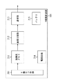
図9は、X線画像を撮影する際のX線発生装置103、X線撮影装置101、及び画像処理装置105の動作の一例を示すタイムチャートである。
X線撮影装置101は、画像処理装置105からの指示を受け、前述した走査線の駆動(走査)を行い、X線の照射を待つ(期間T701)。X線発生装置103からの指示によりX線管球102からX線の照射があると、X線撮影装置101は、X線が照射されたことを検出し、この検出に基づいて、走査線の駆動を順次停止してTFT204をオフする。全走査線においてTFT204がオフすると、電荷蓄積状態となる(期間T702)。この電荷蓄積状態が開始するタイミングでX線撮影装置101は、前記デジタル値(内部電流値情報)を記憶回路606から読み出すと共に、走査を停止した走査線(走査停止行)を特定する走査線番号を制御部202のレジスタから読み出す。そして、X線撮影装置101は、読み出したデジタル値と走査線番号を、画像処理装置105へ送信する(期間T703、図13のステップS1305)。画像処理装置105は、前記デジタル値に対して信号処理を行う(期間T704)。
FIG. 9 is a time chart illustrating an example of operations of the
Upon receiving an instruction from the
図10は、デジタル値及び信号処理を行ったデジタル値の一例を示す図である。縦軸は、値の大きさを示し、横軸は、走査線の位置を示す。図10の横軸の右端が、X線の照射を検出して走査を停止した走査線でのデジタル値を表す。図10の破線で示すグラフ801が、前記デジタル値を示し、実線で示すグラフ802が、信号処理後の前記デジタル値を示す。信号処理は、X線画像の補正をより行いやすくする目的で行われる。具体的に、信号処理は、前記デジタル値のノイズ成分を除去する処理であり、当該処理は、低域通過フィルタ等で実現される。
FIG. 10 is a diagram illustrating an example of a digital value and a digital value subjected to signal processing. The vertical axis indicates the magnitude of the value, and the horizontal axis indicates the position of the scanning line. The right end of the horizontal axis in FIG. 10 represents a digital value at a scanning line where scanning is stopped by detecting X-ray irradiation. A
所定の時間が経過するとX線撮影装置101は、電荷蓄積状態(期間T702)を終了し、走査部203と画像生成部208とを動作させて、TFT204を順次オンして電荷の読み出しを行う。そして、電流−電圧変換回路601による電圧変換と増幅器602による増幅とが行われた後、AD変換器603でデジタル値に変換されて各画素値となる。このようにして、X線画像(放射線画像)を生成する放射線画像生成処理が行われる(期間T705、図13のステップS1306)。本実施形態では、所定の時間が経過することを電荷蓄積状態の終了条件としたが、必ずしもこのようにする必要はない。例えば、X線の照射終了を検出したことを、電荷蓄積状態の終了条件としてもよい。また、所定の時間は固定でもよいが、照射条件等に合わせて可変であることが望ましい。
When a predetermined time elapses, the
X線画像の生成後、X線撮影装置101は、X線画像のデータを画像処理装置105へ送信する。X線撮影装置101は、X線画像を送信する際、所定のルールに則り所定の数の画像に分割し、各分割画像を画像処理装置105に順次送信する。このようにすることによって、画像処理装置105は、全画像分のデータを受け取る前に、その一部に基づくプレビュー画像を生成して表示するプレビュー処理を行うことができる。図11、図12は、画像処理装置105に画素を送信する方法の一例を説明する図である。図11、図12では、画素位置ごとに画像を分割して、1枚のX線画像を4枚の画像として順次送信する例を示す。
After generating the X-ray image, the
図11に示す例では、X線撮影装置101は、X線画像901を2×2画素の単位で区画する(X線画像901の太枠を参照)。そして、X線撮影装置101は、当該2×2画素の中での相対的な画素位置が同じ画素を集結することで、X線画像901を、4枚の分割画像902〜905に分割する。
図12に示す例では、X線撮影装置101は、X線画像1001を4×4画素の単位で区画する(X線画像1001の太枠を参照)。X線撮影装置101は、当該4×4画素の1つの対角線上及び当該対角線に並行な直線上に並ぶ画素を一纏まりの画素として、行及び列がそれぞれ異なる4つの画素を抽出する。X線撮影装置101は、抽出した4つの画素から、当該4×4画素における相対的に画素位置が同じ画素を集結することで、X線画像1001を、4枚の分割画像1002〜1005に分割する。尚、X線画像901、1001を分割する方法は、これら以外の方法でも構わない。また、全画像から所定のルールに則り間引いたプレビュー用画像を最初に画像処理装置105に送信し、その後に改めて全画像を画像処理装置105に送信してもよい。または、これらの方法を組み合わせてもよい。
In the example shown in FIG. 11, the
In the example shown in FIG. 12, the
X線撮影装置101は、最初に分割画像902又は1002を画像処理装置105へ送信する(期間T706、図13のステップS1307)。画像処理装置105は、それを受信しながら、X線撮影装置101から先に送信されて既に必要な信号処理を行ったデジタル値802と、走査を停止した走査線を特定する走査線番号とを用いて、補正処理及び画像処理を必要に応じて順次行う(期間T707)。画像処理は、例えば、オフセット補正、欠陥画素補正、諧調補正、ゲイン補正)等である。
尚、本実施形態では、暗電流に起因する電荷によるオフセット成分の補正は、X線画像の撮影に先立ち取得されている暗電流画像によって行われるものとする。
The
In the present embodiment, it is assumed that the correction of the offset component due to the charge caused by the dark current is performed by the dark current image acquired prior to the imaging of the X-ray image.
以上のようにして画像処理が完了すると、画像処理装置105は、ディスプレイ等の表示装置に一次プレビュー画像を表示する(期間T708)。X線撮影装置101は、次の分割画像903又は1003を画像処理装置105へ送信する(期間T709)。画像処理装置105は、それを受信しながら、既に受信している分割画像902又は1002と合成し、前記と同様に補正処理及び画像処理を行う(期間T710)。画像処理装置105は、補正処理及び画像処理が完了したところで一次プレビュー画像よりも精細度が高い(高精細な)二次プレビュー画像を表示する(期間T711)。その後、X線撮影装置101は、残りの分割画像904又は1004と分割画像905又は1005を画像処理装置105へ送信する(期間T712、T713)。画像処理装置105は、それらを受信しながら、既に受信している分割画像902、903又は1002、1003と合成し、前記と同様に補正処理及び画像処理を行う(期間T714)。画像処理装置105は、補正処理及び画像処理が完了したところで最終的なX線画像を表示する(期間T715、図13のステップS1308)。
When the image processing is completed as described above, the
X線撮影装置101と画像処理装置105との間の通信状態が悪い場合、欠陥補正情報(デジタル値801と走査線番号)やX線画像(分割画像)の送信できない、或いは送信完了ができないことが起こり得る。したがって、所定の時間内(タイムアウト期間内)に、これらの少なくとも何れか一方を受信できない場合、画像処理装置105は、タイムアウトしたことと、環境を変える等して改めて送信処理を行う選択を促すこと等をユーザに報知するための動作を行ってもよい。例えば、表示装置上のGUI(Graphical User Interface)などで表示することができる。またサウンダなどを用いて音で通知するようにしてもよい。尚、この動作は、X線撮影装置101側で行ってもよい。
また、X線画像に比べて、デジタル値801と走査線番号はデータ量が小さい。このため、デジタル値801と走査線番号の通信に使用する通信プロトコルとして、X線画像の通信に使用する通信プロトコルに比べて、送信効率は低いが信頼性の高い通信プロトコルを用いてもよい。例えば、X線撮影装置101と画像処理装置105との間を無線LAN等で接続する場合、X線画像については、高速性を重視しUDP(User Datagram Protcol)を使用できる。一方、デジタル値801と走査線番号については、伝達性が保証されたTCP(Transmission Control Protcol)を使用できる。
When the communication state between the
Compared to the X-ray image, the
以上のように本実施形態では、X線撮影装置101は、X線が照射されたことを検出すると、走査線の駆動を停止し、電荷蓄積状態に移行する。X線撮影装置101は、この電荷蓄積状態が開始するタイミングでバイアス線206に流れる電流のデジタル値と、走査を停止した走査線を特定する走査線番号とを欠陥補正情報として画像処理装置105に送信する。X線撮影装置101は、欠陥補正情報を送信した後に、X線画像(を分割した分割画像)を画像処理装置105に送信する。したがって、X線画像(分割画像)に対する補正処理を開始する前に、X線撮影装置101の内部に流れる電流であって、X線の照射の検出により値が変化する電流のデジタル値を処理することができる。また、このようにすることで画像処理装置105は、X線画像(分割画像)を受信しながら、当該電流の値を用いてX線画像(分割画像)に対する補正処理を順次行うことができる。したがって、X線画像(分割画像)に対して適切な補正処理を行い、且つX線画像(分割画像)の表示を遅らせないことが可能となる。
As described above, in this embodiment, when the
本実施形態では、欠陥補正情報の送信が完了した後に、X線画像(を分割した分割画像)を画像処理装置105の送信を開始する場合を例に挙げて説明した。しかしながら、欠陥補正情報の送信を開始した後にX線画像(を分割した分割画像)を画像処理装置105の送信を開始していれば、前述した効果を得られるので、必ずしもこのようにする必要はない。例えば、本実施形態では、X線画像(放射線画像)を生成した後に、欠陥補正情報の送信を開始する場合を例に挙げて説明した。しかしながら、欠陥補正情報の送信を開始した後に、X線画像(放射線画像)を生成してもよい(図13のステップS1305、S1306は逆であってもよい)。
In the present embodiment, the case where transmission of the X-ray image (divided image obtained by dividing the X-ray image) to the
また、本実施形態では、X線撮影装置101と画像処理装置105とが無線通信を行う場合を例に挙げて説明した。しかしながら、各装置間の通信は汎用ケーブルを用いた有線通信でもよい。また、X線撮影装置101及び画像処理装置105は、無線送受信装置を内蔵したものとしたが、別途無線アクセスポイントを設け、これらとの通信を行う構成としてもよい。
In the present embodiment, the case where the
また、本実施形態では、X線が照射されたことがX線撮影装置101で検出されたことに基づいて電荷蓄積情報(期間T702)に移行する場合を例に挙げて説明した。しかしながら、必ずしもこのようにする必要はない。
図14は、X線画像を撮影する際のX線発生装置103、X線撮影装置101、及び画像処理装置105の動作の変形例を示すタイムチャートである。
図14において、X線発生装置103は、X線撮影装置101に、同期通信信号Reqを送信する。X線撮影装置101は、同期通信信号Reqを受信した後、電荷蓄積状態に移行すると共に(期間T702)、X線発生装置103に同期通信信号Grantを送信する。X線発生装置103は、同期通信信号Grantを受信すると、X線の照射を開始する。尚、このようにした場合でも、図9で示したのと同様に、X線撮影装置101は、電荷蓄積状態が開始するタイミングで欠陥補正情報を生成して画像処理装置105へ送信し、画像処理装置105は、欠陥補正情報に対して信号処理を行うことができる。
Further, in the present embodiment, the case where the
FIG. 14 is a time chart illustrating a modified example of the operations of the
In FIG. 14, the
(第2の実施形態)
次に、第2の実施形態について説明する。本実施形態では、第1の実施形態に対し、X線画像の撮影後、X線の照射が無い状態で再度撮影動作を行って暗電流画像を取得し、X線画像と暗電流画像を用いてオフセット補正を行う。このように、本実施形態は、第1の実施形態に対し、暗電流画像を取得することに関連する処理を追加した点が主として異なる。したがって、本実施形態の説明において、第1の実施形態と同一の部分については、図1〜図10に付した符号と同一の符号を付す等して詳細な説明を省略する。
(Second Embodiment)
Next, a second embodiment will be described. In the present embodiment, in contrast to the first embodiment, after capturing an X-ray image, the imaging operation is performed again without X-ray irradiation to acquire a dark current image, and the X-ray image and the dark current image are used. Offset correction. As described above, this embodiment is mainly different from the first embodiment in that processing related to acquiring a dark current image is added. Therefore, in the description of the present embodiment, the same parts as those in the first embodiment are denoted by the same reference numerals as those in FIGS.
図15は、X線撮影装置101の構成の一例を示す図である。本実施形態のX線撮影装置101は、図2に示したX線撮影装置101に対し、オフセット補正部216が追加されたものである。
図16は、X線画像を撮影する際のX線発生装置103、X線撮影装置101、及び画像処理装置105の動作の一例を示すタイムチャートである。
第1の実施形態で説明した図9と比較し、X線の照射を待ち(期間T701)、X線の照射を検出して電荷を蓄積し(期間T702)、電荷を読み出してX線画像を生成する(期間T705)ことは、本実施形態でも同じである。X線撮影装置101は、X線画像を生成した後、期間T701で行った走査線の駆動(TFT204)を再度行う(期間T1101)。
図17は、期間T701と期間T1101で行う走査の内容の一例を示す図である。
図17(a)において、期間T701での走査がL2行で停止した場合、期間T1101で行う走査は、制御部202のレジスタに記憶された走査線番号に基づいて期間T701での走査を模擬し、同様にL2行で走査を停止する。尚、期間T1101では期間T701と異なり、X線の照射の検出をする必要がないので、検出部205は動作させない。
FIG. 15 is a diagram illustrating an example of the configuration of the
FIG. 16 is a time chart illustrating an example of operations of the
Compared with FIG. 9 described in the first embodiment, the apparatus waits for X-ray irradiation (period T701), detects the X-ray irradiation, accumulates charges (period T702), reads out the charges, and displays an X-ray image. The generation (period T705) is the same in this embodiment. After generating the X-ray image, the
FIG. 17 is a diagram illustrating an example of the contents of scanning performed in the period T701 and the period T1101.
In FIG. 17A, when the scanning in the period T701 is stopped in the L2 row, the scanning performed in the period T1101 simulates the scanning in the period T701 based on the scanning line number stored in the register of the
図17(b)において、期間T1101で、走査線の駆動(走査の模擬)を行っている間に、X線撮影装置101は、デジタル値と走査線番号とを欠陥補正情報として画像処理装置105へ送信する(期間T703)。欠陥補正情報の送信は、第1の実施形態と同様に、X線の照射による電荷蓄積状態(期間T702)中に行っても構わないし、暗電流電荷蓄積状態(期間T1102)中に行っても構わない。画像処理装置105は、欠陥補正情報を受信して、第1の実施形態と同様に処理を行う(期間T704)。暗電流電荷蓄積状態の期間(期間T1102)が、X線の照射による電荷蓄積状態(期間T702)の期間と同じ時間になるようにする。
In FIG. 17B, during the scanning line drive (simulation of scanning) in the period T1101, the
X線撮影装置101は、期間1103において、暗電流電荷を読み出して暗電流画像を生成する暗電流画像生成処理を行う。そして、オフセット補正部216は、先に取得したX線画像から暗電流画像を減算してオフセット補正を行う。以降、オフセット補正したX線画像を画像処理装置105へ送信して処理、表示を行う。これらの手順や処理内容は、第1の実施形態と同様である。
In the period 1103, the
本実施形態では、電荷の読み出し中(期間T705又は期間T1103)にX線撮影装置101が通信を行うことにより生成される画像にノイズが生じる可能性を避けるため、データの送信を電荷の読み出し期間外に行うものとした。しかしながら、例えば、ノイズの影響が十分小さい場合や、より早いプレビュー表示が求められるには、必ずしもこのようにしなくてもよい。
In this embodiment, in order to avoid a possibility that noise is generated in an image generated when the
以上のようにすれば、第1の実施形態で説明した効果に加えて、X線画像に対するオフセット補正を適切に行うことができるという効果が得られる。
本実施形態においても、第1の実施形態で説明した種々の変形例を採用することができる。
In this way, in addition to the effect described in the first embodiment, an effect that the offset correction for the X-ray image can be appropriately performed is obtained.
Also in the present embodiment, various modifications described in the first embodiment can be employed.
尚、前述した実施形態は、何れも本発明を実施するにあたっての具体化の例を示したものに過ぎず、これらによって本発明の技術的範囲が限定的に解釈されてはならないものである。すなわち、本発明はその技術思想、又はその主要な特徴から逸脱することなく、様々な形で実施することができる。 The above-described embodiments are merely examples of implementation in carrying out the present invention, and the technical scope of the present invention should not be construed in a limited manner. That is, the present invention can be implemented in various forms without departing from the technical idea or the main features thereof.
(その他の実施例)
本発明は、以下の処理を実行することによっても実現される。即ち、まず、以上の実施形態の機能を実現するソフトウェア(コンピュータプログラム)を、ネットワーク又は各種記憶媒体を介してシステム或いは装置に供給する。そして、そのシステム或いは装置のコンピュータ(又はCPUやMPU等)が当該コンピュータプログラムを読み出して実行する。
(Other examples)
The present invention is also realized by executing the following processing. That is, first, software (computer program) for realizing the functions of the above embodiments is supplied to a system or apparatus via a network or various storage media. Then, the computer (or CPU, MPU, etc.) of the system or apparatus reads and executes the computer program.
101 X線撮影装置、102 X線管球、103 X線発生装置、104 制御装置、105 画像処理装置 101 X-ray imaging apparatus, 102 X-ray tube, 103 X-ray generation apparatus, 104 control apparatus, 105 image processing apparatus
Claims (8)
放射線撮影装置の内部に流れる電流であって、前記放射線撮影装置に放射線が照射されると値が変化する電流に基づいて、前記放射線撮影装置に放射線が照射されたことを検出する検出手段と、
前記センサを1つまたは複数の行ごとに選択し、選択したセンサに接続された走査線に選択信号を与えて、前記選択したセンサを一定期間オンにする走査を行い、前記検出手段により前記放射線撮影装置に放射線が照射されたことが検出されると、前記走査を停止する走査手段と、
前記検出手段により前記放射線撮影装置に放射線が照射されたことが検出されると、前記センサをオフにして前記センサに電荷を蓄積させ、前記センサをオンにして蓄積した電荷を読み出すことにより放射線画像を生成する放射線画像生成手段と、
前記走査を停止した位置と前記検出手段により前記放射線撮影装置に放射線が照射されたことが検出されたときの前記電流とに基づいて得られる情報であって、前記放射線画像を補正するための補正情報と前記放射線画像とを送信する送信手段と、
前記放射線画像生成手段により前記放射線画像が生成された後に、前記放射線の照射のない状態で前記走査を模擬した走査を行って、暗電流に基づく画像である暗電流画像を生成する暗電流画像生成手段と、
前記暗電流画像生成手段により生成された暗電流画像に基づいて、前記放射線画像生成手段により生成された放射線画像に対してオフセット補正を行うオフセット補正手段とを有し、
前記送信手段は、前記オフセット補正手段によりオフセット補正が行われた放射線画像を送信し、前記補正情報の送信を、前記走査の模擬が行われている期間に行うことを特徴とする放射線撮影装置。 A sensor having a plurality of pixels arranged in a matrix;
Detection means for detecting that the radiation imaging apparatus has been irradiated with a current flowing inside the radiation imaging apparatus, the value of which changes when the radiation imaging apparatus is irradiated with radiation;
Select the sensor for every one or more rows, giving a selection signal to the scanning line connected to the selected the sensor performs scanning of the selected sensor in a predetermined period on the Scanning means for stopping the scanning when it is detected by the detection means that the radiation imaging apparatus is irradiated with radiation; and
If radiation to the radiation imaging device by said detecting means is detected to have been irradiated, the radiation by reading by turning off the sensors to accumulate charges in the sensor and accumulated in the turn on the sensor charge Radiation image generating means for generating an image;
A the current information obtained on the basis of when the radiation to the radiation imaging apparatus is detected to have been illuminated by the position and the previous SL detecting means stops the scanning, for correcting the radiographic image transmitting means for transmitting the correction information and the previous SL radiographic image,
Dark current image generation for generating a dark current image that is an image based on a dark current by performing a scan simulating the scan in a state without irradiation of the radiation after the radiation image is generated by the radiation image generating means Means,
Based on the dark current image generated by the dark current image generation means, and having an offset correction means for performing offset correction on the radiation image generated by the radiation image generation means,
The radiographic apparatus, wherein the transmission unit transmits a radiographic image subjected to offset correction by the offset correction unit, and transmits the correction information during a period during which the scanning is simulated .
前記送信手段は、前記放射線画像を、前記放射線画像の画素の位置に応じて分割した複数の分割画像として順次送信し、
前記プレビュー処理手段は、前記複数の分割画像の一部に基づいてプレビュー画像を生成して前記表示装置に表示することを特徴とする請求項1〜3の何れか1項に記載の放射線撮影装置。 Preview processing means for generating a preview image of the radiation image and displaying it on a display device;
The transmission unit, said radiation image, sequentially transmitted as a plurality of divided images obtained by dividing in accordance with the position of the pixel of the radiographic image,
Said preview processing means, the radiation imaging apparatus according to any one of claim 1 to 3, characterized in that the display on the display device to generate a preview image based on a portion of the plurality of divided images .
放射線撮影装置の内部に流れる電流であって、前記放射線撮影装置に放射線が照射されると値が変化する電流に基づいて、前記放射線撮影装置に放射線が照射されたことを検出する検出手段と、
前記センサを1つまたは複数の行ごとに選択し、選択したセンサに接続された走査線に選択信号を与えて、前記選択したセンサを一定期間オンにする走査を行い、前記検出手段により前記放射線撮影装置に放射線が照射されたことが検出されると、前記走査を停止する走査手段と、
前記検出手段により前記放射線撮影装置に放射線が照射されたことが検出されると、前記センサをオフにして前記センサに電荷を蓄積させ、前記センサをオンにして蓄積した電荷を読み出すことにより放射線画像を生成する放射線画像生成手段と、
前記走査を停止した位置と、前記検出手段により前記放射線撮影装置に放射線が照射されたことが検出されたときの前記電流とに基づいて得られる情報であって、前記放射線画像を補正するための補正情報と前記放射線画像とを送信する送信手段とを有し、
前記送信手段は、前記放射線画像の送信を開始するよりも前に、前記補正情報の送信を開始する放射線撮影装置と、
前記送信手段により送信された前記補正情報を用いて、前記送信手段により送信された前記放射線画像を補正する画像補正手段を有する画像処理装置とを有し、
前記画像処理装置は、前記放射線画像または前記補正情報を所定の時間内に受信できない場合、そのことに関わる情報を報知する報知手段を有することを特徴とする放射線撮影システム。 A sensor having a plurality of pixels arranged in a matrix;
Detection means for detecting that the radiation imaging apparatus has been irradiated with a current flowing inside the radiation imaging apparatus, the value of which changes when the radiation imaging apparatus is irradiated with radiation;
The sensor is selected for each row or rows, a selection signal is given to a scanning line connected to the selected sensor, scanning is performed to turn on the selected sensor for a certain period, and the radiation is detected by the detection unit. Scanning means for stopping the scanning when it is detected that the imaging apparatus is irradiated with radiation; and
When it is detected by the detection means that the radiation imaging apparatus has been irradiated with radiation, the sensor is turned off to accumulate charges in the sensor, and the sensor is turned on and the accumulated charges are read out to obtain a radiation image. A radiation image generating means for generating
Information obtained on the basis of the position where the scanning is stopped and the current when the detection unit detects that the radiation imaging apparatus has been irradiated with radiation, for correcting the radiation image Transmission means for transmitting the correction information and the radiation image,
The transmission means, before starting transmission of the radiation image, a radiation imaging apparatus that starts transmission of the correction information;
An image processing apparatus having an image correction unit that corrects the radiation image transmitted by the transmission unit using the correction information transmitted by the transmission unit;
The radiographic imaging system, wherein the image processing apparatus includes an informing means for informing information related to the radiographic image or the correction information when the radiographic image or the correction information cannot be received within a predetermined time.
行列状に配置された複数の画素を有するセンサを1つまたは複数の行ごとに選択し、選択したセンサに接続された走査線に選択信号を与えて、前記選択したセンサを一定期間オンにする走査を行い、前記検出工程により前記放射線撮影装置に放射線が照射されたことが検出されると、前記走査を停止する走査工程と、
前記検出工程により前記放射線撮影装置に放射線が照射されたことが検出されると、前記センサをオフにして前記センサに電荷を蓄積させ、前記センサをオンにして蓄積した電荷を読み出すことにより放射線画像を生成する放射線画像生成工程と、
前記走査を停止した位置と前記検出工程により前記放射線撮影装置に放射線が照射されたことが検出されたときの前記電流とに基づいて得られる情報であって、前記放射線画像を補正するための補正情報と前記放射線画像とを送信する送信工程と、
前記放射線画像生成工程により前記放射線画像が生成された後に、前記放射線の照射のない状態で前記走査を模擬した走査を行って、暗電流に基づく画像である暗電流画像を生成する暗電流画像生成工程と、
前記暗電流画像生成工程により生成された暗電流画像に基づいて生成された放射線画像に対してオフセット補正を行うオフセット補正工程とを有し、
前記送信工程では、前記オフセット補正が行われた放射線画像を送信し、前記補正情報の送信を、前記走査の模擬が行われている期間に行うことを特徴とする放射線撮影装置の制御方法。 A detection step of detecting that the radiation imaging apparatus is irradiated with radiation based on a current that flows in the radiation imaging apparatus and changes in value when the radiation imaging apparatus is irradiated with radiation;
A sensor having a plurality of pixels arranged in a matrix selected for each one or more rows, giving a selection signal to the scanning line connected to the selected the sensor, the selected sensor Performing a scan for turning on for a certain period of time, and when the detection step detects that the radiation imaging apparatus has been irradiated with radiation, a scanning step of stopping the scan;
If radiation to the radiation imaging apparatus by said detection step is detected to have been irradiated, the radiation by reading by turning off the sensors to accumulate charges in the sensor and accumulated in the turn on the sensor charge A radiation image generating step for generating an image;
A the current information obtained on the basis of when the radiation to the radiation imaging apparatus according to the position and the front Symbol detection step of stopping the scanning is irradiated is detected, to correct the radiation image a transmission step of transmitting the correction information and the previous SL radiographic image,
Dark current image generation for generating a dark current image that is an image based on dark current by performing a scan simulating the scan in a state without irradiation of the radiation after the radiation image is generated by the radiation image generation step Process,
An offset correction step for performing offset correction on the radiation image generated based on the dark current image generated by the dark current image generation step,
In the transmission step, the radiographic image subjected to the offset correction is transmitted, and the correction information is transmitted during a period during which the scanning is simulated .
Priority Applications (2)
| Application Number | Priority Date | Filing Date | Title |
|---|---|---|---|
| JP2013044595A JP6112915B2 (en) | 2013-03-06 | 2013-03-06 | Radiation imaging apparatus and method for controlling radiation imaging apparatus |
| US14/198,784 US9413995B2 (en) | 2013-03-06 | 2014-03-06 | Radiographic apparatus and method for controlling radiographic apparatus |
Applications Claiming Priority (1)
| Application Number | Priority Date | Filing Date | Title |
|---|---|---|---|
| JP2013044595A JP6112915B2 (en) | 2013-03-06 | 2013-03-06 | Radiation imaging apparatus and method for controlling radiation imaging apparatus |
Related Child Applications (1)
| Application Number | Title | Priority Date | Filing Date |
|---|---|---|---|
| JP2017042562A Division JP6305593B2 (en) | 2017-03-07 | 2017-03-07 | Radiation imaging apparatus and method for controlling radiation imaging apparatus |
Publications (3)
| Publication Number | Publication Date |
|---|---|
| JP2014175726A JP2014175726A (en) | 2014-09-22 |
| JP2014175726A5 JP2014175726A5 (en) | 2016-04-21 |
| JP6112915B2 true JP6112915B2 (en) | 2017-04-12 |
Family
ID=51486691
Family Applications (1)
| Application Number | Title | Priority Date | Filing Date |
|---|---|---|---|
| JP2013044595A Active JP6112915B2 (en) | 2013-03-06 | 2013-03-06 | Radiation imaging apparatus and method for controlling radiation imaging apparatus |
Country Status (2)
| Country | Link |
|---|---|
| US (1) | US9413995B2 (en) |
| JP (1) | JP6112915B2 (en) |
Families Citing this family (7)
| Publication number | Priority date | Publication date | Assignee | Title |
|---|---|---|---|---|
| JP6072102B2 (en) * | 2015-01-30 | 2017-02-01 | キヤノン株式会社 | Radiographic system and radiographic method |
| JP2017185153A (en) | 2016-04-08 | 2017-10-12 | キヤノン株式会社 | Radiographic imaging system, radiographic imaging device, radiographic imaging method and program |
| JP6513070B2 (en) * | 2016-12-27 | 2019-05-15 | キヤノン株式会社 | RADIOGRAPHIC IMAGING DEVICE, CONTROL DEVICE, LONG-LENS IMAGING SYSTEM, CONTROL METHOD AND PROGRAM |
| JP7022614B2 (en) * | 2018-02-21 | 2022-02-18 | キヤノン株式会社 | Radiation imaging device, radiation imaging system, control method and program of radiation imaging device |
| CN108596173B (en) * | 2018-04-19 | 2022-02-11 | 长春理工大学 | Single-camera full-view line number real-time recognition device and detection method thereof |
| JP7063199B2 (en) * | 2018-08-31 | 2022-05-09 | コニカミノルタ株式会社 | Radiation imaging system |
| JP2021037370A (en) * | 2020-12-04 | 2021-03-11 | キヤノン株式会社 | Radiographic system, radiographic method and program |
Family Cites Families (8)
| Publication number | Priority date | Publication date | Assignee | Title |
|---|---|---|---|---|
| US8766204B2 (en) * | 2008-06-27 | 2014-07-01 | Konica Minolta Medical & Graphic, Inc. | Portable radiographic image detector and radiographic image generation system |
| JP2011133302A (en) * | 2009-12-24 | 2011-07-07 | Konica Minolta Medical & Graphic Inc | Radiographic imaging device and radiographic imaging system |
| US20130032696A1 (en) * | 2010-04-30 | 2013-02-07 | Konica Minolta Medical & Graphic, Inc. | Radiation image capturing apparatus |
| JP5556367B2 (en) | 2010-05-24 | 2014-07-23 | コニカミノルタ株式会社 | Radiographic imaging apparatus and radiographic imaging system |
| JP5459066B2 (en) * | 2010-05-24 | 2014-04-02 | コニカミノルタ株式会社 | Radiation imaging equipment |
| JP2012152477A (en) | 2011-01-28 | 2012-08-16 | Konica Minolta Medical & Graphic Inc | Radiation imaging system and radiation imaging apparatus |
| JP2013039208A (en) * | 2011-08-15 | 2013-02-28 | Konica Minolta Medical & Graphic Inc | Radiation imaging apparatus and radiation imaging system |
| JP5799750B2 (en) | 2011-10-28 | 2015-10-28 | コニカミノルタ株式会社 | Radiographic imaging system and radiographic imaging device |
-
2013
- 2013-03-06 JP JP2013044595A patent/JP6112915B2/en active Active
-
2014
- 2014-03-06 US US14/198,784 patent/US9413995B2/en active Active
Also Published As
| Publication number | Publication date |
|---|---|
| US9413995B2 (en) | 2016-08-09 |
| US20140252243A1 (en) | 2014-09-11 |
| JP2014175726A (en) | 2014-09-22 |
Similar Documents
| Publication | Publication Date | Title |
|---|---|---|
| JP6112915B2 (en) | Radiation imaging apparatus and method for controlling radiation imaging apparatus | |
| JP5393245B2 (en) | Image processing apparatus, image processing apparatus control method, X-ray image capturing apparatus, and X-ray image capturing apparatus control method | |
| US20130329981A1 (en) | Radiation imaging apparatus, radiation image processing apparatus, and image processing method | |
| JP5894371B2 (en) | Radiation imaging apparatus and control method thereof | |
| EP2773098A3 (en) | Radiation imaging apparatus, method for radiation imaging, and program | |
| JP2014502914A5 (en) | ||
| JP6305593B2 (en) | Radiation imaging apparatus and method for controlling radiation imaging apparatus | |
| WO2016129162A1 (en) | Image processing device, image processing method, program, and image processing system | |
| JP2014175726A5 (en) | ||
| JP2014049979A (en) | Radiographic imaging apparatus, driving method thereof, and radiographic imaging system | |
| KR101689665B1 (en) | Image sensor, image sensing method, and image photographing apparatus including the image sensor | |
| JP5641892B2 (en) | X-ray CT apparatus and control method of X-ray CT apparatus | |
| JP5489577B2 (en) | Radiation imaging system and control method thereof, main control unit and control method thereof, and program | |
| JP2014171532A (en) | Display control apparatus, display control method, and program | |
| JP5262563B2 (en) | Radiation image detection device | |
| US9894306B2 (en) | Radiation imaging system, control apparatus, control method, and storage medium | |
| JP2018038547A (en) | Radiation imaging apparatus, control method thereof, radiation imaging system, and program | |
| JP2004228734A (en) | Dynamic image color correction apparatus | |
| JP2016036374A (en) | Radiographic apparatus and gain image creation method | |
| JP2014171549A (en) | Radiation image capturing apparatus, and control method and program for radiation image capturing apparatus | |
| JP2009159497A (en) | Imaging device and method of controlling same | |
| WO2015059886A1 (en) | Radiographic imaging device and method for controlling same, radiographic image processing device and method, and program and computer-readable storage medium | |
| JP2011117930A (en) | Radiation image forming device and radiation image forming method | |
| JP6853644B2 (en) | Radiation imaging device, radiation imaging system, radiation imaging method and program | |
| JP2015208484A (en) | Image processor, radiographic apparatus, control method for them, radiographic system and program |
Legal Events
| Date | Code | Title | Description |
|---|---|---|---|
| A521 | Request for written amendment filed |
Free format text: JAPANESE INTERMEDIATE CODE: A523 Effective date: 20160303 |
|
| A621 | Written request for application examination |
Free format text: JAPANESE INTERMEDIATE CODE: A621 Effective date: 20160303 |
|
| A977 | Report on retrieval |
Free format text: JAPANESE INTERMEDIATE CODE: A971007 Effective date: 20161114 |
|
| A131 | Notification of reasons for refusal |
Free format text: JAPANESE INTERMEDIATE CODE: A131 Effective date: 20161206 |
|
| A521 | Request for written amendment filed |
Free format text: JAPANESE INTERMEDIATE CODE: A523 Effective date: 20170126 |
|
| TRDD | Decision of grant or rejection written | ||
| A01 | Written decision to grant a patent or to grant a registration (utility model) |
Free format text: JAPANESE INTERMEDIATE CODE: A01 Effective date: 20170214 |
|
| A61 | First payment of annual fees (during grant procedure) |
Free format text: JAPANESE INTERMEDIATE CODE: A61 Effective date: 20170314 |
|
| R151 | Written notification of patent or utility model registration |
Ref document number: 6112915 Country of ref document: JP Free format text: JAPANESE INTERMEDIATE CODE: R151 |