EP4123218B1 - Multi-pixel high beam system, vehicle lamp, and vehicle - Google Patents
Multi-pixel high beam system, vehicle lamp, and vehicle Download PDFInfo
- Publication number
- EP4123218B1 EP4123218B1 EP21809111.4A EP21809111A EP4123218B1 EP 4123218 B1 EP4123218 B1 EP 4123218B1 EP 21809111 A EP21809111 A EP 21809111A EP 4123218 B1 EP4123218 B1 EP 4123218B1
- Authority
- EP
- European Patent Office
- Prior art keywords
- light
- reflector
- individual
- high beam
- reflection
- Prior art date
- Legal status (The legal status is an assumption and is not a legal conclusion. Google has not performed a legal analysis and makes no representation as to the accuracy of the status listed.)
- Active
Links
- 230000007423 decrease Effects 0.000 claims description 8
- 238000005192 partition Methods 0.000 claims description 4
- 125000006850 spacer group Chemical group 0.000 claims description 3
- 238000005286 illumination Methods 0.000 description 8
- 230000015572 biosynthetic process Effects 0.000 description 2
- 230000005465 channeling Effects 0.000 description 2
- 230000003247 decreasing effect Effects 0.000 description 2
- 230000004438 eyesight Effects 0.000 description 2
- 238000009434 installation Methods 0.000 description 2
- 230000003287 optical effect Effects 0.000 description 2
- 206010039203 Road traffic accident Diseases 0.000 description 1
- 230000005540 biological transmission Effects 0.000 description 1
- 230000000694 effects Effects 0.000 description 1
- 238000005516 engineering process Methods 0.000 description 1
- 230000004313 glare Effects 0.000 description 1
- 230000007704 transition Effects 0.000 description 1
Images


Classifications
-
- F—MECHANICAL ENGINEERING; LIGHTING; HEATING; WEAPONS; BLASTING
- F21—LIGHTING
- F21S—NON-PORTABLE LIGHTING DEVICES; SYSTEMS THEREOF; VEHICLE LIGHTING DEVICES SPECIALLY ADAPTED FOR VEHICLE EXTERIORS
- F21S41/00—Illuminating devices specially adapted for vehicle exteriors, e.g. headlamps
- F21S41/30—Illuminating devices specially adapted for vehicle exteriors, e.g. headlamps characterised by reflectors
- F21S41/32—Optical layout thereof
- F21S41/36—Combinations of two or more separate reflectors
- F21S41/365—Combinations of two or more separate reflectors successively reflecting the light
-
- F—MECHANICAL ENGINEERING; LIGHTING; HEATING; WEAPONS; BLASTING
- F21—LIGHTING
- F21S—NON-PORTABLE LIGHTING DEVICES; SYSTEMS THEREOF; VEHICLE LIGHTING DEVICES SPECIALLY ADAPTED FOR VEHICLE EXTERIORS
- F21S41/00—Illuminating devices specially adapted for vehicle exteriors, e.g. headlamps
- F21S41/10—Illuminating devices specially adapted for vehicle exteriors, e.g. headlamps characterised by the light source
- F21S41/14—Illuminating devices specially adapted for vehicle exteriors, e.g. headlamps characterised by the light source characterised by the type of light source
- F21S41/141—Light emitting diodes [LED]
- F21S41/147—Light emitting diodes [LED] the main emission direction of the LED being angled to the optical axis of the illuminating device
- F21S41/148—Light emitting diodes [LED] the main emission direction of the LED being angled to the optical axis of the illuminating device the main emission direction of the LED being perpendicular to the optical axis
-
- F—MECHANICAL ENGINEERING; LIGHTING; HEATING; WEAPONS; BLASTING
- F21—LIGHTING
- F21S—NON-PORTABLE LIGHTING DEVICES; SYSTEMS THEREOF; VEHICLE LIGHTING DEVICES SPECIALLY ADAPTED FOR VEHICLE EXTERIORS
- F21S41/00—Illuminating devices specially adapted for vehicle exteriors, e.g. headlamps
- F21S41/10—Illuminating devices specially adapted for vehicle exteriors, e.g. headlamps characterised by the light source
- F21S41/14—Illuminating devices specially adapted for vehicle exteriors, e.g. headlamps characterised by the light source characterised by the type of light source
- F21S41/141—Light emitting diodes [LED]
- F21S41/151—Light emitting diodes [LED] arranged in one or more lines
-
- F—MECHANICAL ENGINEERING; LIGHTING; HEATING; WEAPONS; BLASTING
- F21—LIGHTING
- F21S—NON-PORTABLE LIGHTING DEVICES; SYSTEMS THEREOF; VEHICLE LIGHTING DEVICES SPECIALLY ADAPTED FOR VEHICLE EXTERIORS
- F21S41/00—Illuminating devices specially adapted for vehicle exteriors, e.g. headlamps
- F21S41/20—Illuminating devices specially adapted for vehicle exteriors, e.g. headlamps characterised by refractors, transparent cover plates, light guides or filters
- F21S41/24—Light guides
-
- F—MECHANICAL ENGINEERING; LIGHTING; HEATING; WEAPONS; BLASTING
- F21—LIGHTING
- F21S—NON-PORTABLE LIGHTING DEVICES; SYSTEMS THEREOF; VEHICLE LIGHTING DEVICES SPECIALLY ADAPTED FOR VEHICLE EXTERIORS
- F21S41/00—Illuminating devices specially adapted for vehicle exteriors, e.g. headlamps
- F21S41/30—Illuminating devices specially adapted for vehicle exteriors, e.g. headlamps characterised by reflectors
- F21S41/32—Optical layout thereof
- F21S41/321—Optical layout thereof the reflector being a surface of revolution or a planar surface, e.g. truncated
-
- F—MECHANICAL ENGINEERING; LIGHTING; HEATING; WEAPONS; BLASTING
- F21—LIGHTING
- F21S—NON-PORTABLE LIGHTING DEVICES; SYSTEMS THEREOF; VEHICLE LIGHTING DEVICES SPECIALLY ADAPTED FOR VEHICLE EXTERIORS
- F21S41/00—Illuminating devices specially adapted for vehicle exteriors, e.g. headlamps
- F21S41/30—Illuminating devices specially adapted for vehicle exteriors, e.g. headlamps characterised by reflectors
- F21S41/32—Optical layout thereof
- F21S41/322—Optical layout thereof the reflector using total internal reflection
-
- F—MECHANICAL ENGINEERING; LIGHTING; HEATING; WEAPONS; BLASTING
- F21—LIGHTING
- F21S—NON-PORTABLE LIGHTING DEVICES; SYSTEMS THEREOF; VEHICLE LIGHTING DEVICES SPECIALLY ADAPTED FOR VEHICLE EXTERIORS
- F21S41/00—Illuminating devices specially adapted for vehicle exteriors, e.g. headlamps
- F21S41/30—Illuminating devices specially adapted for vehicle exteriors, e.g. headlamps characterised by reflectors
- F21S41/32—Optical layout thereof
- F21S41/36—Combinations of two or more separate reflectors
-
- F—MECHANICAL ENGINEERING; LIGHTING; HEATING; WEAPONS; BLASTING
- F21—LIGHTING
- F21S—NON-PORTABLE LIGHTING DEVICES; SYSTEMS THEREOF; VEHICLE LIGHTING DEVICES SPECIALLY ADAPTED FOR VEHICLE EXTERIORS
- F21S41/00—Illuminating devices specially adapted for vehicle exteriors, e.g. headlamps
- F21S41/30—Illuminating devices specially adapted for vehicle exteriors, e.g. headlamps characterised by reflectors
- F21S41/39—Attachment thereof
-
- F—MECHANICAL ENGINEERING; LIGHTING; HEATING; WEAPONS; BLASTING
- F21—LIGHTING
- F21S—NON-PORTABLE LIGHTING DEVICES; SYSTEMS THEREOF; VEHICLE LIGHTING DEVICES SPECIALLY ADAPTED FOR VEHICLE EXTERIORS
- F21S41/00—Illuminating devices specially adapted for vehicle exteriors, e.g. headlamps
- F21S41/40—Illuminating devices specially adapted for vehicle exteriors, e.g. headlamps characterised by screens, non-reflecting members, light-shielding members or fixed shades
- F21S41/43—Illuminating devices specially adapted for vehicle exteriors, e.g. headlamps characterised by screens, non-reflecting members, light-shielding members or fixed shades characterised by the shape thereof
-
- F—MECHANICAL ENGINEERING; LIGHTING; HEATING; WEAPONS; BLASTING
- F21—LIGHTING
- F21S—NON-PORTABLE LIGHTING DEVICES; SYSTEMS THEREOF; VEHICLE LIGHTING DEVICES SPECIALLY ADAPTED FOR VEHICLE EXTERIORS
- F21S41/00—Illuminating devices specially adapted for vehicle exteriors, e.g. headlamps
- F21S41/60—Illuminating devices specially adapted for vehicle exteriors, e.g. headlamps characterised by a variable light distribution
- F21S41/65—Illuminating devices specially adapted for vehicle exteriors, e.g. headlamps characterised by a variable light distribution by acting on light sources
- F21S41/663—Illuminating devices specially adapted for vehicle exteriors, e.g. headlamps characterised by a variable light distribution by acting on light sources by switching light sources
-
- F—MECHANICAL ENGINEERING; LIGHTING; HEATING; WEAPONS; BLASTING
- F21—LIGHTING
- F21S—NON-PORTABLE LIGHTING DEVICES; SYSTEMS THEREOF; VEHICLE LIGHTING DEVICES SPECIALLY ADAPTED FOR VEHICLE EXTERIORS
- F21S45/00—Arrangements within vehicle lighting devices specially adapted for vehicle exteriors, for purposes other than emission or distribution of light
- F21S45/40—Cooling of lighting devices
- F21S45/47—Passive cooling, e.g. using fins, thermal conductive elements or openings
-
- F—MECHANICAL ENGINEERING; LIGHTING; HEATING; WEAPONS; BLASTING
- F21—LIGHTING
- F21S—NON-PORTABLE LIGHTING DEVICES; SYSTEMS THEREOF; VEHICLE LIGHTING DEVICES SPECIALLY ADAPTED FOR VEHICLE EXTERIORS
- F21S41/00—Illuminating devices specially adapted for vehicle exteriors, e.g. headlamps
- F21S41/50—Illuminating devices specially adapted for vehicle exteriors, e.g. headlamps characterised by aesthetic components not otherwise provided for, e.g. decorative trim, partition walls or covers
-
- F—MECHANICAL ENGINEERING; LIGHTING; HEATING; WEAPONS; BLASTING
- F21—LIGHTING
- F21W—INDEXING SCHEME ASSOCIATED WITH SUBCLASSES F21K, F21L, F21S and F21V, RELATING TO USES OR APPLICATIONS OF LIGHTING DEVICES OR SYSTEMS
- F21W2102/00—Exterior vehicle lighting devices for illuminating purposes
- F21W2102/10—Arrangement or contour of the emitted light
- F21W2102/13—Arrangement or contour of the emitted light for high-beam region or low-beam region
- F21W2102/135—Arrangement or contour of the emitted light for high-beam region or low-beam region the light having cut-off lines, i.e. clear borderlines between emitted regions and dark regions
- F21W2102/14—Arrangement or contour of the emitted light for high-beam region or low-beam region the light having cut-off lines, i.e. clear borderlines between emitted regions and dark regions having vertical cut-off lines; specially adapted for adaptive high beams, i.e. wherein the beam is broader but avoids glaring other road users
- F21W2102/145—Arrangement or contour of the emitted light for high-beam region or low-beam region the light having cut-off lines, i.e. clear borderlines between emitted regions and dark regions having vertical cut-off lines; specially adapted for adaptive high beams, i.e. wherein the beam is broader but avoids glaring other road users wherein the light is emitted between two parallel vertical cutoff lines, e.g. selectively emitted rectangular-shaped high beam
-
- F—MECHANICAL ENGINEERING; LIGHTING; HEATING; WEAPONS; BLASTING
- F21—LIGHTING
- F21W—INDEXING SCHEME ASSOCIATED WITH SUBCLASSES F21K, F21L, F21S and F21V, RELATING TO USES OR APPLICATIONS OF LIGHTING DEVICES OR SYSTEMS
- F21W2102/00—Exterior vehicle lighting devices for illuminating purposes
- F21W2102/20—Illuminance distribution within the emitted light
Definitions
- the present invention relates to a vehicle lamp, in particular to a multi-pixel high beam system.
- the present invention also relates to a vehicle lamp and a vehicle.
- the intelligent system of vehicles is becoming more and more popular.
- the multi-pixel intelligent high beam function is the most widely used. It can ensure the driver's driving vision to the maximum extent and improve the safety and comfort of vehicle driving under the premise of preventing drivers of other vehicles from being dazzled.
- reflective form and projected form Compared with the reflective system, projection elements such as lenses needs to be added for the projection system, resulting in that the cost is much higher than that of the reflective system; while the reflective system is composed of reflecting mirrors, which has certain advantages in cost.
- the width of a single pixel of multi-pixel intelligent high beam can be independently set according to the actual situation on the vehicle driving road (i.e.
- a dark area with high resolution needs to be formed, and the width of a single pixel should be narrow, so that the width of the formed dark area can be controlled more accurately, which is consistent with the width of the area where the vehicles or pedestrians are located, which can prevent the other party from being dazzled and also ensure the driver's field of vision in this vehicle; while for the area on two sides of the front of the lane wherein the vehicles or pedestrians are fewer, there is no need to form a dark area with high resolution, and the width of a single pixel can be increased, so that for the widths of the multiple pixels of the high beam light shape, a gradual trend of decrease (i.e. from wide to narrow) from the outside to the inside is formed.
- One structure of the current reflective multi-pixel high beam system is composed of multi-chip light-emitting light sources (in which the chips are arranged laterally) and a reflecting mirror.
- the light emitted from the light-emitting light source is reflected by the reflecting mirror, and then form a high beam light shape with a certain width corresponding to the size of the light-emitting chip, wherein the number of pixels is determined by the number of chips, and the width of a single pixel is jointly determined by a single light-emitting chip and the reflecting mirror, the width range of a single pixel is very small, resulting in a small difference between the widths of different pixels. For situations where different pixels with greatly different widths are required, such a system cannot meet the above-mentioned requirements.
- the Chinese invention patent with application date of September 27, 2017 and publication number CN107420825A discloses another structure of a reflective multi-pixel high beam system, which consists of a reflecting mirror and multiple LED light sources, wherein since the multiple LED light sources share one reflecting mirror, the focal point of the reflecting mirror must be set on the LED light source in the middle position.
- other LED light sources need to be as close to the focal point of the reflecting mirror as possible, and all LED light sources correspond to the one reflecting mirror, so that the widths of individual pixels formed corresponding to the individual LED light sources are basically the same. It is not possible to change the width of each pixel therein individually, so it is still impossible to meet the multi-pixel combination requirements with specific widths.
- EP 2789900A2 discloses a light module of a motor vehicle lighting device, which comprises several separately controllable light sources combined to form an array for emitting light, several primary optics elements combined to form a primary optics array in the form of converging lenses, each with a light entry surface and a light exit surface.
- the technical problem to be solved by the present invention is to provide a multi-pixel high beam system, which can form a multi-pixel high-beam light shape with a specific width and meet the multi-pixel intelligent illumination requirements.
- the technical problem to be solved by the present invention is to provide a vehicle lamp, wherein by providing the multi-pixel high-beam system, the vehicle lamp can form a multi-pixel high beam light shape with a specific width to meet the multi-pixel intelligent illumination requirements of the vehicle lamp.
- the technical problem to be solved by the present invention is to provide a vehicle, wherein by providing the vehicle lamp, the vehicle can form a multi-pixel high beam light shape with a specific width to meet the multi-pixel intelligent illumination requirements of the vehicle.
- the present invention provides a multi-pixel high beam system according to claim 1.
- the widths of the plurality of pixels gradually decrease from an outer region of the light shape to a central region of the light shape.
- the light collimation element is a multi-cavity reflector
- the multi-cavity reflector comprises a plurality of reflection cavities arranged in parallel and having set widths, and the reflection cavities are formed as the light collimation units.
- the reflection surfaces of the individual reflection cavities are all paraboloids, and the individual light-emitting light sources are respectively provided at focal points of the individual reflection cavities in a one-to-one correspondence, and a partition rib is provided between the each adjacent reflection cavities.
- a light shielding part configured to shield a part of direct lights of the light-emitting light sources is provided in front of the light-emitting light sources.
- the light collimation element is a light collimator
- the light collimator comprises a plurality of alignment units arranged in parallel, light incident ends of the individual alignment units are separated from each other, and the light incident ends of the individual alignment units are in one-to-one correspondence with the individual light-emitting light sources, light exit ends of the individual alignment units are connected with each other to constitute a light exit surface, wherein end surfaces of the light exit ends of the individual alignment units respectively have set widths to form the light collimation units.
- two reflective elements are provided, which are respectively a first reflector and a second reflector, wherein the first reflector is provided directly in front of the light collimation element, and the second reflector is located above or below the light collimation element, and lights emitted by the individual light-emitting light sources are converged by the light collimation element, and then reflected by the first reflector and the second reflector in sequence to form the light shape having the plurality of pixels.
- a reflection surface of the first reflector is a plane, and the first reflector is obliquely provided directly in front of the light collimation element.
- the second reflector comprises two reflection surfaces with a segment difference, and a spacer plate is provided between the two reflection surfaces, and the two reflection surfaces correspond to one focal point, respectively.
- the first reflector and the light collimation element are integrally formed.
- each of the light-emitting light sources is a single-chip light-emitting light source and can be lit independently.
- each of the light-emitting light sources is provided on a circuit board, and the light collimation element, the reflective elements and the circuit board are all fixed on a heat sink.
- the present invention can form a high beam light shape having a plurality of pixels with specific widths, and by setting the widths of individual light collimation units of the light collimation element, light spots with widths corresponding to the widths of individual light collimation units can be formed, the light spots are arranged in sequence to form a plurality of pixels, so that the width of each of pixels can be adjusted, so as to set the width of a single pixel separately according to the actual condition on a vehicle driving road, thereby meeting the multi-pixel intelligent illumination requirements.
- Transmission elements such as lenses do not need to be added in the present invention, which enables few system parts, simple assembly, compact structure and low cost.
- the present invention also provides a vehicle lamp, which comprises the above-mentioned multi-pixel high beam system.
- the present invention also provides a vehicle, which includes the above-mentioned vehicle lamp.
- orientation or positional relations indicated by terms such as “upper”, “lower”, “left”, “right”, and “front” are merely for facilitating the description of the present disclosure and simplifying the description, rather than indicating or implying that related devices or elements have to be in the specific orientation, or configured or operated in a specific orientation, therefore, they should not be construed as limitations on the present disclosure.
- “left” refers to the direction of the left hand when looking straight ahead of the car in the car
- “right” refers to the direction of the right hand when looking straight ahead of the car in the car
- “upper”, “lower”, “front”, and “rear” are all based on the orientation shown in FIG. 2 .
- the present invention provides a multi-pixel high beam system, which comprises a plurality of light-emitting light sources 1, and a light collimation element and at least one reflective element which cooperate with the light-emitting light sources 1, wherein the light collimation element is provided with a plurality of light collimation units arranged in parallel and having set widths, the individual light-emitting light sources 1 are respectively in one-to-one correspondence with the individual light collimation units, so that lights emitted by the individual light-emitting light sources 1 are converged by the light collimation element, and then reflected by the reflective element to form a plurality of light spots, the plurality of light spots are arranged in sequence to form a light shape having a plurality of pixels, and widths of the individual light spots correspond to the set widths of the individual light collimation units.
- each of grids of the high beam light shape a represents a pixel
- the high beam light shape a is formed by arranging a plurality of light spots in sequence in the left-right direction. If the individual light spots are just converged (connected) to each other, the width of the pixel is the same as the width of the corresponding light spot. However, in this case, there will be a distinct light-dark dividing line between individual pixels, which makes uniformity of the high beam light shape poor. Therefore, in order to make the convergence transition between the individual pixels even, there will be a partial overlap between the individual light spots.
- the width of the light spot should be larger than the width of the corresponding pixel, and the width of the light spot corresponds to the width of the corresponding light collimation unit. Therefore, in order to realize the light shape with high resolution near the area directly in front of the vehicle and low resolution in the area ot two sides in front of the vehicle as shown in FIG. 13 and FIG. 14 , light spots with different widths can be obtained by setting the widths of individual light collimation units, so as to form a multi-pixel high beam light shape having a plurality of pixels with specific widths.
- the area where the light shape near the area directly in front of the vehicle is projected on the light distribution screen is the light shape central area in the schematic views of light shapes shown in FIG. 13 and FIG.
- the area where the intersection of the horizontal 0-degree line and the vertical 0-degree line is located), and the area where the light shapes at the two sides in front of the vehicle are projected on the light distribution screen is the outer region of the light shapes in the schematic views of light shapes shown in FIG. 13 and FIG. 14 .
- the light collimation element of the present invention is provided with a plurality of light collimation units arranged in parallel and having set widths, so that the lights emitted by the individual light-emitting light sources 1 can be collected and converged by the light collimation element, and reflected by the reflective element to form a high beam light shape having a plurality of pixels with specific widths, and by setting the widths of individual light collimation units of the light collimation element, light spots with widths corresponding to the widths of individual light collimation units can be formed, thereby forming a plurality of pixels with specific widths, so that the width of each of pixels can be adjusted, so as to set the width of a single pixel separately according to the actual condition on a vehicle driving road, thereby meeting the multi-pixel intelligent illumination requirements.
- the light collimation element is a multi-cavity reflector 2
- the multi-cavity reflector 2 includes a plurality of reflection cavities 21 arranged in parallel and having set widths, wherein the reflection cavities 21 are the light collimation units on the above-mentioned light collimation element.
- two reflective elements are provided, which are a first reflector 4 and a second reflector 3 respectively.
- the first reflector 4 is provided directly in front of the multi-cavity reflector 2, the second reflector 3 is located below the multi-cavity reflector 2, and the lights emitted by the individual light-emitting light sources 1 are collected and converged by the multi-cavity reflector 2, and then reflected by the first reflector 4 and the second reflector 3 in sequence to form a high beam light shape having a plurality of pixels.
- the incident and exit directions of the lights can be better adjusted through multi-level reflection, so as to better form the expected high beam light shape, and make the structure of the present invention more compact.
- the reflection surfaces of the individual reflection cavities 21 are all paraboloids, and the individual light-emitting light sources 1 are respectively provided on focal points of the individual reflection cavities 21 in a one-to-one correspondence.
- the reflection surfaces of the individual reflection cavities 21 may also be cambered reflection surfaces such as arc-shaped surfaces, and ellipsoid surfaces, as long as they can collect and converge the lights emitted by the light-emitting light sources 1 and reflect them to the first reflector 4.
- a partition rib 22 is provided between each adjacent reflection cavities 21 to separate them from each other, in order to prevent the formation of stray light due to the phenomenon of light channeling between adjacent reflection cavities 21 which affects the formation of the expected light shape,.
- the multi-cavity reflector 2 includes eight reflection cavities 21, and the widths of individual reflection cavities 21 can be adjusted according to the actual light distribution and the widths of the light spots that need to be obtained.
- the widths of individual reflection cavities 21 from right to left are set to correspond to the widths of individual pixels in FIG.13 from left to right, wherein, in FIG.
- a refers to the high beam light shape with eight pixels
- b refers to the low beam light shape
- c refers to the low beam light-dark cut-off line.
- the widths of the eight pixels in FIG. 13 gradually decrease from the left (outer region of the light shape) to the right (the central region of the light shape), and in theory, the widths of individual reflection cavities 21 are set to have a trend of decreasing gradually from right to left. However, for the uniform convergence (connection) between the pixels, the individual light spots are made to be partially superimposed, the widths of individual reflection cavities 21 as shown in FIG.
- the widths of individual reflection cavities 21 from right to left are set to correspond to the widths of individual pixels in FIG.14 from left to right, wherein in FIG. 14 , a refers to the high beam light shape with eight pixels, b refers to the low beam light shape, and c refers to the low beam light-dark cut-off line.
- the widths of the eight pixels in FIG. 14 a refers to the high beam light shape with eight pixels, b refers to the low beam light shape, and c refers to the low beam light-dark cut-off line.
- the widths of individual reflection cavities 21 are set to have a trend of increasing gradually from right to left.
- the widths of individual reflection cavities 21 can be set according to the widths of the light spots that need to be obtained, and do not necessarily have a trend of gradual change in size, as long as a light shape in which the pixel widths gradually decrease from the outer region of the light shape to the central region of the light shape can be obtained, after individual light spots are finally arranged.
- a high beam light shape with wide pixel width (low resolution) in the outer region of the light shape and narrow pixel width (high resolution) in the central region of the light shape can be formed.
- the width setting of the multiple reflection cavities 21 of the multi-cavity reflector 2 can be implemented in different ways, and in all case, a high beam light shape with wide pixel width (low resolution) in the outer region of the light shape and narrow pixel width (high resolution) in the central region of the light shape can be formed after the exiting light shapes of the left and right vehicle lamps are superimposed. Referring to FIG. 15 to FIG. 17 , FIG.
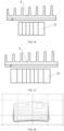
- FIG. 15 is a structural schematic view of a front view when the multi-cavity reflector 2 is applied to the left vehicle lamp (that is, the view structure presented when seeing from the front of the vehicle to the inside of the vehicle in the case that the multi-cavity reflector 2 is installed in the left vehicle lamp), the widths of the first reflection cavity 21, the second reflection cavity 21, the third reflection cavity 21 and the fourth reflection cavity 21 counted from the left side thereof are not much different, and the width of the fifth reflection cavity 21 is larger than that of the fourth reflection cavity 21, and the width of the sixth reflection cavity 21 is greater than the width of the fifth reflection cavity 21.
- the overall exiting light shape formed on the light distribution screen is specifically shown in FIG. 18 , and FIG. 19 to FIG.
- the width of the dark area between the formed light spot corresponding to the third reflection cavity 21 and the formed light spot corresponding to the fifth reflection cavity 21 is the pixel width corresponding to the fourth reflection cavity 21, which is larger than the pixel width corresponding to the second reflection cavity 21 located on the right side thereof (that is, the width of the dark area between the formed light spot corresponding to the first reflection cavity 21 and the formed light spot corresponding to the third reflection cavity 21).
- the pixel width corresponding to the fourth reflection cavity 21 which is larger than the pixel width corresponding to the second reflection cavity 21 located on the right side thereof (that is, the width of the dark area between the formed light spot corresponding to the first reflection cavity 21 and the formed light spot corresponding to the third reflection cavity 21).
- the pixel width corresponding to the fifth reflection cavity 21 is larger than the pixel width corresponding to the third reflection cavity 21 located on the right side thereof.
- the pixel width corresponding to the fifth reflection cavity 21 is larger than the pixel width corresponding to the fourth reflection cavity 21 located on the right side thereof, and the pixel width corresponding to the fourth reflection cavity 21 is larger than the pixel width corresponding to the third reflection cavity 21 located on the right side thereof.
- the pixel width corresponding to the third reflection cavity 21 is similar to the pixel width corresponding to the second reflection cavity 21 located on right side thereof, which conforms to the characteristic that the pixel width of the light shape exited from the left vehicle lamp gradually decreases from the outer region of the light shape to the central region of the light shape.
- FIG. 16 is a structural schematic view of a front view when the multi-cavity reflector 2 applied to the right vehicle lamp, the variation rule of the width of the reflection cavity 21 thereof is opposite to the variation rule of the width of the reflection cavity 21 shown in FIG. 15 .
- FIG. 17 is another structural schematic view of a front view when the multi-cavity reflectors 2 are applied to the left vehicle lamp and the right vehicle lamp, wherein the structures of the multi-cavity reflectors 2 applied to the left vehicle lamp and the right vehicle lamp are the same, the widths of the reflective cavities 21 thereof gradually decrease from the two sides to the middle.
- each of the light-emitting light sources 1 is a single-chip light-emitting light source and can be lit independently, such that in practical application, by controlling the on and off of individual light-emitting light sources, the brightness and darkness of the corresponding pixel can be realized, so that the self-adaptive high beam illumination can be flexibly realized.
- a reflection surface of the first reflector 4 is a plane
- the first reflector 4 is obliquely provided directly in front of the multi-cavity reflector 2 from top to bottom in a direction away from the lighting-emitting light source 1, so that the lights converged and reflected by the multi-cavity reflector 2 is made to be incident on the reflection surface of the second reflector 3 after being reflected by the first reflector 4.
- the reflection surface of the first reflector 4 can also be other curved surfaces that can reflect light.
- the second reflector 3 includes two reflection surfaces with a segment difference, that is, the second reflector 3 is formed by splicing two reflection surfaces with the segment difference, and the two reflection surfaces are preferably paraboloidic reflection surface.
- the two reflection surfaces correspond to one focal point respectively, which enables better light shape effect compared with the case in which one reflection surface with one focal point is used, and simultaneously, if the reflection surface of the second reflector 3 is a whole reflection surface, the width of the reflection surface in the left-right direction needs to be large to ensure that the required light shape can be obtained, while if the reflection surface is divided into two reflection surfaces, the two reflection surfaces can be subjected to respective design and adjustment, so that the reflection surface of the second reflector 3 does not need to be large to form an expected light shape.
- a spacer plate 31 is provided between the two reflection surfaces, in order to prevent light channeling from affecting the light efficiency.
- a light shielding part 8 configured to shield a part of direct lights incident on the multi-cavity reflector 2 is provided in front of the light-emitting light sources 1, and the light shielding part 8 is located above the multi-cavity reflector 2. If this part of the direct lights are reflected by the multi-cavity reflector 2 and reflective element in sequence to the front of the vehicle, this part of the direct lights will cause dazzling pedestrians or oncoming car drivers, which is prone to causing traffic accidents; the light shielding part 8 can also prevent the scattered or diffused lights from the light-emitting light sources 1 from being projected towards a specific area of the multi-cavity reflector 2, so as to avoid the appearance of unwanted light and glare other than the light shape pattern expected to be obtained. As shown in FIG. 7 , the light shielding part 8 is in a plate-like structure, and the light shielding part 8 is preferably integrally formed with the heat sink 5, so that no additional installation structure is required, and the structure is more compact.
- the light collimation element is a multi-cavity reflector 2
- the multi-cavity reflector 2 comprises a plurality of reflection cavities 21 arranged in parallel and having set widths.
- Two reflective elements are provided, which are respectively a first reflector 4 and a second reflector 3, wherein the first reflector 4 is provided directly in front of the multi-cavity reflector 2, and the second reflector 3 is located above the multi-cavity reflector 2, and lights emitted by the individual light-emitting light sources 1 are collected and converged by the multi-cavity reflector 2, and then reflected by the first reflector 4 and the second reflector 3 in sequence to form a high beam light shape having a plurality of pixels.
- the first reflector 4 is obliquely provided directly in front of the multi-cavity reflector 2 from top to bottom in a direction close to the light-emitting light source 1, in order that the lights converged and reflected by the multi-cavity reflector 2 can be incident on the reflection surface of the second reflector 3 after being reflected through the first reflector 4.
- the light collimation element is a light collimator 9, and the light collimator 9 comprises a plurality of alignment units 91 arranged in parallel.
- Light incident ends of the individual alignment units 91 are separated from each other, and the light incident ends of the individual alignment units 91 are in one-to-one correspondence with the individual light-emitting light sources 1, light exit ends of the individual alignment units 91 are connected with each other to constitute a light exit surface, wherein end surfaces of the light exit ends of the individual alignment units 91 respectively have set widths to form the above-mentioned light collimation unit.
- Two reflective elements are provided, which are respectively a first reflector 4 and a second reflector 3, wherein the first reflector 4 is provided directly in front of the light collimator 9, and the second reflector 3 is located below the light collimator 9.
- the second reflector 3 may be also located above the light collimator 9, and lights emitted by the individual light-emitting light sources 1 are converged by the light collimator 9, and then reflected by the first reflector 4 and the second reflector 3 in sequence to form a high beam light shape having a plurality of pixels.
- one reflective element is provided, which is a second reflector 3, and the second reflector 3 is provided below the multi-cavity reflector 2.
- the selection of the number of reflective elements is related to the light shape to be formed.
- the reflective elements can properly diffuse the light, and the number of the reflective elements and the relative positions of reflective elements need to be selected according to light distribution requirements.
- each of the light-emitting light sources 1 is provided on a circuit board 6, and the light collimation element, the reflective elements and the circuit board 6 are all fixed on a heat sink 5.
- the light collimation element is a multi-cavity reflector 2, and two reflective elements are provided, which are a first reflector 4 and a second reflector 3 respectively.
- the first reflector 4 is provided directly in front of the multi-cavity reflector 2, and the second reflector 3 is located below the multi-cavity reflector 2, wherein the multi-cavity reflector 2 and the first reflector 4 are preferably integrally formed, which can make the structure more compact and the installation more convenient.
- the two ends of the integrally molded part are respectively provided with a positioning hole 7 and a fixed hole
- the two ends of the second reflector 3 are respectively provided with a positioning hole 7 and a fixed hole
- the circuit board 6 on which the light-emitting light sources 1 are installed is also provided with positioning holes 7 and fixed holes
- corresponding positions on the heat sink 5 are provided with bolt holes matched (cooperating) with the individual fixed holes and positioning pins 51 matched (cooperating) with the individual positioning holes 7.
- the circuit board 6 on which the light-emitting light sources 1 are installed is first positioned and placed on the heat sink 5, even if the positioning pins 51 on the heat sink 5 pass through the positioning holes 7 of the circuit board 6, and then the integrally molded part of the multi-cavity reflector 2 and the first reflector 4, and the second reflector 3 are respectively positioned and installed on the heat sink 5 through cooperating of the positioning holes 7 and the positioning pins 51, and finally tightened and fixed by bolts, so that the circuit board 6 on which the light-emitting light sources 1 are installed, the integrally molded part of the multi-cavity reflector 2 and the first reflector 4, and the second reflector 3 are respectively positioned and fixedly installed on the heat sink 5.
- the present invention also provides a vehicle lamp, which includes the above-mentioned multi-pixel high beam system.
- the vehicle lamp can form a high beam light shape having a plurality of pixels with specific widths, and the width of each pixel can be independently set according to the actual condition on a vehicle driving road, thereby meeting the multi-pixel intelligent illumination requirements of the vehicle lamp.
- the present invention also provides a vehicle, which includes the above-mentioned vehicle lamp.
- the vehicle By arranging the vehicle lamp, the vehicle can form a high beam light shape having a plurality of pixels with specific widths, and the width of each pixel can be independently set according to the actual condition on a vehicle driving road, thereby meeting the multi-pixel intelligent illumination requirements of the vehicle.
Description
- The present invention claims priority of
Chinese patent application with the filing number 202010444135.2 - The present invention relates to a vehicle lamp, in particular to a multi-pixel high beam system. In addition, the present invention also relates to a vehicle lamp and a vehicle.
- The intelligent system of vehicles is becoming more and more popular. At present, the multi-pixel intelligent high beam function is the most widely used. It can ensure the driver's driving vision to the maximum extent and improve the safety and comfort of vehicle driving under the premise of preventing drivers of other vehicles from being dazzled. There are currently two main forms to achieve multi-pixel high beam that can be turned off: reflective form and projected form. Compared with the reflective system, projection elements such as lenses needs to be added for the projection system, resulting in that the cost is much higher than that of the reflective system; while the reflective system is composed of reflecting mirrors, which has certain advantages in cost.
- In addition, with the continuous development of multi-pixel intelligent high beam technology, the multi-pixel intelligent high beam system needs to meet new requirements. The width of a single pixel of multi-pixel intelligent high beam can be independently set according to the actual situation on the vehicle driving road (i.e. the road for vehicle driving), wherein near the area directly in front of the lane, a dark area with high resolution needs to be formed, and the width of a single pixel should be narrow, so that the width of the formed dark area can be controlled more accurately, which is consistent with the width of the area where the vehicles or pedestrians are located, which can prevent the other party from being dazzled and also ensure the driver's field of vision in this vehicle; while for the area on two sides of the front of the lane wherein the vehicles or pedestrians are fewer, there is no need to form a dark area with high resolution, and the width of a single pixel can be increased, so that for the widths of the multiple pixels of the high beam light shape, a gradual trend of decrease (i.e. from wide to narrow) from the outside to the inside is formed.
- One structure of the current reflective multi-pixel high beam system is composed of multi-chip light-emitting light sources (in which the chips are arranged laterally) and a reflecting mirror. The light emitted from the light-emitting light source is reflected by the reflecting mirror, and then form a high beam light shape with a certain width corresponding to the size of the light-emitting chip, wherein the number of pixels is determined by the number of chips, and the width of a single pixel is jointly determined by a single light-emitting chip and the reflecting mirror, the width range of a single pixel is very small, resulting in a small difference between the widths of different pixels. For situations where different pixels with greatly different widths are required, such a system cannot meet the above-mentioned requirements.
- The Chinese invention patent with application date of September 27, 2017 and publication number
CN107420825A discloses another structure of a reflective multi-pixel high beam system, which consists of a reflecting mirror and multiple LED light sources, wherein since the multiple LED light sources share one reflecting mirror, the focal point of the reflecting mirror must be set on the LED light source in the middle position. However, if it is desired to form pixels in one-to-one correspondence with individual LED light sources, other LED light sources need to be as close to the focal point of the reflecting mirror as possible, and all LED light sources correspond to the one reflecting mirror, so that the widths of individual pixels formed corresponding to the individual LED light sources are basically the same. It is not possible to change the width of each pixel therein individually, so it is still impossible to meet the multi-pixel combination requirements with specific widths. -
EP 2789900A2 discloses a light module of a motor vehicle lighting device, which comprises several separately controllable light sources combined to form an array for emitting light, several primary optics elements combined to form a primary optics array in the form of converging lenses, each with a light entry surface and a light exit surface. - The technical problem to be solved by the present invention is to provide a multi-pixel high beam system, which can form a multi-pixel high-beam light shape with a specific width and meet the multi-pixel intelligent illumination requirements.
- Further, the technical problem to be solved by the present invention is to provide a vehicle lamp, wherein by providing the multi-pixel high-beam system, the vehicle lamp can form a multi-pixel high beam light shape with a specific width to meet the multi-pixel intelligent illumination requirements of the vehicle lamp.
- In addition, the technical problem to be solved by the present invention is to provide a vehicle, wherein by providing the vehicle lamp, the vehicle can form a multi-pixel high beam light shape with a specific width to meet the multi-pixel intelligent illumination requirements of the vehicle.
- In order to solve the above-mentioned technical problems, the present invention provides a multi-pixel high beam system according to
claim 1. - Preferably, the widths of the plurality of pixels gradually decrease from an outer region of the light shape to a central region of the light shape.
- Preferably, the light collimation element is a multi-cavity reflector, and the multi-cavity reflector comprises a plurality of reflection cavities arranged in parallel and having set widths, and the reflection cavities are formed as the light collimation units.
- Specifically, the reflection surfaces of the individual reflection cavities are all paraboloids, and the individual light-emitting light sources are respectively provided at focal points of the individual reflection cavities in a one-to-one correspondence, and a partition rib is provided between the each adjacent reflection cavities.
- Preferably, a light shielding part configured to shield a part of direct lights of the light-emitting light sources is provided in front of the light-emitting light sources.
- Preferably, the light collimation element is a light collimator, and the light collimator comprises a plurality of alignment units arranged in parallel, light incident ends of the individual alignment units are separated from each other, and the light incident ends of the individual alignment units are in one-to-one correspondence with the individual light-emitting light sources, light exit ends of the individual alignment units are connected with each other to constitute a light exit surface, wherein end surfaces of the light exit ends of the individual alignment units respectively have set widths to form the light collimation units.
- According to the invention, two reflective elements are provided, which are respectively a first reflector and a second reflector, wherein the first reflector is provided directly in front of the light collimation element, and the second reflector is located above or below the light collimation element, and lights emitted by the individual light-emitting light sources are converged by the light collimation element, and then reflected by the first reflector and the second reflector in sequence to form the light shape having the plurality of pixels.
- Specifically, a reflection surface of the first reflector is a plane, and the first reflector is obliquely provided directly in front of the light collimation element.
- According to the invention, the second reflector comprises two reflection surfaces with a segment difference, and a spacer plate is provided between the two reflection surfaces, and the two reflection surfaces correspond to one focal point, respectively.
- Preferably, the first reflector and the light collimation element are integrally formed.
- Preferably, each of the light-emitting light sources is a single-chip light-emitting light source and can be lit independently.
- Preferably, each of the light-emitting light sources is provided on a circuit board, and the light collimation element, the reflective elements and the circuit board are all fixed on a heat sink.
- Through the above-mentioned technical solutions, the present invention can form a high beam light shape having a plurality of pixels with specific widths, and by setting the widths of individual light collimation units of the light collimation element, light spots with widths corresponding to the widths of individual light collimation units can be formed, the light spots are arranged in sequence to form a plurality of pixels, so that the width of each of pixels can be adjusted, so as to set the width of a single pixel separately according to the actual condition on a vehicle driving road, thereby meeting the multi-pixel intelligent illumination requirements. Transmission elements such as lenses do not need to be added in the present invention, which enables few system parts, simple assembly, compact structure and low cost.
- Further, the present invention also provides a vehicle lamp, which comprises the above-mentioned multi-pixel high beam system.
- Correspondingly, the present invention also provides a vehicle, which includes the above-mentioned vehicle lamp.
- Other features and advantages of the present invention will be described in detail in the following specific embodiments.
-
-
FIG. 1 is a schematic view of a stereoscopic structure of an embodiment of the present disclosure; -
FIG. 2 is a side view ofFIG. 1 ; -
FIG. 3 is an optical path view of an embodiment of the present invention; -
FIG. 4 is aschematic view 1 of a specific assembly structure of an embodiment of the present invention; -
FIG. 5 is aschematic view 2 of the specific assembly structure of an embodiment of the present invention; -
FIG. 6 is an explodedview 1 of the specific assembly structure of an embodiment of the present invention; -
FIG. 7 is an explodedview 2 of the specific assembly structure of an embodiment of the present invention; -
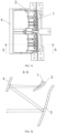
FIG. 8 is a structural schematic view of a multi-cavity reflector and a first reflector which are integrally formed, in an embodiment of the present invention; -
FIG. 9 is a structural schematic view of a second reflector in an embodiment of the present invention; -
FIG. 10 is a schematic view of an assembly structure of light-emitting light sources, the multi-cavity reflector, the first reflector and the second reflector in an embodiment of the present invention; -
FIG. 11 is a top view ofFIG. 10 ; -
FIG. 12 is an A-A sectional view ofFIG. 11 ; -
FIG. 13 is a schematic view of light shapes applied to a left vehicle lamp of an embodiment of the present invention; -
FIG. 14 is a schematic view of light shapes applied to a right vehicle lamp of an embodiment of the present invention; -
FIG. 15 is a structural schematic view of a front view when the multi-cavity reflector is applied to the left vehicle lamp in an embodiment of the present invention; -
FIG. 16 is a structural schematic view of the front view when the multi-cavity reflector is applied to the right vehicle lamp in an embodiment of the present invention; -
FIG. 17 is another structural schematic view of the front view when the multi-cavity reflector is applied to the left vehicle lamp and the right vehicle lamp in an embodiment of the present invention; -
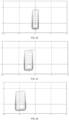
FIG. 18 is a schematic view of light shapes formed when all light-emitting light sources are turned on in the case that the multi-cavity reflector is applied to the left vehicle lamp in an embodiment of the present invention; -
FIG. 19 is a schematic view of light spots formed corresponding to a first reflection cavity counted from a left side when the multi-cavity reflector is applied to the left vehicle lamp in an embodiment of the present invention; -
FIG. 20 is a schematic view of light spots formed corresponding to a second reflection cavity counted from the left side when the multi-cavity reflector is applied to the left vehicle lamp in an embodiment of the present invention; -
FIG. 21 is a schematic view of light spots formed corresponding to a third reflection cavity counted from the left side when the multi-cavity reflector is applied to the left vehicle lamp in an embodiment of the present invention; -
FIG. 22 is a schematic view of light spots formed corresponding to a fourth reflection cavity counted from the left side when the multi-cavity reflector is applied to the left vehicle lamp in an embodiment of the present invention; -
FIG. 23 is a schematic view of light spots formed corresponding to a fifth reflection cavity counted from the left side when the multi-cavity reflector is applied to the left vehicle lamp in an embodiment of the present invention; -
FIG. 24 is a schematic view of light spots formed corresponding to a sixth reflection cavity counted from the left side when the multi-cavity reflector is applied to the left vehicle lamp in an embodiment of the present invention; -
FIG. 25 is a schematic view of the light shapes formed when the light-emitting light sources corresponding to first, third, and fifth reflection cavities counted from the left side are turned on, in the case that the multi-cavity reflector is applied to the left vehicle lamp in an embodiment of the present invention; -
FIG. 26 is a schematic view of the light shapes formed when the light-emitting light sources corresponding to second, fourth, and sixth reflection cavities counted from the left side are turned on, in the case that the multi-cavity reflector is applied to the left vehicle lamp in an embodiment of the present invention; -
FIG. 27 is a schematic view of the light shapes formed when the light-emitting light sources corresponding to first and fourth reflection cavities counted from the left side are turned on, in the case that the multi-cavity reflector is applied to the left vehicle lamp in an embodiment of the present invention; -
FIG. 28 is a structural schematic view of another embodiment of the present invention; -
FIG. 29 is aschematic view 1 of the stereoscopic structure of still another embodiment of the present invention; -
FIG. 30 is aschematic view 2 of the stereoscopic structure of yet another embodiment of the present invention; -
FIG. 31 is a side view ofFIG. 29 ; -
FIG. 32 is an optical path view of another embodiment of the present invention; and -
FIG. 33 is a structural schematic view of another embodiment of the present invention. -
- 1-light-emitting light source; 2-multi-cavity reflector;
- 21-reflection cavity; 22-partition rib;
- 3-second reflector; 31-spacer plate;
- 4-first reflector; 5-heat sink;
- 51-positioning pin; 6-circuit board;
- 7-positioning hole; 8-light shielding part;
- 9-light collimator; 91-alignment unit;
- a-high beam light shape; b-low beam light shape;
- c-low beam light-dark cut-off line.
- In the description of the present invention, it should be understood that orientation or positional relations indicated by terms such as "upper", "lower", "left", "right", and "front" are merely for facilitating the description of the present disclosure and simplifying the description, rather than indicating or implying that related devices or elements have to be in the specific orientation, or configured or operated in a specific orientation, therefore, they should not be construed as limitations on the present disclosure. In the above, "left" refers to the direction of the left hand when looking straight ahead of the car in the car, "right" refers to the direction of the right hand when looking straight ahead of the car in the car; and "upper", "lower", "front", and "rear" are all based on the orientation shown in
FIG. 2 . - The specific embodiments of the present invention will be described in detail below with reference to the drawings. It should be understood that the specific embodiments described herein are only used to illustrate and explain the present invention, but not to limit the present invention. The present invention is limited only by the appended claims.
- The present invention provides a multi-pixel high beam system, which comprises a plurality of light-emitting
light sources 1, and a light collimation element and at least one reflective element which cooperate with the light-emittinglight sources 1, wherein the light collimation element is provided with a plurality of light collimation units arranged in parallel and having set widths, the individual light-emittinglight sources 1 are respectively in one-to-one correspondence with the individual light collimation units, so that lights emitted by the individual light-emittinglight sources 1 are converged by the light collimation element, and then reflected by the reflective element to form a plurality of light spots, the plurality of light spots are arranged in sequence to form a light shape having a plurality of pixels, and widths of the individual light spots correspond to the set widths of the individual light collimation units. - It should be noted that, in the schematic views of light shapes shown in
FIG. 13 and FIG. 14 , each of grids of the high beam light shape a represents a pixel, and the high beam light shape a is formed by arranging a plurality of light spots in sequence in the left-right direction. If the individual light spots are just converged (connected) to each other, the width of the pixel is the same as the width of the corresponding light spot. However, in this case, there will be a distinct light-dark dividing line between individual pixels, which makes uniformity of the high beam light shape poor. Therefore, in order to make the convergence transition between the individual pixels even, there will be a partial overlap between the individual light spots. At this time, the width of the light spot should be larger than the width of the corresponding pixel, and the width of the light spot corresponds to the width of the corresponding light collimation unit. Therefore, in order to realize the light shape with high resolution near the area directly in front of the vehicle and low resolution in the area ot two sides in front of the vehicle as shown inFIG. 13 and FIG. 14 , light spots with different widths can be obtained by setting the widths of individual light collimation units, so as to form a multi-pixel high beam light shape having a plurality of pixels with specific widths. In the above, the area where the light shape near the area directly in front of the vehicle is projected on the light distribution screen is the light shape central area in the schematic views of light shapes shown inFIG. 13 and FIG. 14 (the area where the intersection of the horizontal 0-degree line and the vertical 0-degree line is located), and the area where the light shapes at the two sides in front of the vehicle are projected on the light distribution screen is the outer region of the light shapes in the schematic views of light shapes shown inFIG. 13 and FIG. 14 . - The light collimation element of the present invention is provided with a plurality of light collimation units arranged in parallel and having set widths, so that the lights emitted by the individual light-emitting
light sources 1 can be collected and converged by the light collimation element, and reflected by the reflective element to form a high beam light shape having a plurality of pixels with specific widths, and by setting the widths of individual light collimation units of the light collimation element, light spots with widths corresponding to the widths of individual light collimation units can be formed, thereby forming a plurality of pixels with specific widths, so that the width of each of pixels can be adjusted, so as to set the width of a single pixel separately according to the actual condition on a vehicle driving road, thereby meeting the multi-pixel intelligent illumination requirements. - As a specific embodiment, as shown in
FIG. 1 to FIG. 3 , the light collimation element is amulti-cavity reflector 2, and themulti-cavity reflector 2 includes a plurality ofreflection cavities 21 arranged in parallel and having set widths, wherein thereflection cavities 21 are the light collimation units on the above-mentioned light collimation element. In the above, two reflective elements are provided, which are afirst reflector 4 and asecond reflector 3 respectively. Thefirst reflector 4 is provided directly in front of themulti-cavity reflector 2, thesecond reflector 3 is located below themulti-cavity reflector 2, and the lights emitted by the individual light-emittinglight sources 1 are collected and converged by themulti-cavity reflector 2, and then reflected by thefirst reflector 4 and thesecond reflector 3 in sequence to form a high beam light shape having a plurality of pixels. By arranging thefirst reflector 4 and thesecond reflector 3, the incident and exit directions of the lights can be better adjusted through multi-level reflection, so as to better form the expected high beam light shape, and make the structure of the present invention more compact. - Specifically, as shown in
FIG. 6 to FIG. 8 andFIG. 10 to FIG. 12 , the reflection surfaces of theindividual reflection cavities 21 are all paraboloids, and the individual light-emittinglight sources 1 are respectively provided on focal points of theindividual reflection cavities 21 in a one-to-one correspondence. By providing the paraboloidal reflection surfaces, most of the lights emitted by the light-emittinglight sources 1 can be collected and converged and reflected to thefirst reflector 4, thereby improving the light efficiency. Of course, the reflection surfaces of theindividual reflection cavities 21 may also be cambered reflection surfaces such as arc-shaped surfaces, and ellipsoid surfaces, as long as they can collect and converge the lights emitted by the light-emittinglight sources 1 and reflect them to thefirst reflector 4. - In the above, since the
individual reflection cavities 21 are arranged in parallel, preferably, apartition rib 22 is provided between eachadjacent reflection cavities 21 to separate them from each other, in order to prevent the formation of stray light due to the phenomenon of light channeling betweenadjacent reflection cavities 21 which affects the formation of the expected light shape,. - In the above, the
multi-cavity reflector 2 includes eightreflection cavities 21, and the widths ofindividual reflection cavities 21 can be adjusted according to the actual light distribution and the widths of the light spots that need to be obtained. When they are practically applied to vehicle lamp, it is necessary to form a high beam light shape with wide pixel width (low resolution) in the outer region of the light shape and narrow pixel width (high resolution) in the central area of the light shape, hence, when they are applied to the left vehicle lamp, the widths ofindividual reflection cavities 21 from right to left are set to correspond to the widths of individual pixels inFIG.13 from left to right, wherein, inFIG. 13 , a refers to the high beam light shape with eight pixels, b refers to the low beam light shape, and c refers to the low beam light-dark cut-off line. The widths of the eight pixels inFIG. 13 gradually decrease from the left (outer region of the light shape) to the right (the central region of the light shape), and in theory, the widths ofindividual reflection cavities 21 are set to have a trend of decreasing gradually from right to left. However, for the uniform convergence (connection) between the pixels, the individual light spots are made to be partially superimposed, the widths ofindividual reflection cavities 21 as shown inFIG. 11 can be set according to the widths of the light spots that need to be obtained, and do not necessarily have a trend of gradual change in size, as long as a light shape in which the pixel widths gradually decrease from the outer region of the light shape to the central region of the light shape can be obtained, after individual light spots are finally arranged. When they are applied to the right vehicle lamp, the widths ofindividual reflection cavities 21 from right to left are set to correspond to the widths of individual pixels inFIG.14 from left to right, wherein inFIG. 14 , a refers to the high beam light shape with eight pixels, b refers to the low beam light shape, and c refers to the low beam light-dark cut-off line. The widths of the eight pixels inFIG. 14 gradually increase from the left (the central region of the light shape) to the right (the outer region of the light shape), and in theory, the widths ofindividual reflection cavities 21 are set to have a trend of increasing gradually from right to left. However, similarly, for the uniform convergence between the pixels, the widths ofindividual reflection cavities 21 can be set according to the widths of the light spots that need to be obtained, and do not necessarily have a trend of gradual change in size, as long as a light shape in which the pixel widths gradually decrease from the outer region of the light shape to the central region of the light shape can be obtained, after individual light spots are finally arranged. In this way, after the exiting light shapes of the left and right vehicle lamps are superimposed, a high beam light shape with wide pixel width (low resolution) in the outer region of the light shape and narrow pixel width (high resolution) in the central region of the light shape can be formed. - Of course, the width setting of the
multiple reflection cavities 21 of themulti-cavity reflector 2 can be implemented in different ways, and in all case, a high beam light shape with wide pixel width (low resolution) in the outer region of the light shape and narrow pixel width (high resolution) in the central region of the light shape can be formed after the exiting light shapes of the left and right vehicle lamps are superimposed. Referring toFIG. 15 to FIG. 17 ,FIG. 15 is a structural schematic view of a front view when themulti-cavity reflector 2 is applied to the left vehicle lamp (that is, the view structure presented when seeing from the front of the vehicle to the inside of the vehicle in the case that themulti-cavity reflector 2 is installed in the left vehicle lamp), the widths of thefirst reflection cavity 21, thesecond reflection cavity 21, thethird reflection cavity 21 and thefourth reflection cavity 21 counted from the left side thereof are not much different, and the width of thefifth reflection cavity 21 is larger than that of thefourth reflection cavity 21, and the width of thesixth reflection cavity 21 is greater than the width of thefifth reflection cavity 21. The overall exiting light shape formed on the light distribution screen is specifically shown inFIG. 18 , andFIG. 19 toFIG. 24 show the corresponding light spots formed after the lights emitted by individual light-emittinglight sources 1 are reflected by thecorresponding reflection cavities 21 and reflected by the reflective element. It can be seen from the figure that the individual light spots will be partially overlapped after arranged in sequence, and widths of the formed light spot corresponding to thefirst reflection cavity 21, the formed light spot corresponding to thesecond reflection cavity 21, the formed light spot corresponding to thethird reflection cavity 21, and the formed light spot corresponding to thefourth reflection cavity 21 are not much different, the width of the formed light spot corresponding to thefifth reflection cavity 21 is larger than the width of the formed light spot corresponding to thefourth reflection cavity 21, the width of the formed light spot corresponding to thesixth reflection cavity 21 is larger than the width of the formed light spot corresponding to thefifth reflection cavity 21, and the widths of the light spots are in one-to-one correspondence with the widths of the remainingindividual reflection cavities 21. As shown inFIG. 25 , from the schematic view of the light shapes formed by turning off the light-emittinglight sources 1 corresponding to the second, fourth andsixth reflection cavities 21, it can be seen that the width of the dark area between the formed light spot corresponding to thethird reflection cavity 21 and the formed light spot corresponding to thefifth reflection cavity 21 is the pixel width corresponding to thefourth reflection cavity 21, which is larger than the pixel width corresponding to thesecond reflection cavity 21 located on the right side thereof (that is, the width of the dark area between the formed light spot corresponding to thefirst reflection cavity 21 and the formed light spot corresponding to the third reflection cavity 21). As shown inFIG. 26 , similarly, the pixel width corresponding to thefifth reflection cavity 21 is larger than the pixel width corresponding to thethird reflection cavity 21 located on the right side thereof. CombiningFIG. 25 and FIG. 26 , it can be seen that the pixel width corresponding to thefifth reflection cavity 21 is larger than the pixel width corresponding to thefourth reflection cavity 21 located on the right side thereof, and the pixel width corresponding to thefourth reflection cavity 21 is larger than the pixel width corresponding to thethird reflection cavity 21 located on the right side thereof. The pixel width corresponding to thethird reflection cavity 21 is similar to the pixel width corresponding to thesecond reflection cavity 21 located on right side thereof, which conforms to the characteristic that the pixel width of the light shape exited from the left vehicle lamp gradually decreases from the outer region of the light shape to the central region of the light shape.FIG. 16 is a structural schematic view of a front view when themulti-cavity reflector 2 applied to the right vehicle lamp, the variation rule of the width of thereflection cavity 21 thereof is opposite to the variation rule of the width of thereflection cavity 21 shown inFIG. 15 . The light shape exited from the right vehicle lamp and having the pixel width gradually decreasing from the outer region of the light shape to the central region of the light shape is formed on the light distribution screen, and the light shape exited from the left vehicle lamp and the light shape exited from the right vehicle lamp are superimposed and then form a high beam light shape with wide pixel width at two sides and narrow pixel width in the middle.FIG. 17 is another structural schematic view of a front view when themulti-cavity reflectors 2 are applied to the left vehicle lamp and the right vehicle lamp, wherein the structures of themulti-cavity reflectors 2 applied to the left vehicle lamp and the right vehicle lamp are the same, the widths of thereflective cavities 21 thereof gradually decrease from the two sides to the middle. After the light shapes exited from the left and right vehicle lamps are superimposed, a high beam light shape with wide pixel width at two sides and narrow pixel width in the middle can also be formed similarly. - Preferably, as shown in
FIG. 25 to FIG. 27 , each of the light-emittinglight sources 1 is a single-chip light-emitting light source and can be lit independently, such that in practical application, by controlling the on and off of individual light-emitting light sources, the brightness and darkness of the corresponding pixel can be realized, so that the self-adaptive high beam illumination can be flexibly realized. - In the above embodiment, specifically, a reflection surface of the
first reflector 4 is a plane, and thefirst reflector 4 is obliquely provided directly in front of themulti-cavity reflector 2 from top to bottom in a direction away from the lighting-emittinglight source 1, so that the lights converged and reflected by themulti-cavity reflector 2 is made to be incident on the reflection surface of thesecond reflector 3 after being reflected by thefirst reflector 4. By setting the reflection surface of thefirst reflector 4 as a plane, the exit direction of the light can be better controlled to ensure that more light is incident on the reflection surface of thesecond reflector 3. Of course, the reflection surface of thefirst reflector 4 can also be other curved surfaces that can reflect light. - Specifically, as shown in
FIG. 9 , thesecond reflector 3 includes two reflection surfaces with a segment difference, that is, thesecond reflector 3 is formed by splicing two reflection surfaces with the segment difference, and the two reflection surfaces are preferably paraboloidic reflection surface. The two reflection surfaces correspond to one focal point respectively, which enables better light shape effect compared with the case in which one reflection surface with one focal point is used, and simultaneously, if the reflection surface of thesecond reflector 3 is a whole reflection surface, the width of the reflection surface in the left-right direction needs to be large to ensure that the required light shape can be obtained, while if the reflection surface is divided into two reflection surfaces, the two reflection surfaces can be subjected to respective design and adjustment, so that the reflection surface of thesecond reflector 3 does not need to be large to form an expected light shape. In addition, since thesecond reflector 3 has two reflection surfaces, aspacer plate 31 is provided between the two reflection surfaces, in order to prevent light channeling from affecting the light efficiency. - Preferably, a
light shielding part 8 configured to shield a part of direct lights incident on themulti-cavity reflector 2 is provided in front of the light-emittinglight sources 1, and thelight shielding part 8 is located above themulti-cavity reflector 2. If this part of the direct lights are reflected by themulti-cavity reflector 2 and reflective element in sequence to the front of the vehicle, this part of the direct lights will cause dazzling pedestrians or oncoming car drivers, which is prone to causing traffic accidents; thelight shielding part 8 can also prevent the scattered or diffused lights from the light-emittinglight sources 1 from being projected towards a specific area of themulti-cavity reflector 2, so as to avoid the appearance of unwanted light and glare other than the light shape pattern expected to be obtained. As shown inFIG. 7 , thelight shielding part 8 is in a plate-like structure, and thelight shielding part 8 is preferably integrally formed with theheat sink 5, so that no additional installation structure is required, and the structure is more compact. - As another specific embodiment, as shown in
FIG. 28 , the light collimation element is amulti-cavity reflector 2, and themulti-cavity reflector 2 comprises a plurality ofreflection cavities 21 arranged in parallel and having set widths. Two reflective elements are provided, which are respectively afirst reflector 4 and asecond reflector 3, wherein thefirst reflector 4 is provided directly in front of themulti-cavity reflector 2, and thesecond reflector 3 is located above themulti-cavity reflector 2, and lights emitted by the individual light-emittinglight sources 1 are collected and converged by themulti-cavity reflector 2, and then reflected by thefirst reflector 4 and thesecond reflector 3 in sequence to form a high beam light shape having a plurality of pixels. - In the above, since the
second reflector 3 is located above themulti-cavity reflector 2, thefirst reflector 4 is obliquely provided directly in front of themulti-cavity reflector 2 from top to bottom in a direction close to the light-emittinglight source 1, in order that the lights converged and reflected by themulti-cavity reflector 2 can be incident on the reflection surface of thesecond reflector 3 after being reflected through thefirst reflector 4. - As another specific embodiment, as shown in
FIG. 29 to FIG. 32 , the light collimation element is alight collimator 9, and thelight collimator 9 comprises a plurality ofalignment units 91 arranged in parallel. Light incident ends of theindividual alignment units 91 are separated from each other, and the light incident ends of theindividual alignment units 91 are in one-to-one correspondence with the individual light-emittinglight sources 1, light exit ends of theindividual alignment units 91 are connected with each other to constitute a light exit surface, wherein end surfaces of the light exit ends of theindividual alignment units 91 respectively have set widths to form the above-mentioned light collimation unit. Two reflective elements are provided, which are respectively afirst reflector 4 and asecond reflector 3, wherein thefirst reflector 4 is provided directly in front of thelight collimator 9, and thesecond reflector 3 is located below thelight collimator 9. Of course, thesecond reflector 3 may be also located above thelight collimator 9, and lights emitted by the individual light-emittinglight sources 1 are converged by thelight collimator 9, and then reflected by thefirst reflector 4 and thesecond reflector 3 in sequence to form a high beam light shape having a plurality of pixels. - As another specific embodiment, as shown in
FIG. 33 , one reflective element is provided, which is asecond reflector 3, and thesecond reflector 3 is provided below themulti-cavity reflector 2. By providing one reflective element, it is also possible to form a high beam light shape having a plurality of pixels with specific widths. It should be understood that the selection of the number of reflective elements is related to the light shape to be formed. The reflective elements can properly diffuse the light, and the number of the reflective elements and the relative positions of reflective elements need to be selected according to light distribution requirements. - In the above-mentioned embodiments, preferably, each of the light-emitting
light sources 1 is provided on acircuit board 6, and the light collimation element, the reflective elements and thecircuit board 6 are all fixed on aheat sink 5. - As a specific assembly embodiment, as shown in
FIG. 4 to FIG. 7 , the light collimation element is amulti-cavity reflector 2, and two reflective elements are provided, which are afirst reflector 4 and asecond reflector 3 respectively. Thefirst reflector 4 is provided directly in front of themulti-cavity reflector 2, and thesecond reflector 3 is located below themulti-cavity reflector 2, wherein themulti-cavity reflector 2 and thefirst reflector 4 are preferably integrally formed, which can make the structure more compact and the installation more convenient. The two ends of the integrally molded part are respectively provided with apositioning hole 7 and a fixed hole, the two ends of thesecond reflector 3 are respectively provided with apositioning hole 7 and a fixed hole, thecircuit board 6 on which the light-emittinglight sources 1 are installed is also provided withpositioning holes 7 and fixed holes, and corresponding positions on theheat sink 5 are provided with bolt holes matched (cooperating) with the individual fixed holes and positioning pins 51 matched (cooperating) with the individual positioning holes 7. During assembly, thecircuit board 6 on which the light-emittinglight sources 1 are installed is first positioned and placed on theheat sink 5, even if the positioning pins 51 on theheat sink 5 pass through the positioning holes 7 of thecircuit board 6, and then the integrally molded part of themulti-cavity reflector 2 and thefirst reflector 4, and thesecond reflector 3 are respectively positioned and installed on theheat sink 5 through cooperating of the positioning holes 7 and the positioning pins 51, and finally tightened and fixed by bolts, so that thecircuit board 6 on which the light-emittinglight sources 1 are installed, the integrally molded part of themulti-cavity reflector 2 and thefirst reflector 4, and thesecond reflector 3 are respectively positioned and fixedly installed on theheat sink 5. - The present invention also provides a vehicle lamp, which includes the above-mentioned multi-pixel high beam system.
- By arranging the multi-pixel high beam system, the vehicle lamp can form a high beam light shape having a plurality of pixels with specific widths, and the width of each pixel can be independently set according to the actual condition on a vehicle driving road, thereby meeting the multi-pixel intelligent illumination requirements of the vehicle lamp.
- Correspondingly, the present invention also provides a vehicle, which includes the above-mentioned vehicle lamp.
- By arranging the vehicle lamp, the vehicle can form a high beam light shape having a plurality of pixels with specific widths, and the width of each pixel can be independently set according to the actual condition on a vehicle driving road, thereby meeting the multi-pixel intelligent illumination requirements of the vehicle.
Claims (12)
- A multi-pixel high beam system, comprising a plurality of light-emitting light sources (1), and a light collimation element and at least one reflective element which cooperate with the light-emitting light sources (1), wherein the light collimation element is provided with a plurality of light collimation units arranged in parallel and having set widths, the individual light-emitting light sources (1) are respectively in one-to-one correspondence with the individual light collimation units, so that lights emitted by the individual light-emitting light sources (1) are converged by the light collimation element, and then reflected by the reflective element to form a plurality of light spots, the plurality of light spots are arranged in sequence to form a light shape having a plurality of pixels, and widths of the individual light spots correspond to the set widths of the individual light collimation units; wherein two reflective elements are provided, which are respectively a first reflector (4) and a second reflector (3), wherein the first reflector (4) is provided directly in front of the light collimation element, and the second reflector (3) is located above or below the light collimation element, wherein lights emitted by the individual light-emitting light sources (1) are converged by the light collimation element, and then reflected by the first reflector (4) and the second reflector (3) in sequence to form the light shape having the plurality of pixels;
characterised in that;the second reflector (3) comprises two reflection surfaces with a segment difference, and a spacer plate (31) is provided between the two reflection surfaces; andwherein the two reflection surfaces correspond to one focal point, respectively. - The multi-pixel high beam system according to claim 1, wherein widths of the plurality of pixels gradually decrease from an outer region of the light shape to a central region of the light shape.
- The multi-pixel high beam system according to claim 1, wherein the light collimation element is a multi-cavity reflector (2), the multi-cavity reflector (2) comprises a plurality of reflection cavities (21) arranged in parallel and having set widths, and the reflection cavities (21) are formed as the light collimation units.
- The multi-pixel high beam system according to claim 3, wherein reflection surfaces of the individual reflection cavities (21) are all paraboloids, and the individual light-emitting light sources (1) are respectively provided on focal points of the individual reflection cavities (21) in a one-to-one correspondence, and a partition rib (22) is provided between each adjacent reflection cavities (21).
- The multi-pixel high beam system according to claim 3, wherein a light shielding part (8) configured to shield a part of direct lights is provided in front of the light-emitting light sources (1).
- The multi-pixel high beam system according to claim 1, wherein the light collimation element is a light collimator (9), and the light collimator (9) comprises a plurality of alignment units (91) arranged in parallel, light incident ends of the individual alignment units (91) are separated from each other, the light incident ends of the individual alignment units (91) are in one-to-one correspondence with the individual light-emitting light sources (1), and light exit ends of the individual alignment units (91) are connected with each other to constitute a light exit surface, wherein end surfaces of the light exit ends of the individual alignment units (91) respectively have set widths to form the light collimation units.
- The multi-pixel high beam system according to claim 1, wherein a reflection surface of the first reflector (4) is a plane, and the first reflector (4) is obliquely provided directly in front of the light collimation element.
- The multi-pixel high beam system according to claim 1, wherein the first reflector (4) and the light collimation element are integrally formed.
- The multi-pixel high beam system according to any one of claims 1 to 8, wherein each of the individual light-emitting light sources (1) is a single-chip light-emitting light source and can be lit independently.
- The multi-pixel high beam system according to any one of claims 1 to 8, wherein each of the light-emitting light sources (1) is provided on a circuit board (6), and the light collimation element, the reflective elements and the circuit board (6) are all fixed on a heat sink (5).
- A vehicle lamp, comprising the multi-pixel high beam system according to any one of claims 1 to 10.
- A vehicle, comprising the vehicle lamp according to claim 11.
Applications Claiming Priority (2)
| Application Number | Priority Date | Filing Date | Title |
|---|---|---|---|
| CN202010444135.2A CN113701120A (en) | 2020-05-22 | 2020-05-22 | Multi-pixel far-light system, car lamp and car |
| PCT/CN2021/079107 WO2021232885A1 (en) | 2020-05-22 | 2021-03-04 | Multi-pixel high beam system, vehicle lamp, and vehicle |
Publications (4)
| Publication Number | Publication Date |
|---|---|
| EP4123218A1 EP4123218A1 (en) | 2023-01-25 |
| EP4123218A4 EP4123218A4 (en) | 2023-01-25 |
| EP4123218C0 EP4123218C0 (en) | 2024-02-14 |
| EP4123218B1 true EP4123218B1 (en) | 2024-02-14 |
Family
ID=78646426
Family Applications (1)
| Application Number | Title | Priority Date | Filing Date |
|---|---|---|---|
| EP21809111.4A Active EP4123218B1 (en) | 2020-05-22 | 2021-03-04 | Multi-pixel high beam system, vehicle lamp, and vehicle |
Country Status (3)
| Country | Link |
|---|---|
| EP (1) | EP4123218B1 (en) |
| CN (1) | CN113701120A (en) |
| WO (1) | WO2021232885A1 (en) |
Family Cites Families (8)
| Publication number | Priority date | Publication date | Assignee | Title |
|---|---|---|---|---|
| TWI364121B (en) * | 2008-09-22 | 2012-05-11 | Ind Tech Res Inst | A collimating element of a light-emitting diode |
| TWI375110B (en) * | 2008-10-31 | 2012-10-21 | Hon Hai Prec Ind Co Ltd | Light source device and projector using same |
| CN107420825B (en) | 2017-09-27 | 2023-07-14 | 华域视觉科技(上海)有限公司 | Intelligent high beam illumination optical module and intelligent high beam illumination optical unit |
| CN109973921A (en) * | 2019-04-15 | 2019-07-05 | 华域视觉科技(上海)有限公司 | Car light mould group |
| CN110030532B (en) * | 2019-05-14 | 2023-10-20 | 华域视觉科技(上海)有限公司 | Lighting system and vehicle |
| CN110186008A (en) * | 2019-06-05 | 2019-08-30 | 华域视觉科技(上海)有限公司 | Car lighting unit and car lighting car light |
| CN111076141A (en) * | 2019-12-04 | 2020-04-28 | 华域视觉科技(上海)有限公司 | Car light module and car light |
| CN212339144U (en) * | 2020-05-22 | 2021-01-12 | 华域视觉科技(上海)有限公司 | Multi-pixel far-light system, car lamp and car |
-
2020
- 2020-05-22 CN CN202010444135.2A patent/CN113701120A/en active Pending
-
2021
- 2021-03-04 EP EP21809111.4A patent/EP4123218B1/en active Active
- 2021-03-04 WO PCT/CN2021/079107 patent/WO2021232885A1/en unknown
Also Published As
| Publication number | Publication date |
|---|---|
| EP4123218C0 (en) | 2024-02-14 |
| EP4123218A1 (en) | 2023-01-25 |
| CN113701120A (en) | 2021-11-26 |
| WO2021232885A1 (en) | 2021-11-25 |
Similar Documents
| Publication | Publication Date | Title |
|---|---|---|
| CN108253372B (en) | Light module for a motor vehicle headlight | |
| US7441928B2 (en) | Lighting device | |
| EP1794491B1 (en) | Led collimator element with an asymmetrical collimator | |
| EP2620697B1 (en) | Vehicle lighting unit with projection lens and led | |
| CN112781004A (en) | Vehicle lamp | |
| US7997778B2 (en) | Vehicle light | |
| KR102611832B1 (en) | Vehicle lamp lighting modules, vehicle lamps and vehicles | |
| JP7404532B2 (en) | Vehicle lamp module and vehicle lamp | |
| US6367954B1 (en) | Multi-lens projector lamp | |
| EP3460319B1 (en) | Light-emitting module and vehicle lamp | |
| CN210740255U (en) | Car light optical element, car light module, vehicle headlamp and vehicle | |
| CN212339144U (en) | Multi-pixel far-light system, car lamp and car | |
| EP4123218B1 (en) | Multi-pixel high beam system, vehicle lamp, and vehicle | |
| WO2022068504A1 (en) | Automotive headlamp system and automotive lamp | |
| WO2022099956A1 (en) | Vehicle headlamp system and vehicle lamp | |
| US11841122B2 (en) | Motor vehicle light module comprising an electrochromic device | |
| US11946609B2 (en) | Vehicle lamp | |
| EP4206524A1 (en) | Optical reflection system for vehicle lamp lighting device, and vehicle lamp lighting device | |
| CN220321117U (en) | Lighting module and car light | |
| EP4321794A1 (en) | Illumination module with multi light sources and headlight having the same | |
| CN218268854U (en) | Car light module, car light and car | |
| WO2023162906A1 (en) | Vehicle lamp | |
| KR20190048553A (en) | Lamp for vehicle | |
| JP7101547B2 (en) | Vehicle headlights | |
| CN115875629A (en) | High-beam and low-beam integrated lighting device and car lamp |
Legal Events
| Date | Code | Title | Description |
|---|---|---|---|
| STAA | Information on the status of an ep patent application or granted ep patent |
Free format text: STATUS: THE INTERNATIONAL PUBLICATION HAS BEEN MADE |
|
| PUAI | Public reference made under article 153(3) epc to a published international application that has entered the european phase |
Free format text: ORIGINAL CODE: 0009012 |
|
| STAA | Information on the status of an ep patent application or granted ep patent |
Free format text: STATUS: REQUEST FOR EXAMINATION WAS MADE |
|
| STAA | Information on the status of an ep patent application or granted ep patent |
Free format text: STATUS: EXAMINATION IS IN PROGRESS |
|
| 17P | Request for examination filed |
Effective date: 20221019 |
|
| A4 | Supplementary search report drawn up and despatched |
Effective date: 20221216 |
|
| AK | Designated contracting states |
Kind code of ref document: A1 Designated state(s): AL AT BE BG CH CY CZ DE DK EE ES FI FR GB GR HR HU IE IS IT LI LT LU LV MC MK MT NL NO PL PT RO RS SE SI SK SM TR |
|
| 17Q | First examination report despatched |
Effective date: 20230110 |
|
| DAV | Request for validation of the european patent (deleted) | ||
| DAX | Request for extension of the european patent (deleted) | ||
| GRAP | Despatch of communication of intention to grant a patent |
Free format text: ORIGINAL CODE: EPIDOSNIGR1 |
|
| STAA | Information on the status of an ep patent application or granted ep patent |
Free format text: STATUS: GRANT OF PATENT IS INTENDED |
|
| RIC1 | Information provided on ipc code assigned before grant |
Ipc: F21W 102/145 20180101ALN20230901BHEP Ipc: F21S 45/47 20180101ALI20230901BHEP Ipc: F21S 41/39 20180101ALI20230901BHEP Ipc: F21S 41/365 20180101ALI20230901BHEP Ipc: F21S 41/151 20180101ALI20230901BHEP Ipc: F21S 41/148 20180101ALI20230901BHEP Ipc: F21S 41/43 20180101ALI20230901BHEP Ipc: F21S 41/24 20180101ALI20230901BHEP Ipc: F21S 41/32 20180101ALI20230901BHEP Ipc: F21S 41/663 20180101ALI20230901BHEP Ipc: F21S 41/30 20180101AFI20230901BHEP |
|
| INTG | Intention to grant announced |
Effective date: 20231004 |
|
| GRAS | Grant fee paid |
Free format text: ORIGINAL CODE: EPIDOSNIGR3 |
|
| GRAA | (expected) grant |
Free format text: ORIGINAL CODE: 0009210 |
|
| STAA | Information on the status of an ep patent application or granted ep patent |
Free format text: STATUS: THE PATENT HAS BEEN GRANTED |
|
| AK | Designated contracting states |
Kind code of ref document: B1 Designated state(s): AL AT BE BG CH CY CZ DE DK EE ES FI FR GB GR HR HU IE IS IT LI LT LU LV MC MK MT NL NO PL PT RO RS SE SI SK SM TR |
|
| REG | Reference to a national code |
Ref country code: GB Ref legal event code: FG4D |
|
| REG | Reference to a national code |
Ref country code: CH Ref legal event code: EP |
|
| REG | Reference to a national code |
Ref country code: DE Ref legal event code: R096 Ref document number: 602021009461 Country of ref document: DE |
|
| REG | Reference to a national code |
Ref country code: IE Ref legal event code: FG4D |
|
| U01 | Request for unitary effect filed |
Effective date: 20240214 |
|
| U07 | Unitary effect registered |
Designated state(s): AT BE BG DE DK EE FI FR IT LT LU LV MT NL PT SE SI Effective date: 20240222 |