EP4120979B1 - Ohreinsatz - Google Patents
Ohreinsatz Download PDFInfo
- Publication number
- EP4120979B1 EP4120979B1 EP21714356.9A EP21714356A EP4120979B1 EP 4120979 B1 EP4120979 B1 EP 4120979B1 EP 21714356 A EP21714356 A EP 21714356A EP 4120979 B1 EP4120979 B1 EP 4120979B1
- Authority
- EP
- European Patent Office
- Prior art keywords
- open end
- ear
- insert
- funnel
- ear insert
- Prior art date
- Legal status (The legal status is an assumption and is not a legal conclusion. Google has not performed a legal analysis and makes no representation as to the accuracy of the status listed.)
- Active
Links
Images

Classifications
-
- A—HUMAN NECESSITIES
- A61—MEDICAL OR VETERINARY SCIENCE; HYGIENE
- A61F—FILTERS IMPLANTABLE INTO BLOOD VESSELS; PROSTHESES; DEVICES PROVIDING PATENCY TO, OR PREVENTING COLLAPSING OF, TUBULAR STRUCTURES OF THE BODY, e.g. STENTS; ORTHOPAEDIC, NURSING OR CONTRACEPTIVE DEVICES; FOMENTATION; TREATMENT OR PROTECTION OF EYES OR EARS; BANDAGES, DRESSINGS OR ABSORBENT PADS; FIRST-AID KITS
- A61F11/00—Methods or devices for treatment of the ears or hearing sense; Non-electric hearing aids; Methods or devices for enabling ear patients to achieve auditory perception through physiological senses other than hearing sense; Protective devices for the ears, carried on the body or in the hand
- A61F11/06—Protective devices for the ears
- A61F11/08—Protective devices for the ears internal, e.g. earplugs
-
- H—ELECTRICITY
- H04—ELECTRIC COMMUNICATION TECHNIQUE
- H04R—LOUDSPEAKERS, MICROPHONES, GRAMOPHONE PICK-UPS OR LIKE ACOUSTIC ELECTROMECHANICAL TRANSDUCERS; ELECTRIC HEARING AIDS; PUBLIC ADDRESS SYSTEMS
- H04R1/00—Details of transducers, loudspeakers or microphones
- H04R1/10—Earpieces; Attachments therefor ; Earphones; Monophonic headphones
- H04R1/1016—Earpieces of the intra-aural type
-
- A—HUMAN NECESSITIES
- A61—MEDICAL OR VETERINARY SCIENCE; HYGIENE
- A61F—FILTERS IMPLANTABLE INTO BLOOD VESSELS; PROSTHESES; DEVICES PROVIDING PATENCY TO, OR PREVENTING COLLAPSING OF, TUBULAR STRUCTURES OF THE BODY, e.g. STENTS; ORTHOPAEDIC, NURSING OR CONTRACEPTIVE DEVICES; FOMENTATION; TREATMENT OR PROTECTION OF EYES OR EARS; BANDAGES, DRESSINGS OR ABSORBENT PADS; FIRST-AID KITS
- A61F11/00—Methods or devices for treatment of the ears or hearing sense; Non-electric hearing aids; Methods or devices for enabling ear patients to achieve auditory perception through physiological senses other than hearing sense; Protective devices for the ears, carried on the body or in the hand
- A61F11/06—Protective devices for the ears
- A61F11/08—Protective devices for the ears internal, e.g. earplugs
- A61F11/085—Protective devices for the ears internal, e.g. earplugs including an inner channel
-
- A—HUMAN NECESSITIES
- A61—MEDICAL OR VETERINARY SCIENCE; HYGIENE
- A61F—FILTERS IMPLANTABLE INTO BLOOD VESSELS; PROSTHESES; DEVICES PROVIDING PATENCY TO, OR PREVENTING COLLAPSING OF, TUBULAR STRUCTURES OF THE BODY, e.g. STENTS; ORTHOPAEDIC, NURSING OR CONTRACEPTIVE DEVICES; FOMENTATION; TREATMENT OR PROTECTION OF EYES OR EARS; BANDAGES, DRESSINGS OR ABSORBENT PADS; FIRST-AID KITS
- A61F11/00—Methods or devices for treatment of the ears or hearing sense; Non-electric hearing aids; Methods or devices for enabling ear patients to achieve auditory perception through physiological senses other than hearing sense; Protective devices for the ears, carried on the body or in the hand
- A61F11/30—Non-electric hearing aids, e.g. ear trumpets, sound amplifiers or ear-shells
-
- H—ELECTRICITY
- H04—ELECTRIC COMMUNICATION TECHNIQUE
- H04R—LOUDSPEAKERS, MICROPHONES, GRAMOPHONE PICK-UPS OR LIKE ACOUSTIC ELECTROMECHANICAL TRANSDUCERS; ELECTRIC HEARING AIDS; PUBLIC ADDRESS SYSTEMS
- H04R25/00—Electric hearing aids
- H04R25/65—Housing parts, e.g. shells, tips or moulds, or their manufacture
- H04R25/652—Ear tips; Ear moulds
Definitions
- This invention relates generally to an ear insert for insertion in an ear and, more particularly to an ear waveguide device for reducing sound distortion caused by resonance within the ear canal.
- the human ear has three distinguishable parts, namely the outer, middle and inner ear.
- the outer ear consists of the visible portion called the auricle or pinna which projects from the side of the head.
- the middle ear is a narrow, air-filled cavity known as the ear canal leading from the outer ear to the inner ear, the inner end of the ear canal being closed by a tympanic membrane so as to form a boundary between the middle ear and the inner ear.
- the outer ear is shaped to form an irregular shallow funnel, with a depression known as the concha leading directly to the entrance of the ear canal.
- the concha is partly covered by two small projections, the tongue-like tragus in front and the antitragus behind.
- the function of the outer ear is to collect sound waves and guide them, via the ear canal, to the tympanic membrane.
- the outer ear acts to 'funnel' sound waves from a listener's vicinity into the ear canal.
- the ear canal is essentially a tube that is open at one end (the concha region) and closed at the other end (tympanic membrane).
- the air inside the ear canal acts as a resonating body.
- the natural resonant frequency of the ear canal is four times its length ( ⁇ 25mm average for an adult) and, therefore, it acts as a quarter-wave resonator and amplifies sound waves.
- noise i.e. intrusive or unwanted sound that disrupts, distracts or detracts from regular functioning
- the vagus nerve together with the parasympathetic nervous system, is responsible for (amongst other things) triggering the human fight-or-flight stress response. It follows, therefore. That noise can trigger the fight-or-flight response and cause stress.
- noise distortion created by the geometry of the concha and amplified (especially at frequencies above ⁇ 1.5kHz) within the ear canal can cause the Vagus nerve to trigger the fight-or-flight stress response.
- US Patent Application Publication US2014/138179A1 describes an earphone including a tubular sidewall having an inner surface defining an air channel extending through the sidewall, that redirects sound at an angle to the speaker axis, and has a smooth contour to maintain sound quality.
- European Patent Application EP2809081A1 describes a headphone having a driver unit fixed to a housing and a nozzle inclined by a predetermined angel toward its distal portion.
- the nozzle section is curved so as to swell inwardly or outwardly.
- US Patent Application Publication US2017/065457A1 describes a hearing aid having a body and a funneled sound collector.
- UK Patent Application GB16423A describes a hearing appliance comprising a hollow permanent magnet attached to a tapered holder.
- European Patent Application EP1937031A1 describes an earbud comprising a coupling having a tapered elastomeric sleeve having a rear end that can be expanded to fit around the periphery of the earbud front.
- an ear insert which has a generally funnel-shaped wall defining a tapering channel extending between first and second open ends, the first open end having a diameter or width greater than that of the second open end, wherein a portion of the funnel-shaped wall immediately adjacent the second open end is configured to enable the ear insert to be located within the opening of a user's ear canal, for use, with the first open end adjacent the user's tragus and the second open end facing the user's tympanic membrane, at least a portion of the tapering channel comprising an acoustic wave reflecting region that extends from a location at or near the first open end toward the second open end at an angle of between 60° and 75° relative to a lateral plane defined by the edge of the funnel-shaped wall at the first open end, characterised in that the acoustic wave reflecting region comprises a substantially planar surface.
- the acoustic wave reflecting region extends from a location at or near the first open end toward the second open end at an angle of between 65° and 70°, and optionally between 62° and 63°, relative to the lateral plane defined by the edge of the funnel-shaped wall at the first open end.
- the ear insert may be configured to fit onto or over an ear bud of in-ear headphones.
- the ear insert may be shaped and configured at the second open end to receive and retain a resilient tip.
- the portion of the funnel-shaped wall immediately adjacent the second open end may comprise a generally tubular portion having a longitudinal axis extending at an angle relative to the lateral plane defined by the edge of the funnel-shaped wall at the first open end, the second open end being at the distal end of the tubular portion.
- the longitudinal axis of the generally tubular portion may extend at an angle of between 40° and 50°, e.g. substantially 45°, relative to the lateral plane defined by the edge of the funnel-shaped wall at the first open end.
- the tubular portion may be configured to be inserted into an ear canal, for use, with the second open end facing the user's tympanic membrane and the first open end facing generally rearwardly of the user.
- the outer diameter of the tubular portion may be between 5 and 8mm, and the diameter of the second open end may be between 2 and 5mm.
- the outer profile of the funnel-shaped wall may comprise a rounded convex region extending from an edge adjacent the first open end to an edge adjacent the second open end, and an opposing concave region at the proximal end of the tubular portion, between the first and second open ends.
- the concave region defines a front of the ear insert and the convex surface diametrically opposite defines the rear of the insert, when in use, and the overall length of the funnel-shaped wall may be configured such that, in use, with the tubular portion partly inserted in a user's ear canal, the edge of the first open end at the rear of the ear insert lies adjacent the inner surface of the user's tragus.
- the overall length of the funnel-shaped wall may be between 7 and 17 mm, and optionally between 10 and 12 mm for an average adult.
- a length or the diameter of the first open end may be at least double a length or the diameter of the second open end.
- the second open end may be generally elliptical.
- the length of the first open end may be between 9.5 and 18 mm and the width of the first open end may be between 7 and 13 mm.
- the ear insert may be integrally moulded of a resiliently deformable material.
- at least the acoustic wave reflecting region may be formed of a rigid material.
- the ear insert may comprise an inner member formed of rigid material and defining the tapering channel, and an outer sleeve formed of a rigid or resiliently deformable material.
- the ear insert may be integrally formed of a rigid material, such as plastic, wood or metal.
- the tapering channel may communicate, at its narrower end, with a coaxial tube, the inner surfaces of the tapering channel and of the tube being surfaces of revolution about a common longitudinal axis, and the outer surface of the tube defining at least one circumferential ridge or groove, wherein the inner surface of the tube has a diameter of at least 2.5 mm, the outer surface of the tube has a diameter of no more than 10mm, and the overall length of the insert is no more than 17 mm.
- the tapering channel may be conical, at least along part of its length, and the angle between the opposed conical surfaces may be between 30° and 60°, and more preferably between 40° and 50°.
- the tapering channel may, optionally, have a curved longitudinal shape.
- the tapering channel may be flared, such that as the diameter decreases, the angle between a tangent to the inner surface and the longitudinal axis also decreases.
- the narrow end of the tapering channel may have a curved longitudinal shape such that the inner surface of the tube is tangential to the curved longitudinal shape where they meet.
- the inner surface of the tube may have a diameter of at least 2.2 mm, but less than 6.0 mm, and the outer surface of the tube may have a diameter of no more than 8 mm.
- the overall length of the insert may be between 7 and 16.5 mm, and the length of the tube may be between 25% and 50% of the overall length of the insert.
- the external diameter may be between 9 mm and 18 mm.
- the dimensions of the ear insert may be such that when the tube, carrying a resilient tip, is inserted into the ear canal, in use, the outer end does not project beyond the tragus
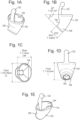
- the ear insert 100 comprises a single piece of moulded silicone or other mouldable and resiliently deformable plastics material.
- the insert comprises a generally rounded outer profile having two integral portions.
- a first tubular portion 102 has a generally oval cross-section and an open first end 104.
- the outer lateral width OW ( Fig. 1C ) of the first tubular portion 102 at the open first end 104 is in the range 7 to 13mm, for example 10 mm for an average adult, and the outer lateral length OL ( Fig. 1C ) is in the range 9.8 to 18mm, for example, 13 mm for an average adult.
- the dimensions of the first tubular portion gradually decrease along its length and at the opposing second end 106, the outer diameter OD1 ( Figure 1F ) may be in the range 6 to 9 mm, for example, 7mm for an average adult.
- An integral second tubular portion 108 extends from the second end 106 of the first tubular portion 102 such that its longitudinal axis is at a 35 -70°, e.g. 45° angle to the longitudinal axis of the first tubular portion 102.
- the outer profile of the insert is convex and relatively gently rounded on one side (the 'rear') to accommodate the angle between the first and second tubular portions 102, 108 and, on the other side (the 'front'), the angle is accommodated by a rounded but relatively sharp concave 'corner' between the first and second tubular portions.
- the second tubular portion 108 which is open at its distal end 109, is of generally circular cross-section and has an outer diameter OD2 ( Fig. 1B ) in the range 5 to 8 mm, for example, 6 mm for an average adult and length L1 ( Figure 2 ) in the range 3.6 to 6.9 mm, for example, 3.6 mm for an average adult. It will be appreciated that the various dimensions can be altered within the ranges given to suit smaller or larger ears, and even child's sizes, as required.
- first and second integral portions 102, 108 together, define a continuous channel 110 therethrough which, itself, is comprised of two portions: the first channel portion 112 being defined through the first tubular portion 102 and the second channel portion 114 being defined through the second tubular portion 108.
- the first channel portion is defined, along the 'front' and 'sides' by the oval-shaped rounded profile of the first tubular portion 102.
- the 'rear' wall of the first tubular portion 102 is thicker than the remaining walls so as to provide a 'rear' channel portion 112 that is substantially flat so as to provide a planar surface 116.
- the planar surface 116 of the first channel portion 113 extends at an acute angle, greater than 45°, toward the second channel portion 114, and the diameter or width of the first channel portion 113 reduces from the open end 104 to the junction with the second channel portion 114 defined by the second tubular portion 108.
- the angle of the planar surface 116, relative to horizontal defined by the lateral plane of the first open end 104 may be in the range 62.5 to 72.5°, for example, 67.5° for an average adult.
- the angled configuration of the second tubular portion 108 relative to the first tubular portion 102 is accommodated at the 'rear' and 'sides' of the insert by a gently rounded outer wall that curves from the first open end 104 to the distal second open end 109 defined by the second tubular portion 108.
- the length L1 ( Figure 2 ) of the second tubular portion 108 is in the range 3.6 mm to 6.9 mm, for example, 3.6 mm for an average adult.
- the diameter ID ( Figure 1F ) of the distal open end 109 may be in the range 2.2 mm to 5 mm, for example, 4 mm for an average adult.
- the open end 109 of the second tubular portion 108 is illustrated as being generally circular in this exemplary embodiment, it may have an alternative shape and configuration. For example, it may be generally oval or 'slit-like' in other exemplary embodiments and the present invention is not necessarily intended to be limited in this regard.
- the thickness of the 'front' and 'side' walls of the second tubular portion 108 are substantially constant along the length to the junction between the first and second tubular portions 102, 108, defined by the concave rounded 'corner' 120.
- the diameter of the second channel portion 114 is substantially constant from the distal open end 109 along a portion of the length of the second tubular portion 108, it tapers inwardly (by means of a thickening of the rear wall of the second tubular portion 108) along a short portion toward the junction between the first and second tubular portions 102, 108, such that that short portion of the inner rear wall of the second channel portion 114 forms an extension of the planar surface 116 defining the 'rear' wall of the first channel portion 113.
- An elongate tab 122 may be provided, extending from the rim of the first tubular portion 102, at its open end 104, to facilitate insertion of the device into, and removal of the device from, a user's ear.
- the ear insert 100 is integrally moulded from a resiliently flexible material such as silicone.
- the insert 100 may have a two-part configuration.
- the device may comprise a metal (e.g. stainless steel or titanium) insert providing defining the first and second channel portions 113, 114 (i.e. the channel including the planar surface 116) and an outer sleeve, formed of a resiliently flexible material such as foam or silicone, defining the curved outer profile to enable the device to be comfortably fitted within a user's ear.
- the reduction in noise distortion when the planar (reflecting) surface 116 is formed of a rigid material can thus be further increased.
- the ear insert 100 is inserted into a user's ear at the open end of the ear canal (adjacent the concha region) such that the second tubular portion extends into the ear canal (with the distal open end 109 facing the tympanic membrane at the other end of the ear canal), and the rounded 'rear' surface of the first tubular portion 102 resting at or just behind the tragus, with the first open end 104 facing backward.
- the outer diameter (OD2) of the second tubular portion 108 is designed, in this example, to be around the same as that of the entrance of the ear canal (external auditory canal) of an average adult.
- the overall length of the insert 100 (excluding the tab 122) is approximately equal to the average length of the external auditory canal of an average adult, wherein the external auditory canal comprises the ear canal extending from the tragus to the middle ear.
- the insert 100 can be fully inserted into the external auditory canal, with the outer edge of the first tubular portion 102 resting against the rear (inner) surface of the tragus and the second tubular portion 108 extending a short way into the ear canal, with the distal open end 109 facing the tympanic membrane.
- the insert 100 is beneficially formed of a soft, resiliently deformable material, such as silicone, so that it can be compressed sufficiently to be inserted into the ear and then released back to its original form, once inserted, to fit snugly within the ear.
- the insert (including the profiled inner channel) is integrally formed of a mouldable material such as silicone.
- the device may comprise an inner member defining the profiled inner channel including the planar surface 116, and an outer sleeve member around the inner member.
- the inner member may be formed of a rigid material such as plastic or metal (e.g. stainless steel or titanium), and the sleeve member could be formed of a resiliently deformable material such as silicone, to provide a comfortable snug fit, in use.
- the angle defined by the longitudinal axis of the second tubular portion 108 is at substantially 45° to the diametric plane defined between the rim around the first open end 104, and the angle of the planar surface 116 provided at the 'rear' inner surface of the first channel portion 113 (and a small portion of the second channel portion 114) is at substantially 22.5° relative to the longitudinal axis of the second tubular portion 108.
- the inventor has discovered that these relative angles, and especially the angle of the planar reflecting surface 116 relative to the first and second open ends 104, 109 of the insert, can provide optimum results in adults with average ear dimensions.
- all dimensions, especially the outer dimensions of the tubular portions 102, 108 can be adjusted (particularly within the tolerances provided) to accommodate, for example, children's' ear dimensions, or adults having larger or smaller external auditory canals.
- the device Once the device is in situ, with the distal open end 109 of the second tubular portion 108 located in the ear canal facing the tympanic membrane, and the 'upper' edge of the first tubular portion 102 resting against the rear (inner) surface of the tragus, with the first open end 104 facing backward, it effectively acts to minimise or even eliminate the effect of the concha on sound waves entering the ear.
- the device still 'funnels' sound waves into the ear canal, due to its tubular shape and configuration, having a first open end 104 of width over double the diameter of the second, distal end 109.
- the angled planar surface 116 acts to minimise the number of times sound waves reaching the external auditory canal are reflected before they reach the tympanic membrane.
- the device acts to reduce distortion in sound waves reaching the tympanic membrane. Without the device, sound waves from a listener's vicinity reach the external auditory canal in the concha region which defines surfaces that can be at up to 90° relative to the longitudinal axis of the ear canal (leading to the tympanic membrane). Thus, sound waves reaching the external auditory canal must change direction by up to 90° to reach the tympanic membrane.
- the ear insert of the present invention acts to 'funnel' more coherent sound waves into the ear canal, with significantly less reflections, thereby reducing distortion (or 'noise') by up to 8% or more. If the user is wearing the insert whilst listening to music, for example through headphones as described above, the quality and clarity of the music heard by the listener is notably improved. Furthermore, and most surprisingly, if a user is wearing the insert(s) whilst conducting their normal day to day lives, the significant reduction in noise distortion provided by the insert(s) acts to reduce instances of triggering, by the Vagus nerve, of the fight-or-flight stress response. Thus, by wearing the insert of the present invention (preferably one in each ear), the user experiences a calming effect, in that stress is reduced during their normal day-to-day lives.
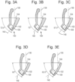
- the effect of the planar (reflecting) surface 116 within the channel is illustrated schematically.
- the incoming sound wave 130 enters the first channel portion 113 at an angle of 72.5° relative to the 'horizontal' defined by the plane of the first open end 104 of the insert 100.
- the incident sound wave 130 hits the reflecting surface 116 within the first tubular portion 102 of the device 100 and the resultant reflected sound wave 140 is directed straight through the second opening 109 toward the tympanic membrane.
- the a single coherent sound wave enters the ear canal.
- incident sound waves 130 at an angle of 70°, 67.5°, 65°, and 62.5° respectively, are reflected by the reflecting surface 116 straight through the second opening 109 in the insert 100 toward the tympanic membrane.
- the ear insert is a stand-alone device for use in improving the quality and clarity of sound heard by a user, who may or may not be wearing headphones.
- an insert of the present invention may be configured to be fitted over each of the integral ear buds of a set of wireless headphones, or as a tip for any existing ear phones with tube output.
- an insert according to the invention may be configured to be fitted with resiliency deformable tip, such as that used in conventional earplugs and in-ear headphones.
Landscapes
- Health & Medical Sciences (AREA)
- Engineering & Computer Science (AREA)
- Physics & Mathematics (AREA)
- Acoustics & Sound (AREA)
- Life Sciences & Earth Sciences (AREA)
- General Health & Medical Sciences (AREA)
- Otolaryngology (AREA)
- Signal Processing (AREA)
- Biophysics (AREA)
- Psychology (AREA)
- Biomedical Technology (AREA)
- Heart & Thoracic Surgery (AREA)
- Vascular Medicine (AREA)
- Animal Behavior & Ethology (AREA)
- Public Health (AREA)
- Veterinary Medicine (AREA)
- Neurosurgery (AREA)
- Manufacturing & Machinery (AREA)
- Headphones And Earphones (AREA)
- Prostheses (AREA)
Claims (9)
- Ohreinsatz (100), der eine im Allgemeinen trichterförmige Wand aufweist, die einen sich verjüngenden Kanal definiert, der sich zwischen einem ersten und einem zweiten offenen Ende (104, 109) erstreckt, wobei das erste offene Ende (104) einen Durchmesser oder eine Breite aufweist, der/die größer ist als der/diejenige des zweiten offenen Endes, wobei ein Abschnitt der trichterförmigen Wand, der unmittelbar an das zweite offene Ende (109) angrenzt, so konfiguriert ist, dass der Ohreinsatz zur Verwendung innerhalb der Öffnung des Gehörgangs eines Benutzers angeordnet werden kann, wobei das erste offene Ende (104) an den Tragus des Benutzers angrenzt und das zweite offene Ende (109) dem Trommelfell des Benutzers zugewandt ist, wobei mindestens ein Abschnitt des sich verjüngenden Kanals eine akustische Wellen reflektierende Region (116) umfasst, die sich von einem Ort an oder in der Nähe des ersten offenen Endes (104) in Richtung des zweiten offenen Endes (109) in einem Winkel zwischen 60° und 75° relativ zu einer seitlichen Ebene erstreckt, die durch den Rand der trichterförmigen Wand am ersten offenen Ende definiert ist; dadurch gekennzeichnet, dass die akustische Wellen reflektierende Region (116) eine im Wesentlichen ebene Oberfläche umfasst.
- Ohreinsatz (100) nach Anspruch 1, wobei sich die akustische Wellen reflektierende Region (116) von einem Ort am oder in der Nähe des ersten offenen Endes (104) in Richtung des zweiten offenen Endes (109) in einem Winkel zwischen 65° und 70° relativ zu der durch den Rand der trichterförmigen Wand am ersten offenen Ende (104) definierten seitlichen Ebene erstreckt.
- Ohreinsatz (100) nach einem der vorstehenden Ansprüche, der so konfiguriert ist, dass er auf oder über eine Ohrmuschel eines In-Ear-Kopfhörers passt.
- Ohreinsatz (100) nach einem der Ansprüche 1 bis 3, der am zweiten offenen Ende so geformt und konfiguriert ist, dass er eine elastische Spitze empfängt und festhält.
- Ohreinsatz (100) nach einem der vorstehenden Ansprüche, wobei ein Abschnitt der trichterförmigen Wand unmittelbar neben dem zweiten offenen Ende (109) einen im Allgemeinen rohrförmigen Abschnitt (108) mit einer Längsachse aufweist, die sich in einem Winkel relativ zu der durch den Rand der trichterförmigen Wand am ersten offenen Ende (104) definierten seitlichen Ebene erstreckt, wobei sich das zweite offene Ende (109) am distalen Ende des rohrförmigen Abschnitts (108) befindet.
- Ohreinsatz (100) nach Anspruch 5, wobei der röhrenförmige Abschnitt (108) so konfiguriert ist, dass er zum Gebrauch in einen Gehörgang eingeführt wird, wobei das zweite offene Ende (109) dem Trommelfell des Benutzers zugewandt ist und das erste offene Ende im Allgemeinen nach hinten zum Benutzer weist.
- Ohreinsatz (100) nach Anspruch 5 oder 6, wobei das Außenprofil der trichterförmigen Wand eine abgerundete konvexe Region umfasst, die sich von einem Rand in der Nähe des ersten offenen Endes zu einem Rand in der Nähe des zweiten offenen Endes (109) erstreckt, und eine gegenüberliegende konkave Region am proximalen Ende des rohrförmigen Abschnitts (108) zwischen dem ersten und dem zweiten offenen Ende (104, 109).
- Ohreinsatz (100) nach Anspruch 7, wobei die konkave Region eine Vorderseite des Ohreinsatzes definiert und die diametral gegenüberliegende konvexe Oberfläche die Rückseite des Einsatzes definiert, wenn dieser in Gebrauch ist, und wobei die Gesamtlänge der trichterförmigen Wand so konfiguriert ist, dass bei Gebrauch, wenn der röhrenförmige Abschnitt (108) teilweise in den Gehörgang eines Benutzers eingeführt ist, der Rand des ersten offenen Endes (104) an der Rückseite des Ohreinsatzes neben der Innenoberfläche des Tragus des Benutzers liegt.
- Ohreinsatz (100) nach einem der Ansprüche 5 bis 8, wobei das zweite offene Ende (109) im Allgemeinen elliptisch ist.
Applications Claiming Priority (2)
| Application Number | Priority Date | Filing Date | Title |
|---|---|---|---|
| GB2004011.9A GB2593205A (en) | 2020-03-19 | 2020-03-19 | An ear insert |
| PCT/GB2021/050676 WO2021186182A1 (en) | 2020-03-19 | 2021-03-18 | An ear insert |
Publications (3)
| Publication Number | Publication Date |
|---|---|
| EP4120979A1 EP4120979A1 (de) | 2023-01-25 |
| EP4120979B1 true EP4120979B1 (de) | 2025-05-07 |
| EP4120979C0 EP4120979C0 (de) | 2025-05-07 |
Family
ID=70546736
Family Applications (1)
| Application Number | Title | Priority Date | Filing Date |
|---|---|---|---|
| EP21714356.9A Active EP4120979B1 (de) | 2020-03-19 | 2021-03-18 | Ohreinsatz |
Country Status (7)
| Country | Link |
|---|---|
| US (1) | US12137313B2 (de) |
| EP (1) | EP4120979B1 (de) |
| CN (1) | CN115243652B (de) |
| AU (1) | AU2021238937B2 (de) |
| CA (1) | CA3169269A1 (de) |
| GB (1) | GB2593205A (de) |
| WO (1) | WO2021186182A1 (de) |
Families Citing this family (5)
| Publication number | Priority date | Publication date | Assignee | Title |
|---|---|---|---|---|
| USD1058539S1 (en) * | 2020-03-23 | 2025-01-21 | Flare Audio Technologies Limited | Earphone |
| US20220313423A1 (en) * | 2021-04-02 | 2022-10-06 | United States Government As Represented By The Department Of Veterans Affairs | Ear Stent And Methods Of Using Same |
| GB2614033A (en) * | 2021-10-14 | 2023-06-28 | Flare Audio Tech Limited | Ear insert |
| WO2025093849A1 (en) | 2023-11-03 | 2025-05-08 | Flare Audio Technologies Limited | Ear insert |
| WO2025093847A1 (en) | 2023-11-03 | 2025-05-08 | Flare Audio Technologies Limited | Ear insert |
Family Cites Families (10)
| Publication number | Priority date | Publication date | Assignee | Title |
|---|---|---|---|---|
| GB190116423A (en) * | 1901-08-15 | 1902-01-16 | Samuel Giles Payn | Improvements in Magnetic Devices to Restore and Aid the Hearing. |
| US8189845B2 (en) * | 2006-12-21 | 2012-05-29 | Sperian Hearing Protection, Llc | Earbud coupling |
| US9532127B2 (en) * | 2008-01-07 | 2016-12-27 | Burton Technologies, Llc | Earbuds and in-ear adapter for earbuds |
| US8061472B2 (en) * | 2009-06-03 | 2011-11-22 | Sperian Hearing Protection, Llc | Non-roll foam eartip |
| JP2013135266A (ja) * | 2011-12-26 | 2013-07-08 | D & M Holdings Inc | ヘッドホン装置 |
| JP5894322B1 (ja) * | 2015-09-08 | 2016-03-30 | 盛崇 小倉 | 簡易型補聴器具 |
| CN205336492U (zh) * | 2016-01-21 | 2016-06-22 | 唐永均 | 一种头戴式耳机 |
| AU2017365735A1 (en) * | 2016-11-28 | 2019-07-11 | Innovere Medical Inc. | Systems, methods and devices for communication in noisy environments |
| CN208598633U (zh) * | 2017-08-08 | 2019-03-15 | 珠海卓力声科技有限公司 | 弯头降噪耳塞 |
| KR200492228Y1 (ko) * | 2018-06-05 | 2020-09-01 | 탐라엔씨(주) | 양방향 소음차단 귀마개 |
-
2020
- 2020-03-19 GB GB2004011.9A patent/GB2593205A/en not_active Withdrawn
-
2021
- 2021-03-18 WO PCT/GB2021/050676 patent/WO2021186182A1/en not_active Ceased
- 2021-03-18 AU AU2021238937A patent/AU2021238937B2/en active Active
- 2021-03-18 EP EP21714356.9A patent/EP4120979B1/de active Active
- 2021-03-18 CN CN202180022230.6A patent/CN115243652B/zh active Active
- 2021-03-18 CA CA3169269A patent/CA3169269A1/en active Pending
-
2022
- 2022-08-31 US US17/899,674 patent/US12137313B2/en active Active
Also Published As
| Publication number | Publication date |
|---|---|
| CA3169269A1 (en) | 2021-09-23 |
| GB202004011D0 (en) | 2020-05-06 |
| US20220417638A1 (en) | 2022-12-29 |
| EP4120979A1 (de) | 2023-01-25 |
| AU2021238937A1 (en) | 2022-09-22 |
| CN115243652A (zh) | 2022-10-25 |
| GB2593205A (en) | 2021-09-22 |
| WO2021186182A1 (en) | 2021-09-23 |
| EP4120979C0 (de) | 2025-05-07 |
| AU2021238937B2 (en) | 2026-02-19 |
| US12137313B2 (en) | 2024-11-05 |
| CN115243652B (zh) | 2026-03-20 |
Similar Documents
| Publication | Publication Date | Title |
|---|---|---|
| EP4120979B1 (de) | Ohreinsatz | |
| US20220183892A1 (en) | Device for protecting the human sensory hearing system while retaining quality sound | |
| EP2749043B2 (de) | Ohrpassstück zur schalldämpfung | |
| JP4839016B2 (ja) | 補聴器用柔軟性耳当て | |
| CN107548561B (zh) | 耳机 | |
| AU2019214441B2 (en) | Universal adapter for hearing aids and earphones | |
| CN101218851A (zh) | 助听器和用于助听器的耳机 | |
| JP2008532445A (ja) | 補聴器用イヤープラグ | |
| CA2579358C (en) | Earpiece for a hearing aid and a hearing aid | |
| US20240251201A1 (en) | Ear insert | |
| CN105122842A (zh) | 耳背式助听器 | |
| GB2635220A (en) | Ear insert | |
| GB2635215A (en) | Ear insert | |
| US20180103310A1 (en) | Light weight headphone | |
| KR20050112325A (ko) | 이어폰의 귀삽입구 | |
| WO2025093849A1 (en) | Ear insert | |
| GB2639521A (en) | Ear insert | |
| WO2025093847A1 (en) | Ear insert | |
| CN118843029A (zh) | 耳塞头 | |
| KR200253166Y1 (ko) | 휴대용 이어폰 | |
| WO2025104414A1 (en) | Device for improving sound quality | |
| JPH05284584A (ja) | イヤーマイク |
Legal Events
| Date | Code | Title | Description |
|---|---|---|---|
| STAA | Information on the status of an ep patent application or granted ep patent |
Free format text: STATUS: UNKNOWN |
|
| STAA | Information on the status of an ep patent application or granted ep patent |
Free format text: STATUS: THE INTERNATIONAL PUBLICATION HAS BEEN MADE |
|
| PUAI | Public reference made under article 153(3) epc to a published international application that has entered the european phase |
Free format text: ORIGINAL CODE: 0009012 |
|
| STAA | Information on the status of an ep patent application or granted ep patent |
Free format text: STATUS: REQUEST FOR EXAMINATION WAS MADE |
|
| 17P | Request for examination filed |
Effective date: 20220825 |
|
| AK | Designated contracting states |
Kind code of ref document: A1 Designated state(s): AL AT BE BG CH CY CZ DE DK EE ES FI FR GB GR HR HU IE IS IT LI LT LU LV MC MK MT NL NO PL PT RO RS SE SI SK SM TR |
|
| DAV | Request for validation of the european patent (deleted) | ||
| DAX | Request for extension of the european patent (deleted) | ||
| REG | Reference to a national code |
Ref country code: DE Ref legal event code: R079 Free format text: PREVIOUS MAIN CLASS: A61F0011000000 Ipc: A61F0011300000 Ref country code: DE Ref legal event code: R079 Ref document number: 602021030405 Country of ref document: DE Free format text: PREVIOUS MAIN CLASS: A61F0011000000 Ipc: A61F0011300000 |
|
| GRAP | Despatch of communication of intention to grant a patent |
Free format text: ORIGINAL CODE: EPIDOSNIGR1 |
|
| STAA | Information on the status of an ep patent application or granted ep patent |
Free format text: STATUS: GRANT OF PATENT IS INTENDED |
|
| RIC1 | Information provided on ipc code assigned before grant |
Ipc: H04R 1/10 20060101ALI20241107BHEP Ipc: A61F 11/30 20220101AFI20241107BHEP |
|
| INTG | Intention to grant announced |
Effective date: 20241127 |
|
| GRAS | Grant fee paid |
Free format text: ORIGINAL CODE: EPIDOSNIGR3 |
|
| GRAA | (expected) grant |
Free format text: ORIGINAL CODE: 0009210 |
|
| STAA | Information on the status of an ep patent application or granted ep patent |
Free format text: STATUS: THE PATENT HAS BEEN GRANTED |
|
| AK | Designated contracting states |
Kind code of ref document: B1 Designated state(s): AL AT BE BG CH CY CZ DE DK EE ES FI FR GB GR HR HU IE IS IT LI LT LU LV MC MK MT NL NO PL PT RO RS SE SI SK SM TR |
|
| REG | Reference to a national code |
Ref country code: GB Ref legal event code: FG4D |
|
| REG | Reference to a national code |
Ref country code: CH Ref legal event code: EP |
|
| REG | Reference to a national code |
Ref country code: DE Ref legal event code: R096 Ref document number: 602021030405 Country of ref document: DE |
|
| REG | Reference to a national code |
Ref country code: IE Ref legal event code: FG4D |
|
| U01 | Request for unitary effect filed |
Effective date: 20250603 |
|
| U07 | Unitary effect registered |
Designated state(s): AT BE BG DE DK EE FI FR IT LT LU LV MT NL PT RO SE SI Effective date: 20250611 |
|
| PG25 | Lapsed in a contracting state [announced via postgrant information from national office to epo] |
Ref country code: ES Free format text: LAPSE BECAUSE OF FAILURE TO SUBMIT A TRANSLATION OF THE DESCRIPTION OR TO PAY THE FEE WITHIN THE PRESCRIBED TIME-LIMIT Effective date: 20250507 |
|
| PG25 | Lapsed in a contracting state [announced via postgrant information from national office to epo] |
Ref country code: NO Free format text: LAPSE BECAUSE OF FAILURE TO SUBMIT A TRANSLATION OF THE DESCRIPTION OR TO PAY THE FEE WITHIN THE PRESCRIBED TIME-LIMIT Effective date: 20250807 Ref country code: GR Free format text: LAPSE BECAUSE OF FAILURE TO SUBMIT A TRANSLATION OF THE DESCRIPTION OR TO PAY THE FEE WITHIN THE PRESCRIBED TIME-LIMIT Effective date: 20250808 |
|
| PG25 | Lapsed in a contracting state [announced via postgrant information from national office to epo] |
Ref country code: PL Free format text: LAPSE BECAUSE OF FAILURE TO SUBMIT A TRANSLATION OF THE DESCRIPTION OR TO PAY THE FEE WITHIN THE PRESCRIBED TIME-LIMIT Effective date: 20250507 |
|
| PG25 | Lapsed in a contracting state [announced via postgrant information from national office to epo] |
Ref country code: HR Free format text: LAPSE BECAUSE OF FAILURE TO SUBMIT A TRANSLATION OF THE DESCRIPTION OR TO PAY THE FEE WITHIN THE PRESCRIBED TIME-LIMIT Effective date: 20250507 |
|
| PG25 | Lapsed in a contracting state [announced via postgrant information from national office to epo] |
Ref country code: RS Free format text: LAPSE BECAUSE OF FAILURE TO SUBMIT A TRANSLATION OF THE DESCRIPTION OR TO PAY THE FEE WITHIN THE PRESCRIBED TIME-LIMIT Effective date: 20250807 |
|
| PG25 | Lapsed in a contracting state [announced via postgrant information from national office to epo] |
Ref country code: IS Free format text: LAPSE BECAUSE OF FAILURE TO SUBMIT A TRANSLATION OF THE DESCRIPTION OR TO PAY THE FEE WITHIN THE PRESCRIBED TIME-LIMIT Effective date: 20250907 |
|
| PG25 | Lapsed in a contracting state [announced via postgrant information from national office to epo] |
Ref country code: SM Free format text: LAPSE BECAUSE OF FAILURE TO SUBMIT A TRANSLATION OF THE DESCRIPTION OR TO PAY THE FEE WITHIN THE PRESCRIBED TIME-LIMIT Effective date: 20250507 |
|
| PG25 | Lapsed in a contracting state [announced via postgrant information from national office to epo] |
Ref country code: CZ Free format text: LAPSE BECAUSE OF FAILURE TO SUBMIT A TRANSLATION OF THE DESCRIPTION OR TO PAY THE FEE WITHIN THE PRESCRIBED TIME-LIMIT Effective date: 20250507 |
|
| PG25 | Lapsed in a contracting state [announced via postgrant information from national office to epo] |
Ref country code: SK Free format text: LAPSE BECAUSE OF FAILURE TO SUBMIT A TRANSLATION OF THE DESCRIPTION OR TO PAY THE FEE WITHIN THE PRESCRIBED TIME-LIMIT Effective date: 20250507 |
|
| PLBE | No opposition filed within time limit |
Free format text: ORIGINAL CODE: 0009261 |
|
| STAA | Information on the status of an ep patent application or granted ep patent |
Free format text: STATUS: NO OPPOSITION FILED WITHIN TIME LIMIT |
|
| REG | Reference to a national code |
Ref country code: CH Ref legal event code: L10 Free format text: ST27 STATUS EVENT CODE: U-0-0-L10-L00 (AS PROVIDED BY THE NATIONAL OFFICE) Effective date: 20260318 |
|
| PGFP | Annual fee paid to national office [announced via postgrant information from national office to epo] |
Ref country code: GB Payment date: 20260326 Year of fee payment: 6 |
|
| 26N | No opposition filed |
Effective date: 20260210 |