EP4120930B1 - Geführte fräsvorrichtung für prothetische chirurgie - Google Patents
Geführte fräsvorrichtung für prothetische chirurgie Download PDFInfo
- Publication number
- EP4120930B1 EP4120930B1 EP21718242.7A EP21718242A EP4120930B1 EP 4120930 B1 EP4120930 B1 EP 4120930B1 EP 21718242 A EP21718242 A EP 21718242A EP 4120930 B1 EP4120930 B1 EP 4120930B1
- Authority
- EP
- European Patent Office
- Prior art keywords
- milling
- milling tool
- longitudinal axis
- rotating rod
- respect
- Prior art date
- Legal status (The legal status is an assumption and is not a legal conclusion. Google has not performed a legal analysis and makes no representation as to the accuracy of the status listed.)
- Active
Links
Images







Classifications
-
- A—HUMAN NECESSITIES
- A61—MEDICAL OR VETERINARY SCIENCE; HYGIENE
- A61B—DIAGNOSIS; SURGERY; IDENTIFICATION
- A61B17/00—Surgical instruments, devices or methods
- A61B17/16—Instruments for performing osteoclasis; Drills or chisels for bones; Trepans
- A61B17/1613—Component parts
- A61B17/162—Chucks or tool parts which are to be held in a chuck
-
- A—HUMAN NECESSITIES
- A61—MEDICAL OR VETERINARY SCIENCE; HYGIENE
- A61B—DIAGNOSIS; SURGERY; IDENTIFICATION
- A61B17/00—Surgical instruments, devices or methods
- A61B17/16—Instruments for performing osteoclasis; Drills or chisels for bones; Trepans
- A61B17/1613—Component parts
- A61B17/1622—Drill handpieces
- A61B17/1624—Drive mechanisms therefor
-
- A—HUMAN NECESSITIES
- A61—MEDICAL OR VETERINARY SCIENCE; HYGIENE
- A61B—DIAGNOSIS; SURGERY; IDENTIFICATION
- A61B17/00—Surgical instruments, devices or methods
- A61B17/16—Instruments for performing osteoclasis; Drills or chisels for bones; Trepans
- A61B17/1613—Component parts
- A61B17/1633—Sleeves, i.e. non-rotating parts surrounding the bit shaft, e.g. the sleeve forming a single unit with the bit shaft
-
- A—HUMAN NECESSITIES
- A61—MEDICAL OR VETERINARY SCIENCE; HYGIENE
- A61B—DIAGNOSIS; SURGERY; IDENTIFICATION
- A61B17/00—Surgical instruments, devices or methods
- A61B17/16—Instruments for performing osteoclasis; Drills or chisels for bones; Trepans
- A61B17/164—Instruments for performing osteoclasis; Drills or chisels for bones; Trepans intramedullary
-
- A—HUMAN NECESSITIES
- A61—MEDICAL OR VETERINARY SCIENCE; HYGIENE
- A61B—DIAGNOSIS; SURGERY; IDENTIFICATION
- A61B17/00—Surgical instruments, devices or methods
- A61B17/16—Instruments for performing osteoclasis; Drills or chisels for bones; Trepans
- A61B17/1659—Surgical rasps, files, planes, or scrapers
-
- A—HUMAN NECESSITIES
- A61—MEDICAL OR VETERINARY SCIENCE; HYGIENE
- A61B—DIAGNOSIS; SURGERY; IDENTIFICATION
- A61B17/00—Surgical instruments, devices or methods
- A61B17/16—Instruments for performing osteoclasis; Drills or chisels for bones; Trepans
- A61B17/1613—Component parts
- A61B17/1615—Drill bits, i.e. rotating tools extending from a handpiece to contact the worked material
- A61B17/1617—Drill bits, i.e. rotating tools extending from a handpiece to contact the worked material with mobile or detachable parts
-
- A—HUMAN NECESSITIES
- A61—MEDICAL OR VETERINARY SCIENCE; HYGIENE
- A61B—DIAGNOSIS; SURGERY; IDENTIFICATION
- A61B17/00—Surgical instruments, devices or methods
- A61B17/16—Instruments for performing osteoclasis; Drills or chisels for bones; Trepans
- A61B17/1613—Component parts
- A61B17/1631—Special drive shafts, e.g. flexible shafts
-
- A—HUMAN NECESSITIES
- A61—MEDICAL OR VETERINARY SCIENCE; HYGIENE
- A61B—DIAGNOSIS; SURGERY; IDENTIFICATION
- A61B17/00—Surgical instruments, devices or methods
- A61B17/16—Instruments for performing osteoclasis; Drills or chisels for bones; Trepans
- A61B17/1662—Instruments for performing osteoclasis; Drills or chisels for bones; Trepans for particular parts of the body
- A61B17/1675—Instruments for performing osteoclasis; Drills or chisels for bones; Trepans for particular parts of the body for the knee
-
- A—HUMAN NECESSITIES
- A61—MEDICAL OR VETERINARY SCIENCE; HYGIENE
- A61B—DIAGNOSIS; SURGERY; IDENTIFICATION
- A61B17/00—Surgical instruments, devices or methods
- A61B17/16—Instruments for performing osteoclasis; Drills or chisels for bones; Trepans
- A61B17/1662—Instruments for performing osteoclasis; Drills or chisels for bones; Trepans for particular parts of the body
- A61B17/1684—Instruments for performing osteoclasis; Drills or chisels for bones; Trepans for particular parts of the body for the shoulder
-
- A—HUMAN NECESSITIES
- A61—MEDICAL OR VETERINARY SCIENCE; HYGIENE
- A61B—DIAGNOSIS; SURGERY; IDENTIFICATION
- A61B17/00—Surgical instruments, devices or methods
- A61B17/16—Instruments for performing osteoclasis; Drills or chisels for bones; Trepans
- A61B17/1697—Instruments for performing osteoclasis; Drills or chisels for bones; Trepans specially adapted for wire insertion
-
- A—HUMAN NECESSITIES
- A61—MEDICAL OR VETERINARY SCIENCE; HYGIENE
- A61B—DIAGNOSIS; SURGERY; IDENTIFICATION
- A61B17/00—Surgical instruments, devices or methods
- A61B17/16—Instruments for performing osteoclasis; Drills or chisels for bones; Trepans
- A61B2017/1602—Mills
Definitions
- the present invention concerns a guided milling device for prosthetic surgery suitable for the preparation of seatings for bone fillers or for the preparation of housing seatings in the bone for a prosthesis.
- congenital or traumatic degenerative diseases for example primary arthrosis or secondary arthrosis, due to trauma or caused by infections, rheumatoid arthritis, inflammatory arthritis, osteonecrosis, or bone tumors, or other similar problems, require implantation of a prosthesis able to reproduce, overall, a movement similar to that of the healthy joint.
- the knee prosthesis typically comprises a femoral component, which is attached to the distal end of the femur, and a tibial component, which is attached to the proximal end of the tibia.
- the creation of a bone seating for the application of suitable support cones, first requires that a hole is made, with one or more boring devices of increasing diameter, and subsequently that the hole is shaped with a suitable milling device.
- milling devices are known, which can be used during prosthetic surgery for the preparation of said seatings.
- milling devices typically comprise a handling body provided with a rotating rod which develops along a longitudinal axis, substantially coinciding with the axis of the intra-medullary canal, depending on the case, of the tibia or femur, and provided with a proximal end which has a connector to a drive member and a distal end connected to a milling tool, made to rotate by the drive member.
- One of the disadvantages of known milling devices is that they are configured to shape the bone seating in the direction of a milling axis which substantially coincides with the axis of the intra-medullary canal, and consequently with the longitudinal axis around which the rotating rod is driven, depending on the case, of the tibia or femur; such devices are therefore not able to follow the specific anatomy of the tibial and femoral bone.
- the milling device often comprises, or is combined with, a guide rod which is previously inserted into the intra-medullary canal.
- the guide rod is slidably positioned inside the milling device along the longitudinal axis, and therefore is also coaxial to the milling axis.
- the surgeon is therefore obliged to make bone seatings of a limited size which may, however, not be sufficient to guarantee adequate joint stability of the prosthesis, especially in the case where previous prostheses implants have damaged or otherwise rendered unusable an extended zone of the spongy part of the bone, or the removal of the previous implant has created significant bone loss or there is degeneration or lack of bone.
- one purpose of the present invention is to provide a guided milling device for prosthetic surgery which is able to perform milling operations while avoiding damage to the cortical zone of the bone.
- Another purpose of the present invention is to provide a guided milling device for prosthetic surgery which is able to obtain a stable milling with respect to a milling axis different from the axis of the intra-medullary canal or different from the axis of the guide rod that is inserted into it.
- Another purpose of the present invention is to provide a guided milling device for prosthetic surgery which is simple to use and which consists of a limited number of components.
- Another purpose of the present invention is to provide a guided milling device for prosthetic surgery which is simple to assemble, in order to carry out the surgical operation, and to disassemble, in order to carry out cleaning and sterilization thereof.
- the guided milling device for prosthetic surgery comprises a milling tool rotating about a milling axis, and a handling body having a drive rotating rod which develops along a longitudinal axis of linear rotation.
- the rotating rod is connected to the milling tool in order to make the milling tool rotate about the milling axis.
- the rotating rod is internally hollow and has a guide channel parallel to the longitudinal axis and in which a guide rod is positioned coaxially in a slidable manner, able to be positioned so as to extend beyond the milling tool along the longitudinal axis.
- the milling axis is inclined with respect to the longitudinal axis, so that the milling tool is disposed inclined with respect to the rotating rod and also with respect to the guide rod.
- Embodiments described using the attached drawings concern a guided milling device for prosthetic surgery, indicated as a whole with reference number 10 in the attached drawings.
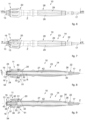
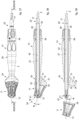
- figs. 1-9 , 37-42 concern a guided milling device 10 suitable for making seatings for bone fillers for the tibial bone
- figs. 10-13 , 43-46 concern a milling device 10 suitable for making seatings for bone fillers for the femoral bone
- figs. 14-17 concern a milling device 10 suitable for making seatings for a shoulder joint prosthesis, also called humeral prosthesis.
- Figs. 18-20 show embodiments of the milling device 10 respectively configured for the preparation of a seating in the tibial bone, in the femoral bone and in the shoulder joint, in which a guide rod 50 is slidingly associated.
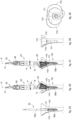
- FIGS. 21-24 concern another embodiment of the milling device 10 suitable for making seatings for a shoulder joint prosthesis, in particular for the glenoid, figs. 25-29 and 30-33 concern the use for milling of the tibial and femoral bone respectively.
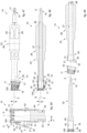
- Other embodiments shown in figs. 47-50 concern a milling device 10 suitable for making seatings for the hip joint.
- the guide rod 50 which is coupled, during use, with the device 10 is the coupling cone of a hip prosthesis rod already previously implanted in the femoral canal.
- the guided milling device for prosthetic surgery 10, hereafter device 10, comprises a milling tool 11, rotating about a milling axis R, and a handling body 14 having a drive rotating rod 22 which develops along a longitudinal axis Z of linear rotation.
- the rotating rod 22 is connected to the milling tool 11 to make the milling tool 11 rotate about the milling axis R.
- This longitudinal axis Z is favorably a linear axis.
- the rotating rod 22 is cannulated, that is, it is internally hollow and has a guide channel 42 parallel to the longitudinal axis Z and suitable to house a guide or reference rod 50 necessary to axially position the device 10 in the desired milling position during the surgical operation.
- the guide rod 50 is coaxially housed in the guide channel 42 and is slidably positioned therein to extend beyond the milling tool 11 along the longitudinal axis Z.
- the amount by which the guide rod 50 extends beyond the milling tool 11 is coordinated and aimed at the insertion of the guide rod 50 into the intra-medullary canal, in order to guide the milling operation (see for example figs. 21-23 , 25-27 , 30-32 , 34-36 ).
- the guide rod 50 can also be the coupling cone of a hip prosthesis rod previously implanted in the femoral canal ( figs. 47-50 ).
- the milling axis R is inclined with respect to the longitudinal axis Z, so that the milling tool 11 is disposed inclined with respect to the rotating rod 22 and also with respect to the guide rod 50.
- the guide rod 50 has, at least in the proximal part, a transverse size, in particular a diameter, which is smaller than the transverse size of the guide channel 42, so that it can be inserted in the latter, but with limited transverse play.
- the guide rod 50 can have a diameter which is also larger, which is a function of the anatomical canal.
- the guide rod 50 or at least a guide portion 50a thereof, can have a shorter length than the length of the guide channel 42 measured along the longitudinal axis Z.
- the milling tool 11 although it is guided along the guide rod 50 and therefore along the longitudinal axis Z, allows to define a bone seating having a development along an axis that is different to that of the guide rod 50, that is, along the milling axis R inclined with respect to the longitudinal axis Z.
- the guide rod 50 can be a reference pin, a more or less thin rigid shaft, a so-called Kirschner wire or "lead wire", for example in the case of a shoulder joint, or similar guide element.
- the guide rod 50 can have a shaped tip, with teeth, coils or other elements, to act as a reamer mean, for example in the event it is used for the tibial or femoral intra-medullary canal.
- the guide rod 50 can generally be a reaming device which, suitably driven by a motorized or manual drive mean, is used before the device 10 in order to create a first hole, or first holes of increasing diameters in the intra-medullary canal.
- the guide rod 50 is left in the intra-medullary canal where the hole was created and is released from the drive mean.
- the device 10 is prepared so that the guide rod 50 is inserted into the guide channel 42 and acts as an axial guide during the milling operation.
- the guide rod 50 comprises a guide portion 50a able to cooperate with the guide channel 42, and a reaming portion 50b which always remains outside the milling tool 11.
- the guide rod 50 is configured as a guide wire, also called Kirschner wire or k-wire, or it can also be a so-called "lead wire".
- the intra-medullary canal has a reduced cross-section compared to the tibial or femoral bone and it is not possible to use a reaming tool as in the applications to the femoral and tibial bones.
- the milling tool 11 is guided and advances along the wire, which in this case acts as a guide rod 50, previously inserted and aligned along the final axis of the prosthetic implant.
- the milling tool 11 is able to rotate and prepare a seating, for example of a spherical shape, oriented along an axis - the milling axis R - that is inclined with respect to that of the wire which acts as a guide rod 50 - coinciding with the longitudinal axis Z.
- the inclined axis along which the seating being prepared is oriented is an axis essentially orthogonal to the eroded surface of the glenoid.
- the handling body 14 comprises an angular positioning assembly 51 configured to define the inclined disposition of the milling tool 11 with respect to the guide rod 50 and to the rotating rod 22, as described above.
- the angular positioning assembly 51 comprises articulation means 54, to connect the milling tool 11 to the rotating rod 22 in an articulated manner, and a positioning member 20, disposed on a tubular handle 23 of the handling body 14.
- the articulation means 54 can comprise an angular joint 18 (see for example figs. 1 , 10 and 14 ), disposed on one end of the rotating rod 22, or, or in addition, a pair of articulated surfaces 52, 53 (see for example figs. 23-24 ) respectively defined on the rotating rod 22 and on an internal part of the milling tool 11, so as to configure a spherical joint.
- the angular joint 18 lies on the longitudinal axis Z.
- the angular joint 18 essentially lies on the intersection of the longitudinal axis Z and the milling axis R.
- the angular joint 18 can be completely contained inside the milling tool 11, see for example figs. 8-9 , or be partly outside and partly inside the milling tool 11, see for example fig. 23 and fig. 50 .
- the articulation means 54 allow to selectively define a plurality of inclined positions of the milling tool 11 with respect to the longitudinal axis Z.
- the positioning member 20 comprises a stabilizing body 21 disposed eccentric with respect to the longitudinal axis Z and configured to cooperate with the milling tool 11 so as to selectively define, from among the plurality of inclined positions as above, a single specific stable inclined position of the milling tool 11 with respect to the longitudinal axis Z.
- the specific stable inclined position allows the milling tool 11 to rotate with respect to the milling axis R.
- the milling axis R is inclined with respect to the longitudinal axis Z of rotation of the rotating rod 22 by an angle of inclination ⁇ which varies according to the surgical application (application to the tibial bone, to the femoral bone or to the shoulder joint). Therefore it can be said that the milling tool 11 is inclined with respect to the rotating rod 22 and with respect to the guide rod 50.
- the positioning member 20 defines the angle of inclination ⁇ so that when the rotating rod 22 rotates with respect to the longitudinal axis Z, the milling tool 11 rotates with respect to the milling axis R.
- the device 10 As shown schematically in fig. 5 , with this configuration of the device 10 it is possible to create a bone seating without damaging the cortical zone 110 of the bone.
- this device 10 shapes the bone seating as above with respect to the angle of inclination ⁇ that corresponds to the specific stable inclined position.
- the milling tool 11 can have the profile of a solid of revolution, obtained rotating a desired curve, which for example approximates the internal geometry of the tibia or femur.
- a known milling device is schematically shown in a dashed line, the device 10 in accordance with the embodiments described here is shown in a continuous line.
- the known milling device comes much closer to the cortical zone 110, with the risk of damaging it by perforating it.
- this allows the user to create a deeper bone seating, being able to ensure, especially in the case of severe degeneration of the spongy part of the bone, a suitable joint stability of the prosthesis.
- the milling tool 11 has a concave coupling seating 12 having a polar coupling aperture 13, through which the guide rod 50 is made through.
- the guide rod 50 therefore, has a smaller transverse size than the transverse size of the polar coupling aperture 13.
- the rotating rod 22 is provided with a distal end 16 connected to the milling tool 11 inside the concave coupling seating 12 in correspondence with the polar coupling aperture 13, and a proximal end 15 which has a tang 17 for attachment to a drive member to make the milling tool 11 rotate about the milling axis R.
- the distal end 16 is open to allow the guide rod 50 access to the guide channel 42.
- proximal and distal when they describe the rotating rod 22 of the milling device 10 are defined with reference to the perspective of the milling device 10.
- proximal refers to the direction of coupling with the attachment tang 17
- distal refers to the direction of coupling with the milling tool 11. Consequently, the relative terms “proximal” and “distal” when applied to other components refer to the reference described above.
- the rotating rod 22 can be provided, in the head or distal position, with a front milling tip 55 which is outside the milling tool 11 and cooperating with the latter to create a seating for the prosthetic implant.
- the front milling tip 55 can be made in a single piece with the rotating rod 22, in correspondence with its distal end 16, and is therefore integral in rotation with the rotating rod 22.
- the front milling tip 55 has an axial aperture to allow the passage of the guide rod 50 in the guide channel 42.
- the front milling tip 55 also rotates, thus also making an axial hole in the bone (along the longitudinal axis Z) which houses the part of the rotating rod 22 axially protruding from the milling tool 11.
- the front milling tip 55 therefore, rotates about an axis coaxial to the longitudinal axis Z, and not about the milling axis R of the milling tool 11.
- the point of intersection of the milling axis R and the longitudinal axis Z falls outside the milling tool 11 (see in particular fig. 23 ).
- the embodiment shown in figs. 47-50 also shows a device 10 provided with a front milling head 155.
- the device 10 is suitable for surgical applications of the hip joint.
- the device 10 therefore comprises both lateral cutting edges - see the external surface of the milling tool 11 - and also front cutting edges - see the front part of the front milling head 155.
- the front milling head 155 is coupled with the milling tool 11 and disposed outside, beyond the polar coupling aperture 13.
- the front milling head 155 has a front aperture 59 substantially aligned with the polar aperture 13 of the milling tool 11 and through which the guide rod 50 is configured to pass.
- the guide channel 42 has a more limited extension/depth than the embodiments previously described.
- the guide channel 42 has to contain a guide rod 50 which has a rather limited extension.
- the guide rod 50 in this case is the coupling cone of a hip prosthesis rod already previously implanted in the femoral canal.
- the front milling head 155 also has, laterally, discharge apertures for the passage of the material removed and to facilitate the cleaning of the component.
- the front milling head 155 has a curved lateral surface defining the angular joint 18.
- the curved lateral surface as a whole, defines a single convex curved portion 24.
- the coupling of the angular joint 18 and the polar aperture 13 of the milling tool 11 allows to position the latter according to any possible inclination whatsoever with respect to the longitudinal axis Z, while the final angle always remains determined by the positioning member 20, see the enlarged detail in fig. 50 .
- the angular joint 18 is positioned in correspondence with the distal end 16 of the rotating rod 22 or in the proximity thereof, and is rotatably coupled with the polar coupling aperture 13 with degrees of freedom able to allow the milling tool 11 to selectively assume a plurality of positions that are inclined with respect to the longitudinal axis Z.
- the handling body 14 comprises the tubular handle 23 which is coaxially coupled, in a removable manner, with the rotating rod 22 and is provided with the positioning member 20.
- the tubular handle 23 is provided with a distal aperture 25 and with a proximal aperture 26, respectively associated with the distal end 16 and the proximal end 15 of the rotating rod 22.
- the tubular handle 23 has a longitudinal channel 27 made through from the distal aperture 25 to the proximal aperture 26 for the rotational coupling with the rotating rod 22.
- the longitudinal channel 27 has a size in a direction orthogonal to the longitudinal axis Z which is greater than that of the rotating rod 22, thus allowing to prevent unwanted sliding.
- the tubular handle 23 can be made in a single piece or it can be made in two separate parts which can be selectively joined in order to form a shell to house the rotating rod 22.
- the tubular handle 23 can be made of plastic material in order to reduce possible friction with the rotating rod 22 and with the milling tool 11 to a minimum.
- the size of the proximal aperture 26 is slightly smaller than the size of the longitudinal channel 27 in order to cooperate with a retaining edge, or tooth 30, for example circumferential, of the rotating rod 22 and guarantee a desired positioning of the rotating rod 22 in the direction of the longitudinal axis Z.
- the retaining edge 30 allows the snap-in attachment of the tubular handle 23 onto the rotating rod 22.
- the tubular handle 23 can have, externally, an ergonomic and non-slip grip 28 so that it is easier for the user to grip and handle it.
- the tubular handle 23 has longitudinal grooves 29 which extend at least in a central zone thereof, possibly having knurled surfaces.
- the grip 28 can have a camber in order to further improve the grip.
- the positioning member 20 and in particular the stabilizing body 21 is configured to cooperate with the concave coupling seating 12.
- the stabilizing body 21 is configured to make a same-shape coupling with the concave coupling seating 12 of the milling tool 11 so as to define the above described specific stable inclined position of the milling tool 11 with respect to the longitudinal axis Z based on the eccentricity with respect to the longitudinal axis Z.
- the external surface 32 and the internal surface 33 are, for example, defined by two cylindrical and concentric portions, which can have an arc with an amplitude even smaller than 180°.
- the stabilizing body 21 also, has a base surface 34 provided with the distal aperture 25, which allows access to the seating 31.
- the surface of the seating 31 and the external surface 32 are connected to the base surface 34, the first externally, the second internally with respect to the distal aperture 25.
- the stabilizing body is disposed eccentric with respect to the longitudinal axis Z, the distal aperture 25 is not centered with respect to the base surface 34, but is concentric with the longitudinal axis Z.
- the base surface 34 is altogether eccentric with respect to the longitudinal axis Z and is defined by a first portion 34a, delimited for illustrative purposes only with a dashed line, which is concentric with respect to the longitudinal axis Z, and by a second portion 34b which is eccentric with respect to the longitudinal axis Z, these portions 34a, 34b essentially being one a continuation of the other.
- the base surface 34 is inclined with respect to the longitudinal axis Z by an angle of inclination ⁇ which corresponds to the angle of inclination ⁇ of the single specific stable inclined position of the milling tool 11 with respect to the longitudinal axis Z.
- the angle of inclination ⁇ is between about 7° and 15° (in this case, for example, in the operative variant with bilobed milling, see figs. 25-29 ) for the milling device 10 for the tibial bone, and is about 4° for the milling device 10 for the femoral bone.
- the shaped portion 40 can have a substantially conical shape.
- the milling tool 11 is provided with a central body 44 coupled slidingly with a seating 45 of the positioning member 20.
- This seating 45 can for example be inclined by an angle of inclination ⁇ which corresponds to the angle of inclination ⁇ of the single specific stable inclined position of the milling tool 11 with respect to the longitudinal axis Z.
- the concave coupling seating 12 is defined inside the central body 44. Both the seating 45, and also the central body 44 are eccentric with respect to the longitudinal axis Z. This sliding coupling guarantees the single specific stable inclined position of the milling tool 11 with respect to the longitudinal axis Z.
- the latter has an internal surface 56 coupled slidingly with an external surface 57 of the central body 44 of the concave coupling seating 12 of the milling tool 11.
- This internal surface 56 is defined by a cylindrical portion and is inclined with respect to the longitudinal axis Z by an angle of inclination ⁇ which substantially defines the angle of the milling axis R with respect to the longitudinal axis Z.
- the external surface 57 of the central body 44 of the concave coupling seating 12 has a cylindrical profile having a diameter slightly smaller than the diameter of the cylindrical portion that defines the internal surface 56.
- the internal surface 56 and the external surface 57 are, for example, defined by two cylindrical and concentric portions, which can have an arc with an amplitude even smaller than 180°.
- the shaped portion 40 has a substantially cylindrical shape and has a convex upper articulation surface 52 which develops around the body of the rotating rod 22.
- the central body 44 has a concave lower articulation surface 53 coupled slidingly, alternatively during the rotation, with the seating 45 and with the upper articulation surface 52.
- the upper 52 and lower articulation surfaces 53 define the articulation means 54.
- this coupling therefore configures a ball joint having the function of a joint, which is disposed outside the milling tool 11, differently for example from the variant of figs.
- the joint see the convex portions 24 of the angular joint 18 described in detail below, is actually disposed inside the milling tool 11.
- this joint disposed outside the milling tool 11, reduces the risk of wear and deterioration of the components during milling operations.
- the radii of curvature of the upper 52 and lower articulation surfaces 53 are the same.
- the centers of these radii of curvature have to be coinciding with each other and coinciding with the center of rotation positioned on the longitudinal axis Z in a central position between anti-rotation constraint elements 19 that transmit the rotation.
- the center of rotation is outside the milling tool 11.
- the point of intersection of the milling axis R and the longitudinal axis Z falls outside the milling tool 11 (see in particular fig. 23 ).
- the stabilizing body 21 has an internal surface 63, in particular with an annular conformation and delimiting the seating 45, and in a mating manner the milling tool 11 has an external surface 62 able to produce a sliding coupling with the internal surface 63.
- the external surface 62 has a cylindrical profile having a slightly smaller diameter than the diameter of the cylindrical portion which defines the internal surface 63.
- the external surface 62 and the internal surface 63 are, for example, defined by two cylindrical and concentric portions, for example with an arc with an amplitude even smaller than 180°.
- the anti-rotation constraint elements 19 comprise rigid transmission tongues 41 with a shape mating with corresponding coupling seatings 35 present on the milling tool 11, for the transmission of the rotational motion to the milling tool 11.
- This diametrically opposite disposition of the two anti-rotation constraint elements 19 allows the milling tool 11 to oscillate or rotate on a plane orthogonal to the one passing through the anti-rotation constraint elements 19, in such a way as to selectively assume a plurality of positions that are inclined with respect to the longitudinal axis Z, and in particular to assume a single specific stable inclined position defined by the same-shape coupling of the stabilizing body 21 with the concave coupling seating 12 of the milling tool 11.
- the coupling seatings 35 are substantially radial with respect to the longitudinal axis Z and are configured to guarantee the constraint necessary for the transmission of the rotation torque from the rotating rod 22 to the milling tool 11.
- the angular joint 18 has at least two convex curved portions 24 disposed diametrically opposite each other with respect to the longitudinal axis Z.
- the anti-rotation constraint elements 19 are disposed around the longitudinal axis Z alternating with the convex curved portions 24.
- the convex curved portions 24 protrude radially from the profile of the rotating rod 22 in a diametrically opposite position with respect to that of the anti-rotation constraint elements 19 and are configured to couple with respective shaped concavities 36, having a shape mating with that of the convex curved portions 24.
- the shaped concavities 36 allow an elastic snap-in coupling that univocally determines the axial position of the milling tool 11.
- the convex curved portions 24 are removably forced to associate with the shaped concavities 36.
- the one or more convex curved portions 24 are sphere portions.
- the keying tongue 37 can flex in a direction orthogonal to the longitudinal axis Z.
- the angular joint 18 has a chamber 43, fig. 3 and fig. 11 , made through orthogonally in the rotating rod 22 and configured to allow the inward flexion of the keying tongues 37, at least during the coupling with the milling tool 11.
- a reaming tool After having performed the proximal resection of the tibial bone, perpendicular to the intra-medullary axis, a reaming tool is used that allows to define, possibly with several passes with increasing diameter, a lead-in channel 111 for the milling tool 11, fig. 25 .
- the part of the reaming tool that does not have the cutting edges remains protruding from the resection plane and acts as a guide rod 50 for the milling tool 11.
- the milling tool 11 is positioned vertically so that the longitudinal axis Z is aligned with the axis of development of the guide rod 50, and moved closer to it so that the guide rod 50 couples slidingly in the guide channel 42 of the rotating rod 22.
- Figs. 30-33 are used to describe a possible operating sequence of use of a milling device 10 provided with a milling tool 11 for surgical application to the femoral bone.
- Fig. 30 shows the use of the reaming tool to create the guide channel 111 in the femoral bone. Also in this case, the guide rod 50 corresponding to the part of the reaming tool that remains protruding from the resection plane is indicated.
- fig. 31 the milling tool 11 is coupled with the guide rod 50. The latter, therefore, is aligned with the longitudinal axis Z, while the milling tool 11 is inclined along the respective milling axis R.
- Fig. 32 shows the milling operation, where it can be clearly seen that the milling has an angle of inclination ⁇ with respect to the longitudinal axis Z.
- Fig. 33 shows the seating 112 thus obtained, once the milling device 10 has been removed.
Landscapes
- Health & Medical Sciences (AREA)
- Life Sciences & Earth Sciences (AREA)
- Surgery (AREA)
- Engineering & Computer Science (AREA)
- Orthopedic Medicine & Surgery (AREA)
- Veterinary Medicine (AREA)
- Animal Behavior & Ethology (AREA)
- Oral & Maxillofacial Surgery (AREA)
- Biomedical Technology (AREA)
- Heart & Thoracic Surgery (AREA)
- Public Health (AREA)
- General Health & Medical Sciences (AREA)
- Medical Informatics (AREA)
- Molecular Biology (AREA)
- Nuclear Medicine, Radiotherapy & Molecular Imaging (AREA)
- Dentistry (AREA)
- Surgical Instruments (AREA)
- Transplantation (AREA)
- Cardiology (AREA)
- Vascular Medicine (AREA)
- Physical Education & Sports Medicine (AREA)
- Mechanical Engineering (AREA)
Claims (26)
- Geführte Fräsvorrichtung für prothetische Chirurgie zur Herstellung von Glenoidsitzen für Schultergelenkprothesen, wobei die Vorrichtung umfasst:ein um eine Fräsachse (R) rotierendes Fräswerkzeug (11);einen Handhabungskörper (14), der einen rotierenden Antriebsschaft (22) aufweist, der entlang einer linearen Rotationslängsachse (Z) verläuft, der mit dem Fräswerkzeug (11) verbunden ist, um das Fräswerkzeug (11) um die Fräsachse (R) in Rotation zu versetzen;worin der rotierende Schaft (22) im Inneren hohl ist und einen zur Längsachse (Z) parallelen Führungskanal (42) aufweist, in dem ein Führungsschaft (50) verschiebbar koaxial positioniert ist, der dazu geeignet ist, positioniert zu werden, um sich über das Fräswerkzeug (11) hinaus entlang der Längsachse (Z) zu erstrecken,worin die Fräsachse (R) im Hinblick auf die Längsachse (Z) derart geneigt ist, dass das Fräswerkzeug (11) im Hinblick auf den rotierenden Schaft (22) und auch im Hinblick auf den Führungsschaft (50) geneigt angeordnet ist,dadurch gekennzeichnet, dass ein Schnittpunkt der Fräsachse (R) und der Längsachse (Z) außerhalb des Fräswerkzeugs (11) liegt,und dass der rotierende Schaft (22), in Kopfstellung oder in distaler Stellung, mit einer Stirnfrässpitze (55) versehen ist, die sich außerhalb des Fräswerkzeugs (11) befindet.
- Vorrichtung nach Anspruch 1, dadurch gekennzeichnet, dass sie eine Winkelpositionierungsanordnung (51) umfasst, die dafür ausgelegt ist, die geneigte Anordnung des Fräswerkzeugs (11) im Hinblick auf den Führungsschaft (50) und auf den rotierenden Schaft (22) zu definieren.
- Vorrichtung nach Anspruch 2, dadurch gekennzeichnet, dass die Winkelpositionierungsanordnung (51) Gelenkmittel (54), um in gelenkiger Weise das Fräswerkzeug (11) mit dem rotierenden Schaft (22) zu verbinden, was ermöglicht, selektiv eine Vielzahl von geneigten Stellungen des Fräswerkzeugs (11) im Hinblick auf die Längsachse (Z) zu definieren, und ein Positionierungsglied (20) umfasst, das einen Stabilisierungskörper (21) umfasst, der exzentrisch im Hinblick auf die Längsachse (Z) angeordnet ist, der dafür ausgelegt ist, mit dem Fräswerkzeug (11) zusammenzuwirken, um selektiv, unter der genannten Vielzahl von geneigten Stellungen, eine einzige spezifische stabile geneigte Stellung des Fräswerkzeugs (11) zu definieren, worin das Fräswerkzeug (11) dazu geeignet ist, entlang der Fräsachse (R) geneigt im Hinblick auf die Längsachse (Z) zu rotieren.
- Vorrichtung nach Anspruch 3, dadurch gekennzeichnet, dass der Handhabungskörper (14) das Positionierungsglied (20) umfasst.
- Vorrichtung nach Anspruch 3 oder 4, dadurch gekennzeichnet, dass der Stabilisierungskörper (21) dafür ausgelegt ist, einen Formschluss mit dem Fräswerkzeug (11) herzustellen, so dass die einzige spezifische stabile geneigte Stellung des Fräswerkzeugs (11) im Hinblick auf die Längsachse (Z) aufgrund der Exzentrizität im Hinblick auf die Längsachse (Z) definiert wird.
- Vorrichtung nach Anspruch 3, 4 oder 5, dadurch gekennzeichnet, dass das Fräswerkzeug (11) mit einem zentralen Körper (44) versehen ist, der gleitend mit einem Sitz (45) des Positionierungsglieds (20) gekoppelt ist, wobei der Sitz (45) um einen Neigungswinkel α geneigt ist, der dem Neigungswinkel α der einzigen spezifischen stabilen geneigten Stellung des Fräswerkzeugs (11) im Hinblick auf die Längsachse (Z) entspricht, wobei ein konkaver Kopplungssitz (12) des Fräswerkzeugs (11) innerhalb des zentralen Körpers (44) definiert ist, wobei sowohl der Sitz (45) als auch der zentrale Körper (44) exzentrisch im Hinblick auf die Längsachse (Z) sind.
- Vorrichtung nach einem der Ansprüche 3 bis 6, dadurch gekennzeichnet, dass der Handhabungskörper (14) ein rohrförmiges Handstück (23) umfasst, das koaxial in abnehmbarer Weise mit dem rotierenden Schaft (22) gekoppelt ist und das Positionierungsglied (20) umfasst.
- Vorrichtung nach Anspruch 7, dadurch gekennzeichnet, dass das rohrförmige Handstück (23) mit einer distalen Öffnung (25) und mit einer proximalen Öffnung (26) versehen ist, die jeweils einem distalen Ende (16) und einem proximalen Ende (15) des rotierenden Schaftes (22) zugeordnet sind, wobei das rohrförmige Handstück (23) einen Längskanal (27) aufweist, der von der distalen Öffnung (25) zur proximalen Öffnung (26) für die Rotationskopplung mit dem rotierenden Schaft (22) durchgehend ausgebildet ist, wobei das Positionierungsglied (20) die distale Öffnung (25) und einen Gleitkopplungssitz (31) umfasst, der dafür ausgelegt ist, einen geformten Abschnitt (40) des rotierenden Schaftes (22) aufzunehmen, um eine gewünschte Positionierung des rotierenden Schaftes (22) in Richtung der Längsachse (Z) sicherzustellen, der geformte Abschnitt (40) im Wesentlichen zylinderförmig ist und eine konvexe obere Gelenkfläche (52) aufweist, die sich um den Körper des rotierenden Schaftes (22) entwickelt.
- Vorrichtung nach Anspruch 6, 7 und 8, dadurch gekennzeichnet, dass der zentrale Körper (44) eine konkave untere Gelenkfläche (53) aufweist, die gleitend, abwechselnd während der Rotation, mit dem Sitz (45) und mit der oberen Gelenkfläche (52) gekoppelt ist, wobei die oberen (52) und unteren (53) Gelenkflächen die Gelenkmittel (54) definieren, wodurch diese Kopplung eine kugelförmige Verbindung mit der Funktion eines Gelenkes bildet, das außerhalb des Fräswerkzeugs (11) angeordnet ist.
- Vorrichtung nach einem der vorhergehenden Ansprüche, dadurch gekennzeichnet, dass das Fräswerkzeug (11) einen konkaven Kopplungssitz (12) aufweist, der eine polare Kopplungsöffnung (13) hat, wobei der rotierende Schaft (22) mit einem distalen Ende (16) versehen ist, das mit dem Fräswerkzeug (11) an, oder in der Nähe, der polaren Kopplungsöffnung (13) verbunden ist, wobei das distale Ende (16) offen ist, um die Einführung des Führungsschaftes (50) in den Führungskanal (42) zu ermöglichen.
- Vorrichtung nach Anspruch 10, dadurch gekennzeichnet, dass sie drehungsverhindernde Feststellelemente (19) umfasst, die am distalen Ende (16) des rotierenden Schaftes (22) vorhanden sind, die mit Kopplungssitzen (35) wirkmäßig gekoppelt sind, die innerhalb des konkaven Kopplungssitzes (12) vorgesehen sind.
- Vorrichtung nach Anspruch 9 und 11, dadurch gekennzeichnet, dass die Krümmungsradien der oberen (52) und unteren (53) Gelenkflächen gleich sind und während der Benutzung die Zentren dieser Krümmungsradien miteinander übereinstimmend und mit dem Rotationszentrum übereinstimmend sind, das auf der Längsachse (Z) in einer zentralen Stellung zwischen drehungsverhindernden Feststellelementen (19) positioniert ist, die die Rotation übertragen, wobei das Rotationszentrum sich außerhalb des Fräswerkzeugs (11) befindet.
- Vorrichtung nach Anspruch 3 oder nach einem der vorhergehenden Ansprüche 4 bis 12, soweit diese vom Anspruch 3 abhängig sind, dadurch gekennzeichnet, dass die Gelenkmittel (54) eine Winkelverbindung (18) umfassen, die mit dem Fräswerkzeug (11) drehbar gekoppelt ist.
- Vorrichtung nach Anspruch 13, dadurch gekennzeichnet, dass die Winkelverbindung (18) einen oder mehrere konvexe krumme Abschnitte (24) aufweist, die um die Längsachse (Z) angeordnet sind.
- Vorrichtung nach Anspruch 14, dadurch gekennzeichnet, dass der eine oder die mehreren konvexen krummen Abschnitte (24) Kugelabschnitte sind.
- Vorrichtung nach Anspruch 14 oder 15, dadurch gekennzeichnet, dass die Winkelverbindung (18) zumindest zwei konvexe krumme Abschnitte (24) aufweist, die im Hinblick auf die Längsachse (Z) diametral entgegengesetzt angeordnet sind.
- Vorrichtung nach einem der vorhergehenden Ansprüche 14 bis 16, dadurch gekennzeichnet, dass die Winkelverbindung (18) elastische Verkeilungszungen (37) umfasst, die jeweils mit einer der konvexen krummen Abschnitte (24) versehen sind.
- Vorrichtung nach Anspruch 11 und nach einem der Ansprüche 13 bis 17, dadurch gekennzeichnet, dass die drehungsverhindernden Feststellelemente (19) um die Längsachse (Z) abwechselnd mit den konvexen krummen Abschnitten (24) angeordnet sind.
- Vorrichtung nach Anspruch 11 oder nach einem der Ansprüche 13 bis 18, soweit diese vom Anspruch 11 abhängig sind, dadurch gekennzeichnet, dass die drehungsverhindernden Feststellelemente (19) starre Übertragungszungen (41) mit einer Form, die zu entsprechenden Kopplungssitzen (35) passend ist, die am Fräswerkzeug (11) vorhanden sind, zur Übertragung der Rotationsbewegung auf das Fräswerkzeug (11) umfassen.
- Vorrichtung nach Anspruch 3, oder nach einem der Ansprüche 4 bis 19, soweit diese vom Anspruch 3 abhängig sind, dadurch gekennzeichnet, dass der Stabilisierungskörper (21) einen Sitz (45) aufweist, der eine Innenfläche (56) in gleitender Kopplung mit einer Außenfläche (57) des zentralen Körpers (44) des konkaven Kopplungssitzes (12) des Fräswerkzeugs (11) hat, wobei die Innenfläche (56) von einem zylindrischen Abschnitt definiert ist und im Hinblick auf die Längsachse (Z) um einen Neigungswinkel (α) geneigt ist, der im Wesentlichen die Winkelung der Fräsachse (R) im Hinblick auf die Längsachse (Z) definiert, die Außenfläche (57) des zentralen Körpers (44) des konkaven Kopplungssitzes (12) ein zylinderförmiges Profil hat, das einen geringfügig kleineren Durchmesser als der Durchmesser des zylindrischen Abschnitts hat, der die Innenfläche (56) definiert.
- Vorrichtung nach Anspruch 19 oder 20, dadurch gekennzeichnet, dass der Neigungswinkel α größer als 0° ist und bis 25° beträgt.
- Vorrichtung nach Anspruch 19, 20 oder 21, dadurch gekennzeichnet, dass die Innenfläche (56) und die Außenfläche (57) durch zwei zylindrische und konzentrische Abschnitte definiert sind, die einen Bogen mit einer Breite kleiner als 180° haben.
- Vorrichtung nach Anspruch 3, oder nach einem der Ansprüche 4 bis 22, soweit diese vom Anspruch 3 abhängig sind, dadurch gekennzeichnet, dass die Gelenkmittel (54) jeweilige krumme Gelenkflächen (52, 53) umfassen, die am rotierenden Schaft (22) und am Fräswerkzeug (11) vorgesehen sind.
- Vorrichtung nach Anspruch 3, oder nach einem der Ansprüche 4 bis 22, soweit diese vom Anspruch 3 abhängig sind, dadurch gekennzeichnet, dass der Stabilisierungskörper (21) mit dem Äußeren des Fräswerkzeugs (11) gekoppelt ist.
- Vorrichtung nach einem der vorhergehenden Ansprüche, dadurch gekennzeichnet, dass die Stirnfrässpitze (55) in einem einzigen Stück mit dem rotierenden Schaft (22) an seinem distalen Ende (16) ausgebildet ist, und daher mit dem rotierenden Schaft (22) drehfest ist.
- Vorrichtung nach Anspruch 25, dadurch gekennzeichnet, dass die Stirnfrässpitze (55) eine axiale Öffnung aufweist, um den Durchgang des Führungsschaftes (50) im Führungskanal (42) zu ermöglichen, so dass, wenn das Fräswerkzeug (11) in Rotation angetrieben wird und vorankommt, während es den Knochen entfernt, zur gleichen Zeit ebenfalls die Stirnfrässpitze (55) um eine Achse, die zur Längsachse (Z) koaxial ist, und nicht um die Fräsachse (R) des Fräswerkzeugs (11) rotiert, wodurch im Knochen auch ein axiales Loch, entlang der Längsachse (Z), erzeugt wird, das den Teil des rotierenden Schaftes (22) aufnimmt, der aus dem Fräswerkzeug (11) axial hervorsteht.
Priority Applications (2)
| Application Number | Priority Date | Filing Date | Title |
|---|---|---|---|
| EP24160601.1A EP4353159B1 (de) | 2020-03-19 | 2021-03-19 | Geführte fräsvorrichtung für prothetische chirurgie |
| EP24154966.6A EP4338690A3 (de) | 2020-03-19 | 2021-03-19 | Geführte fräsvorrichtung für prothetische chirurgie |
Applications Claiming Priority (2)
| Application Number | Priority Date | Filing Date | Title |
|---|---|---|---|
| IT102020000005947A IT202000005947A1 (it) | 2020-03-19 | 2020-03-19 | Dispositivo di fresatura guidato per chirurgia protesica |
| PCT/IT2021/050074 WO2021186487A1 (en) | 2020-03-19 | 2021-03-19 | Guided milling device for prosthetic surgery |
Related Child Applications (4)
| Application Number | Title | Priority Date | Filing Date |
|---|---|---|---|
| EP24154966.6A Division EP4338690A3 (de) | 2020-03-19 | 2021-03-19 | Geführte fräsvorrichtung für prothetische chirurgie |
| EP24154966.6A Division-Into EP4338690A3 (de) | 2020-03-19 | 2021-03-19 | Geführte fräsvorrichtung für prothetische chirurgie |
| EP24160601.1A Division EP4353159B1 (de) | 2020-03-19 | 2021-03-19 | Geführte fräsvorrichtung für prothetische chirurgie |
| EP24160601.1A Division-Into EP4353159B1 (de) | 2020-03-19 | 2021-03-19 | Geführte fräsvorrichtung für prothetische chirurgie |
Publications (2)
| Publication Number | Publication Date |
|---|---|
| EP4120930A1 EP4120930A1 (de) | 2023-01-25 |
| EP4120930B1 true EP4120930B1 (de) | 2024-10-09 |
Family
ID=70978362
Family Applications (3)
| Application Number | Title | Priority Date | Filing Date |
|---|---|---|---|
| EP24154966.6A Pending EP4338690A3 (de) | 2020-03-19 | 2021-03-19 | Geführte fräsvorrichtung für prothetische chirurgie |
| EP24160601.1A Active EP4353159B1 (de) | 2020-03-19 | 2021-03-19 | Geführte fräsvorrichtung für prothetische chirurgie |
| EP21718242.7A Active EP4120930B1 (de) | 2020-03-19 | 2021-03-19 | Geführte fräsvorrichtung für prothetische chirurgie |
Family Applications Before (2)
| Application Number | Title | Priority Date | Filing Date |
|---|---|---|---|
| EP24154966.6A Pending EP4338690A3 (de) | 2020-03-19 | 2021-03-19 | Geführte fräsvorrichtung für prothetische chirurgie |
| EP24160601.1A Active EP4353159B1 (de) | 2020-03-19 | 2021-03-19 | Geführte fräsvorrichtung für prothetische chirurgie |
Country Status (11)
| Country | Link |
|---|---|
| US (2) | US11234718B2 (de) |
| EP (3) | EP4338690A3 (de) |
| JP (2) | JP7747649B2 (de) |
| CN (1) | CN115666416A (de) |
| AU (2) | AU2021239205B2 (de) |
| BR (1) | BR112022018761A2 (de) |
| CA (1) | CA3171920A1 (de) |
| DE (1) | DE202021101423U1 (de) |
| ES (2) | ES2999613T3 (de) |
| IT (1) | IT202000005947A1 (de) |
| WO (1) | WO2021186487A1 (de) |
Families Citing this family (9)
| Publication number | Priority date | Publication date | Assignee | Title |
|---|---|---|---|---|
| IT202000005947A1 (it) * | 2020-03-19 | 2021-09-19 | Limacorporate Spa | Dispositivo di fresatura guidato per chirurgia protesica |
| CN114559080A (zh) * | 2021-12-06 | 2022-05-31 | 周鸿博 | 发动机内部管路柔性清理铣刀工具 |
| US11925362B2 (en) * | 2021-12-10 | 2024-03-12 | Depuy Ireland Unlimited Company | Augment reamer and related methods |
| IT202200014317A1 (it) | 2022-07-06 | 2024-01-06 | Limacorporate Spa | Manicotto per un impianto protesico |
| DE102023113219A1 (de) * | 2023-05-19 | 2024-11-21 | Joimax Gmbh | Wirbelsäulenfräser, Wirbelsäulenfräsersystem und Verfahren zum Bearbeiten von Knochenstrukturen im Bereich der Wirbelsäule |
| CN116421262B (zh) * | 2023-06-13 | 2023-08-25 | 杭州锐健马斯汀医疗器材有限公司 | 肩盂锉 |
| CN116985008A (zh) * | 2023-09-01 | 2023-11-03 | 宁波华科润生物科技有限公司 | 一种磨削装置 |
| AU2024337828A1 (en) * | 2023-09-08 | 2026-03-26 | Exactech, Inc. | Adjustable angle surgical reamer driver |
| US20250213257A1 (en) * | 2023-12-27 | 2025-07-03 | Encore Medical, L.P. (D/B/A Djo Surgical) | Angled glenoid reamer |
Citations (2)
| Publication number | Priority date | Publication date | Assignee | Title |
|---|---|---|---|---|
| EP0194014B1 (de) * | 1985-01-25 | 1993-04-07 | Chas F Thackray Limited | Chirurgische Instrumente |
| EP2962650B1 (de) * | 2014-06-30 | 2017-08-30 | Tornier, Inc. | Vorrichtung zur entfernung eines knochens aus einer schulterpfanne und kit mich solch einer vorrichtung |
Family Cites Families (19)
| Publication number | Priority date | Publication date | Assignee | Title |
|---|---|---|---|---|
| JPH05123336A (ja) * | 1991-11-08 | 1993-05-21 | Aisin Seiki Co Ltd | 人工関節置換術用手術器 |
| US8771275B2 (en) | 2008-09-23 | 2014-07-08 | Ping Xie | Device for shaping object with a profile of at least a partial sphere |
| EP2482748B1 (de) * | 2009-10-01 | 2020-12-30 | Mako Surgical Corp. | Robotersystem für ein mehrzweckwerkzeug |
| US9820758B2 (en) * | 2011-03-18 | 2017-11-21 | DePuy Synthes Products, Inc. | Combination reamer/drill bit for shoulder arthoplasty |
| CN106333728B (zh) * | 2013-11-29 | 2019-02-22 | 重庆西山科技股份有限公司 | 医用磨削刀具的磨头 |
| US11234826B2 (en) * | 2014-06-30 | 2022-02-01 | Howmedica Osteonics Corp. | Augmented glenoid components and devices for implanting the same |
| US20160045207A1 (en) * | 2014-08-14 | 2016-02-18 | Biomet Manufacturing, Llc | Flexible bone reamer |
| US9675364B2 (en) * | 2014-09-30 | 2017-06-13 | Depuy Ireland Unlimited Company | Grater and trial liner |
| US10687852B2 (en) * | 2015-09-14 | 2020-06-23 | Symmetry Medical Manufacturing, Inc. | Separable instrument driver handle |
| CN105411646B (zh) * | 2015-11-30 | 2019-02-15 | 重庆西山科技股份有限公司 | 医用可侧弯的磨削刀具 |
| AU2017293923B2 (en) | 2016-07-08 | 2019-09-26 | Biomet Manufacturing, Llc | Reamer and guide for glenoid augment preparation |
| EP3381414B1 (de) * | 2017-03-31 | 2019-12-18 | Tornier | Positionierungssystem für knochenresektionsinstrumente und positionierungs-kit |
| EP3517058B1 (de) * | 2018-01-30 | 2020-11-04 | Tornier | Chirurgisches knochenvorbereitungsinstrument und anordnung mit solch einem instrument |
| CN108992130A (zh) | 2018-06-29 | 2018-12-14 | 绵阳市第三人民医院 | 骨端打磨头及骨端打磨器 |
| CN110752905B (zh) | 2018-07-24 | 2021-02-12 | 华为技术有限公司 | 通信方法及装置 |
| IT201900005272A1 (it) * | 2019-04-05 | 2020-10-05 | Limacorporate Spa | Dispositivo di fresatura per chirurgia protesica |
| US11246604B2 (en) * | 2019-10-02 | 2022-02-15 | Arthrex, Inc. | Reaming assemblies for preparation of surgical sites |
| IT202000005947A1 (it) * | 2020-03-19 | 2021-09-19 | Limacorporate Spa | Dispositivo di fresatura guidato per chirurgia protesica |
| US11925362B2 (en) * | 2021-12-10 | 2024-03-12 | Depuy Ireland Unlimited Company | Augment reamer and related methods |
-
2020
- 2020-03-19 IT IT102020000005947A patent/IT202000005947A1/it unknown
-
2021
- 2021-03-19 BR BR112022018761A patent/BR112022018761A2/pt unknown
- 2021-03-19 CA CA3171920A patent/CA3171920A1/en active Pending
- 2021-03-19 EP EP24154966.6A patent/EP4338690A3/de active Pending
- 2021-03-19 ES ES21718242T patent/ES2999613T3/es active Active
- 2021-03-19 WO PCT/IT2021/050074 patent/WO2021186487A1/en not_active Ceased
- 2021-03-19 ES ES24160601T patent/ES3044212T3/es active Active
- 2021-03-19 DE DE202021101423.7U patent/DE202021101423U1/de active Active
- 2021-03-19 US US17/206,625 patent/US11234718B2/en active Active
- 2021-03-19 CN CN202180035804.3A patent/CN115666416A/zh active Pending
- 2021-03-19 JP JP2022556130A patent/JP7747649B2/ja active Active
- 2021-03-19 US US17/906,558 patent/US12558109B2/en active Active
- 2021-03-19 EP EP24160601.1A patent/EP4353159B1/de active Active
- 2021-03-19 AU AU2021239205A patent/AU2021239205B2/en active Active
- 2021-03-19 EP EP21718242.7A patent/EP4120930B1/de active Active
-
2025
- 2025-09-18 JP JP2025155150A patent/JP2025172204A/ja active Pending
-
2026
- 2026-02-02 AU AU2026200735A patent/AU2026200735A1/en active Pending
Patent Citations (2)
| Publication number | Priority date | Publication date | Assignee | Title |
|---|---|---|---|---|
| EP0194014B1 (de) * | 1985-01-25 | 1993-04-07 | Chas F Thackray Limited | Chirurgische Instrumente |
| EP2962650B1 (de) * | 2014-06-30 | 2017-08-30 | Tornier, Inc. | Vorrichtung zur entfernung eines knochens aus einer schulterpfanne und kit mich solch einer vorrichtung |
Also Published As
| Publication number | Publication date |
|---|---|
| US20210290255A1 (en) | 2021-09-23 |
| EP4338690A2 (de) | 2024-03-20 |
| KR20220154795A (ko) | 2022-11-22 |
| EP4353159B1 (de) | 2025-07-16 |
| CA3171920A1 (en) | 2021-09-23 |
| EP4353159A2 (de) | 2024-04-17 |
| AU2021239205B2 (en) | 2025-11-20 |
| US11234718B2 (en) | 2022-02-01 |
| JP2023520172A (ja) | 2023-05-16 |
| JP7747649B2 (ja) | 2025-10-01 |
| EP4338690A3 (de) | 2024-06-12 |
| EP4120930A1 (de) | 2023-01-25 |
| AU2026200735A1 (en) | 2026-02-19 |
| ES3044212T3 (en) | 2025-11-26 |
| BR112022018761A2 (pt) | 2022-11-01 |
| US12558109B2 (en) | 2026-02-24 |
| WO2021186487A1 (en) | 2021-09-23 |
| EP4353159A3 (de) | 2024-06-12 |
| CN115666416A (zh) | 2023-01-31 |
| US20230132876A1 (en) | 2023-05-04 |
| DE202021101423U1 (de) | 2021-06-21 |
| AU2021239205A1 (en) | 2022-10-13 |
| ES2999613T3 (en) | 2025-02-26 |
| JP2025172204A (ja) | 2025-11-20 |
| IT202000005947A1 (it) | 2021-09-19 |
Similar Documents
| Publication | Publication Date | Title |
|---|---|---|
| EP4353159B1 (de) | Geführte fräsvorrichtung für prothetische chirurgie | |
| EP2685905B1 (de) | Kombination aus einer reibahle und einem bohrmeissel für schulterarthroplastie | |
| AU2020251061B2 (en) | Milling device for presthetic surgery | |
| US20260013873A1 (en) | Device, method, and kit for preparing a bone void for joint replacement | |
| EP1905364B1 (de) | Kit zur Entfernung eines Calcars | |
| WO2019159061A2 (en) | Orthopaedic surgical instrument system and method for preparing a patient's calcar | |
| KR102968611B1 (ko) | 보철 수술용 가이드 밀링 장치 |
Legal Events
| Date | Code | Title | Description |
|---|---|---|---|
| STAA | Information on the status of an ep patent application or granted ep patent |
Free format text: STATUS: UNKNOWN |
|
| STAA | Information on the status of an ep patent application or granted ep patent |
Free format text: STATUS: THE INTERNATIONAL PUBLICATION HAS BEEN MADE |
|
| PUAI | Public reference made under article 153(3) epc to a published international application that has entered the european phase |
Free format text: ORIGINAL CODE: 0009012 |
|
| STAA | Information on the status of an ep patent application or granted ep patent |
Free format text: STATUS: REQUEST FOR EXAMINATION WAS MADE |
|
| 17P | Request for examination filed |
Effective date: 20220920 |
|
| AK | Designated contracting states |
Kind code of ref document: A1 Designated state(s): AL AT BE BG CH CY CZ DE DK EE ES FI FR GB GR HR HU IE IS IT LI LT LU LV MC MK MT NL NO PL PT RO RS SE SI SK SM TR |
|
| DAV | Request for validation of the european patent (deleted) | ||
| DAX | Request for extension of the european patent (deleted) | ||
| P01 | Opt-out of the competence of the unified patent court (upc) registered |
Effective date: 20230520 |
|
| GRAP | Despatch of communication of intention to grant a patent |
Free format text: ORIGINAL CODE: EPIDOSNIGR1 |
|
| STAA | Information on the status of an ep patent application or granted ep patent |
Free format text: STATUS: GRANT OF PATENT IS INTENDED |
|
| INTG | Intention to grant announced |
Effective date: 20240516 |
|
| GRAS | Grant fee paid |
Free format text: ORIGINAL CODE: EPIDOSNIGR3 |
|
| GRAA | (expected) grant |
Free format text: ORIGINAL CODE: 0009210 |
|
| STAA | Information on the status of an ep patent application or granted ep patent |
Free format text: STATUS: THE PATENT HAS BEEN GRANTED |
|
| AK | Designated contracting states |
Kind code of ref document: B1 Designated state(s): AL AT BE BG CH CY CZ DE DK EE ES FI FR GB GR HR HU IE IS IT LI LT LU LV MC MK MT NL NO PL PT RO RS SE SI SK SM TR |
|
| REG | Reference to a national code |
Ref country code: CH Ref legal event code: EP |
|
| REG | Reference to a national code |
Ref country code: DE Ref legal event code: R096 Ref document number: 602021019944 Country of ref document: DE |
|
| REG | Reference to a national code |
Ref country code: IE Ref legal event code: FG4D |
|
| REG | Reference to a national code |
Ref country code: LT Ref legal event code: MG9D |
|
| REG | Reference to a national code |
Ref country code: NL Ref legal event code: MP Effective date: 20241009 |
|
| REG | Reference to a national code |
Ref country code: ES Ref legal event code: FG2A Ref document number: 2999613 Country of ref document: ES Kind code of ref document: T3 Effective date: 20250226 |
|
| REG | Reference to a national code |
Ref country code: AT Ref legal event code: MK05 Ref document number: 1729696 Country of ref document: AT Kind code of ref document: T Effective date: 20241009 |
|
| PG25 | Lapsed in a contracting state [announced via postgrant information from national office to epo] |
Ref country code: NL Free format text: LAPSE BECAUSE OF FAILURE TO SUBMIT A TRANSLATION OF THE DESCRIPTION OR TO PAY THE FEE WITHIN THE PRESCRIBED TIME-LIMIT Effective date: 20241009 |
|
| PG25 | Lapsed in a contracting state [announced via postgrant information from national office to epo] |
Ref country code: NL Free format text: LAPSE BECAUSE OF FAILURE TO SUBMIT A TRANSLATION OF THE DESCRIPTION OR TO PAY THE FEE WITHIN THE PRESCRIBED TIME-LIMIT Effective date: 20241009 |
|
| PG25 | Lapsed in a contracting state [announced via postgrant information from national office to epo] |
Ref country code: PT Free format text: LAPSE BECAUSE OF FAILURE TO SUBMIT A TRANSLATION OF THE DESCRIPTION OR TO PAY THE FEE WITHIN THE PRESCRIBED TIME-LIMIT Effective date: 20250210 Ref country code: HR Free format text: LAPSE BECAUSE OF FAILURE TO SUBMIT A TRANSLATION OF THE DESCRIPTION OR TO PAY THE FEE WITHIN THE PRESCRIBED TIME-LIMIT Effective date: 20241009 Ref country code: IS Free format text: LAPSE BECAUSE OF FAILURE TO SUBMIT A TRANSLATION OF THE DESCRIPTION OR TO PAY THE FEE WITHIN THE PRESCRIBED TIME-LIMIT Effective date: 20250209 |
|
| PG25 | Lapsed in a contracting state [announced via postgrant information from national office to epo] |
Ref country code: FI Free format text: LAPSE BECAUSE OF FAILURE TO SUBMIT A TRANSLATION OF THE DESCRIPTION OR TO PAY THE FEE WITHIN THE PRESCRIBED TIME-LIMIT Effective date: 20241009 |
|
| PG25 | Lapsed in a contracting state [announced via postgrant information from national office to epo] |
Ref country code: BG Free format text: LAPSE BECAUSE OF FAILURE TO SUBMIT A TRANSLATION OF THE DESCRIPTION OR TO PAY THE FEE WITHIN THE PRESCRIBED TIME-LIMIT Effective date: 20241009 |
|
| PG25 | Lapsed in a contracting state [announced via postgrant information from national office to epo] |
Ref country code: NO Free format text: LAPSE BECAUSE OF FAILURE TO SUBMIT A TRANSLATION OF THE DESCRIPTION OR TO PAY THE FEE WITHIN THE PRESCRIBED TIME-LIMIT Effective date: 20250109 |
|
| PG25 | Lapsed in a contracting state [announced via postgrant information from national office to epo] |
Ref country code: LV Free format text: LAPSE BECAUSE OF FAILURE TO SUBMIT A TRANSLATION OF THE DESCRIPTION OR TO PAY THE FEE WITHIN THE PRESCRIBED TIME-LIMIT Effective date: 20241009 Ref country code: GR Free format text: LAPSE BECAUSE OF FAILURE TO SUBMIT A TRANSLATION OF THE DESCRIPTION OR TO PAY THE FEE WITHIN THE PRESCRIBED TIME-LIMIT Effective date: 20250110 Ref country code: AT Free format text: LAPSE BECAUSE OF FAILURE TO SUBMIT A TRANSLATION OF THE DESCRIPTION OR TO PAY THE FEE WITHIN THE PRESCRIBED TIME-LIMIT Effective date: 20241009 |
|
| PG25 | Lapsed in a contracting state [announced via postgrant information from national office to epo] |
Ref country code: PL Free format text: LAPSE BECAUSE OF FAILURE TO SUBMIT A TRANSLATION OF THE DESCRIPTION OR TO PAY THE FEE WITHIN THE PRESCRIBED TIME-LIMIT Effective date: 20241009 |
|
| PG25 | Lapsed in a contracting state [announced via postgrant information from national office to epo] |
Ref country code: RS Free format text: LAPSE BECAUSE OF FAILURE TO SUBMIT A TRANSLATION OF THE DESCRIPTION OR TO PAY THE FEE WITHIN THE PRESCRIBED TIME-LIMIT Effective date: 20250109 |
|
| PG25 | Lapsed in a contracting state [announced via postgrant information from national office to epo] |
Ref country code: SM Free format text: LAPSE BECAUSE OF FAILURE TO SUBMIT A TRANSLATION OF THE DESCRIPTION OR TO PAY THE FEE WITHIN THE PRESCRIBED TIME-LIMIT Effective date: 20241009 |
|
| PG25 | Lapsed in a contracting state [announced via postgrant information from national office to epo] |
Ref country code: DK Free format text: LAPSE BECAUSE OF FAILURE TO SUBMIT A TRANSLATION OF THE DESCRIPTION OR TO PAY THE FEE WITHIN THE PRESCRIBED TIME-LIMIT Effective date: 20241009 |
|
| PGFP | Annual fee paid to national office [announced via postgrant information from national office to epo] |
Ref country code: ES Payment date: 20250409 Year of fee payment: 5 |
|
| REG | Reference to a national code |
Ref country code: DE Ref legal event code: R097 Ref document number: 602021019944 Country of ref document: DE |
|
| PG25 | Lapsed in a contracting state [announced via postgrant information from national office to epo] |
Ref country code: EE Free format text: LAPSE BECAUSE OF FAILURE TO SUBMIT A TRANSLATION OF THE DESCRIPTION OR TO PAY THE FEE WITHIN THE PRESCRIBED TIME-LIMIT Effective date: 20241009 |
|
| PGFP | Annual fee paid to national office [announced via postgrant information from national office to epo] |
Ref country code: CH Payment date: 20250401 Year of fee payment: 5 |
|
| PG25 | Lapsed in a contracting state [announced via postgrant information from national office to epo] |
Ref country code: RO Free format text: LAPSE BECAUSE OF FAILURE TO SUBMIT A TRANSLATION OF THE DESCRIPTION OR TO PAY THE FEE WITHIN THE PRESCRIBED TIME-LIMIT Effective date: 20241009 |
|
| PG25 | Lapsed in a contracting state [announced via postgrant information from national office to epo] |
Ref country code: SK Free format text: LAPSE BECAUSE OF FAILURE TO SUBMIT A TRANSLATION OF THE DESCRIPTION OR TO PAY THE FEE WITHIN THE PRESCRIBED TIME-LIMIT Effective date: 20241009 |
|
| PG25 | Lapsed in a contracting state [announced via postgrant information from national office to epo] |
Ref country code: CZ Free format text: LAPSE BECAUSE OF FAILURE TO SUBMIT A TRANSLATION OF THE DESCRIPTION OR TO PAY THE FEE WITHIN THE PRESCRIBED TIME-LIMIT Effective date: 20241009 |
|
| PLBE | No opposition filed within time limit |
Free format text: ORIGINAL CODE: 0009261 |
|
| STAA | Information on the status of an ep patent application or granted ep patent |
Free format text: STATUS: NO OPPOSITION FILED WITHIN TIME LIMIT |
|
| PG25 | Lapsed in a contracting state [announced via postgrant information from national office to epo] |
Ref country code: SE Free format text: LAPSE BECAUSE OF FAILURE TO SUBMIT A TRANSLATION OF THE DESCRIPTION OR TO PAY THE FEE WITHIN THE PRESCRIBED TIME-LIMIT Effective date: 20241009 |
|
| 26N | No opposition filed |
Effective date: 20250710 |
|
| PG25 | Lapsed in a contracting state [announced via postgrant information from national office to epo] |
Ref country code: MC Free format text: LAPSE BECAUSE OF FAILURE TO SUBMIT A TRANSLATION OF THE DESCRIPTION OR TO PAY THE FEE WITHIN THE PRESCRIBED TIME-LIMIT Effective date: 20241009 |
|
| PG25 | Lapsed in a contracting state [announced via postgrant information from national office to epo] |
Ref country code: LU Free format text: LAPSE BECAUSE OF NON-PAYMENT OF DUE FEES Effective date: 20250319 |
|
| REG | Reference to a national code |
Ref country code: CH Ref legal event code: U11 Free format text: ST27 STATUS EVENT CODE: U-0-0-U10-U11 (AS PROVIDED BY THE NATIONAL OFFICE) Effective date: 20260401 |
|
| PGFP | Annual fee paid to national office [announced via postgrant information from national office to epo] |
Ref country code: GB Payment date: 20260327 Year of fee payment: 6 |
|
| PGFP | Annual fee paid to national office [announced via postgrant information from national office to epo] |
Ref country code: IE Payment date: 20260327 Year of fee payment: 6 Ref country code: DE Payment date: 20260327 Year of fee payment: 6 |
|
| PGFP | Annual fee paid to national office [announced via postgrant information from national office to epo] |
Ref country code: BE Payment date: 20260327 Year of fee payment: 6 Ref country code: IT Payment date: 20260319 Year of fee payment: 6 |
|
| PGFP | Annual fee paid to national office [announced via postgrant information from national office to epo] |
Ref country code: FR Payment date: 20260325 Year of fee payment: 6 |