EP4120876B1 - Haushalts-pef-gargerät - Google Patents
Haushalts-pef-gargerät Download PDFInfo
- Publication number
- EP4120876B1 EP4120876B1 EP21710229.2A EP21710229A EP4120876B1 EP 4120876 B1 EP4120876 B1 EP 4120876B1 EP 21710229 A EP21710229 A EP 21710229A EP 4120876 B1 EP4120876 B1 EP 4120876B1
- Authority
- EP
- European Patent Office
- Prior art keywords
- pef
- sensor
- household
- cooking device
- cooking
- Prior art date
- Legal status (The legal status is an assumption and is not a legal conclusion. Google has not performed a legal analysis and makes no representation as to the accuracy of the status listed.)
- Active
Links
Images
Classifications
-
- A—HUMAN NECESSITIES
- A47—FURNITURE; DOMESTIC ARTICLES OR APPLIANCES; COFFEE MILLS; SPICE MILLS; SUCTION CLEANERS IN GENERAL
- A47J—KITCHEN EQUIPMENT; COFFEE MILLS; SPICE MILLS; APPARATUS FOR MAKING BEVERAGES
- A47J27/00—Cooking-vessels
- A47J27/004—Cooking-vessels with integral electrical heating means
-
- A—HUMAN NECESSITIES
- A23—FOODS OR FOODSTUFFS; TREATMENT THEREOF, NOT COVERED BY OTHER CLASSES
- A23L—FOODS, FOODSTUFFS OR NON-ALCOHOLIC BEVERAGES, NOT OTHERWISE PROVIDED FOR; PREPARATION OR TREATMENT THEREOF
- A23L5/00—Preparation or treatment of foods or foodstuffs, in general; Food or foodstuffs obtained thereby; Materials therefor
- A23L5/10—General methods of cooking foods, e.g. by roasting or frying
- A23L5/15—General methods of cooking foods, e.g. by roasting or frying using wave energy, irradiation, electrical means or magnetic fields, e.g. oven cooking or roasting using radiant dry heat
-
- A—HUMAN NECESSITIES
- A47—FURNITURE; DOMESTIC ARTICLES OR APPLIANCES; COFFEE MILLS; SPICE MILLS; SUCTION CLEANERS IN GENERAL
- A47J—KITCHEN EQUIPMENT; COFFEE MILLS; SPICE MILLS; APPARATUS FOR MAKING BEVERAGES
- A47J36/00—Parts, details or accessories of cooking-vessels
- A47J36/32—Time-controlled igniting mechanisms or alarm devices
-
- H—ELECTRICITY
- H05—ELECTRIC TECHNIQUES NOT OTHERWISE PROVIDED FOR
- H05B—ELECTRIC HEATING; ELECTRIC LIGHT SOURCES NOT OTHERWISE PROVIDED FOR; CIRCUIT ARRANGEMENTS FOR ELECTRIC LIGHT SOURCES, IN GENERAL
- H05B6/00—Heating by electric, magnetic or electromagnetic fields
- H05B6/46—Dielectric heating
- H05B6/54—Electrodes
-
- H—ELECTRICITY
- H05—ELECTRIC TECHNIQUES NOT OTHERWISE PROVIDED FOR
- H05B—ELECTRIC HEATING; ELECTRIC LIGHT SOURCES NOT OTHERWISE PROVIDED FOR; CIRCUIT ARRANGEMENTS FOR ELECTRIC LIGHT SOURCES, IN GENERAL
- H05B6/00—Heating by electric, magnetic or electromagnetic fields
- H05B6/46—Dielectric heating
- H05B6/62—Apparatus for specific applications
Definitions
- the invention relates to a household PEF cooking appliance, comprising a food container that can be filled with liquid and has opposing PEF electrodes between which food can be placed, a PEF signal generator for applying PEF signals to the PEF electrodes and a control device for controlling the PEF signal generator.
- PEF Pulsed Electric Field
- PEF pulses pulsed voltage pulses
- the PEF pulses are applied to flat PEF electrodes of a food container, which generate an electrical current through the contents of the food container due to the contact of the PEF electrodes with the contents of the food container.
- the content typically includes liquid food such as soup or food placed in a water bath. The electricity generated also flows through the food, cooking it.
- WO 2016/008868 A1 relates to a method for PEF ("Pulsed Electric Field") cooking of a food product in a treatment chamber, the treatment chamber comprising two opposing walls, each forming an electrode.
- the method includes the following steps: (a) placing a quantity of the food product, optionally in a surrounding liquid, in the treatment chamber between the two electrodes so that the food product and / or the surrounding liquid are in direct contact with the electrodes; and (b) applying electrical pulses generated by a pulsed electric field generator to the electrodes so that the food product is exposed to a pulsed electric field with a field strength of 10 to 180 V/cm and the total cooking time is 0.5 to 1000 s is.
- the number of pulses is 1 to 2,000,000 and the pulses each have a duration of 1 to 20,000 microseconds.
- the food product and, if present, the surrounding liquid have an electrical conductivity of 0.01 to 10 S/m.
- WO 2016/008868 A1 also relates to a cooking system suitable for cooking a food product according to such a method.
- WO 2012/125021 A1 discloses a system for treating a food product using PEF (“Pulsed Electric Field”), the system comprising a treatment unit and a docking station, ie, a docking station of a PEP generator; the treatment trough comprises a first and a second through-opening, a removable lid, a ground electrode, a voltage electrode, a first power line, a second power line, wherein the first power line extends outwards through the first through-opening and the second power line extends through the second through-opening extends outside; the coupling station is set up to accommodate the treatment pan in the position of use for the treatment of food, the coupling station has connecting lines to the PEP generator in such a way that in the position of use of the treatment pan a pulsed electric field is transmitted from the PEF generator to the electrodes in the treatment pan.
- PEF Pulsed Electric Field
- EP 1 669 677 A1 discloses a hob with a hob plate for placing at least one food container, which is delimited by at least one bar, and with at least one temperature sensor for determining a food temperature.
- the temperature sensor is arranged outside the hob plate in the area of the bar.
- EP 0 772 991 A1 discloses a sensor-controlled cooking unit, consisting of a cooking device, sensors and hob, an infrared sensor assigned to the sensor-controlled cooking unit being arranged slightly elevated above the hob in relation to the cooking area and integrated in a structural functional unit, so that the hob, cooking device and sensors are systemically connected to one another in the sensor-controlled cooking unit, are adapted and optimized to one another, that the cooking appliance is a system pot with a standardized emission factor, that the system pot adheres to optimized pot wall and pot base thickness ranges, and that the system pot has an adapted contact point between the pot lid and the pot rim.
- PEF cooking As with other cooking methods, it is advantageous if cooking progress can be monitored, e.g. in order to adjust operating parameters during PEF cooking (e.g. to adjust a type and extent of energy supply, for example by varying a duration and / or frequency of the PEF pulses) in order to determine particularly precisely when the end of cooking has occurred and/or to take corrective action in the cooking process if unplanned developments occur. Sensors are often used for this purpose. When using sensors that are arranged on a removable food container, the problem arises that the high voltage provided by the voltage pulses (which can be several hundred volts) must not be carried over into the (remaining) PEF cooking device via sensors.
- the energy supply entered into the food container via the PEF signals by means of the control device can advantageously be modified during the process based on the sensor signals, for example for temperature control of the liquid.
- Another advantage is that due to the non-contact measurement, a flashover of the high voltage applied to the PEF electrodes to the IR sensor, and further to components galvanically connected to the IR sensor, is reliably avoided.
- the household PEF cooking appliance is used in a fundamentally known manner to cook or heat food located between the PEF electrodes using current flow.
- the PEF electrodes are electrically conductive, typically metallic, and come into direct contact with the liquid or food.
- the PEF electrodes can be plate-shaped (“contact plates”). In particular, they are aligned parallel to one another. For example, they can be aligned vertically.
- the opposing PEF electrodes are electrically insulated from each other and form a capacitor.
- the PEF signals applied to it are, in particular, pulsed high-voltage signals.
- the PEF signals can be pulsed alternating voltage signal(s).
- the liquid can be, for example, water or a water-based liquid (e.g. soup).
- the PEF signals can be varied, for example in relation to their frequency, and thus also an energy input into the liquid and the food to be cooked.
- the control device can use the sensed temperature as an input variable, for example to vary the PEF signals (for example for temperature control) and/or for situation monitoring.
- the control device can thus be set up to detect, based on the received temperature signals or temperature data derived therefrom, whether there is any liquid in the food container. This can be implemented by checking during a particular initial heating phase whether the sensed temperature increases sufficiently within a predetermined period of time (e.g. a temperature difference within the predetermined period of time is higher than a predetermined threshold value). If this is not the case, it can be concluded that the fill level is too low.
- the control device can then trigger at least one action, e.g. stop the cooking process and/or issue a message to a user.
- a measuring spot can be understood in particular to mean that area on the outside of the wall that lies within the field of view of an IR sensor. At least one measuring spot of at least one sensor should be completely below the level of the liquid in the food container when the food container is filled, at least up to a minimum level.
- At least one PEF electrode represents an area of the otherwise electrically insulating (e.g. made of plastic) wall and the measuring spot is on the outside of the PEF electrode.
- This provides the advantage of a particularly simple and inexpensive structure.
- an outside of at least one PEF electrode is visible from the outside to the IR sensor, and the measuring spot is located on this outside.
- the IR sensor looks at a PEF electrode from the outside. At least the PEF electrode providing the measuring spot on its outside is thereby arranged immovably on the food container
- At least one PEF electrode is movably arranged in the food container and a surface of the wall located behind (ie, opposite the side facing away from the food) of the movable PEF electrode has at least one electrically conductive insert surrounded by electrically insulating material which is contacted on the inside by the liquid when the food container is full and lies on the outside in the measuring spot of the IR sensor.
- the mobility of the at least one PEF electrode provides the advantage that a distance between two opposing PEF electrodes can be specifically adjusted. This in turn allows an impedance to be adapted to the performance of the pulse generator.
- the IR sensor cannot "see” the PEF electrode.
- Sensing the temperature on the outside of a fully electrically insulating wall is disadvantageous because a high temperature gradient occurs in such a wall, which prevents a reliable measurement of the temperature of the liquid on the inside of the wall. In particular, rapid temperature changes cannot be recorded.
- the electrically conductive insert or insert element also referred to as an "inlay"
- the electrically conductive insert or insert element which is in contact with the liquid in the food container on the inside, but does not serve as a PEF electrode, ensures reliable and quickly reacting temperature sensing, even when moving PEF electrode enables.
- the insert serves exclusively as a carrier for a measuring spot for detecting the temperature of the liquid using the at least one IR sensor. Its size can therefore be limited to the size of the measurement spot, or even be smaller than the measurement spot. The smaller the insert or its inside surface, the smaller the influence on an electric field within the food container. In particular, the outside of the insert corresponds to the measurement spot or is only slightly larger or smaller.
- the insert is a metal plate, e.g. a metal sheet. This can, for example, be molded into the surrounding electrically insulating material on the wheel side. It therefore only needs to be the size of the measuring spot.
- the insert is as thin as possible.
- a distance of the IR sensor from the PEF electrodes and/or the insert is at least 1 cm. Such an air gap prevents high voltage flashover on the IR sensor particularly reliably.
- an optical axis of the IR sensor is perpendicular to a surface of the electrically conductive region located in the measuring spot of the IR sensor.
- the IR sensor “looks” vertically at the measuring spot. This arrangement enables particularly reliable temperature measurement.
- the household PEF cooking appliance has several IR sensors, the measuring spots of which are arranged one above the other.
- a current filling level also referred to as filling level or level
- the control device can be set up to check, in particular during an initial heating phase, whether the temperature sensed at the different measuring spots or by the different IR sensors increases sufficiently within a predetermined period of time (e.g. a temperature difference within the predetermined period of time is higher than a predetermined threshold value).
- a predetermined period of time e.g. a temperature difference within the predetermined period of time is higher than a predetermined threshold value.
- the control device can use the knowledge about the filling level, for example, to shape the PEF signals or to adjust an energy input into the food container.
- the measuring spots can, for example, be present one above the other on the outside of the same PEF electrode.
- the measuring spots can be particularly advantageously located on the outside surfaces of respective inserts or inlays arranged separately one above the other, since this means that a cross-temperature influence between the areas carrying the measuring spots is particularly low.
- foaming detection and/or boil-over detection can also be implemented: If, in the course of a cooking process, it is detected that a temperature of a measuring spot initially located above the fill level increases noticeably or noticeably increases within a predetermined period of time (e.g. suddenly increases ), it can be assumed that the associated wall area is now wetted with liquid on the inside. From this foam formation and/or the liquid boiling over can be detected. The control device can then, for example, reduce energy input into the food container.
- the household PEF cooking appliance has a vertically - in particular motorized - movable IR sensor and is set up to move the IR sensor to different vertical positions during a cooking process, which correspond to measuring spots arranged vertically one above the other.
- a functionality analogous to the arrangement described above with several IR sensors whose measuring spots are arranged one above the other can be provided even more cost-effectively.
- the electrically conductive area of the wall lying in the field of view of the IR sensor is provided on its outside with a coating which has a high spectral emissivity. This increases reliability and accuracy of temperature determination. This is based on the idea that metal, at least in bare or cleaned or polished form, has only a low emissivity, but an emissivity that is as constant as possible over the temperature range to be monitored (typically from around 0 °C to around 100 °C in cooking processes). and be high.
- the IR sensor i.e., the IR sensor as such or its housing
- the IR sensor is grounded with a low resistance. This can be implemented, for example, by connecting it to a ground line of the electronics that operate it.
- the IR sensor is connected to the control device via a galvanically isolating interface.
- a galvanically isolating interface is the I 2 C bus interface, which can be implemented, for example, using integrated components of the type ADuM2250 or ADuM2251 from Analog Devices.
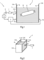
- Fig.1 shows a sectional view in side view of a simplified sketch of a PEF cooking device 1.
- the PEF cooking device 1 has a food container 2 with, for example, a rectangular wall 3.
- a first metallic PEF electrode 4a and a second metallic PEF electrode 4b are arranged on two opposite wall sections (here: a left side wall 3a and a right side wall 3b).
- the PEF electrodes 4a and 4b are plate-shaped and aligned vertically and parallel to one another.
- the PEF electrodes 4a, 4b represent wall areas of the wall 3 and are exposed on the inside and outside.
- Pulsed PEF high-voltage signals PS can be applied to the PEF electrodes 4a, 4b by means of a PEF signal generator 5 in a generally known manner.
- the food container 2 can be filled with water W and food G (here, for example, in the form of a sausage), whereby it should be filled at least up to a minimum (target) level hmin.
- the water W or the food 2 to be cooked contacts the PEF electrodes 4a, 4b that are exposed on the inside.
- the PEF signal generator 5 can be controlled in a generally known manner via a control device 6, so that, for example, an energy input into the water W and the food G can be adjusted, for example by changing a frequency of the PEF signals PS.
- the PEF cooking device 1 also has a non-contact temperature-measuring IR sensor 7 arranged on the outside of the food container 2, which is connected to the control device 6 via a galvanically isolating interface 8.
- a non-contact temperature-measuring IR sensor 7 arranged on the outside of the food container 2, which is connected to the control device 6 via a galvanically isolating interface 8.
- the measurement signals generated by the IR sensor 7 or further processed, e.g. digital, measurement data can be used by the control device 6 to adjust the energy input into the water W and the food G to be cooked and/or to trigger another action.
- the IR sensor7 is grounded with low resistance.
- the IR sensor 7 is here directed perpendicularly to the outside of the first PEF electrode 4a (its optical axis is therefore perpendicular to the outer surface of the first PEF electrode 4a) and is at least 1 cm away from the surface.
- the first PEF electrode 4a is therefore located on the outside in the field of vision of the IR sensor 7.
- the measuring spot present on the outer surface of the first PEF electrode 4a, which corresponds to an area of the viewing area, is arranged completely on the first PEF electrode 4a.
- the measuring spot lies below the minimum (target) filling level hmin and thus in an area of the first PEF electrode 4a which, when the food container 2 is properly filled, contacts the water W and/or the food G on the inside.
- the control device 6 can therefore also be set up to detect whether the food container 2 is sufficiently filled to carry out a cooking process (ie, for cooking or heating the food G). This can be implemented, for example, by the control device 6 recognizing whether, after applying the PEF signals PS, the temperature sensed by the IR sensor 7 reaches or exceeds a predetermined threshold value, or in the case of a current fill level h ⁇ hmin that is too low, not reached or exceeds, if necessary within a specified period of time.
- the minimum fill level hmin corresponds at least approximately to the upper edge of the measuring spot M.
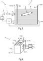
- Fig.2 shows a sketch of the food container 2 and the IR sensor 7 in an oblique view.
- the wall 3 outside the PEF electrodes 4a, 4b, and thus also the front and rear side walls 3c, 3d as well as the base, are made of electrically non-conductive material such as plastic, ceramic, etc. and therefore insulate the PEF electrodes 4a, 4b from each other.
- Fig.3 shows a sectional view in side view of a simplified sketch of a PEF cooking device 11 with a food container 12 and the IR sensor 7.
- the food container 12 differs from the food container 2 in that the first PEF electrode 6a is now arranged so that it can be moved frontally within the wall 13 , as indicated by the double arrow.
- a distance between the two PEF electrodes 6a, 4b can be adjusted, for example manually or by motor via the control device 6.
- the first PEF electrode 6a therefore no longer represents a wall area.
- the left wall side 13a here, which is located behind the first PEF electrode 6a, consists largely of electrically insulating material such as plastic, etc., over the entire surface except for a metal sheet 14 inserted into the left wall side 13a.
- the metal sheet 14 makes contact on the inside the water W and is visible to the IR sensor 7 on the outside.
- the measuring spot M of the IR sensor 7 advantageously lies completely on the metal sheet.
- the metal sheet 14 advantageously has an area which corresponds to the measuring spot M or is only slightly larger.
- Fig.4 shows a sectional view in side view of a simplified sketch of a PEF cooking device 15, of which only its food container 16 and several (here, for example, three) IR sensors 7 arranged vertically one above the other are shown.
- the IR sensors 7 are connected to the control device 6 in a similar way to the PEF cooking devices 1 and 11.
- the PEF cooking device 15 represents a modification of the PEF cooking device 11 in that the food container 16 has three inserts in the form of metal sheets 14 arranged one above the other in an arrangement analogous to the IR sensors 7, for example on a wall side 17a of the wall 17. This makes it advantageously possible, for example, to use the current one to at least approximately determine the fill level h, to detect foam formation and/or boiling over, etc.
- only one IR sensor 7 needs to be present, which, for example, is controlled by a motor using the control device 6, can be moved vertically and can thereby measure the temperatures applied to the several metal sheets 14 one after the other.
- the outer sides of the PEF electrode 4a and/or the metal sheet 14 can have a coating that lies at least in the field of view of the IR sensor 7 and has a high spectral emissivity.
Landscapes
- Engineering & Computer Science (AREA)
- Food Science & Technology (AREA)
- Physics & Mathematics (AREA)
- Electromagnetism (AREA)
- Health & Medical Sciences (AREA)
- Nutrition Science (AREA)
- Life Sciences & Earth Sciences (AREA)
- Chemical & Material Sciences (AREA)
- Polymers & Plastics (AREA)
- Cookers (AREA)
Description
- Die Erfindung betrifft ein Haushalts-PEF-Gargerät, aufweisend einen mit Flüssigkeit füllbaren Gargutbehälter mit sich gegenüberliegenden PEF-Elektroden, zwischen die Gargut einbringbar ist, einen PEF-Signalgenerator zum Anlegen von PEF-Signalen an die PEF-Elektroden und eine Steuereinrichtung zum Ansteuern des PEF-Signalgenerators.
- PEF ("Pulsed Electric Field")-Garen, d.h., das Garen von Gargut bzw. Lebensmitteln mittels gepulster Spannungspulse ("PEF-Pulsen"), ist grundsätzlich bekannt. Dabei werden die PEF-Pulse an flächige PEF-Elektroden eines Gargutbehälters angelegt, welche aufgrund der Kontaktierung der PEF-Elektroden mit dem Inhalt des Gargutbehälters einen elektrischen Strom durch den Inhalt des Gargutbehälters erzeugen. Der Inhalt umfasst typischerweise flüssiges Gargut wie Suppe oder in ein Wasserbad eingelegtes Gargut. Der erzeugte Strom fließt auch durch das Gargut, wodurch es gegart wird.
- Beispielsweise
WO 2016/008868 A1 betrifft ein Verfahren zum PEF ("Pulsed Electric Field")-Kochen eines Lebensmittelprodukts in einer Behandlungskammer, wobei die Behandlungskammer zwei gegenüberliegende Wände umfasst, die jeweils eine Elektrode bilden. Das Verfahren umfasst die folgenden Schritte: (a) Platzieren einer Menge des Lebensmittelprodukts, gegebenenfalls in einer umgebenden Flüssigkeit, in der Behandlungskammer zwischen den beiden Elektroden, so dass das Lebensmittelprodukt und / oder die umgebende Flüssigkeit in direktem Kontakt mit den Elektroden stehen; und (b) Anlegen von elektrischen Impulsen, die von einem gepulsten elektrischen Feldgenerator erzeugt werden, an die Elektroden, so dass das Lebensmittelprodukt einem gepulsten elektrischen Feld mit einer Feldstärke von 10 bis 180 V/cm ausgesetzt wird und die Gesamtkochzeit 0,5 bis 1000 s beträgt. Vorzugsweise beträgt die Zahl der Pulse 1 bis 2.000.000, und die Pulse haben jeweils eine Dauer von 1 bis 20000 Mikrosekunden. Das Lebensmittelprodukt und, falls vorhanden, die umgebende Flüssigkeit weisen eine elektrische Leitfähigkeit von 0,01 bis 10 S/m auf.WO 2016/008868 A1 betrifft auch ein Kochsystem, das zum Kochen eines Lebensmittelprodukts gemäß einem solchen Verfahren geeignet ist. -
WO 2012/125021 A1 offenbart ein System zum Behandeln eines Nahrungsmittelprodukts mittels PEF ("Pulsed Electric Field"), wobei das System ein Behandlungsgeschirr und eine Kopplungsstation, d.h., eine Andockstation eines PEP-Generators, umfasst; die Behandlungswanne eine erste und eine zweite Durchgangsöffnung, einen abnehmbaren Deckel, eine Masseelektrode, eine Spannungselektrode, eine erste Stromleitung, eine zweite Stromleitung umfasst, wobei sich die erste Stromleitung durch die erste Durchgangsöffnung nach außen erstreckt und die zweite Stromleitung sich durch die zweite Durchgangsöffnung nach außen erstreckt; die Kupplungsstation zur Aufnahme der Behandlungspfanne in Gebrauchsstellung zur Behandlung von Lebensmitteln eingerichtet ist, die Kupplungsstation Verbindungsleitungen zum PEP-Generator derart aufweist, dass in der Gebrauchsstellung der Behandlungswanne ein gepulstes elektrisches Feld vom PEF-Generator auf die Elektroden in der Behandlungswanne übertragen wird. -
EP 1 669 677 A1 offenbart ein Kochfeld mit einer Kochfeldplatte zum Abstellen zumindest eines Gargutbehältnisses, die durch zumindest eine Leiste begrenzt ist, und mit zumindest einem Temperatursensor zum Ermitteln einer Garguttemperatur. Um in konstruktiv einfacher Weise eine Temperaturerfassung des Garguts zu ermöglichen ist der Temperatursensor außerhalb der Kochfeldplatte im Bereich der Leiste angeordnet. -
EP 0 772 991 A1 offenbart eine sensorgesteuerte Garungseinheit, bestehend aus Gargerät, Sensorik und Kochfeld, wobei ein der sensorgesteuerten Garungseinheit zugeordneter Infrarotsensor kochstellenbezogen leicht erhöht oberhalb des Kochfeldes angeordnet und in einer konstruktiven Funktionseinheit integriert ist, so dass in der sensorgesteuerten Garungseinheit Kochfeld, Gargerät und Sensorik systemhaft miteinander verbunden, aufeinander angepasst und optimiert sind, dass das Gargerät ein Systemtopf mit einem normierten Emissionsfaktor ist, dass der Systemtopf optimierte Topfwand- und Topfboden-Dickenbereiche einhält, und dass der Systemtopf eine angepasste Kontaktstelle zwischen Topfdeckel und Topfrand besitzt. - Bei PEF-Garen, wie auch bei anderen Garverfahren, ist es vorteilhaft, wenn ein Garfortschritt überwachbar ist, z.B. um während des PEF-Garens Betriebsparameter anzupassen (z.B. um eine Art und einen Umfang der Energiezufuhr anzupassen, beispielsweise über eine Variation einer Dauer und/oder Frequenz der PEF-Pulse) um einen Eintritt eines Garendes besonders genau zu ermitteln und/oder um bei einem Eintritt ungeplanter Entwicklungen korrigierend in den Garprozess einzugreifen. Dazu werden häufig Sensoren eingesetzt. Beim Einsatz von Sensoren, die an einem entnehmbaren Gargutbehälter angeordnet sind, tritt dabei das Problem auf, dass die durch die Spannungspulse bereitgestellte Hochspannung (die mehrere hundert Volt betragen kann) über Sensoren nicht in das (übrige) PEF-Gargerät verschleppt werden darf.
- Es ist die Aufgabe der vorliegenden Erfindung, die Nachteile des Standes der Technik zumindest teilweise zu überwinden und insbesondere eine Möglichkeit bereitzustellen, an einem Gargutbehälter angeordnete Sensoren auf eine betriebssichere und nutzerfreundliche Weise zu betreiben.
- Diese Aufgabe wird gemäß den Merkmalen des Anspruchs 1 gelöst. Vorteilhafte Ausführungsformen sind Gegenstand der abhängigen Ansprüche, der Beschreibung und der Zeichnungen.
- Die Aufgabe wird gelöst durch ein Haushalts-PEF-Gargerät, aufweisend
- einen mit Flüssigkeit füllbaren Gargutbehälter mit sich gegenüberliegenden PEF-Elektroden, zwischen die Gargut einbringbar ist,
- einen PEF-Signalgenerator zum Anlegen von PEF-Signalen an die PEF-Elektroden,
- eine Steuereinrichtung zum Ansteuern des PEF-Signalgenerators und
- mindestens einen von den PEF-Elektroden beabstandeten, berührungslos messenden IR-Sensor, der mit der Steuereinrichtung verbunden ist,
- ein Messfleck des IR-Sensors eine Außenseite eines elektrisch leitfähigen Bereichs einer Wandung des Gargutbehälters umfasst, welcher bei gefülltem Gargutbehälter innenseitig durch die Flüssigkeit kontaktierbar ist.
- So ergibt sich der Vorteil, dass mit Hilfe der von dem mindestens einen IR-Sensor ausgegebenen Sensorsignale eine Temperatur der in dem Gargutbehälter befindlichen Flüssigkeit mit geringer zeitlicher Latenz und hoher Genauigkeit berührungslos gemessen werden kann. Dabei wird ausgenutzt, dass elektrisch leitfähiges Material auch eine sehr hohe thermische Leitfähigkeit besitzt und dadurch die innenseitig an dem im Messfleck des IR-Sensors liegenden Wandungsbereich anliegende Temperatur der Flüssigkeit mit nur geringem Versatz und geringer zeitlicher Verzögerung an der Außenseite des Wandungsbereichs anliegt.
- Dadurch wiederum kann vorteilhafterweise die mittels der Steuereinrichtung in den Gargutbehälter über die PEF-Signale eingegebene Energiezufuhr beruhend auf den Sensorsignalen prozessbegleitend modifiziert, z.B. für eine Temperaturregelung der Flüssigkeit.
- Ein weiterer Vorteil besteht darin, dass aufgrund der berührungslosen Messung ein Überschlag der an den PEF-Elektroden anliegenden Hochspannung auf den IR-Sensor, und weiter auf mit dem IR-Sensor galvanisch verbundene Bauteile, sicher vermieden wird.
- Das Haushalts-PEF-Gargerät dient auf grundsätzlich bekannte Weise dazu, zwischen den PEF-Elektroden befindliches Gargut durch Stromfluss zu garen oder zu erwärmen.
- Die PEF-Elektroden sind elektrisch leitfähig, typischerweise metallisch, und kontaktieren direkt die Flüssigkeit oder das Gargut. Die PEF-Elektroden können plattenförmig ausgebildet ("Kontaktplatten") sein. Sie sind insbesondere parallel zueinander ausgerichtet. Sie können z.B. vertikal ausgerichtet sein.
- Die sich gegenüberliegenden PEF-Elektroden sind voneinander elektrisch isoliert und bilden einen Kondensator. Die daran angelegten PEF-Signale sind insbesondere gepulste Hochspannungssignale. Speziell können die PEF-Signale gepulste Wechselspannungs-signal(e) sein.
- Die Flüssigkeit kann z.B. Wasser oder eine wasserbasierte Flüssigkeit (z.B. Suppe) sein.
- Mittels der Steuereinrichtung lassen sich die PEF-Signale variieren, z.B. in Bezug auf ihre Frequenz, und damit auch ein Energieeintrag in die Flüssigkeit und das Gargut.
- Dadurch, dass der mindestens eine IR-Sensor mit der Steuereinrichtung verbunden ist, kann die Steuereinrichtung die abgefühlte Temperatur als Eingangsgröße nutzen, z.B. zur Variation der PEF-Signale (beispielsweise für eine Temperaturregelung) und/oder für eine Situationsüberwachung. So kann die Steuereinrichtung dazu eingerichtet sein, beruhend aus den empfangenden Temperatursignalen oder daraus abgeleiteten Temperaturdaten zu erkennen, ob sich in dem Gargutbehälter überhaupt Flüssigkeit befindet. Dies kann dadurch umgesetzt sein, dass während einer insbesondere anfänglichen Aufheizphase überprüft wird, ob sich die abgefühlte Temperatur innerhalb einer vorgegebenen Zeitdauer ausreichend erhöht (z.B. eine Temperaturdifferenz innerhalb der vorgegebenen Zeitdauer höher ist als ein vorgegebener Schwellwert). Ist dies nicht der Fall, kann auf einen zu niedrigen Füllstand geschlossen werden. Die Steuereinrichtung kann dann mindestens eine Aktion auslösen, z.B. den Garvorgang stoppen und/oder einen Hinweis an einen Nutzer ausgeben.
- Unter einem Messfleck kann insbesondere derjenige Bereich an der Außenseite der Wandung verstanden werden, der innerhalb des Sichtfelds eines IR-Sensors liegt. Zumindest ein Messfleck zumindest eines Sensors sollte bei Füllung des Gargutbehälters zumindest bis zu einem Mindestfüllstand vollständig unter dem Niveau der Flüssigkeit in dem Gargutbehälter liegen.
- Es ist eine Ausgestaltung, dass zumindest eine PEF-Elektrode einen Bereich der ansonsten elektrisch isolierenden (z.B. aus Kunststoff bestehenden) Wandung darstellt und der Messfleck auf der Außenseite der PEF-Elektrode liegt. So wird der Vorteil eines besonders einfachen und preiswerten Aufbaus erreicht. In anderen Worten ist eine Außenseite zumindest einer PEF-Elektrode für den IR-Sensor von außen sichtbar, und der Messfleck befindet sich an dieser Außenseite. In noch anderen Worten sieht der IR-Sensor von au-ßen auf eine PEF-Elektrode. Zumindest die an ihrer Außenseite den Messfleck bereitstellende PEF-Elektrode ist dadurch unbeweglich an dem Gargutbehälter angeordnet
- Es ist eine Ausgestaltung, dass zumindest eine PEF-Elektrode beweglich in dem Gargutbehälter angeordnet ist und eine hinter (d.h., gegenüberliegend der dem Gargut abgewandten Seite) der beweglichen PEF-Elektrode befindliche Fläche der Wandung mindestens einen von elektrisch isolierendem Material umgebenen elektrisch leitfähigen Einsatz aufweist, der bei gefülltem Gargutbehälter innenseitig durch die Flüssigkeit kontaktiert wird und außenseitig in dem Messfleck des IR-Sensor liegt. Durch die Beweglichkeit der zumindest einen PEF-Elektrode wird der Vorteil erreicht, dass sich ein Abstand zwischen zwei gegenüberliegenden PEF-Elektroden gezielt einstellen lässt. Dadurch wiederum kann eine Impedanz an eine Leistungsfähigkeit des Pulsgenerators angepasst werden. Bei dieser Ausgestaltung befindet sich hinter einer beweglichen PEF-Elektroden eine Wand aus elektrisch isolierendem Material, z.B. Kunststoff. In diesem Fall kann der IR-Sensor nicht auf die PEF-Elektrode "sehen". Eine Abfühlung der Temperatur an der Außenseite einer vollflächig elektrisch isolierenden Wand ist nachteilig, weil sich in einer solchen Wand ein hohes Temperaturgefälle einstellt, das eine zuverlässige Messung der Temperatur der Flüssigkeit an der Innenseite der Wand verhindert. Insbesondere können schnelle Temperaturänderungen nicht erfasst werden. Durch den elektrisch leitfähigen Einsatz oder Einsatzelement (auch als "Inlay" bezeichenbar), der bzw. das innenseitig in Kontakt mit der Flüssigkeit in der Gargutbehälter steht, aber nicht als PEF-Elektrode dient, wird demgegenüber eine zuverlässige und schnell reagierende Temperaturabfühlung auch bei beweglicher PEF-Elektrode ermöglicht.
- Der Einsatz dient ausschließlich als Träger eines Messflecks für die Erfassung der Temperatur Flüssigkeit mittels des mindestens einen IR-Sensors. Seine Größe kann daher auf die Größe des Messflecks beschränkt sein, oder sogar kleiner sein als der Messfleck. Je kleiner der Einsatz bzw. dessen innenseitige Oberfläche ist, desto geringer ist vorteilhafterweise eine Beeinflussung eines elektrischen Felds innerhalb des Gargutbehälters. Insbesondere entspricht die Außenseite des Einsatzes dem Messfleck oder ist nur geringfügig größer oder kleiner.
- Es ist eine Weiterbildung, dass der Einsatz eine Metallplatte ist, z.B. ein Metallblech. Diese kann z.B. in das umgebende elektrisch isolierende Material radseitig angespritzt sein. Sie muss daher nur die Größe des Messflecks haben.
- Zur Vermeidung einer thermischen Trägheit ist der Einsatz möglichst dünn.
- Es ist eine Ausgestaltung, dass ein Abstand des IR-Sensors von den PEF-Elektroden und oder von dem Einsatz mindestens 1 cm beträgt. Durch eine solche Luftstrecke wird ein Überschlag von Hochspannung auf den IR-Sensor besonders zuverlässig verhindert.
- Es ist eine Ausgestaltung, dass eine optische Achse des IR-Sensors senkrecht zu einer Oberfläche des in dem Messfleck des IR-Sensors liegenden elektrisch leitfähigen Bereichs steht. In anderen Worten "sieht" der IR-Sensor senkrecht auf den Messfleck. Diese Anordnung ermöglicht eine besonders zuverlässige Temperaturmessung.
- Es ist eine Ausgestaltung, dass das Haushalts-PEF-Gargerät mehrere IR-Sensoren aufweist, deren Messflecke übereinander angeordnet sind. Dadurch wird der Vorteil erreicht, dass ein aktueller Füllstand (auch als Füllstandsniveau oder Pegel bezeichenbar) in dem Gargutbehälter zumindest ungefähr bestimmbar ist. Beispielsweise kann die Steuereinrichtung dazu eingerichtet sein, insbesondere während einer anfänglichen Aufheizphase zu überprüfen, ob sich die an den unterschiedlichen Messflecken bzw. durch die unterschiedlichen IR-Sensoren abgefühlte Temperatur innerhalb einer vorgegebenen Zeitdauer ausreichend erhöht (z.B. eine Temperaturdifferenz innerhalb der vorgegebenen Zeitdauer höher ist als ein vorgegebener Schwellwert). Bei den Messflecken, für die dies der Fall, kann davon ausgegangen werden, dass sie innenseitig zumindest merklich in die Flüssigkeit eintauschen und daher die Flüssigkeit bis zu dem höchsten solchen Messfleck reicht. In analoger Betrachtung kann darauf geschlossen werden, dass die Flüssigkeit nicht bis zu einem Messfleck reicht, bei dem es nicht zu einer ausreichend schnellen Erwärmung kommt. Die Steuereinrichtung kann die Kenntnis über den Füllstand z.B. dazu nutzen, die PEF-Signale zu formen bzw. einen Energieeintrag in den Gargutbehälter anzupassen.
- Die Messflecke können z.B. übereinander an einer Außenseite einer gleichen PEF-Elektrode vorhanden sein. Die Messflecke können besonders vorteilhaft auf außenseitigen Oberflächen jeweiliger getrennt übereinander angeordneter Einsätze oder Inlays liegen, da so eine Temperaturquerbeeinflussung zwischen den die Messflecke tragenden Bereichen besonders gering ist.
- Mit einer solchen Anordnung von übereinander angeordneten Messflecken kann auch eine Aufschäumerkennung und/oder Überkocherkennung umgesetzt werden: Wird im Laufe eines Garprozesses erkannt, dass sich eine Temperatur eines zunächst oberhalb des Füllstands befindlichen Messflecks merklich erhöht oder innerhalb einer vorgegebenen Zeitdauer merklich erhöht (z.B. plötzlich erhöht), kann davon ausgegangen werden, dass der zugehörige Wandungsbereich nun innenseitig mit Flüssigkeit benetzt ist. Daraus kann eine Schaumbildung und/oder ein Überkochen der Flüssigkeit erkannt werden. Die Steuereinrichtung kann dann z.B. einen Energieeintrag in den Gargutbehälter verringern.
- Es ist eine Ausgestaltung, dass das Haushalts-PEF-Gargerät einen vertikal - insbesondere motorisch - beweglichen IR-Sensor aufweist und dazu eingerichtet ist, den IR-Sensor während eines Garprozesses auf unterschiedliche vertikale Positionen zu bewegen, welche vertikal übereinander angeordneten Messflecken entsprechen. Durch zeitlich aufeinanderfolgende Abfühlung oder Messung der an den übereinander angeordneten Messflecken anliegenden Temperatur kann eine zu der oben beschriebenen Anordnung mit mehreren IR-Sensoren, deren Messflecke übereinander angeordnet sind, analoge Funktionalität noch preiswerter bereitgestellt werden.
- Es ist eine Ausgestaltung, dass der in dem Sichtfeld des IR-Sensors liegende elektrisch leitfähige Bereich der Wandung an seiner Außenseite mit einer Beschichtung versehen, welche einen hohen spektralen Emissionsgrad aufweist. Dies erhöht eine Zuverlässigkeit und Genauigkeit einer Temperaturbestimmung. Dies beruht auf der Überlegung, dass Metall zumindest in blanker oder geputzter bzw. polierter Form einen nur geringen Emissionsgrad aufweist, aber ein Emissionsgrad über den zu überwachenden Temperaturbereich (bei Kochprozessen typischerweise von etwa 0 °C bis hin zu etwa 100 °C) möglichst konstant und hoch sein.
- Es ist eine Ausgestaltung, dass der IR-Sensor (d.h., der IR-Sensor als solcher oder dessen Gehäuse) niederohmig geerdet ist. Dies kann z.B. dadurch umgesetzt sein, dass er mit einer Masseleitung einer ihn betreibenden Elektronik verbunden ist.
- Es ist eine Ausgestaltung, dass der IR-Sensor über eine galvanisch trennende Schnittstelle mit der Steuereinrichtung verbunden ist. So können Störungen oder Störsignale vermieden werden, die aufgrund von Influenzerscheinungen auftreten können (z.B. durch feldinduzierte Ladungsverschiebungen erzeugte Spannungen). Ein Beispiel für eine galvanisch trennende Schnittstelle ist die I2C-Bus-Schnittstelle, welche z.B. mittels integrierter Bauelemente vom Typ ADuM2250 oder ADuM2251 der Fa. Analog Devices umsetzbar ist.
- Die oben beschriebenen Eigenschaften, Merkmale und Vorteile dieser Erfindung sowie die Art und Weise, wie diese erreicht werden, werden klarer und deutlicher verständlich im Zusammenhang mit der folgenden schematischen Beschreibung eines Ausführungsbeispiels, das im Zusammenhang mit den Zeichnungen näher erläutert wird.
- Fig.1
- zeigt als Schnittdarstellung in Seitenansicht eine vereinfachte Skizze eines PEF-Gargeräts gemäß einem ersten Ausführungsbeispiel mit einem Gargutbehälter und einem IR-Sensor;
- Fig.2
- zeigt in Schrägansicht eine Skizze des Gargutbehälters und des IR-Sensors des PEF-Gargeräts gemäß dem ersten Ausführungsbeispiel mit dem IRSensor;
- Fig.3
- zeigt als Schnittdarstellung in Seitenansicht eine vereinfachte Skizze eines PEF-Gargeräts gemäß einem zweiten Ausführungsbeispiel mit einem Gargutbehälter und einem IR-Sensor; und
- Fig.4
- zeigt als Schnittdarstellung in Seitenansicht eine vereinfachte Skizze eines PEF-Gargeräts gemäß einem dritten Ausführungsbeispiel mit einem Gargutbehälter und mehreren IR-Sensoren.
-
Fig.1 zeigt als Schnittdarstellung in Seitenansicht eine vereinfachte Skizze eines PEF-Gargeräts 1. Das PEF-Gargerät 1 weist einen Gargutbehälter 2 mit beispielsweise rechteckiger Wandung 3 auf. An zwei gegenüberliegenden Wandungsabschnitten (hier: einer linken Seitenwand 3a und einer rechten Seitenwand 3b) sind eine erste metallische PEF-Elektrode 4a und eine zweite metallische PEF-Elektrode 4b angeordnet. Die PEF-Elektroden 4a und 4b sind plattenförmig ausgebildet und vertikal sowie parallel zueinander ausgerichtet. Die PEF-Elektroden 4a, 4b stellen hier Wandungsbereiche der Wandung 3 dar und liegen innenseitig und außenseitig frei. - An die PEF-Elektroden 4a, 4b sind mittels eines PEF-Signalgenerators 5 gepulste PEF-Hochspannungssignale PS auf grundsätzlich bekannte Weise anlegbar. Der Gargutbehälter 2 ist mit Wasser W und Gargut G (hier z.B. in Form eines Würstchens) füllbar, wobei er hier zumindest bis zu einem minimalen (Soll-)Füllstand hmin gefüllt werden sollte. Das Wasser W bzw. das Gargut 2 kontaktiert die innenseitig freiliegenden PEF-Elektroden 4a, 4b.
- Der PEF-Signalgenerator 5 ist auf grundsätzlich bekannte Weise über eine Steuereinrichtung 6 ansteuerbar, so dass dadurch z.B. ein Energieeintrag in das Wasser W und das Gargut G anpassbar ist, beispielsweise über eine Änderung einer Frequenz der PEF-Signale PS.
- Das PEF-Gargerät 1 weist ferner einen außenseitig des Gargutbehälters 2 angeordneten, berührungslos temperaturmessenden IR-Sensor 7 auf, der über eine galvanisch trennende Schnittstelle 8 mit der Steuereinrichtung 6 verbunden ist. Dadurch können die von dem IR-Sensor 7 erzeugten Messsignale bzw. darauf weiterverarbeitete, z.B. digitale, Messdaten von der Steuereinrichtung 6 dazu verwendet werden, den Energieeintrag in das Wasser W und das Gargut G anzupassen und/oder eine andere Aktion auszulösen. Der IR-Sensor7 ist niederohmig geerdet.
- Der IR-Sensor 7 ist hier senkrecht auf die Außenseite der ersten PEF-Elektrode 4a gerichtet (seine optische Achse steht also senkrecht auf der äußeren Oberfläche der ersten PEF-Elektrode 4a) und dabei mindestens 1 cm von der Oberfläche entfernt. Die erste PEF-Elektrode 4a liegt somit im Sichtfeld des IR-Sensors 7 eine Außenseite. Der auf der äußeren Oberfläche der ersten PEF-Elektrode 4a vorhandene Messfleck, der dort einer Fläche des Sichtbereichs entspricht, ist dabei vollständig auf der ersten PEF-Elektrode 4a angeordnet.
- Insbesondere liegt der Messfleck unterhalb des minimalen (Soll-)Füllstands hmin und damit in einem Bereich der ersten PEF-Elektrode 4a, der bei ordnungsgemäßer Füllung des Gargutbehälters 2 auf der Innenseite das Wasser W und/oder das Gargut G kontaktiert. Die Steuereinrichtung 6 kann daher auch dazu eingerichtet sein, zu erkennen, ob der Gargutbehälter 2 zur Durchführung eines Garprozessen (d.h., zum Garen oder Erwärmen des Garguts G) ausreichend gefüllt ist. Dies kann z.B. dadurch umgesetzt sein, dass die Steuereinrichtung 6 erkennt, ob nach Anlegen der PEF-Signale PS die mittels des IR-Sensors 7 abgefühlte Temperatur einen vorgegebenen Schwellwert erreicht oder überschreitet, oder im Fall eines zu geringen aktuellen Füllstands h < hmin nicht erreicht oder überschreitet, ggf. innerhalb einer vorgegebenen Zeitdauer. Vorteilhafterweise entspricht der minimalen Füllstand hmin dazu zumindest ungefähr mit dem oberen Rand des Messflecks M.
-
Fig.2 zeigt eine Skizze des Gargutbehälters 2 und des IR-Sensors 7 in Schrägansicht. Die Wandung 3 außerhalb der PEF-Elektroden 4a, 4b, und damit auch die vorderen und rückwärtigen Seitenwände 3c, 3d sowie der Boden, sind aus elektrisch nichtleitendem Material wie Kunststoff, Keramik usw. und isolieren daher die PEF-Elektroden 4a, 4b voneinander. -
Fig.3 zeigt als Schnittdarstellung in Seitenansicht eine vereinfachte Skizze eines PEF-Gargeräts 11 mit einem Gargutbehälter 12 und dem IR-Sensor 7. Der Gargutbehälter 12 unterscheidet sich von dem Gargutbehälter 2 dadurch, dass die erste PEF-Elektrode 6a nun frontalverschieblich innerhalb der Wandung 13 angeordnet ist, wie durch den Doppelpfeil angedeutet. Dadurch kann ein Abstand zwischen den beiden PEF-Elektroden 6a, 4b eingestellt werden, z.B. manuell oder motorisch über die Steuereinrichtung 6. Die erste PEF-Elektrode 6a stellt also keinen Wandungsbereich mehr dar. - Vielmehr besteht die hier linke Wandungsseite 13a, die sich hinter der ersten PEF-Elektrode 6a befindet, weitgehend vollflächig aus elektrisch isolierendem Material wie Kunststoff usw., d.h., vollflächig bis auf ein in die linke Wandungsseite 13a eingesetztes Metallblech 14. Das Metallblech 14 kontaktiert innenseitig das Wasser W und ist außenseitig für den IR-Sensor 7 sichtbar. Der Messfleck M des IR-Sensors 7 liegt vorteilhafterweise vollständig auf dem Metallblech. Zur Vermeidung einer merklichen Beeinflussung des innerhalb des Gargutbehälters 12 bei angelegten PEF-Signalen PS bestehenden elektrischen Felds weist das Metallblech 14 vorteilhafterweise eine Fläche auf, die dem Messfleck M entspricht oder nur geringfügig größer ist.
-
Fig.4 zeigt als Schnittdarstellung in Seitenansicht eine vereinfachte Skizze eines PEF-Gargeräts 15, von dem nur dessen Gargutbehälter 16 und mehrere (hier beispielhaft drei) vertikal übereinander angeordnete IR-Sensoren 7 eingezeichnet sind. Die IR-Sensoren 7 sind analog zu den PEF-Gargeräten 1 und 11 mit der Steuereinrichtung 6 verbunden. - Das PEF-Gargerät 15 stellt eine Abwandlung des PEF-Gargeräts 11 dahingehend dar, dass der Gargutbehälter 16 in zu den IR-Sensoren 7 analogen Anordnung an z.B. einer Wandungsseite 17a der Wandung 17 drei übereinander angeordnete Einsätze in Form von Metallblechen 14 aufweist. Dadurch ist es vorteilhafterweise z.B. möglich, den aktuellen Füllstand h zumindest ungefähr zu bestimmen, eine Schaumbildung und/oder ein Überkochen zu erkennen, usw.
- In einer alternativen, funktional analogen Weiterbildung braucht nur ein IR-Sensor 7 vorhanden zu sein, der, z.B. motorisch mittels der Steuereinrichtung 6 gesteuert, vertikal verfahrbar ist und dadurch die an den mehreren Metallblechen 14 anliegenden Temperaturen nacheinander messen kann.
- Selbstverständlich ist die vorliegende Erfindung nicht auf das gezeigte Ausführungsbeispiel beschränkt.
- So können die Außenseiten der PEF-Elektrode 4a und/oder des Metallblechs 14 eine zumindest in dem Sichtfeld des IR-Sensors 7 liegende Beschichtung aufweisen, welche einen hohen spektralen Emissionsgrad aufweist.
-
- 1
- PEF-Gargerät
- 2
- Gargutbehälter
- 3
- Wandung
- 3a-3b
- Wandungsseiten
- 4a
- Erste PEF-Elektrode
- 4b
- Zweite PEF-Elektrode
- 5
- PEF-Signalgenerator
- 6
- Steuereinrichtung
- 7
- IR-Sensor
- 8
- Galvanisch trennende Schnittstelle
- 11
- PEF-Gargerät
- 12
- Gargutbehälter
- 13
- Wandung
- 13a
- Wandungsseite
- 14
- Metallblech
- 15
- PEF-Gargerät
- 16
- Gargutbehälter
- 17
- Wandung
- 17a
- Wandungsseite
- G
- Gargut
- h
- Füllstand
- hmin
- Minimaler Füllstand
- PS
- PEF-Signal
- W
- Wasser
Claims (10)
- Haushalts-PEF-Gargerät (1; 11; 15), aufweisend- einen mit Flüssigkeit (W) füllbaren Gargutbehälter (2; 12; 16) mit sich gegenüberliegenden PEF-Elektroden (4a, 4b; 6a, 4b), zwischen die Gargut (G) einbringbar ist,- einen PEF-Signalgenerator (5) zum Anlegen von PEF-Signalen (PS) an die PEF-Elektroden (4a, 4b; 6a, 4b),- eine Steuereinrichtung (6) zum Ansteuern des PEF-Signalgenerators (5) und- mindestens einen von den PEF-Elektroden (4a, 4b; 6a, 4b) beabstandeten, berührungslos messenden IR-Sensor (7), der mit der Steuereinrichtung (6) verbunden ist,wobei- ein Messfleck (M) des IR-Sensors (7) eine Außenseite eines elektrisch leitfähigen Bereichs (4a; 14) einer Wandung (3; 12; 17) des Gargutbehälters (2; 12; 16) umfasst, welcher bei gefülltem Gargutbehälter (2) innenseitig durch die Flüssigkeit (W) kontaktierbar ist.
- Haushalts-PEF-Gargerät (1) nach Anspruch 1, wobei zumindest eine PEF-Elektrode (4a, 4b) einen Bereich einer ansonsten elektrisch isolierenden Wandung (3; 12; 17) darstellt und der Messfleck (M) des IR-Sensors (7) auf der PEF-Elektrode (4a) liegt.
- Haushalts-PEF-Gargerät (11; 15) nach Anspruch 1, wobei- zumindest eine PEF-Elektrode (6a) beweglich in dem Gargutbehälter (2) angeordnet ist und- eine hinter der beweglichen PEF-Elektrode (6a) befindliche Fläche (13a; 17a) der Wandung (13; 17) mindestens einen von elektrisch isolierendem Material umgebenen elektrisch leitfähigen Einsatz (14) aufweist, der bei innenseitig durch die Flüssigkeit (W) kontaktierbar ist und außenseitig zumindest teilweise in dem Messfleck (M) des IR-Sensors (7) liegt.
- Haushalts-PEF-Gargerät (1; 11; 15) nach einem der vorhergehenden Ansprüche, wobei ein Abstand des IR-Sensors (7) von den PEF-Elektroden (4a, 4b; 6a, 6b) und/oder von dem Einsatz (14) mindestens 1 cm beträgt.
- Haushalts-PEF-Gargerät (1; 11; 15) nach einem der vorhergehenden Ansprüche, wobei eine optische Achse des IR-Sensors (7) senkrecht zu einer Oberfläche des in dem Messfleck (M) des IR-Sensors (7) liegenden elektrisch leitfähigen Bereichs (3a; 14) steht.
- Haushalts-PEF-Gargerät (1) nach einem der vorhergehenden Ansprüche, aufweisend mehrere IR-Sensoren (7), deren Messflecke (M) übereinander angeordnet sind.
- Haushalts-PEF-Gargerät (1) nach einem der vorhergehenden Ansprüche, aufweisend einen vertikal beweglichen IR-Sensor (7), wobei das Haushalts-PEF-Gargerät (1) dazu eingerichtet ist, den IR-Sensor (7) auf unterschiedliche vertikale Positionen zu bewegen, die vertikal übereinander angeordneten Messflecken (M) entsprechen.
- Haushalts-PEF-Gargerät (1) nach einem der vorhergehenden Ansprüche, wobei der in dem Messfleck (M) des IR-Sensors (7) liegende elektrisch leitfähige Bereich (3a; 14) der Wandung (3a; 13a; 17a) an seiner Außenseite mit einer Beschichtung versehen, welche einen hohen spektralen Emissionsgrad aufweist.
- Haushalts-PEF-Gargerät (1) nach einem der vorhergehenden Ansprüche, wobei der IR-Sensor (7) niederohmig geerdet ist.
- Haushalts-PEF-Gargerät (1) nach einem der vorhergehenden Ansprüche, wobei der IR-Sensor (7) über eine galvanisch trennende Schnittstelle (8) mit der Steuereinrichtung (6) verbunden ist.
Applications Claiming Priority (2)
| Application Number | Priority Date | Filing Date | Title |
|---|---|---|---|
| DE102020203520.2A DE102020203520A1 (de) | 2020-03-19 | 2020-03-19 | Haushalts-PEF-Gargerät |
| PCT/EP2021/055289 WO2021185580A1 (de) | 2020-03-19 | 2021-03-03 | Haushalts-pef-gargerät |
Publications (2)
| Publication Number | Publication Date |
|---|---|
| EP4120876A1 EP4120876A1 (de) | 2023-01-25 |
| EP4120876B1 true EP4120876B1 (de) | 2024-01-10 |
Family
ID=74859429
Family Applications (1)
| Application Number | Title | Priority Date | Filing Date |
|---|---|---|---|
| EP21710229.2A Active EP4120876B1 (de) | 2020-03-19 | 2021-03-03 | Haushalts-pef-gargerät |
Country Status (5)
| Country | Link |
|---|---|
| US (1) | US12495924B2 (de) |
| EP (1) | EP4120876B1 (de) |
| CN (1) | CN115209769A (de) |
| DE (1) | DE102020203520A1 (de) |
| WO (1) | WO2021185580A1 (de) |
Families Citing this family (2)
| Publication number | Priority date | Publication date | Assignee | Title |
|---|---|---|---|---|
| EP4159093B1 (de) * | 2021-10-04 | 2026-01-28 | BSH Hausgeräte GmbH | Integriertes kochsystem |
| CN116473431B (zh) * | 2023-05-16 | 2024-05-24 | 珠海格力电器股份有限公司 | 烹饪控制方法、装置、介质及烹饪设备 |
Citations (8)
| Publication number | Priority date | Publication date | Assignee | Title |
|---|---|---|---|---|
| ITPN930037A1 (it) | 1993-06-08 | 1994-12-08 | Zeltron Spa | Apparecchio di cottura con controllo a distanza della temperatura di cibi in pentola, e pentola relativa. |
| EP0772991A1 (de) | 1995-11-08 | 1997-05-14 | Bosch-Siemens HausgerÀ¤te GmbH | Sensorgesteuerte Garungseinheit |
| EP1669677A1 (de) | 2004-12-08 | 2006-06-14 | BSH Bosch und Siemens Hausgeräte GmbH | Kochfeld |
| WO2012125021A1 (en) | 2011-03-11 | 2012-09-20 | IXL NEDERLAND B.V. et al. | System for treating a food product |
| WO2015005793A1 (en) | 2013-07-12 | 2015-01-15 | Ixl Netherlands B.V. | Process for batchwise cooking of a food product using a pulsed electric field and cooking system for such process |
| WO2016008868A1 (en) | 2014-07-14 | 2016-01-21 | Ixl Netherlands B.V. | Low field strength PEF cooking |
| EP3503678A1 (de) | 2017-12-22 | 2019-06-26 | BSH Hausgeräte GmbH | Gepulste elektrische feldgarvorrichtung |
| EP3572730A2 (de) | 2018-05-02 | 2019-11-27 | Elatronic Ag | Ferntemperaturmessung von kochgeschirr durch eine keramische glasplatte mit einem infrarotsensor |
Family Cites Families (8)
| Publication number | Priority date | Publication date | Assignee | Title |
|---|---|---|---|---|
| JP2004055199A (ja) * | 2002-07-17 | 2004-02-19 | Yamamoto Vinita Co Ltd | 流動性食品の高周波による連続加熱装置 |
| DE102013214851A1 (de) * | 2013-07-30 | 2015-02-05 | BSH Bosch und Siemens Hausgeräte GmbH | Gargutsensor |
| HK1245719B (zh) * | 2014-12-12 | 2019-10-25 | Digital Alloys Incorporated | 金属结构的增材制造 |
| DE102015215772A1 (de) * | 2015-08-19 | 2017-02-23 | BSH Hausgeräte GmbH | Kerntemperaturfühler, Mikrowellen-Gargerät und System |
| US10852005B2 (en) * | 2015-10-22 | 2020-12-01 | Electrolux Appliances Aktiebolag | Method and household appliance for controlling humidity |
| US11160145B2 (en) * | 2017-09-29 | 2021-10-26 | Nxp Usa, Inc. | Drawer apparatus for radio frequency heating and defrosting |
| KR20190089557A (ko) * | 2018-01-23 | 2019-07-31 | 금오공과대학교 산학협력단 | 적외선 센서를 이용한 쿠킹 타이머 |
| DE102018221814A1 (de) | 2018-12-14 | 2020-06-18 | BSH Hausgeräte GmbH | PEF-Gargerät und PEF-System |
-
2020
- 2020-03-19 DE DE102020203520.2A patent/DE102020203520A1/de active Pending
-
2021
- 2021-03-03 CN CN202180021742.0A patent/CN115209769A/zh active Pending
- 2021-03-03 EP EP21710229.2A patent/EP4120876B1/de active Active
- 2021-03-03 WO PCT/EP2021/055289 patent/WO2021185580A1/de not_active Ceased
- 2021-03-03 US US17/796,279 patent/US12495924B2/en active Active
Patent Citations (8)
| Publication number | Priority date | Publication date | Assignee | Title |
|---|---|---|---|---|
| ITPN930037A1 (it) | 1993-06-08 | 1994-12-08 | Zeltron Spa | Apparecchio di cottura con controllo a distanza della temperatura di cibi in pentola, e pentola relativa. |
| EP0772991A1 (de) | 1995-11-08 | 1997-05-14 | Bosch-Siemens HausgerÀ¤te GmbH | Sensorgesteuerte Garungseinheit |
| EP1669677A1 (de) | 2004-12-08 | 2006-06-14 | BSH Bosch und Siemens Hausgeräte GmbH | Kochfeld |
| WO2012125021A1 (en) | 2011-03-11 | 2012-09-20 | IXL NEDERLAND B.V. et al. | System for treating a food product |
| WO2015005793A1 (en) | 2013-07-12 | 2015-01-15 | Ixl Netherlands B.V. | Process for batchwise cooking of a food product using a pulsed electric field and cooking system for such process |
| WO2016008868A1 (en) | 2014-07-14 | 2016-01-21 | Ixl Netherlands B.V. | Low field strength PEF cooking |
| EP3503678A1 (de) | 2017-12-22 | 2019-06-26 | BSH Hausgeräte GmbH | Gepulste elektrische feldgarvorrichtung |
| EP3572730A2 (de) | 2018-05-02 | 2019-11-27 | Elatronic Ag | Ferntemperaturmessung von kochgeschirr durch eine keramische glasplatte mit einem infrarotsensor |
Also Published As
| Publication number | Publication date |
|---|---|
| WO2021185580A1 (de) | 2021-09-23 |
| CN115209769A (zh) | 2022-10-18 |
| US12495924B2 (en) | 2025-12-16 |
| EP4120876A1 (de) | 2023-01-25 |
| DE102020203520A1 (de) | 2021-09-23 |
| US20230082441A1 (en) | 2023-03-16 |
Similar Documents
| Publication | Publication Date | Title |
|---|---|---|
| EP1324036B1 (de) | Messvorrichtung zum Messen des Zustandes von Ölen und Fetten | |
| EP4120876B1 (de) | Haushalts-pef-gargerät | |
| EP1573280A1 (de) | Vorrichtung und verfahren zur kapazit tsmessung sowie einric htung zum ermitteln des f llstandes einer fl ssigkeit m it einer solchen vorrichtung | |
| DE60116609T2 (de) | Flüssigkeit enthaltendes heizelement und verfahren zum erfassen von temperaturveränderungen | |
| DE202010017455U1 (de) | Vorrichtung zur kapazitiven Bestimmung eines Füllstandes einer Flüssigkeit in einem Behälter | |
| EP3614797B1 (de) | Heizeinrichtung und verfahren zum betrieb einer heizeinrichtung | |
| WO2019011595A1 (de) | Kapazitives messverfahren und füllstandsmessgerät | |
| DE10256064A1 (de) | Verfahren und Vorrichtung zur Bestimmung des Wassergehalts und der Leitfähigkeit in Böden und Schüttgütern | |
| WO2008064898A1 (de) | Verfahren zum erzeugen, verarbeiten und auswerten eines mit der temperatur korrelierten signals und entsprechende vorrichtung | |
| DE102006029578A1 (de) | Verdampfereinrichtung, Auswertungsvorrichtung sowie Verfahren zum Betrieb einer Verdampfereinrichtung | |
| DE19646826C2 (de) | Vorrichtung zur Temperaturmessung an Kochstellen | |
| DE10100624B4 (de) | System zur Fluidstandsmessung | |
| DE4413979C2 (de) | Sensorgesteuerte Garungseinheit und Gargerät | |
| DE10063557B4 (de) | Verfahren und Vorrichtung zum Messen von Pegelständen | |
| DE102007049526A1 (de) | Vorrichtung zur Bestimmung und/oder Überwachung einer Prozessgröße | |
| DE102010062512A1 (de) | Beheizbarer Garraumeinschub, Gargerät und Verfahren zum Messen einer Temperatur | |
| DE1295867B (de) | Verfahren und Vorrichtung zur Abtastung von Fuellstaenden in Fluessigkeitsbehaeltern | |
| DE102005045872A1 (de) | Verfahren zum Erzeugen, Verarbeiten und Auswerten eines mit der Temperatur korrelierten Signals und entsprechende Vorrichtung | |
| EP2459974B1 (de) | Vorrichtung und verfahren zur bestimmung einer physikalischen grösse eines kapazitiven näherungsschalters | |
| DE102010062507A1 (de) | Heizvorrichtung für ein Haushaltsgerät und Haushaltsgerät mit einer solchen Heizvorrichtung | |
| DE19707664A1 (de) | Vorrichtung und Verfahren zur Steuerung oder Regelung der Temperatur von beheizten Flächen | |
| EP3339827B1 (de) | Kerntemperaturfühler für ein gargerät, verfahren zur setzerkennung eines kerntemperaturfühlers sowie verfahren zur bestimmung der wärmeleitfähigkeit eines gargeräts | |
| DE602004007542T2 (de) | Vorrichtung zum berührungsfreien messen der Leitfähigkeit von Wasser | |
| DE19734960A1 (de) | Kochzone | |
| WO2023006375A1 (de) | Pulsed electric field (pef) sensorvorrichtung, pef-system und verfahren |
Legal Events
| Date | Code | Title | Description |
|---|---|---|---|
| STAA | Information on the status of an ep patent application or granted ep patent |
Free format text: STATUS: UNKNOWN |
|
| STAA | Information on the status of an ep patent application or granted ep patent |
Free format text: STATUS: THE INTERNATIONAL PUBLICATION HAS BEEN MADE |
|
| PUAI | Public reference made under article 153(3) epc to a published international application that has entered the european phase |
Free format text: ORIGINAL CODE: 0009012 |
|
| STAA | Information on the status of an ep patent application or granted ep patent |
Free format text: STATUS: REQUEST FOR EXAMINATION WAS MADE |
|
| 17P | Request for examination filed |
Effective date: 20221019 |
|
| AK | Designated contracting states |
Kind code of ref document: A1 Designated state(s): AL AT BE BG CH CY CZ DE DK EE ES FI FR GB GR HR HU IE IS IT LI LT LU LV MC MK MT NL NO PL PT RO RS SE SI SK SM TR |
|
| DAV | Request for validation of the european patent (deleted) | ||
| DAX | Request for extension of the european patent (deleted) | ||
| GRAP | Despatch of communication of intention to grant a patent |
Free format text: ORIGINAL CODE: EPIDOSNIGR1 |
|
| STAA | Information on the status of an ep patent application or granted ep patent |
Free format text: STATUS: GRANT OF PATENT IS INTENDED |
|
| INTG | Intention to grant announced |
Effective date: 20230907 |
|
| GRAS | Grant fee paid |
Free format text: ORIGINAL CODE: EPIDOSNIGR3 |
|
| GRAA | (expected) grant |
Free format text: ORIGINAL CODE: 0009210 |
|
| STAA | Information on the status of an ep patent application or granted ep patent |
Free format text: STATUS: THE PATENT HAS BEEN GRANTED |
|
| AK | Designated contracting states |
Kind code of ref document: B1 Designated state(s): AL AT BE BG CH CY CZ DE DK EE ES FI FR GB GR HR HU IE IS IT LI LT LU LV MC MK MT NL NO PL PT RO RS SE SI SK SM TR |
|
| REG | Reference to a national code |
Ref country code: GB Ref legal event code: FG4D Free format text: NOT ENGLISH |
|
| REG | Reference to a national code |
Ref country code: CH Ref legal event code: EP |
|
| REG | Reference to a national code |
Ref country code: DE Ref legal event code: R096 Ref document number: 502021002435 Country of ref document: DE |
|
| REG | Reference to a national code |
Ref country code: IE Ref legal event code: FG4D Free format text: LANGUAGE OF EP DOCUMENT: GERMAN |
|
| REG | Reference to a national code |
Ref country code: LT Ref legal event code: MG9D |
|
| REG | Reference to a national code |
Ref country code: NL Ref legal event code: MP Effective date: 20240110 |
|
| PG25 | Lapsed in a contracting state [announced via postgrant information from national office to epo] |
Ref country code: NL Free format text: LAPSE BECAUSE OF FAILURE TO SUBMIT A TRANSLATION OF THE DESCRIPTION OR TO PAY THE FEE WITHIN THE PRESCRIBED TIME-LIMIT Effective date: 20240110 |
|
| PG25 | Lapsed in a contracting state [announced via postgrant information from national office to epo] |
Ref country code: NL Free format text: LAPSE BECAUSE OF FAILURE TO SUBMIT A TRANSLATION OF THE DESCRIPTION OR TO PAY THE FEE WITHIN THE PRESCRIBED TIME-LIMIT Effective date: 20240110 |
|
| PG25 | Lapsed in a contracting state [announced via postgrant information from national office to epo] |
Ref country code: IS Free format text: LAPSE BECAUSE OF FAILURE TO SUBMIT A TRANSLATION OF THE DESCRIPTION OR TO PAY THE FEE WITHIN THE PRESCRIBED TIME-LIMIT Effective date: 20240510 |
|
| PG25 | Lapsed in a contracting state [announced via postgrant information from national office to epo] |
Ref country code: LT Free format text: LAPSE BECAUSE OF FAILURE TO SUBMIT A TRANSLATION OF THE DESCRIPTION OR TO PAY THE FEE WITHIN THE PRESCRIBED TIME-LIMIT Effective date: 20240110 |
|
| PG25 | Lapsed in a contracting state [announced via postgrant information from national office to epo] |
Ref country code: GR Free format text: LAPSE BECAUSE OF FAILURE TO SUBMIT A TRANSLATION OF THE DESCRIPTION OR TO PAY THE FEE WITHIN THE PRESCRIBED TIME-LIMIT Effective date: 20240411 |
|
| PG25 | Lapsed in a contracting state [announced via postgrant information from national office to epo] |
Ref country code: RS Free format text: LAPSE BECAUSE OF FAILURE TO SUBMIT A TRANSLATION OF THE DESCRIPTION OR TO PAY THE FEE WITHIN THE PRESCRIBED TIME-LIMIT Effective date: 20240410 Ref country code: HR Free format text: LAPSE BECAUSE OF FAILURE TO SUBMIT A TRANSLATION OF THE DESCRIPTION OR TO PAY THE FEE WITHIN THE PRESCRIBED TIME-LIMIT Effective date: 20240110 |
|
| PG25 | Lapsed in a contracting state [announced via postgrant information from national office to epo] |
Ref country code: ES Free format text: LAPSE BECAUSE OF FAILURE TO SUBMIT A TRANSLATION OF THE DESCRIPTION OR TO PAY THE FEE WITHIN THE PRESCRIBED TIME-LIMIT Effective date: 20240110 |
|
| PG25 | Lapsed in a contracting state [announced via postgrant information from national office to epo] |
Ref country code: RS Free format text: LAPSE BECAUSE OF FAILURE TO SUBMIT A TRANSLATION OF THE DESCRIPTION OR TO PAY THE FEE WITHIN THE PRESCRIBED TIME-LIMIT Effective date: 20240410 Ref country code: NO Free format text: LAPSE BECAUSE OF FAILURE TO SUBMIT A TRANSLATION OF THE DESCRIPTION OR TO PAY THE FEE WITHIN THE PRESCRIBED TIME-LIMIT Effective date: 20240410 Ref country code: LT Free format text: LAPSE BECAUSE OF FAILURE TO SUBMIT A TRANSLATION OF THE DESCRIPTION OR TO PAY THE FEE WITHIN THE PRESCRIBED TIME-LIMIT Effective date: 20240110 Ref country code: IS Free format text: LAPSE BECAUSE OF FAILURE TO SUBMIT A TRANSLATION OF THE DESCRIPTION OR TO PAY THE FEE WITHIN THE PRESCRIBED TIME-LIMIT Effective date: 20240510 Ref country code: HR Free format text: LAPSE BECAUSE OF FAILURE TO SUBMIT A TRANSLATION OF THE DESCRIPTION OR TO PAY THE FEE WITHIN THE PRESCRIBED TIME-LIMIT Effective date: 20240110 Ref country code: GR Free format text: LAPSE BECAUSE OF FAILURE TO SUBMIT A TRANSLATION OF THE DESCRIPTION OR TO PAY THE FEE WITHIN THE PRESCRIBED TIME-LIMIT Effective date: 20240411 Ref country code: ES Free format text: LAPSE BECAUSE OF FAILURE TO SUBMIT A TRANSLATION OF THE DESCRIPTION OR TO PAY THE FEE WITHIN THE PRESCRIBED TIME-LIMIT Effective date: 20240110 Ref country code: BG Free format text: LAPSE BECAUSE OF FAILURE TO SUBMIT A TRANSLATION OF THE DESCRIPTION OR TO PAY THE FEE WITHIN THE PRESCRIBED TIME-LIMIT Effective date: 20240110 |
|
| PG25 | Lapsed in a contracting state [announced via postgrant information from national office to epo] |
Ref country code: PT Free format text: LAPSE BECAUSE OF FAILURE TO SUBMIT A TRANSLATION OF THE DESCRIPTION OR TO PAY THE FEE WITHIN THE PRESCRIBED TIME-LIMIT Effective date: 20240510 Ref country code: PL Free format text: LAPSE BECAUSE OF FAILURE TO SUBMIT A TRANSLATION OF THE DESCRIPTION OR TO PAY THE FEE WITHIN THE PRESCRIBED TIME-LIMIT Effective date: 20240110 |
|
| PG25 | Lapsed in a contracting state [announced via postgrant information from national office to epo] |
Ref country code: SE Free format text: LAPSE BECAUSE OF FAILURE TO SUBMIT A TRANSLATION OF THE DESCRIPTION OR TO PAY THE FEE WITHIN THE PRESCRIBED TIME-LIMIT Effective date: 20240110 Ref country code: PT Free format text: LAPSE BECAUSE OF FAILURE TO SUBMIT A TRANSLATION OF THE DESCRIPTION OR TO PAY THE FEE WITHIN THE PRESCRIBED TIME-LIMIT Effective date: 20240510 Ref country code: PL Free format text: LAPSE BECAUSE OF FAILURE TO SUBMIT A TRANSLATION OF THE DESCRIPTION OR TO PAY THE FEE WITHIN THE PRESCRIBED TIME-LIMIT Effective date: 20240110 Ref country code: LV Free format text: LAPSE BECAUSE OF FAILURE TO SUBMIT A TRANSLATION OF THE DESCRIPTION OR TO PAY THE FEE WITHIN THE PRESCRIBED TIME-LIMIT Effective date: 20240110 |
|
| REG | Reference to a national code |
Ref country code: DE Ref legal event code: R026 Ref document number: 502021002435 Country of ref document: DE |
|
| PG25 | Lapsed in a contracting state [announced via postgrant information from national office to epo] |
Ref country code: DK Free format text: LAPSE BECAUSE OF FAILURE TO SUBMIT A TRANSLATION OF THE DESCRIPTION OR TO PAY THE FEE WITHIN THE PRESCRIBED TIME-LIMIT Effective date: 20240110 |
|
| PG25 | Lapsed in a contracting state [announced via postgrant information from national office to epo] |
Ref country code: SM Free format text: LAPSE BECAUSE OF FAILURE TO SUBMIT A TRANSLATION OF THE DESCRIPTION OR TO PAY THE FEE WITHIN THE PRESCRIBED TIME-LIMIT Effective date: 20240110 |
|
| PLBI | Opposition filed |
Free format text: ORIGINAL CODE: 0009260 |
|
| PG25 | Lapsed in a contracting state [announced via postgrant information from national office to epo] |
Ref country code: CZ Free format text: LAPSE BECAUSE OF FAILURE TO SUBMIT A TRANSLATION OF THE DESCRIPTION OR TO PAY THE FEE WITHIN THE PRESCRIBED TIME-LIMIT Effective date: 20240110 Ref country code: EE Free format text: LAPSE BECAUSE OF FAILURE TO SUBMIT A TRANSLATION OF THE DESCRIPTION OR TO PAY THE FEE WITHIN THE PRESCRIBED TIME-LIMIT Effective date: 20240110 |
|
| PG25 | Lapsed in a contracting state [announced via postgrant information from national office to epo] |
Ref country code: SK Free format text: LAPSE BECAUSE OF FAILURE TO SUBMIT A TRANSLATION OF THE DESCRIPTION OR TO PAY THE FEE WITHIN THE PRESCRIBED TIME-LIMIT Effective date: 20240110 |
|
| PG25 | Lapsed in a contracting state [announced via postgrant information from national office to epo] |
Ref country code: SM Free format text: LAPSE BECAUSE OF FAILURE TO SUBMIT A TRANSLATION OF THE DESCRIPTION OR TO PAY THE FEE WITHIN THE PRESCRIBED TIME-LIMIT Effective date: 20240110 Ref country code: SK Free format text: LAPSE BECAUSE OF FAILURE TO SUBMIT A TRANSLATION OF THE DESCRIPTION OR TO PAY THE FEE WITHIN THE PRESCRIBED TIME-LIMIT Effective date: 20240110 Ref country code: RO Free format text: LAPSE BECAUSE OF FAILURE TO SUBMIT A TRANSLATION OF THE DESCRIPTION OR TO PAY THE FEE WITHIN THE PRESCRIBED TIME-LIMIT Effective date: 20240110 Ref country code: EE Free format text: LAPSE BECAUSE OF FAILURE TO SUBMIT A TRANSLATION OF THE DESCRIPTION OR TO PAY THE FEE WITHIN THE PRESCRIBED TIME-LIMIT Effective date: 20240110 Ref country code: DK Free format text: LAPSE BECAUSE OF FAILURE TO SUBMIT A TRANSLATION OF THE DESCRIPTION OR TO PAY THE FEE WITHIN THE PRESCRIBED TIME-LIMIT Effective date: 20240110 Ref country code: CZ Free format text: LAPSE BECAUSE OF FAILURE TO SUBMIT A TRANSLATION OF THE DESCRIPTION OR TO PAY THE FEE WITHIN THE PRESCRIBED TIME-LIMIT Effective date: 20240110 |
|
| REG | Reference to a national code |
Ref country code: CH Ref legal event code: PL |
|
| PG25 | Lapsed in a contracting state [announced via postgrant information from national office to epo] |
Ref country code: LU Free format text: LAPSE BECAUSE OF NON-PAYMENT OF DUE FEES Effective date: 20240303 |
|
| 26 | Opposition filed |
Opponent name: SEVVY B.V. Effective date: 20241010 |
|
| PG25 | Lapsed in a contracting state [announced via postgrant information from national office to epo] |
Ref country code: MC Free format text: LAPSE BECAUSE OF FAILURE TO SUBMIT A TRANSLATION OF THE DESCRIPTION OR TO PAY THE FEE WITHIN THE PRESCRIBED TIME-LIMIT Effective date: 20240110 |
|
| PG25 | Lapsed in a contracting state [announced via postgrant information from national office to epo] |
Ref country code: MC Free format text: LAPSE BECAUSE OF FAILURE TO SUBMIT A TRANSLATION OF THE DESCRIPTION OR TO PAY THE FEE WITHIN THE PRESCRIBED TIME-LIMIT Effective date: 20240110 Ref country code: LU Free format text: LAPSE BECAUSE OF NON-PAYMENT OF DUE FEES Effective date: 20240303 |
|
| PG25 | Lapsed in a contracting state [announced via postgrant information from national office to epo] |
Ref country code: IT Free format text: LAPSE BECAUSE OF FAILURE TO SUBMIT A TRANSLATION OF THE DESCRIPTION OR TO PAY THE FEE WITHIN THE PRESCRIBED TIME-LIMIT Effective date: 20240110 |
|
| REG | Reference to a national code |
Ref country code: BE Ref legal event code: MM Effective date: 20240331 |
|
| PG25 | Lapsed in a contracting state [announced via postgrant information from national office to epo] |
Ref country code: IT Free format text: LAPSE BECAUSE OF FAILURE TO SUBMIT A TRANSLATION OF THE DESCRIPTION OR TO PAY THE FEE WITHIN THE PRESCRIBED TIME-LIMIT Effective date: 20240110 |
|
| PLAX | Notice of opposition and request to file observation + time limit sent |
Free format text: ORIGINAL CODE: EPIDOSNOBS2 |
|
| PG25 | Lapsed in a contracting state [announced via postgrant information from national office to epo] |
Ref country code: BE Free format text: LAPSE BECAUSE OF NON-PAYMENT OF DUE FEES Effective date: 20240331 |
|
| PG25 | Lapsed in a contracting state [announced via postgrant information from national office to epo] |
Ref country code: IE Free format text: LAPSE BECAUSE OF NON-PAYMENT OF DUE FEES Effective date: 20240303 |
|
| PG25 | Lapsed in a contracting state [announced via postgrant information from national office to epo] |
Ref country code: IE Free format text: LAPSE BECAUSE OF NON-PAYMENT OF DUE FEES Effective date: 20240303 Ref country code: BE Free format text: LAPSE BECAUSE OF NON-PAYMENT OF DUE FEES Effective date: 20240331 Ref country code: CH Free format text: LAPSE BECAUSE OF NON-PAYMENT OF DUE FEES Effective date: 20240331 |
|
| PGFP | Annual fee paid to national office [announced via postgrant information from national office to epo] |
Ref country code: DE Payment date: 20250331 Year of fee payment: 5 |
|
| PG25 | Lapsed in a contracting state [announced via postgrant information from national office to epo] |
Ref country code: SI Free format text: LAPSE BECAUSE OF FAILURE TO SUBMIT A TRANSLATION OF THE DESCRIPTION OR TO PAY THE FEE WITHIN THE PRESCRIBED TIME-LIMIT Effective date: 20240110 |
|
| PGFP | Annual fee paid to national office [announced via postgrant information from national office to epo] |
Ref country code: AT Payment date: 20250417 Year of fee payment: 5 |
|
| PGFP | Annual fee paid to national office [announced via postgrant information from national office to epo] |
Ref country code: FR Payment date: 20250324 Year of fee payment: 5 |
|
| PLBB | Reply of patent proprietor to notice(s) of opposition received |
Free format text: ORIGINAL CODE: EPIDOSNOBS3 |
|
| PG25 | Lapsed in a contracting state [announced via postgrant information from national office to epo] |
Ref country code: CY Free format text: LAPSE BECAUSE OF FAILURE TO SUBMIT A TRANSLATION OF THE DESCRIPTION OR TO PAY THE FEE WITHIN THE PRESCRIBED TIME-LIMIT; INVALID AB INITIO Effective date: 20210303 |
|
| PG25 | Lapsed in a contracting state [announced via postgrant information from national office to epo] |
Ref country code: HU Free format text: LAPSE BECAUSE OF FAILURE TO SUBMIT A TRANSLATION OF THE DESCRIPTION OR TO PAY THE FEE WITHIN THE PRESCRIBED TIME-LIMIT; INVALID AB INITIO Effective date: 20210303 |
|
| PG25 | Lapsed in a contracting state [announced via postgrant information from national office to epo] |
Ref country code: FI Free format text: LAPSE BECAUSE OF FAILURE TO SUBMIT A TRANSLATION OF THE DESCRIPTION OR TO PAY THE FEE WITHIN THE PRESCRIBED TIME-LIMIT Effective date: 20240110 |
|
| GBPC | Gb: european patent ceased through non-payment of renewal fee |
Effective date: 20250303 |
|
| PG25 | Lapsed in a contracting state [announced via postgrant information from national office to epo] |
Ref country code: TR Free format text: LAPSE BECAUSE OF FAILURE TO SUBMIT A TRANSLATION OF THE DESCRIPTION OR TO PAY THE FEE WITHIN THE PRESCRIBED TIME-LIMIT Effective date: 20240110 |
|
| PG25 | Lapsed in a contracting state [announced via postgrant information from national office to epo] |
Ref country code: GB Free format text: LAPSE BECAUSE OF NON-PAYMENT OF DUE FEES Effective date: 20250303 |
|
| RDAF | Communication despatched that patent is revoked |
Free format text: ORIGINAL CODE: EPIDOSNREV1 |
|
| RDAD | Information modified related to despatch of communication that patent is revoked |
Free format text: ORIGINAL CODE: EPIDOSCREV1 |