EP4120814A1 - Substrate height measuring device and substrate height measuring method - Google Patents
Substrate height measuring device and substrate height measuring method Download PDFInfo
- Publication number
- EP4120814A1 EP4120814A1 EP20924283.3A EP20924283A EP4120814A1 EP 4120814 A1 EP4120814 A1 EP 4120814A1 EP 20924283 A EP20924283 A EP 20924283A EP 4120814 A1 EP4120814 A1 EP 4120814A1
- Authority
- EP
- European Patent Office
- Prior art keywords
- measurement
- substrate
- height
- measurement position
- display
- Prior art date
- Legal status (The legal status is an assumption and is not a legal conclusion. Google has not performed a legal analysis and makes no representation as to the accuracy of the status listed.)
- Granted
Links
Images


Classifications
-
- H—ELECTRICITY
- H05—ELECTRIC TECHNIQUES NOT OTHERWISE PROVIDED FOR
- H05K—PRINTED CIRCUITS; CASINGS OR CONSTRUCTIONAL DETAILS OF ELECTRIC APPARATUS; MANUFACTURE OF ASSEMBLAGES OF ELECTRICAL COMPONENTS
- H05K13/00—Apparatus or processes specially adapted for manufacturing or adjusting assemblages of electric components
- H05K13/08—Monitoring manufacture of assemblages
- H05K13/081—Integration of optical monitoring devices in assembly lines; Processes using optical monitoring devices specially adapted for controlling devices or machines in assembly lines
- H05K13/0812—Integration of optical monitoring devices in assembly lines; Processes using optical monitoring devices specially adapted for controlling devices or machines in assembly lines the monitoring devices being integrated in the mounting machine, e.g. for monitoring components, leads, component placement
-
- G—PHYSICS
- G01—MEASURING; TESTING
- G01B—MEASURING LENGTH, THICKNESS OR SIMILAR LINEAR DIMENSIONS; MEASURING ANGLES; MEASURING AREAS; MEASURING IRREGULARITIES OF SURFACES OR CONTOURS
- G01B11/00—Measuring arrangements characterised by the use of optical techniques
- G01B11/02—Measuring arrangements characterised by the use of optical techniques for measuring length, width or thickness
- G01B11/06—Measuring arrangements characterised by the use of optical techniques for measuring length, width or thickness for measuring thickness ; e.g. of sheet material
- G01B11/0608—Height gauges
-
- G—PHYSICS
- G06—COMPUTING OR CALCULATING; COUNTING
- G06T—IMAGE DATA PROCESSING OR GENERATION, IN GENERAL
- G06T7/00—Image analysis
- G06T7/0002—Inspection of images, e.g. flaw detection
-
- H—ELECTRICITY
- H05—ELECTRIC TECHNIQUES NOT OTHERWISE PROVIDED FOR
- H05K—PRINTED CIRCUITS; CASINGS OR CONSTRUCTIONAL DETAILS OF ELECTRIC APPARATUS; MANUFACTURE OF ASSEMBLAGES OF ELECTRICAL COMPONENTS
- H05K13/00—Apparatus or processes specially adapted for manufacturing or adjusting assemblages of electric components
- H05K13/08—Monitoring manufacture of assemblages
-
- H—ELECTRICITY
- H05—ELECTRIC TECHNIQUES NOT OTHERWISE PROVIDED FOR
- H05K—PRINTED CIRCUITS; CASINGS OR CONSTRUCTIONAL DETAILS OF ELECTRIC APPARATUS; MANUFACTURE OF ASSEMBLAGES OF ELECTRICAL COMPONENTS
- H05K13/00—Apparatus or processes specially adapted for manufacturing or adjusting assemblages of electric components
- H05K13/08—Monitoring manufacture of assemblages
- H05K13/081—Integration of optical monitoring devices in assembly lines; Processes using optical monitoring devices specially adapted for controlling devices or machines in assembly lines
- H05K13/0815—Controlling of component placement on the substrate during or after manufacturing
-
- G—PHYSICS
- G01—MEASURING; TESTING
- G01B—MEASURING LENGTH, THICKNESS OR SIMILAR LINEAR DIMENSIONS; MEASURING ANGLES; MEASURING AREAS; MEASURING IRREGULARITIES OF SURFACES OR CONTOURS
- G01B11/00—Measuring arrangements characterised by the use of optical techniques
- G01B11/02—Measuring arrangements characterised by the use of optical techniques for measuring length, width or thickness
- G01B11/022—Measuring arrangements characterised by the use of optical techniques for measuring length, width or thickness by means of tv-camera scanning
-
- H—ELECTRICITY
- H05—ELECTRIC TECHNIQUES NOT OTHERWISE PROVIDED FOR
- H05K—PRINTED CIRCUITS; CASINGS OR CONSTRUCTIONAL DETAILS OF ELECTRIC APPARATUS; MANUFACTURE OF ASSEMBLAGES OF ELECTRICAL COMPONENTS
- H05K13/00—Apparatus or processes specially adapted for manufacturing or adjusting assemblages of electric components
- H05K13/04—Mounting of components, e.g. of leadless components
Definitions
- the present specification discloses techniques related to a substrate height measuring device and a substrate height measuring method.
- Patent Literature 1 discloses a method of acquiring substrate height data by excluding abnormality data from measurement data in substrate height measurement such as during teaching operation. Specifically, since a substrate formed of an epoxy or the like is a rigid body, a surface of the substrate is flat when viewed from the extreme point of view. Therefore, a measurement value of the height of the substrate measured by slightly scanning changes a little, but no abrupt change occurs. Therefore, the above-described method described in Patent Literature 1 acquires measurement data at predetermined intervals in a predetermined region while moving a substrate height measurement sensor at a constant speed, and excludes the measurement data as an abnormal value when the measurement data is not included in a predetermined range indicating normal data.
- Patent Literature 1 JP-A-2009-27015
- a circuit forming member such as a wiring pattern, a through hole, and a component is provided on a substrate.
- an identification code or the like for identifying a substrate product is attached to the substrate.
- the present specification discloses a substrate height measuring device and a substrate height measuring method capable of adjusting a measurement position at which a measurement device actually measures a height of a substrate and measuring the height of the substrate.
- the present specification discloses a substrate height measuring device including an imaging section, a setting section, and a measurement section.
- the imaging section allows an imaging device to image a region of at least a part of a clamped substrate, and the region includes a measurement planned position at which a height of the substrate is to be measured.
- the setting section allows a display device to display a substrate image imaged by the imaging section and adjusts a measurement position at which the height of the substrate is actually measured based on the measurement planned position of the substrate image displayed on the display device to set the measurement position.
- the measurement section allows a measurement device to measure the height of the substrate at the measurement position set by the setting section.
- a substrate height measuring method including an imaging step, a setting step, and a measurement step.
- an imaging device images a region of at least a part of a clamped substrate, and the region includes a measurement planned position at which a height of the substrate is to be measured.
- a display device displays a substrate image imaged in the imaging step to adjust a measurement position at which the height of the substrate is actually measured based on the measurement planned position of the substrate image displayed on the display device to set the measurement position.
- a measurement device measures the height of the substrate at the measurement position set by the setting step.
- the imaging section, the setting section, and the measurement section are provided. Therefore, the substrate height measuring device can adjust the measurement position at which the height of the substrate is actually measured based on the measurement planned position of the substrate image displayed on the display device, and thus, can allow the measurement device to measure the height of the substrate.
- the above description of the substrate height measuring device can be similarly applied to the substrate height measuring method.
- Substrate height measuring device 70 may be provided in a substrate working machine that needs to measure a height of clamped substrate 90.
- a printer, a printing inspection machine, component mounter 10, and an appearance inspector are included in the substrate working machine.
- Substrate height measuring device 70 of the present embodiment is provided in component mounter 10.
- Component mounter 10 mounts multiple components P0 on substrate 90. As illustrated in Fig. 1 , component mounter 10 includes substrate conveyance device 11, component supply device 12, component transfer device 13, part camera 14, substrate camera 15, and control device 16.
- substrate conveyance device 11 includes a belt conveyor or the like, and conveys substrate 90 in a conveyance direction (X-axis direction).
- Substrate 90 is a circuit substrate on which an electronic circuit, an electrical circuit, a magnetic circuit, and the like are formed.
- Substrate conveyance device 11 conveys substrate 90 into component mounter 10, and positions and clamps substrate 90 at a predetermined position in component mounter 10. After mounting process of multiple components P0 by component mounter 10 is completed, substrate conveyance device 11 unclamps substrate 90 and conveys substrate 90 to the outside of component mounter 10.
- Component supply device 12 supplies multiple components P0 to be mounted on substrate 90.
- Component supply device 12 includes multiple feeders 121 that are provided along the conveyance direction (X-axis direction) of substrate 90. Each of multiple feeders 121 pitch-feeds a carrier tape in which multiple components P0 are housed, so as to collectably supply components P0 at a supply position located on a distal end side of feeder 121.
- component supply device 12 can supply a relatively large electronic component (lead component or the like) as compared with a chip component or the like in a state of being disposed on a tray.
- Component transfer device 13 includes head driving device 131 and moving body 132.
- Head driving device 131 is configured to move moving body 132 in the X-axis direction and the Y-axis direction by a linear motion mechanism.
- Mounting head 20 is detachably (exchangeably) provided on moving body 132 by a clamp member.
- Mounting head 20 uses at least one holding member 30 to collect and hold component P0 supplied by component supplying device 12, and mounts component P0 on substrate 90 positioned by substrate conveyance device 11.
- holding member 30 can use a suction nozzle, a chuck, and the like.
- Part camera 14 and substrate camera 15 a well-known imaging device can be used.
- Part camera 14 is fixed to a base of component mounter 10 such that an optical axis faces upward in a vertical direction (Z-axis direction).
- Part camera 14 can image an image of component P0 held by holding member 30 from below.
- Substrate camera 15 is provided on moving body 132 of component transfer device 13 such that the optical axis faces downward in the vertical direction (Z-axis direction).
- Substrate camera 15 can image substrate 90 from above.
- Part camera 14 and substrate camera 15 perform imaging based on a control signal transmitted from control device 16. Image data of the captured image imaged by part camera 14 and substrate camera 15 is transmitted to control device 16.
- Control device 16 includes a known arithmetic device and a storage device, and constitutes a control circuit. Information, image data, and the like output from various sensors provided in component mounter 10 are input to control device 16. Control device 16 transmits the control signals to each device based on a control program, a predetermined mounting condition which is set in advance, and the like.
- control device 16 allows substrate camera 15 to image substrate 90 which is positioned by substrate conveyance device 11. Control device 16 performs image processing of the captured image imaged by substrate camera 15 to recognize a positioning state of substrate 90. In addition, control device 16 allows holding member 30 to collect and hold component P0 supplied by component supplying device 12, and part camera 14 to image component P0 held by holding member 30. Control device 16 performs image processing on the captured image imaged by part camera 14 to recognize a holding posture of component P0.
- Control device 16 moves holding member 30 upwards a mounting planned position set in advance by a control program or the like. In addition, control device 16 corrects the mounting planned position based on the positioning state of substrate 90, the holding posture of component P0, and the like, and sets the mounting position at which component P0 is actually mounted.
- the mounting planned position and the mounting position include a rotation angle in addition to the position (an X-axis coordinate and a Y-axis coordinate).
- Control device 16 corrects a target position (the X-axis coordinate and the Y-axis coordinate) of holding member 30 and the rotation angle according to the mounting position. Control device 16 lowers holding member 30 at the corrected rotation angle at the corrected target position, and mounts component P0 on substrate 90. Control device 16 executes the mounting process for mounting multiple components P0 on substrate 90 by repeating the pick-and-place cycle described above.
- Substrate height measuring device 70 of the present embodiment is provided in control device 16 of component mounter 10. When viewed as a control block, substrate height measuring device 70 includes imaging section 71, setting section 72, and measurement section 73. Substrate height measuring device 70 may also include display section 74. As illustrated in Fig. 2 , substrate height measuring device 70 of the present embodiment includes imaging section 71, setting section 72, measurement section 73, and display section 74.
- substrate height measuring device 70 of the present embodiment executes control according to a flowchart illustrated in Fig. 3 .
- Imaging section 71 performs processing illustrated in Step S11.
- Setting section 72 performs processing illustrated in Step S12.
- Measurement section 73 performs processing illustrated in Step S13.
- Display section 74 performs processing illustrated in Step S14.
- Fig. 4 illustrates an example of a member provided on the substrate.
- Fig. 4 is an enlarged plan view of a portion of substrate 90 clamped by substrate conveyance device 11.
- circuit forming members such as wiring pattern WP0, through hole SH0, and component P0 are provided on substrate 90.
- an identification code or the like for identifying substrate product 900 is attached to substrate 90. These members may affect measurement device 60 when measurement device 60 measures the height of substrate 90, thereby reducing measurement accuracy.
- measurement device 60 for measuring the height of substrate 90 is an optical measurement device.
- measurement device 60 projects laser light on substrate 90, receives the laser light reflected by substrate 90, and measures the height of substrate 90 by the principle of triangulation. Therefore, in a case where the member is provided in the vicinity of measurement planned position 91 where the height of substrate 90 is to be measured, there is a possibility that the laser light is scattered by the member, and thus, the measurement accuracy is reduced.
- a region that may affect the measurement accuracy is indicated by a dashed-line circle. In the drawing, a part of component P0 and wiring pattern WP0 is included in a circle, and the drawing indicates that the measurement accuracy of measurement device 60 may be reduced.
- Substrate height measuring device 70 allows display device 50 to display substrate image 90M imaged by imaging section 71. Then, substrate height measuring device 70 allows measurement device 60 to adjust measurement position 93 at which the height of substrate 90 is actually measured based on measurement planned position 91 of substrate image 90M displayed on display device 50, so that the height of substrate 90 is measured by measurement device 60. Therefore, when a member for reducing the measurement accuracy is provided in the vicinity of measurement planned position 91, it is possible to set measurement position 93 at a position where the member is avoided.
- Imaging section 71 allows imaging device 40 to image region 92 of at least a part of substrate 90, and region 92 includes measurement planned position 91 at which the height of clamped substrate 90 is to be measured (Step S11 illustrated in Fig. 3 ).
- Component mounter 10 confirms a state of warpage of substrate 90 based on the measurement result of the height of substrate 90 measured by substrate height measuring device 70.
- component mounter 10 can adjust the height of holding member 30 when component P0 is mounted on substrate 90 based on the measurement result. Therefore, measurement planned position 91 is set so as to be able to confirm the state of warpage of substrate 90 and to adjust the height of holding member 30.
- Measurement planned position 91 is set in advance in accordance with a substrate type by a control program or the like. For example, the larger a size of substrate 90, the greater the set number of measurement planned positions 91. In addition, the lower rigidity of substrate 90, the greater the set number of measurement planned positions 91. Further, identification information capable of identifying measurement planned position 91 is assigned to multiple measurement planned positions 91.
- Fig. 5 illustrates a setting example of measurement planned position 91.
- one measurement planned position 91 is set at the center of substrate 90.
- eight measurement planned positions 91 are set along an outer edge portion of substrate 90.
- component mounter 10 can easily grasp the state of warpage (concave state or convex state) of substrate 90 in one side direction (X-axis direction) of substrate 90.
- component mounter 10 can easily grasp the state of warpage (concave state or convex state) of substrate 90 in another side direction (Y-axis direction) of substrate 90.
- component mounter 10 can easily adjust the height of holding member 30.
- Imaging device 40 can use a known imaging device as long as it can image region 92 of at least a part of substrate 90, the region 92 including measurement planned position 91.
- substrate camera 15 is used in imaging device 40 of the present embodiment.
- substrate camera 15 can image region 92 of a part of substrate 90 including measurement planned position 91.
- component mounter 10 may also include an imaging device capable of imaging entire region 92 of substrate 90. In this case, imaging device 40 can also image entire region 92 of substrate 90 including measurement planned position 91.
- Setting section 72 allows display device 50 to display substrate image 90M imaged by imaging section 71 and can adjust measurement position 93 at which the height of substrate 90 is actually measured based on measurement planned position 91 of substrate image 90M displayed on display device 50 to set measurement position 93 (Step S12 illustrated in Fig. 3 ).
- Display device 50 can use any well-known display device as long as it can display substrate image 90M captured by imaging section 71. As illustrated in Fig. 1 , display device 50 according to the present embodiment uses a display device provided in component mounter 10. Display device 50 may be provided separately.
- Fig. 6 illustrates an example of substrate image 90M displayed on display device 50.
- region 92 of substrate 90 illustrated in Fig. 4 is imaged.
- image feature amounts such as brightness and lightness of a region in which a circuit forming member such as wiring pattern WP0, through hole SH0, and component P0 is imaged are different from those of a region in which the circuit forming member is not imaged.
- setting section 72 can adjust measurement position 93 based on the image feature amount of substrate image 90M by performing the image processing on substrate image 90M.
- setting section 72 determines that adjustment of measurement position 93 is necessary.
- Setting section 72 moves measurement position 93 so that the image feature amount of the entire region of the circle is equal to the image feature amount of the region in which the circuit forming member is not imaged.
- the above description of the circuit forming member also applies to an identification code or the like for identifying substrate product 900.
- setting section 72 can set specific position FP0 of substrate image 90M indicated by an operator as measurement position 93. In this mode, the operator can adjust measurement position 93 while confirming substrate image 90M displayed on display device 50.
- setting section 72 can display coordinate axes (X-axis and Y-axis) on substrate image 90M displayed on display device 50, and thus, an operator can input coordinates (X-axis coordinates and Y-axis coordinates) of specific position FP0.
- setting section 72 may display grid-shaped auxiliary lines or the like in substrate image 90M displayed on display device 50. As a result, it is easy for the operator to acquire the coordinates of specific position FP0.
- Setting section 72 can display indicating member 94 in a predetermined region including measurement planned position 91 of substrate image 90M displayed on display device 50, allow the operator to move indicating member 94 using the input device, and allow the operator to indicate specific position FP0. As a result, the operator can easily indicate specific position FP0.
- Indicating member 94 is an assisting means for the operator to indicate specific position FP0, and may take various forms.
- Indicating member 94 illustrated in Fig. 6 is a circular icon, and the center of the circle corresponds to specific position FP0.
- Display device 50 of the present embodiment includes a touch panel and also serves as an input device for receiving various operations by an operator. The operator can move indicating member 94 by touching indicating member 94 displayed on display device 50 to indicate specific position FP0.
- the operator can use various input devices (for example, a mouse, a keyboard, or the like) provided in component mounter 10 to move indicating member 94 displayed on display device 50 to indicate specific position FP0.
- a shape of indicating member 94 can be set to coincide with a range that may affect the measurement accuracy of measurement device 60.
- the operator can indicate specific position FP0 so that the circuit forming member or the like is not included in the range that may affect the measurement accuracy of measurement device 60.
- measurement position 93 need not be moved.
- measurement position 93 is set to the same position as measurement planned position 91 without being adjusted with respect to measurement planned position 91.
- making measurement position 93 adjustable includes a case where measurement position 93 is set to be adjusted with respect to measurement planned position 91 and a case where measurement position 93 is set at the same position as measurement planned position 91 without being adjusted with respect to measurement planned position 91.
- Measurement section 73 allows measurement device 60 to measure the height of substrate 90 at measurement position 93 set by setting section 72 (Step S13 illustrated in Fig. 3 ).
- Measurement device 60 can use any well-known measurement device as long as it can measure the height of substrate 90.
- measurement device 60 for example, various measurement devices such as the optical measurement device and the capacitance measurement device described above can be used.
- Measurement device 60 of the present embodiment is an optical measurement device. As illustrated in Fig. 1 , measurement device 60 of the present embodiment is provided on moving body 132 of component transfer device 13 on which substrate camera 15 is provided.
- Measurement section 73 can allow measurement device 60 to measure the height of substrate 90 in trial manufacturing of substrate product 900 performed before manufacturing substrate product 900 on which component P0 is mounted on substrate 90, or in initial product confirmation when the type of substrate product 900 to be manufactured is switched.
- the operator or the device for example, component mounter 10
- the operator or the device can confirm a state of warpage of substrate 90 before manufacturing substrate product 900, and can also adjust the height of holding member 30 when component P0 is mounted on substrate 90.
- measurement section 73 can allow measurement device 60 to measure the height of substrate 90 during the manufacturing of substrate product 900.
- the operator or the device (for example, component mounter 10) can confirm the state of warpage of substrate 90 during the manufacturing of substrate product 900, and can also adjust the height of holding member 30.
- the number of measurements for measuring the height of substrate 90 may be changed for the same type of substrate 90.
- Display section 74 allows display device 50 to display the coordinates of measurement position 93 on substrate 90 and the measurement result measured by measurement section 73 (Step S14 illustrated in Fig. 3 ).
- Display section 74 may be any section as long as it can display at least the above-mentioned contents on display device 50, and the display method can take various forms. For example, after the height of substrate 90 is measured by measurement device 60, the operator operates operation section BP11 illustrated in Fig. 6 . As a result, display section 74 allows display device 50 to display the coordinates (the X-axis coordinate and the Y-axis coordinate) of measurement position 93 on substrate 90 and the measurement result measured by measurement section 73 together with substrate image 90M.
- Fig. 6 illustrates that the measurement result of the height of substrate 90 at measurement position 93 of X-axis coordinate X10 and Y-axis coordinate Y10 is height H10.
- display section 74 can allow display device 50 to display not only text but also a substrate image or the like indicating the state of warpage of substrate 90.
- display section 74 can display the coordinates (X-axis coordinates and Y-axis coordinates) of measurement position 93 on substrate 90 when measurement position 93 is adjusted.
- display section 74 can display the coordinates (the X-axis coordinate and the Y-axis coordinate) of measurement position 93 on substrate 90 in accordance with the movement of measurement position 93.
- setting section 72 can set related measurement position 93b which is at least one measurement position 93 around reference measurement position 93a that is measurement position 93 adjusted and set with respect to measurement planned position 91, or measurement position 93 set without being adjusted with respect to measurement planned position 91.
- the operator or the device can grasp the situation in the vicinity of reference measurement position 93a, and can move measurement position 93 as required.
- Fig. 7 illustrates another example of substrate image 90M displayed on display device 50.
- Fig. 7 illustrates that eight related measurement positions 93b are set around reference measurement position 93a of X-axis coordinate X10 and Y-axis coordinate Y10.
- Measurement planned position 91 and reference measurement position 93a are indicated by black circles, and eight related measurement positions 93b are indicated by white circles.
- reference measurement position 93a of X-axis coordinate X10 and Y-axis coordinate Y10 is measurement position 93 adjusted and set with respect to measurement planned position 91.
- measurement position 93 may be set at the same position as measurement planned position 91 without being adjusted with respect to measurement planned position 91. Also in this case, setting section 72 can set at least one related measurement position 93b around reference measurement position 93a.
- reference measurement position 93a and related measurement position 93b disposition of reference measurement position 93a and related measurement position 93b is not limited, but reference measurement position 93a and related measurement position 93b may be disposed on lattice points. As a result, it is easy to uniformly dispose related measurement positions 93b. In the example illustrated in Fig. 7 , reference measurement position 93a and eight related measurement positions 93b are disposed on lattice points.
- display section 74 can allow display device 50 to display the coordinates of measurement position 93 on substrate 90 and the measurement result measured by measurement section 73.
- the operator operates operation section BP11 illustrated in Fig. 7 .
- display section 74 allows display device 50 to display the coordinates (the X-axis coordinate and the Y-axis coordinate) of substrate 90 and the measurement result measured by measurement section 73 for reference measurement position 93a and eight related measurement positions 93b together with substrate image 90M.
- Fig. 7 illustrates that the measurement result of the height of substrate 90 at reference measurement position 93a of X-axis coordinate X10 and Y-axis coordinate Y10 is height H10.
- Fig. 7 illustrates that the measurement result of the height of substrate 90 at related measurement position 93b of X-axis coordinate X1 and Y-axis coordinate Y1 is height H11. What has been described above for the related measurement position 93b is the same for the remaining seven related measurement positions 93b.
- Display section 74 may further display a height difference obtained by subtracting the minimum value from the maximum value of the measurement result of reference measurement position 93a and related measurement position 93b measured by measurement section 73.
- a height difference obtained by subtracting the minimum value from the maximum value of the measurement result of reference measurement position 93a and related measurement position 93b measured by measurement section 73.
- the operator can easily recognize the height difference, and can grasp the situation around reference measurement position 93a based on the height difference.
- Fig. 7 illustrates that the height difference with respect to the measurement results of reference measurement position 93a and eight related measurement positions 93b is height difference DF10.
- measurement section 73 may allow measurement device 60 to measure the height of substrate 90 for both reference measurement position 93a and related measurement position 93b in the trial manufacturing or the initial product confirmation of substrate product 900.
- measurement section 73 may allow measurement of the height of substrate 90 at reference measurement position 93a, and restrict the measurement of the height of substrate 90 at related measurement position 93b.
- the number of measurements for measuring the height of substrate 90 can be changed for the same type of substrate 90.
- substrate 90 may be provided with multiple measurement planned positions 91.
- Setting section 72 can set, for each of multiple measurement planned positions 91, related measurement position 93b which is at least one measurement position 93 around reference measurement position 93a that is measurement position 93 adjusted and set with respect to measurement planned position 91, or measurement position 93 set without being adjusted with respect to measurement planned position 91.
- Fig. 8 illustrates a setting example of reference measurement position 93a and related measurement position 93b.
- Fig. 8 illustrates an example of a state in which reference measurement position 93a and eight related measurement positions 93b are set for each of nine measurement planned positions 91 illustrated in Fig. 5 .
- Six reference measurement positions 93a of nine reference measurement positions 93a are adjusted and set with respect to measurement planned position 91.
- Three reference measurement positions 93a of nine reference measurement positions 93a are set without being adjusted with respect to measurement planned position 91.
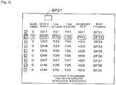
- Display section 74 can list the identification information for identifying corresponding measurement planned position 91 for multiple reference measurement positions 93a, the coordinates of reference measurement position 93a on substrate 90, and the measurement results measured by measurement section 73. For example, after the height of substrate 90 is measured by measurement device 60, the operator operates operation section BP12 illustrated in Fig. 7 . As a result, display section 74 allows display device 50 to display the information illustrated in Fig. 9 in a list.
- Fig. 9 illustrates a display example of the measurement result of the height of substrate 90 measured at measurement position 93 in Fig. 8 .
- a check box In the example illustrated in Fig. 9 , a check box, a board number, the identification information of measurement planned position 91, the coordinates (X-axis coordinates and Y-axis coordinates) of reference measurement position 93a, the measurement result measured by measurement section 73, and the height difference are displayed.
- the check box allows the operator to select the presence or absence of a check using the input device, and displays the measurement result or the like of reference measurement position 93a that is checked.
- the board number is identification information for identifying, in one substrate 90, a multi-chamfered substrate on which multiple substrates 90 smaller than substrate 90 are formed so as to be separable, and identification information is assigned to the entire multi-chamfered substrate and each of multiple substrates 90 included in the multi-chamfered substrates.
- Substrate height measuring device 70 can allow measurement device 60 to measure the height of substrate 90 with respect to the entire multi-chamfered substrate. In addition, substrate height measuring device 70 can allow measurement device 60 to measure the height of substrate 90 for each of multiple substrates 90 included in the multi-chamfered substrate.
- Fig. 9 illustrates that reference measurement positions 93a of X-axis coordinate X31 and Y-axis coordinate Y31 are checked by the operator, the board number is the zero number, and the identification information of corresponding measurement planned position 91 is identification information CH1.
- the measurement result of the height of substrate 90 at reference measurement position 93a is height H31
- the height difference between reference measurement position 93a and eight related measurement positions 93b set around reference measurement position 93a is height difference DF31. The same applies to remaining eight reference measurement positions 93a.
- Display section 74 can also change a display method so as to distinguish between the display of reference measurement position 93a at which the height difference exceeds a predetermined value and the display of reference measurement position 93a at which the height difference is equal to or less than a predetermined value. As a result, the operator can easily grasp reference measurement position 93a at which the height difference exceeds the predetermined value.
- the predetermined value of the height difference can be inputted by the operator, for example, in the input section BP21 illustrated in Fig. 9 .
- the above-mentioned information is surrounded by a rectangle for reference measurement position 93a of X-axis coordinate X32 and Y-axis coordinate Y32, indicating that height difference DF32 exceeds the predetermined value.
- display section 74 can display distinguishably the display of reference measurement position 93a at which the height difference exceeds the predetermined value and the display of reference measurement position 93a at which the height difference is equal to or less than the predetermined value, the display method is not limited.
- display section 74 can change the display method of display device 50 according to at least one of the difference in display colors, the presence or absence of a marker, and the difference in icons.
- display section 74 can display reference measurement position 93a at which the height difference exceeds the predetermined value, using a display color (for example, yellow, red, or the like) that is easy for the operator to pay attention to as compared with the display color for the reference measurement position 93a at which the height difference is equal to or less than the predetermined value.
- a display color for example, yellow, red, or the like
- Display section 74 can also guide the adjustment of reference measurement position 93a at which the height difference exceeds a predetermined value with respect to measurement planned position 91.
- Fig. 9 it is displayed that the adjustment of measurement position 93 is necessary for identification information CH2.
- the operator can easily grasp reference measurement position 93a (in this case, reference measurement position 93a of X-axis coordinate X32 and Y-axis coordinate Y32) at which the height difference exceeds the predetermined value, and can perform the adjustment with respect to measurement planned position 91.
- reference measurement position 93a is adjusted as necessary with respect to measurement planned position 91, so that reference measurement position 93a and related measurement position 93b are set. Then, the height of substrate 90 is measured at set reference measurement position 93a and related measurement position 93b, and reference measurement position 93a is readjusted as necessary for reference measurement position 93a at which the height difference exceeds the predetermined value.
- substrate height measuring device 70 can also set reference measurement position 93a at the same position as measurement planned position 91, and set related measurement position 93b based on reference measurement position 93a.
- substrate height measuring device 70 allows measurement device 60 to measure the height of substrate 90 at reference measurement position 93a and related measurement position 93b that are set at the same position as measurement planned position 91. Then, substrate height measuring device 70 can image substrate 90, reset reference measurement position 93a and related measurement position 93b, re-measure the height of substrate 90, and the like with respect to reference measurement position 93a at which the height difference exceeds the predetermined value.
- the substrate height measuring method includes an imaging step, a setting steps, and a measurement step.
- the imaging step corresponds to control performed by imaging section 71.
- the setting step corresponds to control performed by setting section 72.
- the measurement step corresponds to control performed by measurement section 73.
- the substrate height measuring method may include a display step.
- the display step corresponds to control performed by display section 74.
- substrate height measuring device 70 imaging section 71, setting section 72, and measurement section 73 are provided. Accordingly, substrate height measuring device 70 can allow measurement device 60 to measure the height of substrate 90 by enabling measurement device 60 to adjust measurement position 93 at which the height of substrate 90 is actually measured based on measurement planned position 91 of substrate image 90M displayed on display device 50.
- substrate height measuring device 70 can be similarly applied to the substrate height measuring method.
- imaging device 50: display device, 60: measurement device, 70: substrate height measuring device, 71: imaging section, 72: setting section, 73: measurement section, 74: display section, 90: substrate, 91: measurement planned position, 92: region, 93: measurement position, 93a: reference measurement position, 93b: related measurement position, 94: indicating member, 90M: substrate image, FP0: specific position, P0: component, 900: substrate product
Landscapes
- Engineering & Computer Science (AREA)
- Operations Research (AREA)
- Manufacturing & Machinery (AREA)
- Microelectronics & Electronic Packaging (AREA)
- Physics & Mathematics (AREA)
- General Physics & Mathematics (AREA)
- Quality & Reliability (AREA)
- Computer Vision & Pattern Recognition (AREA)
- Theoretical Computer Science (AREA)
- Supply And Installment Of Electrical Components (AREA)
- Length Measuring Devices By Optical Means (AREA)
Abstract
Description
- The present specification discloses techniques related to a substrate height measuring device and a substrate height measuring method.
-
Patent Literature 1 discloses a method of acquiring substrate height data by excluding abnormality data from measurement data in substrate height measurement such as during teaching operation. Specifically, since a substrate formed of an epoxy or the like is a rigid body, a surface of the substrate is flat when viewed from the extreme point of view. Therefore, a measurement value of the height of the substrate measured by slightly scanning changes a little, but no abrupt change occurs. Therefore, the above-described method described inPatent Literature 1 acquires measurement data at predetermined intervals in a predetermined region while moving a substrate height measurement sensor at a constant speed, and excludes the measurement data as an abnormal value when the measurement data is not included in a predetermined range indicating normal data. - Patent Literature 1:
JP-A-2009-27015 - For example, a circuit forming member such as a wiring pattern, a through hole, and a component is provided on a substrate. In addition, an identification code or the like for identifying a substrate product is attached to the substrate. These members may affect a measurement device when measuring a height of the substrate, thereby reducing measurement accuracy.
- In view of such a circumstance, the present specification discloses a substrate height measuring device and a substrate height measuring method capable of adjusting a measurement position at which a measurement device actually measures a height of a substrate and measuring the height of the substrate.
- The present specification discloses a substrate height measuring device including an imaging section, a setting section, and a measurement section. The imaging section allows an imaging device to image a region of at least a part of a clamped substrate, and the region includes a measurement planned position at which a height of the substrate is to be measured. The setting section allows a display device to display a substrate image imaged by the imaging section and adjusts a measurement position at which the height of the substrate is actually measured based on the measurement planned position of the substrate image displayed on the display device to set the measurement position. The measurement section allows a measurement device to measure the height of the substrate at the measurement position set by the setting section.
- In addition, the present specification discloses a substrate height measuring method including an imaging step, a setting step, and a measurement step. In the imaging step, an imaging device images a region of at least a part of a clamped substrate, and the region includes a measurement planned position at which a height of the substrate is to be measured. In the setting step, a display device displays a substrate image imaged in the imaging step to adjust a measurement position at which the height of the substrate is actually measured based on the measurement planned position of the substrate image displayed on the display device to set the measurement position. In the measurement step, a measurement device measures the height of the substrate at the measurement position set by the setting step.
- According to the substrate height measuring device described above, the imaging section, the setting section, and the measurement section are provided. Therefore, the substrate height measuring device can adjust the measurement position at which the height of the substrate is actually measured based on the measurement planned position of the substrate image displayed on the display device, and thus, can allow the measurement device to measure the height of the substrate. The above description of the substrate height measuring device can be similarly applied to the substrate height measuring method.
-
- [
Fig. 1] Fig. 1 is a plan view illustrating a configuration example of a component mounter. - [
Fig. 2] Fig. 2 is a block diagram illustrating an example of a control block of a substrate height measuring device. - [
Fig. 3] Fig. 3 is a flowchart illustrating an example of a control procedure by the substrate height measuring device. - [
Fig. 4] Fig. 4 is a schematic diagram illustrating an example of a member provided on a substrate. - [
Fig. 5] Fig. 5 is a plan view of a substrate illustrating a setting example of a measurement planned position. - [
Fig. 6] Fig. 6 is a schematic diagram illustrating an example of a substrate image displayed on a display device. - [
Fig. 7] Fig. 7 is a schematic diagram illustrating another example of a substrate image displayed on the display device. - [
Fig. 8] Fig. 8 is a schematic diagram illustrating a setting example of a reference measurement position and a related measurement position. - [
Fig. 9] Fig. 9 is a schematic diagram illustrating a display example of a measurement result of the height of the substrate measured at the measurement position inFig. 8 . - Substrate
height measuring device 70 may be provided in a substrate working machine that needs to measure a height ofclamped substrate 90. For example, a printer, a printing inspection machine,component mounter 10, and an appearance inspector are included in the substrate working machine. Substrateheight measuring device 70 of the present embodiment is provided incomponent mounter 10. Component mounter 10 mounts multiple components P0 onsubstrate 90. As illustrated inFig. 1 ,component mounter 10 includessubstrate conveyance device 11,component supply device 12,component transfer device 13,part camera 14, substrate camera 15, andcontrol device 16. - For example,
substrate conveyance device 11 includes a belt conveyor or the like, and conveyssubstrate 90 in a conveyance direction (X-axis direction).Substrate 90 is a circuit substrate on which an electronic circuit, an electrical circuit, a magnetic circuit, and the like are formed.Substrate conveyance device 11 conveyssubstrate 90 intocomponent mounter 10, and positions andclamps substrate 90 at a predetermined position incomponent mounter 10. After mounting process of multiple components P0 bycomponent mounter 10 is completed,substrate conveyance device 11unclamps substrate 90 and conveyssubstrate 90 to the outside ofcomponent mounter 10. -
Component supply device 12 supplies multiple components P0 to be mounted onsubstrate 90.Component supply device 12 includesmultiple feeders 121 that are provided along the conveyance direction (X-axis direction) ofsubstrate 90. Each ofmultiple feeders 121 pitch-feeds a carrier tape in which multiple components P0 are housed, so as to collectably supply components P0 at a supply position located on a distal end side offeeder 121. Moreover,component supply device 12 can supply a relatively large electronic component (lead component or the like) as compared with a chip component or the like in a state of being disposed on a tray. -
Component transfer device 13 includeshead driving device 131 and movingbody 132.Head driving device 131 is configured to move movingbody 132 in the X-axis direction and the Y-axis direction by a linear motion mechanism. Mountinghead 20 is detachably (exchangeably) provided on movingbody 132 by a clamp member.Mounting head 20 uses at least oneholding member 30 to collect and hold component P0 supplied bycomponent supplying device 12, and mounts component P0 onsubstrate 90 positioned bysubstrate conveyance device 11. For example, holdingmember 30 can use a suction nozzle, a chuck, and the like. - As
part camera 14 and substrate camera 15, a well-known imaging device can be used.Part camera 14 is fixed to a base ofcomponent mounter 10 such that an optical axis faces upward in a vertical direction (Z-axis direction).Part camera 14 can image an image of component P0 held by holdingmember 30 from below. Substrate camera 15 is provided on movingbody 132 ofcomponent transfer device 13 such that the optical axis faces downward in the vertical direction (Z-axis direction). Substrate camera 15 can imagesubstrate 90 from above.Part camera 14 and substrate camera 15 perform imaging based on a control signal transmitted fromcontrol device 16. Image data of the captured image imaged bypart camera 14 and substrate camera 15 is transmitted tocontrol device 16. -
Control device 16 includes a known arithmetic device and a storage device, and constitutes a control circuit. Information, image data, and the like output from various sensors provided incomponent mounter 10 are input to controldevice 16.Control device 16 transmits the control signals to each device based on a control program, a predetermined mounting condition which is set in advance, and the like. - For example,
control device 16 allows substrate camera 15 to imagesubstrate 90 which is positioned bysubstrate conveyance device 11.Control device 16 performs image processing of the captured image imaged by substrate camera 15 to recognize a positioning state ofsubstrate 90. In addition,control device 16 allows holdingmember 30 to collect and hold component P0 supplied bycomponent supplying device 12, andpart camera 14 to image component P0 held by holdingmember 30.Control device 16 performs image processing on the captured image imaged bypart camera 14 to recognize a holding posture of component P0. -
Control device 16moves holding member 30 upwards a mounting planned position set in advance by a control program or the like. In addition,control device 16 corrects the mounting planned position based on the positioning state ofsubstrate 90, the holding posture of component P0, and the like, and sets the mounting position at which component P0 is actually mounted. The mounting planned position and the mounting position include a rotation angle in addition to the position (an X-axis coordinate and a Y-axis coordinate). -
Control device 16 corrects a target position (the X-axis coordinate and the Y-axis coordinate) of holdingmember 30 and the rotation angle according to the mounting position.Control device 16 lowers holdingmember 30 at the corrected rotation angle at the corrected target position, and mounts component P0 onsubstrate 90.Control device 16 executes the mounting process for mounting multiple components P0 onsubstrate 90 by repeating the pick-and-place cycle described above. - Substrate
height measuring device 70 of the present embodiment is provided incontrol device 16 ofcomponent mounter 10. When viewed as a control block, substrateheight measuring device 70 includesimaging section 71, settingsection 72, andmeasurement section 73. Substrateheight measuring device 70 may also includedisplay section 74. As illustrated inFig. 2 , substrateheight measuring device 70 of the present embodiment includesimaging section 71, settingsection 72,measurement section 73, anddisplay section 74. - In addition, substrate
height measuring device 70 of the present embodiment executes control according to a flowchart illustrated inFig. 3 .Imaging section 71 performs processing illustrated in Step S11. Settingsection 72 performs processing illustrated in Step S12.Measurement section 73 performs processing illustrated in Step S13.Display section 74 performs processing illustrated in Step S14. -
Fig. 4 illustrates an example of a member provided on the substrate.Fig. 4 is an enlarged plan view of a portion ofsubstrate 90 clamped bysubstrate conveyance device 11. As illustrated in the drawing, for example, circuit forming members such as wiring pattern WP0, through hole SH0, and component P0 are provided onsubstrate 90. In addition, an identification code or the like for identifyingsubstrate product 900 is attached tosubstrate 90. These members may affectmeasurement device 60 whenmeasurement device 60 measures the height ofsubstrate 90, thereby reducing measurement accuracy. - For example, it is assumed that
measurement device 60 for measuring the height ofsubstrate 90 is an optical measurement device. In this case,measurement device 60 projects laser light onsubstrate 90, receives the laser light reflected bysubstrate 90, and measures the height ofsubstrate 90 by the principle of triangulation. Therefore, in a case where the member is provided in the vicinity of measurement plannedposition 91 where the height ofsubstrate 90 is to be measured, there is a possibility that the laser light is scattered by the member, and thus, the measurement accuracy is reduced. InFig. 4 , a region that may affect the measurement accuracy is indicated by a dashed-line circle. In the drawing, a part of component P0 and wiring pattern WP0 is included in a circle, and the drawing indicates that the measurement accuracy ofmeasurement device 60 may be reduced. - Substrate
height measuring device 70 allowsdisplay device 50 to displaysubstrate image 90M imaged by imagingsection 71. Then, substrateheight measuring device 70 allowsmeasurement device 60 to adjustmeasurement position 93 at which the height ofsubstrate 90 is actually measured based on measurement plannedposition 91 ofsubstrate image 90M displayed ondisplay device 50, so that the height ofsubstrate 90 is measured bymeasurement device 60. Therefore, when a member for reducing the measurement accuracy is provided in the vicinity of measurement plannedposition 91, it is possible to setmeasurement position 93 at a position where the member is avoided. -
Imaging section 71 allowsimaging device 40 to imageregion 92 of at least a part ofsubstrate 90, andregion 92 includes measurement plannedposition 91 at which the height of clampedsubstrate 90 is to be measured (Step S11 illustrated inFig. 3 ). -
Component mounter 10 confirms a state of warpage ofsubstrate 90 based on the measurement result of the height ofsubstrate 90 measured by substrateheight measuring device 70. In addition,component mounter 10 can adjust the height of holdingmember 30 when component P0 is mounted onsubstrate 90 based on the measurement result. Therefore, measurement plannedposition 91 is set so as to be able to confirm the state of warpage ofsubstrate 90 and to adjust the height of holdingmember 30. Measurement plannedposition 91 is set in advance in accordance with a substrate type by a control program or the like. For example, the larger a size ofsubstrate 90, the greater the set number of measurement planned positions 91. In addition, the lower rigidity ofsubstrate 90, the greater the set number of measurement planned positions 91. Further, identification information capable of identifying measurement plannedposition 91 is assigned to multiple measurement planned positions 91. -
Fig. 5 illustrates a setting example of measurement plannedposition 91. In the drawing, one measurement plannedposition 91 is set at the center ofsubstrate 90. In addition, in the drawing, eight measurement plannedpositions 91 are set along an outer edge portion ofsubstrate 90. By setting at least one measurement plannedposition 91 at the center portion ofsubstrate 90 and setting multiple measurement plannedpositions 91 at the outer edge portion ofsubstrate 90,component mounter 10 can easily grasp the state of warpage (concave state or convex state) ofsubstrate 90. - In addition, by setting at least three measurement planned
positions 91 in one side direction (X-axis direction) ofsubstrate 90,component mounter 10 can easily grasp the state of warpage (concave state or convex state) ofsubstrate 90 in one side direction (X-axis direction) ofsubstrate 90. By setting at least three measurement plannedpositions 91 in another side direction (Y-axis direction) ofsubstrate 90,component mounter 10 can easily grasp the state of warpage (concave state or convex state) ofsubstrate 90 in another side direction (Y-axis direction) ofsubstrate 90. By recognizing the state of warpage (concave state or convex state) ofsubstrate 90 in this manner,component mounter 10 can easily adjust the height of holdingmember 30. -
Imaging device 40 can use a known imaging device as long as it can imageregion 92 of at least a part ofsubstrate 90, theregion 92 including measurement plannedposition 91. As illustrated inFig. 1 , substrate camera 15 is used inimaging device 40 of the present embodiment. As illustrated inFig. 5 , substrate camera 15 can imageregion 92 of a part ofsubstrate 90 including measurement plannedposition 91. It should be noted thatcomponent mounter 10 may also include an imaging device capable of imagingentire region 92 ofsubstrate 90. In this case,imaging device 40 can also imageentire region 92 ofsubstrate 90 including measurement plannedposition 91. - Setting
section 72 allowsdisplay device 50 to displaysubstrate image 90M imaged by imagingsection 71 and can adjustmeasurement position 93 at which the height ofsubstrate 90 is actually measured based on measurement plannedposition 91 ofsubstrate image 90M displayed ondisplay device 50 to set measurement position 93 (Step S12 illustrated inFig. 3 ). -
Display device 50 can use any well-known display device as long as it can displaysubstrate image 90M captured by imagingsection 71. As illustrated inFig. 1 ,display device 50 according to the present embodiment uses a display device provided incomponent mounter 10.Display device 50 may be provided separately. -
Fig. 6 illustrates an example ofsubstrate image 90M displayed ondisplay device 50. Insubstrate image 90M inFig. 6 ,region 92 ofsubstrate 90 illustrated inFig. 4 is imaged. Insubstrate image 90M, image feature amounts such as brightness and lightness of a region in which a circuit forming member such as wiring pattern WP0, through hole SH0, and component P0 is imaged are different from those of a region in which the circuit forming member is not imaged. Accordingly, settingsection 72 can adjustmeasurement position 93 based on the image feature amount ofsubstrate image 90M by performing the image processing onsubstrate image 90M. - Specifically, since an image feature amount of a region of a part of a dashed-line circle illustrated in
Fig. 6 differs from an image feature amount of a region in which the circuit forming member is not imaged, settingsection 72 determines that adjustment ofmeasurement position 93 is necessary. Settingsection 72 movesmeasurement position 93 so that the image feature amount of the entire region of the circle is equal to the image feature amount of the region in which the circuit forming member is not imaged. The above description of the circuit forming member also applies to an identification code or the like for identifyingsubstrate product 900. - However, in the above method, for example, the image feature amount may be changed due to imaging conditions of
imaging device 40, disturbance during the imaging, or the like, and thus, the adjustment ofmeasurement position 93 may be difficult. Accordingly, settingsection 72 can set specific position FP0 ofsubstrate image 90M indicated by an operator asmeasurement position 93. In this mode, the operator can adjustmeasurement position 93 while confirmingsubstrate image 90M displayed ondisplay device 50. - The mode in which the operator indicates specific position FP0 is not limited, and may take various forms. For example, setting
section 72 can display coordinate axes (X-axis and Y-axis) onsubstrate image 90M displayed ondisplay device 50, and thus, an operator can input coordinates (X-axis coordinates and Y-axis coordinates) of specific position FP0. In this case, settingsection 72 may display grid-shaped auxiliary lines or the like insubstrate image 90M displayed ondisplay device 50. As a result, it is easy for the operator to acquire the coordinates of specific position FP0. - Setting
section 72 can display indicatingmember 94 in a predetermined region including measurement plannedposition 91 ofsubstrate image 90M displayed ondisplay device 50, allow the operator to move indicatingmember 94 using the input device, and allow the operator to indicate specific position FP0. As a result, the operator can easily indicate specific position FP0. - Indicating
member 94 is an assisting means for the operator to indicate specific position FP0, and may take various forms. Indicatingmember 94 illustrated inFig. 6 is a circular icon, and the center of the circle corresponds to specific position FP0.Display device 50 of the present embodiment includes a touch panel and also serves as an input device for receiving various operations by an operator. The operator can move indicatingmember 94 by touching indicatingmember 94 displayed ondisplay device 50 to indicate specific position FP0. In addition, the operator can use various input devices (for example, a mouse, a keyboard, or the like) provided incomponent mounter 10 to move indicatingmember 94 displayed ondisplay device 50 to indicate specific position FP0. - For example, a shape of indicating
member 94 can be set to coincide with a range that may affect the measurement accuracy ofmeasurement device 60. As a result, the operator can indicate specific position FP0 so that the circuit forming member or the like is not included in the range that may affect the measurement accuracy ofmeasurement device 60. - For example, in a case where the circuit forming member or the like is not included in the range that may affect the measurement accuracy of
measurement device 60,measurement position 93 need not be moved. In this case,measurement position 93 is set to the same position as measurement plannedposition 91 without being adjusted with respect to measurement plannedposition 91. In this manner, makingmeasurement position 93 adjustable includes a case wheremeasurement position 93 is set to be adjusted with respect to measurement plannedposition 91 and a case wheremeasurement position 93 is set at the same position as measurement plannedposition 91 without being adjusted with respect to measurement plannedposition 91. -
Measurement section 73 allowsmeasurement device 60 to measure the height ofsubstrate 90 atmeasurement position 93 set by setting section 72 (Step S13 illustrated inFig. 3 ). -
Measurement device 60 can use any well-known measurement device as long as it can measure the height ofsubstrate 90. Asmeasurement device 60, for example, various measurement devices such as the optical measurement device and the capacitance measurement device described above can be used.Measurement device 60 of the present embodiment is an optical measurement device. As illustrated inFig. 1 ,measurement device 60 of the present embodiment is provided on movingbody 132 ofcomponent transfer device 13 on which substrate camera 15 is provided. -
Measurement section 73 can allowmeasurement device 60 to measure the height ofsubstrate 90 in trial manufacturing ofsubstrate product 900 performed before manufacturingsubstrate product 900 on which component P0 is mounted onsubstrate 90, or in initial product confirmation when the type ofsubstrate product 900 to be manufactured is switched. As a result, the operator or the device (for example, component mounter 10) can confirm a state of warpage ofsubstrate 90 before manufacturingsubstrate product 900, and can also adjust the height of holdingmember 30 when component P0 is mounted onsubstrate 90. - In addition,
measurement section 73 can allowmeasurement device 60 to measure the height ofsubstrate 90 during the manufacturing ofsubstrate product 900. As a result, the operator or the device (for example, component mounter 10) can confirm the state of warpage ofsubstrate 90 during the manufacturing ofsubstrate product 900, and can also adjust the height of holdingmember 30. In addition, as described later, in the trial manufacturing or the initial product confirmation ofsubstrate product 900 and the manufacturing ofsubstrate product 900, the number of measurements for measuring the height ofsubstrate 90 may be changed for the same type ofsubstrate 90. -
Display section 74 allowsdisplay device 50 to display the coordinates ofmeasurement position 93 onsubstrate 90 and the measurement result measured by measurement section 73 (Step S14 illustrated inFig. 3 ). -
Display section 74 may be any section as long as it can display at least the above-mentioned contents ondisplay device 50, and the display method can take various forms. For example, after the height ofsubstrate 90 is measured bymeasurement device 60, the operator operates operation section BP11 illustrated inFig. 6 . As a result,display section 74 allowsdisplay device 50 to display the coordinates (the X-axis coordinate and the Y-axis coordinate) ofmeasurement position 93 onsubstrate 90 and the measurement result measured bymeasurement section 73 together withsubstrate image 90M.Fig. 6 illustrates that the measurement result of the height ofsubstrate 90 atmeasurement position 93 of X-axis coordinate X10 and Y-axis coordinate Y10 is height H10. - In addition,
display section 74 can allowdisplay device 50 to display not only text but also a substrate image or the like indicating the state of warpage ofsubstrate 90. In addition,display section 74 can display the coordinates (X-axis coordinates and Y-axis coordinates) ofmeasurement position 93 onsubstrate 90 whenmeasurement position 93 is adjusted. In this case,display section 74 can display the coordinates (the X-axis coordinate and the Y-axis coordinate) ofmeasurement position 93 onsubstrate 90 in accordance with the movement ofmeasurement position 93. - It may be difficult to grasp a situation around
measurement position 93 based onsubstrate image 90M. For example, unevenness or the like ofsubstrate 90 that is difficult to find based onsubstrate image 90M may exist aroundmeasurement position 93. Whenmeasurement device 60 measures height ofsubstrate 90 in such a region, the measurement accuracy may be reduced. - Accordingly, setting
section 72 can set related measurement position 93b which is at least onemeasurement position 93 around reference measurement position 93a that ismeasurement position 93 adjusted and set with respect to measurement plannedposition 91, ormeasurement position 93 set without being adjusted with respect to measurement plannedposition 91. As a result, the operator or the device (for example, component mounter 10) can grasp the situation in the vicinity of reference measurement position 93a, and can movemeasurement position 93 as required. -
Fig. 7 illustrates another example ofsubstrate image 90M displayed ondisplay device 50.Fig. 7 illustrates that eight related measurement positions 93b are set around reference measurement position 93a of X-axis coordinate X10 and Y-axis coordinate Y10. Measurement plannedposition 91 and reference measurement position 93a are indicated by black circles, and eight related measurement positions 93b are indicated by white circles. As illustrated inFig. 7 , reference measurement position 93a of X-axis coordinate X10 and Y-axis coordinate Y10 ismeasurement position 93 adjusted and set with respect to measurement plannedposition 91. - As described above,
measurement position 93 may be set at the same position as measurement plannedposition 91 without being adjusted with respect to measurement plannedposition 91. Also in this case, settingsection 72 can set at least one related measurement position 93b around reference measurement position 93a. - In addition, disposition of reference measurement position 93a and related measurement position 93b is not limited, but reference measurement position 93a and related measurement position 93b may be disposed on lattice points. As a result, it is easy to uniformly dispose related measurement positions 93b. In the example illustrated in
Fig. 7 , reference measurement position 93a and eight related measurement positions 93b are disposed on lattice points. - Also in this mode,
display section 74 can allowdisplay device 50 to display the coordinates ofmeasurement position 93 onsubstrate 90 and the measurement result measured bymeasurement section 73. For example, after the height ofsubstrate 90 is measured bymeasurement device 60, the operator operates operation section BP11 illustrated inFig. 7 . As a result,display section 74 allowsdisplay device 50 to display the coordinates (the X-axis coordinate and the Y-axis coordinate) ofsubstrate 90 and the measurement result measured bymeasurement section 73 for reference measurement position 93a and eight related measurement positions 93b together withsubstrate image 90M. -
Fig. 7 illustrates that the measurement result of the height ofsubstrate 90 at reference measurement position 93a of X-axis coordinate X10 and Y-axis coordinate Y10 is height H10. In addition,Fig. 7 illustrates that the measurement result of the height ofsubstrate 90 at related measurement position 93b of X-axis coordinate X1 and Y-axis coordinate Y1 is height H11. What has been described above for the related measurement position 93b is the same for the remaining seven related measurement positions 93b. -
Display section 74 may further display a height difference obtained by subtracting the minimum value from the maximum value of the measurement result of reference measurement position 93a and related measurement position 93b measured bymeasurement section 73. As a result, the operator can easily recognize the height difference, and can grasp the situation around reference measurement position 93a based on the height difference.Fig. 7 illustrates that the height difference with respect to the measurement results of reference measurement position 93a and eight related measurement positions 93b is height difference DF10. - It should be noted that in the manufacturing of
substrate product 900, when the height ofsubstrate 90 is measured bymeasurement device 60 with respect to both reference measurement position 93a and related measurement position 93b, a measurement time may increase, and a measurement operation may also be complicated. Therefore,measurement section 73 may allowmeasurement device 60 to measure the height ofsubstrate 90 for both reference measurement position 93a and related measurement position 93b in the trial manufacturing or the initial product confirmation ofsubstrate product 900. - In addition, in the manufacturing of
substrate product 900,measurement section 73 may allow measurement of the height ofsubstrate 90 at reference measurement position 93a, and restrict the measurement of the height ofsubstrate 90 at related measurement position 93b. As described above, in the trial manufacturing or the initial product confirmation ofsubstrate product 900 and the manufacturing ofsubstrate product 900, the number of measurements for measuring the height ofsubstrate 90 can be changed for the same type ofsubstrate 90. - As described above,
substrate 90 may be provided with multiple measurement planned positions 91. Settingsection 72 can set, for each of multiple measurement plannedpositions 91, related measurement position 93b which is at least onemeasurement position 93 around reference measurement position 93a that ismeasurement position 93 adjusted and set with respect to measurement plannedposition 91, ormeasurement position 93 set without being adjusted with respect to measurement plannedposition 91. -
Fig. 8 illustrates a setting example of reference measurement position 93a and related measurement position 93b.Fig. 8 illustrates an example of a state in which reference measurement position 93a and eight related measurement positions 93b are set for each of nine measurement plannedpositions 91 illustrated inFig. 5 . Six reference measurement positions 93a of nine reference measurement positions 93a are adjusted and set with respect to measurement plannedposition 91. Three reference measurement positions 93a of nine reference measurement positions 93a are set without being adjusted with respect to measurement plannedposition 91. -
Display section 74 can list the identification information for identifying corresponding measurement plannedposition 91 for multiple reference measurement positions 93a, the coordinates of reference measurement position 93a onsubstrate 90, and the measurement results measured bymeasurement section 73. For example, after the height ofsubstrate 90 is measured bymeasurement device 60, the operator operates operation section BP12 illustrated inFig. 7 . As a result,display section 74 allowsdisplay device 50 to display the information illustrated inFig. 9 in a list.Fig. 9 illustrates a display example of the measurement result of the height ofsubstrate 90 measured atmeasurement position 93 inFig. 8 . - In the example illustrated in
Fig. 9 , a check box, a board number, the identification information of measurement plannedposition 91, the coordinates (X-axis coordinates and Y-axis coordinates) of reference measurement position 93a, the measurement result measured bymeasurement section 73, and the height difference are displayed. The check box allows the operator to select the presence or absence of a check using the input device, and displays the measurement result or the like of reference measurement position 93a that is checked. - The board number is identification information for identifying, in one
substrate 90, a multi-chamfered substrate on whichmultiple substrates 90 smaller thansubstrate 90 are formed so as to be separable, and identification information is assigned to the entire multi-chamfered substrate and each ofmultiple substrates 90 included in the multi-chamfered substrates. Substrateheight measuring device 70 can allowmeasurement device 60 to measure the height ofsubstrate 90 with respect to the entire multi-chamfered substrate. In addition, substrateheight measuring device 70 can allowmeasurement device 60 to measure the height ofsubstrate 90 for each ofmultiple substrates 90 included in the multi-chamfered substrate. -
Fig. 9 illustrates that reference measurement positions 93a of X-axis coordinate X31 and Y-axis coordinate Y31 are checked by the operator, the board number is the zero number, and the identification information of corresponding measurement plannedposition 91 is identification information CH1. In addition, it is indicated that the measurement result of the height ofsubstrate 90 at reference measurement position 93a is height H31, and the height difference between reference measurement position 93a and eight related measurement positions 93b set around reference measurement position 93a is height difference DF31. The same applies to remaining eight reference measurement positions 93a. -
Display section 74 can also change a display method so as to distinguish between the display of reference measurement position 93a at which the height difference exceeds a predetermined value and the display of reference measurement position 93a at which the height difference is equal to or less than a predetermined value. As a result, the operator can easily grasp reference measurement position 93a at which the height difference exceeds the predetermined value. The predetermined value of the height difference can be inputted by the operator, for example, in the input section BP21 illustrated inFig. 9 . InFig. 9 , the above-mentioned information is surrounded by a rectangle for reference measurement position 93a of X-axis coordinate X32 and Y-axis coordinate Y32, indicating that height difference DF32 exceeds the predetermined value. - As long as
display section 74 can display distinguishably the display of reference measurement position 93a at which the height difference exceeds the predetermined value and the display of reference measurement position 93a at which the height difference is equal to or less than the predetermined value, the display method is not limited. For example,display section 74 can change the display method ofdisplay device 50 according to at least one of the difference in display colors, the presence or absence of a marker, and the difference in icons. - For example,
display section 74 can display reference measurement position 93a at which the height difference exceeds the predetermined value, using a display color (for example, yellow, red, or the like) that is easy for the operator to pay attention to as compared with the display color for the reference measurement position 93a at which the height difference is equal to or less than the predetermined value. The same applies to the marker and the icon, and may take various forms such as a display color, a form, a movement in a display screen, and a blinking display that can be easily noticed by an operator. -
Display section 74 can also guide the adjustment of reference measurement position 93a at which the height difference exceeds a predetermined value with respect to measurement plannedposition 91. InFig. 9 , it is displayed that the adjustment ofmeasurement position 93 is necessary for identification information CH2. As a result, the operator can easily grasp reference measurement position 93a (in this case, reference measurement position 93a of X-axis coordinate X32 and Y-axis coordinate Y32) at which the height difference exceeds the predetermined value, and can perform the adjustment with respect to measurement plannedposition 91. - In the above-described embodiment, reference measurement position 93a is adjusted as necessary with respect to measurement planned
position 91, so that reference measurement position 93a and related measurement position 93b are set. Then, the height ofsubstrate 90 is measured at set reference measurement position 93a and related measurement position 93b, and reference measurement position 93a is readjusted as necessary for reference measurement position 93a at which the height difference exceeds the predetermined value. - However, substrate
height measuring device 70 can also set reference measurement position 93a at the same position as measurement plannedposition 91, and set related measurement position 93b based on reference measurement position 93a. In this case, substrateheight measuring device 70 allowsmeasurement device 60 to measure the height ofsubstrate 90 at reference measurement position 93a and related measurement position 93b that are set at the same position as measurement plannedposition 91. Then, substrateheight measuring device 70 can imagesubstrate 90, reset reference measurement position 93a and related measurement position 93b, re-measure the height ofsubstrate 90, and the like with respect to reference measurement position 93a at which the height difference exceeds the predetermined value. - The above description of substrate
height measuring device 70 can be similarly applied to a substrate height measuring method. Specifically, the substrate height measuring method includes an imaging step, a setting steps, and a measurement step. The imaging step corresponds to control performed byimaging section 71. The setting step corresponds to control performed by settingsection 72. The measurement step corresponds to control performed bymeasurement section 73. In addition, the substrate height measuring method may include a display step. The display step corresponds to control performed bydisplay section 74. - According to substrate
height measuring device 70,imaging section 71, settingsection 72, andmeasurement section 73 are provided. Accordingly, substrateheight measuring device 70 can allowmeasurement device 60 to measure the height ofsubstrate 90 by enablingmeasurement device 60 to adjustmeasurement position 93 at which the height ofsubstrate 90 is actually measured based on measurement plannedposition 91 ofsubstrate image 90M displayed ondisplay device 50. The above description of substrateheight measuring device 70 can be similarly applied to the substrate height measuring method. - 40: imaging device, 50: display device, 60: measurement device, 70: substrate height measuring device, 71: imaging section, 72: setting section, 73: measurement section, 74: display section, 90: substrate, 91: measurement planned position, 92: region, 93: measurement position, 93a: reference measurement position, 93b: related measurement position, 94: indicating member, 90M: substrate image, FP0: specific position, P0: component, 900: substrate product
Claims (12)
- A substrate height measuring device comprising:an imaging section configured to allow an imaging device to image a region of at least a part of a clamped substrate, the region including a measurement planned position at which a height of the substrate is to be measured;a setting section configured to allow a display device to display a substrate image imaged by the imaging section and adjust a measurement position at which the height of the substrate is actually measured based on the measurement planned position of the substrate image displayed on the display device to set the measurement position; anda measurement section configured to allow a measurement device to measure the height of the substrate at the measurement position set by the setting section.
- The substrate height measuring device according to Claim 1,
wherein the setting section sets a specific position of the substrate image indicated by an operator as the measurement position. - The substrate height measuring device according to Claim 2,
wherein the setting section allows an indicating member to be displayed in a predetermined region including the measurement planned position of the substrate image displayed on the display device, and the operator to move the indicating member using an input device to allow the operator to indicate the specific position. - The substrate height measuring device according to any one of Claims 1 to 3,
wherein the setting section sets a related measurement position which is at least one measurement position around a reference measurement position that is the measurement position adjusted and set with respect to the measurement planned position, or the measurement position set without being adjusted with respect to the measurement planned position. - The substrate height measuring device according to Claim 4,
wherein the reference measurement position and the related measurement position are disposed on lattice points. - The substrate height measuring device according to any one of Claims 1 to 5,
wherein the measurement section measures the height of the substrate in trial manufacturing of a substrate product in which a component is mounted on the substrate performed before manufacturing the substrate product or in initial product confirmation when a type of the substrate product to be manufactured is switched. - The substrate height measuring device according to any one of Claims 1 to 6, further comprising:
a display section configured to display coordinates of the measurement position on the substrate and measurement results measured by the measurement section on the display device. - The substrate height measuring device according to Claim 7,wherein multiple measurement planned positions are provided on the substrate,the setting section sets, for each of the multiple measurement planned positions, a related measurement position which is at least one measurement position around a reference measurement position that is the measurement position adjusted and set with respect to the measurement planned position, or the measurement position set without being adjusted with respect to the measurement planned position, andthe display section lists identification information for identifying corresponding measurement planned positions for multiple reference measurement positions, coordinates of the reference measurement position on the substrate, and a measurement result measured by the measurement section.
- The substrate height measuring device according to Claim 7 or 8,wherein the setting section sets a related measurement position which is at least one measurement position around a reference measurement position that is the measurement position adjusted and set with respect to the measurement planned position, or the measurement position set without being adjusted with respect to the measurement planned position, andthe display section further displays a height difference obtained by subtracting a minimum value from a maximum value of measurement results of the reference measurement position and the related measurement position measured by the measurement section.
- The substrate height measuring device according to Claim 9,
wherein the display section changes a display method so as to distinguish between display of the reference measurement position at which the height difference exceeds a predetermined value and display of the reference measurement position at which the height difference is equal to or less than the predetermined value. - The substrate height measuring device according to Claim 9 or 10,
wherein the display section guides adjustment of the reference measurement position at which the height difference exceeds a predetermined value with respect to the measurement planned position. - A substrate height measuring method comprising:an imaging step of allowing an imaging device to image a region of at least a part of a clamped substrate, the region including a measurement planned position at which a height of the substrate is to be measured;a setting step of allowing a display device to display a substrate image imaged in the imaging step and adjusting a measurement position at which the height of the substrate is actually measured based on the measurement planned position of the substrate image displayed on the display device to set the measurement position; anda measurement step of allowing a measurement device to measure the height of the substrate at the measurement position set by the setting step.
Applications Claiming Priority (1)
| Application Number | Priority Date | Filing Date | Title |
|---|---|---|---|
| PCT/JP2020/010489 WO2021181556A1 (en) | 2020-03-11 | 2020-03-11 | Substrate height measuring device and substrate height measuring method |
Publications (3)
| Publication Number | Publication Date |
|---|---|
| EP4120814A1 true EP4120814A1 (en) | 2023-01-18 |
| EP4120814A4 EP4120814A4 (en) | 2023-03-15 |
| EP4120814B1 EP4120814B1 (en) | 2024-10-30 |
Family
ID=77671329
Family Applications (1)
| Application Number | Title | Priority Date | Filing Date |
|---|---|---|---|
| EP20924283.3A Active EP4120814B1 (en) | 2020-03-11 | 2020-03-11 | Substrate height measuring device and substrate height measuring method |
Country Status (5)
| Country | Link |
|---|---|
| US (1) | US20230121221A1 (en) |
| EP (1) | EP4120814B1 (en) |
| JP (1) | JP7280431B2 (en) |
| CN (1) | CN115669253A (en) |
| WO (1) | WO2021181556A1 (en) |
Families Citing this family (4)
| Publication number | Priority date | Publication date | Assignee | Title |
|---|---|---|---|---|
| WO2023145091A1 (en) * | 2022-01-31 | 2023-08-03 | ヤマハファインテック株式会社 | Processing apparatus and processing method |
| JP7857594B2 (en) * | 2022-03-30 | 2026-05-13 | パナソニックIpマネジメント株式会社 | Mounting machine and method for measuring board height |
| CN116989684A (en) * | 2023-09-27 | 2023-11-03 | 广州镭晨智能装备科技有限公司 | Floating height detection device, detection system and detection method |
| WO2025079185A1 (en) * | 2023-10-11 | 2025-04-17 | 株式会社Fuji | Mounting machine, substrate height measurement position determination device, and substrate height measurement position determination method |
Family Cites Families (19)
| Publication number | Priority date | Publication date | Assignee | Title |
|---|---|---|---|---|
| JP3335826B2 (en) * | 1995-12-05 | 2002-10-21 | 株式会社日立製作所 | Solder bump measuring device |
| JP4353100B2 (en) * | 2005-01-21 | 2009-10-28 | パナソニック株式会社 | Electronic component mounting system and electronic component mounting method |
| JP4185960B2 (en) * | 2005-11-29 | 2008-11-26 | 松下電器産業株式会社 | Working device and working method for circuit board |
| JP4887205B2 (en) | 2007-04-26 | 2012-02-29 | 株式会社日立ハイテクインスツルメンツ | Electronic component mounting method and electronic component mounting apparatus |
| JP4912246B2 (en) | 2007-07-20 | 2012-04-11 | 株式会社日立ハイテクインスツルメンツ | Electronic component mounting method and electronic component mounting apparatus |
| JP2009259984A (en) * | 2008-04-15 | 2009-11-05 | Hitachi High-Tech Instruments Co Ltd | Electronic component mounting apparatus and method of mounting electronic component |
| JP5409502B2 (en) | 2010-04-28 | 2014-02-05 | 株式会社日立ハイテクインスツルメンツ | Electronic component mounting apparatus, electronic component mounting method, and board height data editing apparatus |
| JP2014017328A (en) * | 2012-07-06 | 2014-01-30 | Tdk Corp | Mounting device and measuring method |
| WO2014033856A1 (en) * | 2012-08-29 | 2014-03-06 | 富士機械製造株式会社 | Method for correcting height of substrate for substrate working device |
| US9319593B2 (en) * | 2012-12-10 | 2016-04-19 | Samsung Electronics Co., Ltd. | Recognition apparatus, recognition method, mounting apparatus, and mounting method |
| JP6154143B2 (en) * | 2013-01-25 | 2017-06-28 | Juki株式会社 | Electronic component mounting apparatus and electronic component mounting method |
| JP6432044B2 (en) * | 2015-05-18 | 2018-12-05 | パナソニックIpマネジメント株式会社 | Method for correcting measurement position of height sensor in component mounting apparatus and component mounting apparatus |
| JP6804905B2 (en) * | 2016-09-09 | 2020-12-23 | ヤマハ発動機株式会社 | Board work equipment |
| JP6859098B2 (en) * | 2016-12-28 | 2021-04-14 | 株式会社キーエンス | Optical scanning height measuring device |
| US11324151B2 (en) | 2017-05-24 | 2022-05-03 | Fuji Corporation | Measurement position determination device |
| JP6982984B2 (en) | 2017-05-26 | 2021-12-17 | 株式会社Fuji | Anti-board work equipment |
| JP6928527B2 (en) * | 2017-10-03 | 2021-09-01 | ヤマハ発動機株式会社 | Height measuring device, height measuring method and board work device |
| US11342211B2 (en) * | 2018-05-30 | 2022-05-24 | Hitachi High-Tech Corporation | Wafer inspection apparatus and wafer inspection method |
| JP7333744B2 (en) * | 2019-12-03 | 2023-08-25 | 株式会社ミツトヨ | Height measuring method and height measuring device |
-
2020
- 2020-03-11 US US17/905,380 patent/US20230121221A1/en not_active Abandoned
- 2020-03-11 WO PCT/JP2020/010489 patent/WO2021181556A1/en not_active Ceased
- 2020-03-11 CN CN202080097865.8A patent/CN115669253A/en active Pending
- 2020-03-11 EP EP20924283.3A patent/EP4120814B1/en active Active
- 2020-03-11 JP JP2022507073A patent/JP7280431B2/en active Active
Also Published As
| Publication number | Publication date |
|---|---|
| JP7280431B2 (en) | 2023-05-23 |
| WO2021181556A1 (en) | 2021-09-16 |
| US20230121221A1 (en) | 2023-04-20 |
| EP4120814A4 (en) | 2023-03-15 |
| JPWO2021181556A1 (en) | 2021-09-16 |
| CN115669253A (en) | 2023-01-31 |
| EP4120814B1 (en) | 2024-10-30 |
Similar Documents
| Publication | Publication Date | Title |
|---|---|---|
| EP4120814B1 (en) | Substrate height measuring device and substrate height measuring method | |
| KR102399836B1 (en) | Die bonding apparatus and manufacturing method of semiconductor device | |
| KR102506283B1 (en) | Die bonding apparatus and manufacturing method of semiconductor apparatus | |
| EP3021654B1 (en) | Component holding state detection method and component mounting machine | |
| WO2015025403A1 (en) | Substrate production work method, substrate imaging condition determination method, and substrate production work device | |
| JP2015135886A (en) | Management device | |
| KR20030065414A (en) | Method of locating and placing eye point features of semiconductor die on a substrate | |
| JP2013222740A (en) | Visual inspection device and visual inspection method | |
| JP2013221767A (en) | Visual inspection device and visual inspection method | |
| US20190357397A1 (en) | Coordinate data generation device and coordinate data generation method | |
| US11751370B2 (en) | Correction amount calculation device, component mounting machine, and correction amount calculation method | |
| JP2013221766A (en) | Visual inspection device and visual inspection method | |
| CN101442899B (en) | Component mounting method and apparatus | |
| JP2024015380A (en) | Adsorption position adjustment device | |
| JP5830652B2 (en) | Calibration jig and calibration method for visual inspection | |
| US11653485B2 (en) | Component mounting device | |
| EP3937598A1 (en) | Correction amount calculating device and correction amount calculating method | |
| CN111656884B (en) | Installation device, information processing device, and installation method | |
| WO2021234848A1 (en) | Component mounting system | |
| JP7585051B2 (en) | Imaging device and substrate processing device | |
| JP7594111B2 (en) | Component mounting machine and calibration process control method | |
| JPH03165600A (en) | Mounting device for tape substrate | |
| JP2026510745A (en) | Cross-command vision positioning system and method | |
| US12328825B2 (en) | Analysis device for a component mounting device to analyze board contact of a component | |
| JP2000341000A (en) | Method and jig for evaluating mounting precision of electronic packaged components |
Legal Events
| Date | Code | Title | Description |
|---|---|---|---|
| STAA | Information on the status of an ep patent application or granted ep patent |
Free format text: STATUS: THE INTERNATIONAL PUBLICATION HAS BEEN MADE |
|
| PUAI | Public reference made under article 153(3) epc to a published international application that has entered the european phase |
Free format text: ORIGINAL CODE: 0009012 |
|
| STAA | Information on the status of an ep patent application or granted ep patent |
Free format text: STATUS: REQUEST FOR EXAMINATION WAS MADE |
|
| 17P | Request for examination filed |
Effective date: 20220907 |
|
| AK | Designated contracting states |
Kind code of ref document: A1 Designated state(s): AL AT BE BG CH CY CZ DE DK EE ES FI FR GB GR HR HU IE IS IT LI LT LU LV MC MK MT NL NO PL PT RO RS SE SI SK SM TR |
|
| REG | Reference to a national code |
Ref country code: DE Free format text: PREVIOUS MAIN CLASS: H05K0013040000 Ref country code: DE Ref legal event code: R079 Ref document number: 602020040596 Country of ref document: DE Free format text: PREVIOUS MAIN CLASS: H05K0013040000 Ipc: H05K0013080000 |
|
| A4 | Supplementary search report drawn up and despatched |
Effective date: 20230214 |
|
| RIC1 | Information provided on ipc code assigned before grant |
Ipc: H05K 13/08 20060101AFI20230208BHEP |
|
| DAV | Request for validation of the european patent (deleted) | ||
| DAX | Request for extension of the european patent (deleted) | ||
| P01 | Opt-out of the competence of the unified patent court (upc) registered |
Effective date: 20230328 |
|
| STAA | Information on the status of an ep patent application or granted ep patent |
Free format text: STATUS: EXAMINATION IS IN PROGRESS |
|
| 17Q | First examination report despatched |
Effective date: 20230920 |
|
| GRAP | Despatch of communication of intention to grant a patent |
Free format text: ORIGINAL CODE: EPIDOSNIGR1 |
|
| STAA | Information on the status of an ep patent application or granted ep patent |
Free format text: STATUS: GRANT OF PATENT IS INTENDED |
|
| INTG | Intention to grant announced |
Effective date: 20240701 |
|
| GRAS | Grant fee paid |
Free format text: ORIGINAL CODE: EPIDOSNIGR3 |
|
| GRAA | (expected) grant |
Free format text: ORIGINAL CODE: 0009210 |
|
| STAA | Information on the status of an ep patent application or granted ep patent |
Free format text: STATUS: THE PATENT HAS BEEN GRANTED |
|
| AK | Designated contracting states |
Kind code of ref document: B1 Designated state(s): AL AT BE BG CH CY CZ DE DK EE ES FI FR GB GR HR HU IE IS IT LI LT LU LV MC MK MT NL NO PL PT RO RS SE SI SK SM TR |
|
| REG | Reference to a national code |
Ref country code: GB Ref legal event code: FG4D |
|
| REG | Reference to a national code |
Ref country code: CH Ref legal event code: EP |
|
| REG | Reference to a national code |
Ref country code: IE Ref legal event code: FG4D |
|
| REG | Reference to a national code |
Ref country code: DE Ref legal event code: R096 Ref document number: 602020040596 Country of ref document: DE |
|
| REG | Reference to a national code |
Ref country code: LT Ref legal event code: MG9D |
|
| REG | Reference to a national code |
Ref country code: NL Ref legal event code: MP Effective date: 20241030 |
|
| PG25 | Lapsed in a contracting state [announced via postgrant information from national office to epo] |
Ref country code: HR Free format text: LAPSE BECAUSE OF FAILURE TO SUBMIT A TRANSLATION OF THE DESCRIPTION OR TO PAY THE FEE WITHIN THE PRESCRIBED TIME-LIMIT Effective date: 20241030 Ref country code: PT Free format text: LAPSE BECAUSE OF FAILURE TO SUBMIT A TRANSLATION OF THE DESCRIPTION OR TO PAY THE FEE WITHIN THE PRESCRIBED TIME-LIMIT Effective date: 20250228 Ref country code: IS Free format text: LAPSE BECAUSE OF FAILURE TO SUBMIT A TRANSLATION OF THE DESCRIPTION OR TO PAY THE FEE WITHIN THE PRESCRIBED TIME-LIMIT Effective date: 20250228 |
|
| PG25 | Lapsed in a contracting state [announced via postgrant information from national office to epo] |
Ref country code: FI Free format text: LAPSE BECAUSE OF FAILURE TO SUBMIT A TRANSLATION OF THE DESCRIPTION OR TO PAY THE FEE WITHIN THE PRESCRIBED TIME-LIMIT Effective date: 20241030 Ref country code: NL Free format text: LAPSE BECAUSE OF FAILURE TO SUBMIT A TRANSLATION OF THE DESCRIPTION OR TO PAY THE FEE WITHIN THE PRESCRIBED TIME-LIMIT Effective date: 20241030 |
|
| REG | Reference to a national code |
Ref country code: AT Ref legal event code: MK05 Ref document number: 1738239 Country of ref document: AT Kind code of ref document: T Effective date: 20241030 |
|
| PG25 | Lapsed in a contracting state [announced via postgrant information from national office to epo] |
Ref country code: BG Free format text: LAPSE BECAUSE OF FAILURE TO SUBMIT A TRANSLATION OF THE DESCRIPTION OR TO PAY THE FEE WITHIN THE PRESCRIBED TIME-LIMIT Effective date: 20241030 |
|
| PG25 | Lapsed in a contracting state [announced via postgrant information from national office to epo] |
Ref country code: ES Free format text: LAPSE BECAUSE OF FAILURE TO SUBMIT A TRANSLATION OF THE DESCRIPTION OR TO PAY THE FEE WITHIN THE PRESCRIBED TIME-LIMIT Effective date: 20241030 |
|
| PG25 | Lapsed in a contracting state [announced via postgrant information from national office to epo] |
Ref country code: NO Free format text: LAPSE BECAUSE OF FAILURE TO SUBMIT A TRANSLATION OF THE DESCRIPTION OR TO PAY THE FEE WITHIN THE PRESCRIBED TIME-LIMIT Effective date: 20250130 |
|
| PG25 | Lapsed in a contracting state [announced via postgrant information from national office to epo] |
Ref country code: AT Free format text: LAPSE BECAUSE OF FAILURE TO SUBMIT A TRANSLATION OF THE DESCRIPTION OR TO PAY THE FEE WITHIN THE PRESCRIBED TIME-LIMIT Effective date: 20241030 Ref country code: GR Free format text: LAPSE BECAUSE OF FAILURE TO SUBMIT A TRANSLATION OF THE DESCRIPTION OR TO PAY THE FEE WITHIN THE PRESCRIBED TIME-LIMIT Effective date: 20250131 Ref country code: LV Free format text: LAPSE BECAUSE OF FAILURE TO SUBMIT A TRANSLATION OF THE DESCRIPTION OR TO PAY THE FEE WITHIN THE PRESCRIBED TIME-LIMIT Effective date: 20241030 |
|
| PG25 | Lapsed in a contracting state [announced via postgrant information from national office to epo] |
Ref country code: PL Free format text: LAPSE BECAUSE OF FAILURE TO SUBMIT A TRANSLATION OF THE DESCRIPTION OR TO PAY THE FEE WITHIN THE PRESCRIBED TIME-LIMIT Effective date: 20241030 |
|
| PG25 | Lapsed in a contracting state [announced via postgrant information from national office to epo] |
Ref country code: RS Free format text: LAPSE BECAUSE OF FAILURE TO SUBMIT A TRANSLATION OF THE DESCRIPTION OR TO PAY THE FEE WITHIN THE PRESCRIBED TIME-LIMIT Effective date: 20250130 |
|
| PG25 | Lapsed in a contracting state [announced via postgrant information from national office to epo] |
Ref country code: SM Free format text: LAPSE BECAUSE OF FAILURE TO SUBMIT A TRANSLATION OF THE DESCRIPTION OR TO PAY THE FEE WITHIN THE PRESCRIBED TIME-LIMIT Effective date: 20241030 |
|
| PG25 | Lapsed in a contracting state [announced via postgrant information from national office to epo] |
Ref country code: DK Free format text: LAPSE BECAUSE OF FAILURE TO SUBMIT A TRANSLATION OF THE DESCRIPTION OR TO PAY THE FEE WITHIN THE PRESCRIBED TIME-LIMIT Effective date: 20241030 |
|
| PG25 | Lapsed in a contracting state [announced via postgrant information from national office to epo] |
Ref country code: EE Free format text: LAPSE BECAUSE OF FAILURE TO SUBMIT A TRANSLATION OF THE DESCRIPTION OR TO PAY THE FEE WITHIN THE PRESCRIBED TIME-LIMIT Effective date: 20241030 |
|
| PG25 | Lapsed in a contracting state [announced via postgrant information from national office to epo] |
Ref country code: RO Free format text: LAPSE BECAUSE OF FAILURE TO SUBMIT A TRANSLATION OF THE DESCRIPTION OR TO PAY THE FEE WITHIN THE PRESCRIBED TIME-LIMIT Effective date: 20241030 |
|
| PG25 | Lapsed in a contracting state [announced via postgrant information from national office to epo] |
Ref country code: SK Free format text: LAPSE BECAUSE OF FAILURE TO SUBMIT A TRANSLATION OF THE DESCRIPTION OR TO PAY THE FEE WITHIN THE PRESCRIBED TIME-LIMIT Effective date: 20241030 |
|
| PG25 | Lapsed in a contracting state [announced via postgrant information from national office to epo] |
Ref country code: CZ Free format text: LAPSE BECAUSE OF FAILURE TO SUBMIT A TRANSLATION OF THE DESCRIPTION OR TO PAY THE FEE WITHIN THE PRESCRIBED TIME-LIMIT Effective date: 20241030 |
|
| PG25 | Lapsed in a contracting state [announced via postgrant information from national office to epo] |
Ref country code: IT Free format text: LAPSE BECAUSE OF FAILURE TO SUBMIT A TRANSLATION OF THE DESCRIPTION OR TO PAY THE FEE WITHIN THE PRESCRIBED TIME-LIMIT Effective date: 20241030 |
|
| REG | Reference to a national code |
Ref country code: DE Ref legal event code: R097 Ref document number: 602020040596 Country of ref document: DE |
|
| PLBE | No opposition filed within time limit |
Free format text: ORIGINAL CODE: 0009261 |
|
| STAA | Information on the status of an ep patent application or granted ep patent |
Free format text: STATUS: NO OPPOSITION FILED WITHIN TIME LIMIT |
|
| PG25 | Lapsed in a contracting state [announced via postgrant information from national office to epo] |
Ref country code: SE Free format text: LAPSE BECAUSE OF FAILURE TO SUBMIT A TRANSLATION OF THE DESCRIPTION OR TO PAY THE FEE WITHIN THE PRESCRIBED TIME-LIMIT Effective date: 20241030 |
|
| 26N | No opposition filed |
Effective date: 20250731 |
|
| PG25 | Lapsed in a contracting state [announced via postgrant information from national office to epo] |
Ref country code: MC Free format text: LAPSE BECAUSE OF FAILURE TO SUBMIT A TRANSLATION OF THE DESCRIPTION OR TO PAY THE FEE WITHIN THE PRESCRIBED TIME-LIMIT Effective date: 20241030 |
|
| REG | Reference to a national code |
Ref country code: CH Ref legal event code: H13 Free format text: ST27 STATUS EVENT CODE: U-0-0-H10-H13 (AS PROVIDED BY THE NATIONAL OFFICE) Effective date: 20251023 |
|
| PG25 | Lapsed in a contracting state [announced via postgrant information from national office to epo] |
Ref country code: LU Free format text: LAPSE BECAUSE OF NON-PAYMENT OF DUE FEES Effective date: 20250311 |
|
| GBPC | Gb: european patent ceased through non-payment of renewal fee |
Effective date: 20250311 |
|
| REG | Reference to a national code |
Ref country code: BE Ref legal event code: MM Effective date: 20250331 |
|
| PG25 | Lapsed in a contracting state [announced via postgrant information from national office to epo] |
Ref country code: GB Free format text: LAPSE BECAUSE OF NON-PAYMENT OF DUE FEES Effective date: 20250311 |
|
| PG25 | Lapsed in a contracting state [announced via postgrant information from national office to epo] |
Ref country code: FR Free format text: LAPSE BECAUSE OF NON-PAYMENT OF DUE FEES Effective date: 20250331 |
|
| PG25 | Lapsed in a contracting state [announced via postgrant information from national office to epo] |
Ref country code: BE Free format text: LAPSE BECAUSE OF NON-PAYMENT OF DUE FEES Effective date: 20250331 |
|
| PG25 | Lapsed in a contracting state [announced via postgrant information from national office to epo] |
Ref country code: CH Free format text: LAPSE BECAUSE OF NON-PAYMENT OF DUE FEES Effective date: 20250331 |
|
| PG25 | Lapsed in a contracting state [announced via postgrant information from national office to epo] |
Ref country code: IE Free format text: LAPSE BECAUSE OF NON-PAYMENT OF DUE FEES Effective date: 20250311 |
|
| PGFP | Annual fee paid to national office [announced via postgrant information from national office to epo] |
Ref country code: DE Payment date: 20260128 Year of fee payment: 7 |