EP4119847B1 - Verbrennungsvorrichtung mit regelungseinrichtung - Google Patents
Verbrennungsvorrichtung mit regelungseinrichtung Download PDFInfo
- Publication number
- EP4119847B1 EP4119847B1 EP22154894.4A EP22154894A EP4119847B1 EP 4119847 B1 EP4119847 B1 EP 4119847B1 EP 22154894 A EP22154894 A EP 22154894A EP 4119847 B1 EP4119847 B1 EP 4119847B1
- Authority
- EP
- European Patent Office
- Prior art keywords
- support point
- loop
- air supply
- test result
- combustion apparatus
- Prior art date
- Legal status (The legal status is an assumption and is not a legal conclusion. Google has not performed a legal analysis and makes no representation as to the accuracy of the status listed.)
- Active
Links
Images

Classifications
-
- F—MECHANICAL ENGINEERING; LIGHTING; HEATING; WEAPONS; BLASTING
- F23—COMBUSTION APPARATUS; COMBUSTION PROCESSES
- F23N—REGULATING OR CONTROLLING COMBUSTION
- F23N3/00—Regulating air supply or draught
- F23N3/002—Regulating air supply or draught using electronic means
-
- F—MECHANICAL ENGINEERING; LIGHTING; HEATING; WEAPONS; BLASTING
- F23—COMBUSTION APPARATUS; COMBUSTION PROCESSES
- F23N—REGULATING OR CONTROLLING COMBUSTION
- F23N5/00—Systems for controlling combustion
- F23N5/26—Details
- F23N5/265—Details using electronic means
-
- F—MECHANICAL ENGINEERING; LIGHTING; HEATING; WEAPONS; BLASTING
- F23—COMBUSTION APPARATUS; COMBUSTION PROCESSES
- F23N—REGULATING OR CONTROLLING COMBUSTION
- F23N5/00—Systems for controlling combustion
- F23N5/02—Systems for controlling combustion using devices responsive to thermal changes or to thermal expansion of a medium
- F23N5/12—Systems for controlling combustion using devices responsive to thermal changes or to thermal expansion of a medium using ionisation-sensitive elements, i.e. flame rods
- F23N5/123—Systems for controlling combustion using devices responsive to thermal changes or to thermal expansion of a medium using ionisation-sensitive elements, i.e. flame rods using electronic means
-
- F—MECHANICAL ENGINEERING; LIGHTING; HEATING; WEAPONS; BLASTING
- F23—COMBUSTION APPARATUS; COMBUSTION PROCESSES
- F23N—REGULATING OR CONTROLLING COMBUSTION
- F23N2223/00—Signal processing; Details thereof
- F23N2223/04—Memory
-
- F—MECHANICAL ENGINEERING; LIGHTING; HEATING; WEAPONS; BLASTING
- F23—COMBUSTION APPARATUS; COMBUSTION PROCESSES
- F23N—REGULATING OR CONTROLLING COMBUSTION
- F23N2223/00—Signal processing; Details thereof
- F23N2223/48—Learning / Adaptive control
-
- F—MECHANICAL ENGINEERING; LIGHTING; HEATING; WEAPONS; BLASTING
- F23—COMBUSTION APPARATUS; COMBUSTION PROCESSES
- F23N—REGULATING OR CONTROLLING COMBUSTION
- F23N2227/00—Ignition or checking
- F23N2227/20—Calibrating devices
-
- F—MECHANICAL ENGINEERING; LIGHTING; HEATING; WEAPONS; BLASTING
- F23—COMBUSTION APPARATUS; COMBUSTION PROCESSES
- F23N—REGULATING OR CONTROLLING COMBUSTION
- F23N2229/00—Flame sensors
- F23N2229/12—Flame sensors with flame rectification current detecting means
-
- F—MECHANICAL ENGINEERING; LIGHTING; HEATING; WEAPONS; BLASTING
- F23—COMBUSTION APPARATUS; COMBUSTION PROCESSES
- F23N—REGULATING OR CONTROLLING COMBUSTION
- F23N2231/00—Fail safe
- F23N2231/10—Fail safe for component failures
Definitions
- the present disclosure relates to control curves used in connection with combustion sensors in combustion devices, such as gas burners.
- Combustion sensors in combustion devices are, for example, ionization electrodes.
- the present disclosure relates to the correction of such control curves taking into account the aging and/or drift of a sensor signal.
- the air ratio ⁇ can be determined during combustion using a combustion sensor.
- the air ratio ⁇ can be determined using an ionization current through an ionization electrode.
- An alternating voltage is initially applied to the combustion sensor, in particular to the ionization electrode. Due to the rectifying effect of a flame, an ionization current flows as a direct current in only one direction.
- the ionization current detected at the combustion sensor is plotted against the speed of the fan of a combustion device.
- the ionization current is typically measured in microamperes.
- the speed of an incinerator fan is typically measured in revolutions per minute.
- the speed of the fan of a combustion device is at the same time a measure of the air supply and of the output of the combustion device, ie for a quantity of heat per unit of time.
- target values are plotted along such a control curve.
- target values can be recorded under laboratory conditions as part of tests and/or settings on a sample device.
- the recorded values are stored and taken into account in a control and/or regulation, in particular in an electronic control and/or regulation.
- Combustion sensors in particular ionization electrodes, are subject to aging during operation.
- This aging is caused by deposits and/or deposits during the operation of a combustion device.
- an oxide layer can form on the surface of an ionization electrode, the thickness of which changes over the course of the operating hours.
- the ionization current drifts as a result of aging. Consequently, a control curve recorded under laboratory conditions requires a correction from time to time, at the latest after one to three thousand hours of operation.
- a control device with correction of the control curve of an ionization electrode is disclosed in the European patent EP2466204B1 .
- the European patent EP2466204B1 is granted on November 13, 2013 to SIEMENS AG.
- a corresponding registration EP2466204A1 was published on December 16, 2010 submitted and published on June 20, 2012.
- the control curve is corrected with the aid of a test procedure in three steps, which is referred to below as the drift test.
- the control device carries out a control operation at a defined air supply or speed or output.
- the control device controls or regulates the actuators of the combustion device towards a changed feed ratio. In particular, the rotational speed of the fan of a combustion device is changed.
- the control device sets an air supply to the combustion device.
- the changed feed ratio is above the stoichiometric value of the air ratio ⁇ of 1.
- the air ratio ⁇ is preferably reduced by 0.1 or by 0.06 to values greater than or equal to 1.05.
- a target value is recalculated from the ionization current recorded and from stored data.
- EP3045816B1 Device for controlling a burner system
- a corresponding registration EP3045816A1 was published on July 20, 2016 published.
- EP3045816B1 discloses and claims a control which calculates a shifted ionization current for a different speed on the basis of a current ionization current and on the basis of a previously recorded ionization current. Then the shifted ionization current can be filtered to the historical ionization current of the other speed.
- the correction of the control curve assumes that the heat generated during the drift test can also be dissipated to consumers such as heating or service water. Otherwise, the amount of heat generated during the drift test is higher than the amount of heat removed. As a result, the temperature in the system rises and the system temperature controller turns off the combustion device. In this case, the drift test on a specific air supply cannot be completed.
- the subject matter of the present disclosure is an improved correction of the control curve of a combustion sensor, which at least partially overcomes the aforementioned disadvantages.
- the present disclosure of the invention addresses a drift test on a combustion sensor of a combustion device.
- the combustion sensor can be or include an ionization electrode, for example.
- Combustion sensors, in particular ionization electrodes are subject to aging during operation. This aging makes it necessary to carry out drift tests.
- the drift test is used to determine how far target values and/or test results of a combustion sensor, in particular an ionization electrode, have shifted as a result of aging.
- the air supply or the fan speed or the power was set or regulated so that it fits the base at which the drift test is carried out.
- the present disclosure allows for drift testing outside of the defined support points.
- an index is used to determine whether a drift test is pending at that base.
- the index can be a number of operating hours, for example, after which a drift test is carried out and/or repeated. If this is the case, the test conditions for the current air supply or fan speed or power are obtained, for example, by a suitable interpolation between the support points. A test value is then recorded based on this current (and thus at any or almost any) air supply or fan speed or output. It is also possible to record several test values of the signal from the combustion sensor, in particular from the ionization electrode. The multiple test values can then be averaged, for example, and/or checked for plausibility.
- test result obtained in this way is then applied or converted to an adjacent supporting point of the calibration curve and/or nominal value curve and/or reference value curve.
- a new filtered drift test value is determined for the neighboring interpolation point.
- the converted test result is filtered to the previous drift test value at the neighboring support point.
- This new filtered drift test value is then stored in the memory of a control and/or regulation device.
- the new filtered drift test value can be stored in the memory of the open-loop and/or closed-loop control device as part of a calibration curve and/or desired value curve and/or reference value curve.
- the distance between the current air supply or fan speed or output from the neighboring support point is taken into account.
- the weight with which the converted test result is placed on the neighboring So the vertex applied is a function of that distance.
- the weighting preferably decreases, in particular monotonically, with increasing distance. This weighted procedure avoids excessively large changes in the values of the calibration curve and/or setpoint curve and/or reference value curve. The probability of an incorrect or implausible stored value decreases.
- a current airflow or fan speed or power can have more than one adjacent breakpoint.
- two adjacent support points can be present, with the current air supply or fan speed or power being between the two adjacent support points.
- a check is then preferably carried out individually for each adjacent support point using a respective index to determine whether a drift test is pending. In particular, it can be checked for each neighboring support point based on a respective number of operating hours whether a drift test is pending.
- each weighting is a function of the respective distance of the current air supply or fan speed or power from the base or bases.
- the weights decrease as the distance of the current air supply or fan speed or power from the base increases.
- the weights can decrease monotonically and/or decrease linearly and monotonically.
- the calibration curve and/or desired value curve and/or reference value curve is kept as up-to-date as possible by applying the newly determined test result to more than one adjacent support point.
- the newly determined test result which has been converted to the adjacent interpolation points, can be applied to more than two interpolation points of the calibration curve and/or nominal value curve and/or reference value curve by means of a weighting function.
- the weighting function is preferably standardized, for example standardized to one.
- the integral over the entire range of values of a normalized weighting function is finite. In particular, this can be equal to one over the entire value range of a normalized weighting function.
- the weighting function has its maximum at the current air supply or fan speed or power. It decreases in either direction based on current airflow or fan speed or power. Preferably, the weighting function decreases monotonically in each direction based on the current air supply or fan speed or power. Particularly preferably, the weighting function decreases monotonically and linearly in each direction, starting from the current air supply or fan speed or power. through the Choosing a suitable weighting function ensures that test results for distant reference points are not corrected excessively. This reduces the probability of an incorrect or implausible stored test result or filtered drift test value.
- the newly determined and converted test result is applied using the weighting function to all those interpolation points of the calibration curve and/or desired value curve and/or reference value curve for which a drift test is pending.
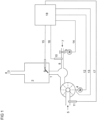
- FIG 1 Fig. 1 shows a combustion device 1 such as a wall mounted gas burner and/or an oil burner.
- a flame of a heat generator burns in the combustion chamber 2 of the combustion device 1 .
- the heat generator exchanges the thermal energy of the hot combustion gases into another fluid such as water.
- a hot water heating system is operated and / or heated drinking water.
- a good can be heated, for example in an industrial process, with the thermal energy of the hot fuels and/or combustion gases.
- the heat generator is part of a system with combined heat and power generation, for example a motor of such a system.
- the heat generator is a gas turbine.
- the heat generator can be used to heat water in a plant for the production of lithium and/or lithium carbonate.
- the exhaust gases 3 are discharged from the combustion chamber 2, for example via a chimney.
- the air supply 5 for the combustion process is supplied via a fan 4 driven (by a motor). Via the signal line 12, a control and/or regulating device 18 specifies the air supply V L to the blower 4 that it is to convey. The fan speed thus becomes a measure of the air supply 5.
- the fan speed is reported back to the control and/or regulation device 18 by the fan 4 .
- control and/or regulating device 18 determines the speed of fan 4 via signal line 13.
- the control and/or regulation device 18 preferably includes a microcontroller.
- the control and/or regulation device 18 ideally includes a microprocessor.
- the control and/or regulating device 18 can be a regulating device.
- the control device preferably includes a microcontroller.
- the control device ideally includes a microprocessor.
- the controller may include a proportional and integral controller.
- the control device can comprise a proportional and integral and derivative controller.
- control and/or regulation device 18 can include a field-programmable (logic) gate arrangement.
- control and/or regulation device 18 can comprise an application-specific integrated circuit.
- the signal line 12 comprises an optical waveguide.
- the signal line 13 for determining the fan speed can also include an optical waveguide.
- the signal lines 12 and 13 are designed as optical waveguides. Optical fibers provide advantages in terms of galvanic isolation and protection against explosions.
- the flap and/or valve position can be used as a measure for the air supply 5 .
- a measured value derived from the signal of a pressure sensor and/or mass flow sensor and/or volume flow sensor can be used.
- the sensor 11 is advantageously arranged in the duct 5 for the air supply.
- the sensor 11 advantageously provides a signal which is converted into a flow measurement value using a suitable signal processing unit.
- the signal from the sensor 11 is reported back using a signal line 17 .
- a signal can be reported back to the control and/or regulating device 18 using the signal line 17 , which signal is a measure of an air supply 5 .
- the signal line 17 can comprise an optical waveguide.
- Optical fibers provide advantages in terms of galvanic isolation and protection against explosions.
- a suitable signal processing device for processing the signal of the sensor 11 ideally includes at least one analog-to-digital converter.
- the signal processing device, in particular the analog/digital converter(s) is integrated in the control and/or regulation device 18.
- the measured value of a pressure sensor and/or a mass flow sensor in a side channel of the air supply 5 can also be used as a measure for the air supply V L .
- a combustion device with feed channel and side channel is for example in the European patent EP3301364B1 disclosed.
- the European patent EP3301364B1 was published on June 7, 2017 filed and granted on August 7, 2019.
- a combustion device with a supply channel and a side channel is claimed, with a mass flow sensor protruding into the supply channel.
- a pressure sensor and/or a mass flow sensor in the side channel determines a signal which corresponds to the pressure value dependent on the air supply V L and/or the air flow (particle flow and/or mass flow) in the side channel.
- the sensor advantageously provides a signal which is converted into a measured value using a suitable signal processing device.
- the signals from a number of sensors are converted into a common measured value.
- a suitable signal processing device ideally includes at least one analog-to-digital converter.
- the signal processing device, in particular the analog/digital converter or converters is integrated in the control and/or regulating device 18.
- the signal processing device, in particular the analog/digital converter or converters is integrated in the pressure sensor and/or mass flow sensor.
- the sensor signals are transmitted to the control and/or regulation device 18 via a communication interface with a specified communication bus protocol.
- the air supply V L is the value of the current air flow rate.
- the air flow rate may be measured and/or reported in cubic meters of air per hour.
- the air supply V L can be measured and/or stated in cubic meters of air per hour.
- Mass flow sensors allow measurement at high flow velocities, especially in connection with combustion devices during operation. Typical values of such flow velocities are in the ranges between 0.1 meters per second and 5 meters per second, 10 meters per second, 15 meters per second, 20 meters per second, or even 100 meters per second.
- Mass flow sensors suitable for the present disclosure are, for example, OMRON® D6F-W or type SENSOR TECHNICS® WBA sensors. The usable range of these sensors typically starts at speeds between 0.01 meters per second and 0.1 meters per second and ends at a speed such as 5 meters per second, 10 meters per second, 15 meters per second, 20 meters per second, or even 100 meters per second. In other words, it can have lower limits like 0.1 meters per second be combined with upper limits such as 5 meters per second, 10 meters per second, 15 meters per second, 20 meters per second, or even 100 meters per second.
- the fuel supply V B is set and/or regulated by the control and/or regulation device 18 with the aid of a fuel actuator and/or a valve 6 that can be adjusted (by a motor).
- the fuel 7 is a fuel gas.
- a combustor 1 can then be connected to various fuel gas sources, for example sources with a high proportion of methane and/or sources with a high proportion of propane. Provision is also made for the combustion device 1 to be connected to a source of a gas or a gas mixture, the gas or the gas mixture comprising hydrogen.
- the quantity of fuel gas is set by the control and/or regulating device 18 by means of a (motor-driven) adjustable fuel valve 6 .
- the control value, for example a pulse width modulated signal, of the gas valve is a measure of the amount of fuel gas. It is also a value for the fuel supply V B .
- a gas valve is used as the fuel actuator 6, the position of a valve can be used as a measure for the quantity of fuel gas.
- a fuel actuator 6 and/or a fuel valve are set using a stepping motor. In that case, the stepping position of the stepping motor is a measure of the amount of fuel gas.
- the fuel valve can also be integrated in a unit with at least one or more safety shut-off valves.
- a signal line 14 connects the fuel actuator 6 to the open-loop and/or closed-loop control device 18.
- the signal line 14 comprises an optical waveguide. Optical fibers provide advantages in terms of galvanic isolation and protection against explosions.
- the fuel valve 6 can be a valve that is controlled internally via a flow and/or pressure sensor 10, which valve receives a target value and regulates the actual value of the flow and/or pressure sensor 10 to the target value.
- the flow and/or pressure sensor 10 can be implemented as a volume flow sensor, for example as a turbine wheel meter or as a bellows meter or as a differential pressure sensor.
- the flow and/or pressure sensor 10 can also be designed as a mass flow sensor, for example as a thermal mass flow sensor.
- a signal line 16 connects the flow and/or pressure sensor 10 to the control and/or regulation device 18.
- the signal line 16 comprises an optical waveguide. Optical fibers provide advantages in terms of galvanic isolation and protection against explosions.
- the flow and/or pressure sensor 10 is arranged separately from the fuel valve 6 in the fuel supply channel 8 .
- the flow sensor 10 can be implemented as a volume flow sensor, for example as a turbine wheel meter or bellows meter or as a differential pressure sensor.
- the flow and / or pressure sensor 10 can also be used as Mass flow sensor, for example, be designed as a thermal mass flow sensor.
- a signal line 16 connects the flow and/or pressure sensor 10 to the control and/or regulation device 18.
- the signal line 16 comprises an optical waveguide. Optical fibers provide advantages in terms of galvanic isolation and protection against explosions.
- That flow and/or pressure sensor 10 generates a signal which is converted into a flow measurement value (measurement value of the particle and/or mass flow and/or volume flow) using a suitable signal processing device.
- a suitable signal processing device ideally includes at least one analog-to-digital converter.
- the signal processing device in particular the analog/digital converter or converters, is integrated in the control and/or regulation device 18.
- the signal processing device in particular the analog/digital converter or converters, is integrated in the flow - and/or pressure sensor.
- the sensor signals are transmitted to the control and/or regulation device 18 via a communication interface with a specified communication bus protocol.
- FIG 1 also shows a combustion device 1 with a combustion sensor 9 for detecting an air ratio ⁇ .
- the combustion sensor 9 can comprise an ionization electrode, for example.
- the combustion sensor 9 can also be an ionization electrode.
- KANTHAL ® eg APM ® or A-1 ® , is often used as the material for an ionization electrode. Electrodes made of Nikrothal ® are also considered by those skilled in the art.
- the combustion sensor 9 is preferably arranged in the combustion chamber 2 .
- a signal line 15 connects the combustion sensor 9 to the control and/or regulating device 18.
- the signal line 15 comprises an optical waveguide.
- Optical fibers provide advantages in terms of galvanic isolation and protection against explosions.
- the combustion sensor 9 is connected to a voltage source via an impedance.
- the impedance for connection to the voltage source can include an electrical resistance, in particular an electrical, ohmic resistance.
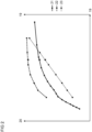
- curve 21 by way of example setpoint values for the signals from a combustion sensor 9 .
- Curve 22 shows exemplary reference values for the drift test from the signals from a combustion sensor 9 over an air supply or fan speed or output 19 .
- curves 21 and 22 can show ionization current values 20 over air supply or blower speed or output 19 .
- the air supply or fan speed or output 19 along the abscissa is preferably an air supply or fan speed or output 19 of a combustion device 1.
- the curve 21 in FIG 2 shows nominal values of the signals of a combustion sensor 9 in the as-delivered state of the at least one combustion sensor 9.
- the curve 21 shows ionization current nominal values in the as-delivered state of an ionization electrode for normal control operation.
- the curve 21 is supported by a number of values for the air supply or fan speed or output 19 .
- target values of the ionization current of an ionization electrode can be present in the delivery state.
- FIG 2 sixteen such supporting values of the air supply or fan speed or output 19 are shown as an example for curve 21 .
- a target value of a signal from a combustion sensor 9 in the delivery state belongs to each supporting value of the air supply or fan speed or output 19 .
- a target value of an ionization current of an ionization electrode in the delivery state can belong to each supporting value of the air supply or fan speed or power 19 .
- the supporting values and the associated ionization current set values form the supporting points of the control curve for normal control operation in the delivery state of the control and/or regulating device 18.
- the supporting values are such supporting values for the air supply or fan speed or output 19.
- the curve 22 in FIG 2 shows reference values for a drift test of the at least one combustion sensor 9 for changes.
- curve 22 shows reference ionization currents for a drift test of an ionization electrode for change.
- a combustion sensor 9 or an ionization electrode can change, for example due to aging.
- aging can be accompanied by the formation of deposits on the combustion sensor 9 or on the ionization electrode.
- the curve 22 is supported by a number of values for the air supply or fan speed or output 19 .
- Reference values of the signal of the at least one combustion sensor 9 exist for those values of air supply or fan speed or power 19.
- reference values of the ionization current of an ionization electrode can be present for those values of air supply or fan speed or power 19.
- FIG 2 seven such supporting values of the air supply or fan speed or output 19 are shown as an example for curve 22 .
- a reference value of a signal from a combustion sensor 9 is associated with each supporting value of the air supply or fan speed or power 19.
- each supporting value of the air supply or fan speed or power 19 can be associated with a reference value of an ionization current for a drift test of an ionization electrode.
- the interpolation values of the air supply or fan speed or power 19 and the respective associated reference ionization currents form the interpolation points of the reference curve for drift tests of the ionization electrode.
- Support values for air supply or fan speed or power 19 for curve 22 are generally not identical to support values for air supply or fan speed or power 19 for curve 21.
- the respective support values for curves 21 and 22 can differ in number.
- the respective supporting values of the curves 21 and 22 can differ in their position. This means that the respective supporting values of the curves 21 and 22 do not belong to identical values of the air supply or fan speed or output 19.
- the curve 23 in FIG 2 represents the change in the air ratio ⁇ caused by the engine speed and/or the fuel valve during a drift test. In the present case, it represents a first, upper via a second, lower air supply or fan speed or output for a drift test of the at least one combustion sensor 9.
- the associated ordinate axis is the second ordinate axis. It covers the same range of values as the abscissa axis.
- Each air supply or fan speed or power 19 breakpoint of curve 23 is associated with an air supply or blower speed or power breakpoint 19 of curve 22.
- the air supply or blower speed or power breakpoints 19 of curve 23 correspond to the second, lower air supplies or fan speeds or powers for drift tests.
- drift test value ie a value determined from the associated test results by filtering, and an index for determining a test result are assigned to each of these drift test interpolation points.
- a reference value is assigned to each drift test node.
- the value on curve 21 corresponding to a base value of the air supply or fan speed or power 19 of curve 23 can be a base value of the air supply or fan speed or power 19 of curve 21 .
- the value on curve 21 corresponding to a base value of the air supply or fan speed or power 19 of curve 23 does not have to be a base value of the air supply or fan speed or power 19 of curve 21 .
- the values of curve 21 can be interpolated. For example, linear interpolation can be carried out between neighboring points. The interpolated value is then used to determine an associated reference value for normal control operation for a supporting value of curves 22 and 23 .
- a triangular point can be seen on each of the curves 21 to 23. These points all belong to the same air supply or blower speed or output 19. In contrast to the reference points, the point marked with a triangle corresponds to a calculated value. It can, for example, have been obtained by interpolation between the base points of each curve. A drift test can be carried out with the values obtained in this way and the test result can be evaluated or converted to the neighboring reference points.
- Intervals are formed for the decision as to whether a drift test is to be carried out on the basis of a current air supply or a current blower speed or a current output.
- the intervals are formed on the basis of the first air supply values or blower speed values or performance values of a drift test support point.
- the range of air supply or fan speed or power can be divided into intervals between the first air supply or fan speed or power of the highest and lowest drift test support point. In one embodiment, the entire range of airflow or fan speed or power is divided into intervals between the first airflow or fan speed or power of the highest and lowest drift test breakpoints.
- the intervals are selected on the basis of the first air supply values or fan speed values or performance values of the drift test support points.
- a first drift test support point P n is close to the current air supply or close to the current fan speed or close to the current power.
- a second drift test support point P n + 1 is further away from the current air supply or the current fan speed or the current power than the first drift test support point P n .
- the second drift test node P n + 1 is adjacent to the first drift test node P n .
- a first area is close to the first drift test node P n .
- Another range is between the drift test breakpoints P n and P n + 1 , but does not include the drift test breakpoints P n and P n + 1 .
- Yet another area is close to the second drift test node P n + 1 . Preferably, these areas do not overlap.
- each range covers one-third of the interval between the drift test vertices P n and P n + 1 .
- the region near P n encompasses a quarter of the interval between the drift test breakpoints P n and P n + 1 .
- the area near P n + 1 also covers a quarter of the interval between the drift test breakpoints P n and P n + 1 .
- the range between the drift test breakpoints P n and P n + 1 comprises half the interval between the drift test breakpoints P n and P n + 1 .
- a drift test is performed with an air supply or fan speed or output close to Pn , the new test result from this drift test is converted to Pn .
- This conversion is analogous to that in EP3045816B1 disclosed calculation for neighboring points.
- a new ionization current from this drift test can be converted to Pn .
- the time interval until a new drift test for P n is carried out is preferably restarted. If a drift test is started in the middle area between the drift test support points P n and P n + 1 , the new test result from this drift test is converted to P n and to P n + 1 .
- a new ionization current from this drift test can be converted to P n and P n + 1 .
- a weighting or filter value is preferably used when the converted test result is offset against the previous filtered drift test values at the drift test support points P n and P n + 1 .
- the time interval or time intervals can be restarted until a new drift test is performed.
- a drift test is carried out with an air supply or fan speed or output close to P n +1
- the new test result from this drift test is converted to P n +1 .
- a new ionization current from this drift test can be converted to Pn + 1 .
- the time interval until a new drift test for P n + 1 is carried out is preferably restarted.
- a drift test is performed when the time interval of a drift test node Pn has elapsed and the current air supply or fan speed or power is either in the range close to the drift test node or between drift test node Pn and Pn + 1 . If there is still a time interval running at the second drift test interpolation point P n + 1 before a drift test can be carried out, then that time interval can be left as it is. In a specific embodiment, a conversion to the second drift test support point P n + 1 can be dispensed with as long as the corresponding time interval has not yet expired. Consequently, the end of the time interval to the second drift test support point P n + 1 is awaited. After that time interval has elapsed, a drift test is performed at or near the second drift test node P n + 1 .
- the test conditions for the drift test are defined using two curves.
- the reference values in particular the reference ionization currents
- the reference values can be test results determined in the laboratory and/or reference values on a reference device and/or sample device.
- the reference values can be ionization currents in drift test executions.
- the reference values, in particular the reference ionization currents can be stored, for example, as support points or using curve parameters. Turn 22 off FIG 2 shows such breakpoints for reference values.
- the curve parameters can include curve parameters of the third, fourth, fifth or higher order, for example.
- the curve parameters can include parameters of polynomials of the third, fourth, fifth or higher order.
- the change in the air ratio ⁇ during a drift test must be determined relative to each other, for example by values of the air supply or fan speed or power during the drift test.
- a curve of the first air supply or first fan speed or first power over the second air supply or second fan speed or second power can be used for this purpose.
- One such curve is curve 23 off FIG 2 in the variant supporting points and interpolation for the intermediate values.
- a curve of the ratio of the first air supply or first fan speed or first power to the second air supply or second fan speed or second power can be used for this purpose. In the simplest case, this is sufficient for the ratio of the first air supply or first fan speed or first power to the second air supply or second fan speed or second power is a constant.
- a straight line is obtained as curve 23 as the curve of the first air supply or first fan speed or first power versus the second air supply or second fan speed or second power.
- curves of a higher order can also be used. It is possible that the values of the air supply or fan speed or power during the drift test are not defined in relation to each other via support points and interpolation for the intermediate values, but via a curve using polynomial coefficients.
- air supplies or fan speeds or outputs should also be specified, to which the measured drift of the combustion sensor 9 is converted.
- air supplies or blower speeds or outputs should be specified, to which the measured drift of the ionization electrode 9 is converted.
- the respective highest and lowest values of the air supply or fan speed or power must be defined, which define limits within which one or more drift tests can be carried out.
- such values are defined in a memory of a control and/or regulation device 18 .
- Those values, together with any other specified values for the air supply or fan speed or power, serve as values to which the measured drift of the combustion sensor 9 is converted. They are used as drift test breakpoints in the same manner as described above.
- conditions for the drift test are defined via curve parameters.
- conditions for the drift test can be defined using values stored in the memory of a control and/or regulating device 18 .
- P n there are few drift test support points.
- the distance from the current air supply or fan speed or power to the drift test support point P n , P n + 1 can be used as a parameter.
- the converted, new test result flows into the filtered drift test value at the support point P n , P n + 1 .
- the weighting of the converted, new test result is higher the closer the current air supply or fan speed or power is to the drift test support point P n , P n + 1 .
- the closer the current air supply or blower speed or output is to the drift test support point P n , P n + 1 the longer the time until the next drift test is due.
- a new test result is determined at a current air supply or fan speed or output 24 and converted to the drift test points P n , P n + 1 .
- the current air supply or fan speed or power 24 is spaced two-fifths of the interval from P n to P n + 1 to the first drift test vertex P n .
- the current air supply or fan speed or power 24 has a distance of three fifths of the interval from P n to P n + 1 to the second drift test support point P n + 1 .
- the second drift test node P n + 1 is adjacent to the first drift test node P n .
- the new test result converted to the drift test base P n is now filtered at the previous filtered drift test value assigned to this drift test base.
- the filtering only takes place with a weighting of three-fifths compared to a test result that would have been determined exactly at the drift test node P n .
- a converted new test result can be filtered on the previous, filtered drift test value assigned to this drift test node.
- the filtering is only carried out with a weighting of three-fifths compared to a test result that would have been determined exactly at the drift test support point P n .
- the new test result converted to the second drift test node P n + 1 is filtered at the previous filtered drift test value assigned to this drift test node.
- the filtering is only carried out with a weighting of two-fifths compared to a test result that would have been determined exactly at the drift test node P n +1 .
- a converted, new test result can be filtered on the previous, filtered drift test value assigned to this drift test node.
- the filtering is only carried out with a weighting of two-fifths compared to a test result that would have been determined exactly at the drift test node P n +1 .
- the weighting is not necessarily varied between zero and one hundred percent via the relative position of the current air supply or fan speed or output in the interval P n to P n + 1 .
- a filter value 27 is defined for at least one drift test interpolation point P n , P n + 1 .
- a filter value can be defined for each drift test interpolation point P n , P n + 1 .
- a filter value of forty percent can be defined for a drift test base.
- a filter value of forty percent can be defined in the memory of a control and/or regulating device 18 for a drift test support point.
- This filter value corresponds to the weighting factor with which a converted test result based on a test at point P n is filtered to the previous filtered drift test value assigned to the drift test interpolation point P n + 1 .
- Parts of a control and/or regulation device 18 according to the present disclosure can be implemented as hardware and/or as a software module, which is executed by a computing unit, optionally with the addition of container virtualization, and/or using a cloud computer and/or using a combination of the aforementioned opportunities are realized.
- the software may include firmware and/or a hardware driver running within an operating system and/or container virtualization and/or an application program.
- the present disclosure also relates to a computer program product, which contains the features of this disclosure or carries out the necessary steps. When implemented in software, the functions described may be stored as one or more instructions on a computer-readable medium.
- RAM random access memory
- MRAM magnetic random access memory
- ROM read only memory
- EPROM electronically programmable ROM
- EEPROM electronically programmable and erasable ROM
Landscapes
- Engineering & Computer Science (AREA)
- Chemical & Material Sciences (AREA)
- Combustion & Propulsion (AREA)
- Mechanical Engineering (AREA)
- General Engineering & Computer Science (AREA)
- Regulation And Control Of Combustion (AREA)
Priority Applications (1)
| Application Number | Priority Date | Filing Date | Title |
|---|---|---|---|
| US17/864,846 US12565995B2 (en) | 2021-07-16 | 2022-07-14 | Closed-loop control of a combustion apparatus |
Applications Claiming Priority (1)
| Application Number | Priority Date | Filing Date | Title |
|---|---|---|---|
| EP21186036 | 2021-07-16 |
Publications (3)
| Publication Number | Publication Date |
|---|---|
| EP4119847A1 EP4119847A1 (de) | 2023-01-18 |
| EP4119847C0 EP4119847C0 (de) | 2023-06-14 |
| EP4119847B1 true EP4119847B1 (de) | 2023-06-14 |
Family
ID=76958769
Family Applications (1)
| Application Number | Title | Priority Date | Filing Date |
|---|---|---|---|
| EP22154894.4A Active EP4119847B1 (de) | 2021-07-16 | 2022-02-03 | Verbrennungsvorrichtung mit regelungseinrichtung |
Country Status (4)
| Country | Link |
|---|---|
| US (1) | US12565995B2 (pl) |
| EP (1) | EP4119847B1 (pl) |
| ES (1) | ES2955937T3 (pl) |
| PL (1) | PL4119847T3 (pl) |
Cited By (1)
| Publication number | Priority date | Publication date | Assignee | Title |
|---|---|---|---|---|
| EP4545854A1 (de) | 2023-10-25 | 2025-04-30 | Siemens Aktiengesellschaft | Regelung einer verbrennungsvorrichtung |
Family Cites Families (8)
| Publication number | Priority date | Publication date | Assignee | Title |
|---|---|---|---|---|
| DE19618573C1 (de) * | 1996-05-09 | 1997-06-26 | Stiebel Eltron Gmbh & Co Kg | Verfahren und Einrichtung zum Betrieb eines Gasbrenners |
| DE59604283D1 (de) * | 1995-10-25 | 2000-03-02 | Stiebel Eltron Gmbh & Co Kg | Verfahren und Schaltung zur Regelung eines Gasbrenners |
| US8773137B2 (en) * | 2008-03-07 | 2014-07-08 | Bertelli & Partners, S.R.L. | Method and device to detect the flame in a burner operating on a solid, liquid or gaseous combustible |
| EP2466204B1 (de) | 2010-12-16 | 2013-11-13 | Siemens Aktiengesellschaft | Regeleinrichtung für eine Brenneranlage |
| EP3045816B1 (de) | 2015-01-19 | 2018-12-12 | Siemens Aktiengesellschaft | Einrichtung zur regelung einer brenneranlage |
| EP3290800B1 (de) * | 2016-09-02 | 2021-03-24 | Robert Bosch GmbH | Verfahren zum aktualisieren einer kennlinie in einem heizsystem sowie eine steuereinheit und ein heizsystem |
| HUE046690T2 (hu) | 2016-09-30 | 2020-03-30 | Siemens Ag | Égetõberendezés égõvel és turbulens áramlásokhoz átfolyásmérõ egységgel |
| ES2902010T3 (es) * | 2017-03-27 | 2022-03-24 | Siemens Ag | Detección de un bloqueo |
-
2022
- 2022-02-03 PL PL22154894.4T patent/PL4119847T3/pl unknown
- 2022-02-03 EP EP22154894.4A patent/EP4119847B1/de active Active
- 2022-02-03 ES ES22154894T patent/ES2955937T3/es active Active
- 2022-07-14 US US17/864,846 patent/US12565995B2/en active Active
Cited By (1)
| Publication number | Priority date | Publication date | Assignee | Title |
|---|---|---|---|---|
| EP4545854A1 (de) | 2023-10-25 | 2025-04-30 | Siemens Aktiengesellschaft | Regelung einer verbrennungsvorrichtung |
Also Published As
| Publication number | Publication date |
|---|---|
| ES2955937T3 (es) | 2023-12-11 |
| US12565995B2 (en) | 2026-03-03 |
| EP4119847C0 (de) | 2023-06-14 |
| US20230017088A1 (en) | 2023-01-19 |
| PL4119847T3 (pl) | 2023-10-30 |
| EP4119847A1 (de) | 2023-01-18 |
Similar Documents
| Publication | Publication Date | Title |
|---|---|---|
| EP3301362B1 (de) | Verfahren zur regelung turbulenter strömungen | |
| EP2449234B1 (de) | Verfahren zur regelung eines gasmotors | |
| EP2466204B1 (de) | Regeleinrichtung für eine Brenneranlage | |
| DE102017204021A1 (de) | Verfahren zum Aktualisieren einer Kennlinie in einem Heizsystem sowie eine Steuereinheit und ein Heizsystem | |
| EP3045816B1 (de) | Einrichtung zur regelung einer brenneranlage | |
| EP3299718B1 (de) | Gasartenerkennung | |
| EP1902254A1 (de) | Verfahren zur regelung und steuerung einer feuerungseinrichtung und feuerungseinrichtung | |
| EP1002999A2 (de) | Regelung der Brennerheizleistung bei einem gasbetriebenen Koch- oder Backgerät | |
| EP1936183A2 (de) | Verfahren zur Regelung der Temperatur einer Glühkerze einer Brennkraftmaschine | |
| EP4119847B1 (de) | Verbrennungsvorrichtung mit regelungseinrichtung | |
| EP3382277A1 (de) | Erkennung einer abdeckung | |
| EP1481153B1 (de) | Verfahren zum steuern einer brennkraftmaschine | |
| DE2509344C3 (de) | Verfahren und Anordnung zur automatischen Regelung einer Kessel-Turbinen-Einheit | |
| EP4141340A1 (de) | Heizvorrichtung | |
| DE102017126138A1 (de) | Verfahren zur Regelung eines brenngasbetriebenen Heizgerätes | |
| DE102011111453A1 (de) | Verfahren zur Luftzahleinstellung bei einem Heizgerät | |
| EP4050258B1 (de) | Verfahren zur regelung einer brennereinrichtung mit leistungsermittlung über einen brennstoffparameter | |
| DE102014224891A1 (de) | Heizgerätevorrichtung und Verfahren zum Betrieb einer Heizgerätevorrichtung | |
| AT413738B (de) | Verfahren zum regeln einer brennkraftmaschine | |
| EP2615278B1 (de) | Dosiereinrichtung mit einem Gasmischer und Verfahren zur Steuerung der Gemischbildung | |
| EP4060233B1 (de) | Leistungserfassung und luftzahlregelung mittels sensoren im feuerraum | |
| DE102004055715C5 (de) | Verfahren zur Einstellung von Betriebsparametern an einer Feuerungseinrichtung und Feuerungseinrichtung | |
| EP0239842B1 (de) | Verfahren zum Regeln der Innenraumtemperatur, insbesondere eines Kraftfahrzeugs | |
| EP3290800B1 (de) | Verfahren zum aktualisieren einer kennlinie in einem heizsystem sowie eine steuereinheit und ein heizsystem | |
| DE102015225886A1 (de) | Heizgerätesystem und Verfahren mit einem Heizgerätesystem |
Legal Events
| Date | Code | Title | Description |
|---|---|---|---|
| PUAI | Public reference made under article 153(3) epc to a published international application that has entered the european phase |
Free format text: ORIGINAL CODE: 0009012 |
|
| STAA | Information on the status of an ep patent application or granted ep patent |
Free format text: STATUS: REQUEST FOR EXAMINATION WAS MADE |
|
| 17P | Request for examination filed |
Effective date: 20220719 |
|
| AK | Designated contracting states |
Kind code of ref document: A1 Designated state(s): AL AT BE BG CH CY CZ DE DK EE ES FI FR GB GR HR HU IE IS IT LI LT LU LV MC MK MT NL NO PL PT RO RS SE SI SK SM TR |
|
| GRAP | Despatch of communication of intention to grant a patent |
Free format text: ORIGINAL CODE: EPIDOSNIGR1 |
|
| STAA | Information on the status of an ep patent application or granted ep patent |
Free format text: STATUS: GRANT OF PATENT IS INTENDED |
|
| INTG | Intention to grant announced |
Effective date: 20230315 |
|
| GRAS | Grant fee paid |
Free format text: ORIGINAL CODE: EPIDOSNIGR3 |
|
| GRAA | (expected) grant |
Free format text: ORIGINAL CODE: 0009210 |
|
| STAA | Information on the status of an ep patent application or granted ep patent |
Free format text: STATUS: THE PATENT HAS BEEN GRANTED |
|
| AK | Designated contracting states |
Kind code of ref document: B1 Designated state(s): AL AT BE BG CH CY CZ DE DK EE ES FI FR GB GR HR HU IE IS IT LI LT LU LV MC MK MT NL NO PL PT RO RS SE SI SK SM TR |
|
| REG | Reference to a national code |
Ref country code: CH Ref legal event code: EP |
|
| REG | Reference to a national code |
Ref country code: DE Ref legal event code: R096 Ref document number: 502022000035 Country of ref document: DE |
|
| REG | Reference to a national code |
Ref country code: AT Ref legal event code: REF Ref document number: 1579464 Country of ref document: AT Kind code of ref document: T Effective date: 20230715 |
|
| U01 | Request for unitary effect filed |
Effective date: 20230710 |
|
| U07 | Unitary effect registered |
Designated state(s): AT BE BG DE DK EE FI FR IT LT LU LV MT NL PT SE SI Effective date: 20230720 |
|
| REG | Reference to a national code |
Ref country code: LT Ref legal event code: MG9D |
|
| PG25 | Lapsed in a contracting state [announced via postgrant information from national office to epo] |
Ref country code: NO Free format text: LAPSE BECAUSE OF FAILURE TO SUBMIT A TRANSLATION OF THE DESCRIPTION OR TO PAY THE FEE WITHIN THE PRESCRIBED TIME-LIMIT Effective date: 20230914 |
|
| PG25 | Lapsed in a contracting state [announced via postgrant information from national office to epo] |
Ref country code: RS Free format text: LAPSE BECAUSE OF FAILURE TO SUBMIT A TRANSLATION OF THE DESCRIPTION OR TO PAY THE FEE WITHIN THE PRESCRIBED TIME-LIMIT Effective date: 20230614 Ref country code: HR Free format text: LAPSE BECAUSE OF FAILURE TO SUBMIT A TRANSLATION OF THE DESCRIPTION OR TO PAY THE FEE WITHIN THE PRESCRIBED TIME-LIMIT Effective date: 20230614 Ref country code: GR Free format text: LAPSE BECAUSE OF FAILURE TO SUBMIT A TRANSLATION OF THE DESCRIPTION OR TO PAY THE FEE WITHIN THE PRESCRIBED TIME-LIMIT Effective date: 20230915 |
|
| REG | Reference to a national code |
Ref country code: ES Ref legal event code: FG2A Ref document number: 2955937 Country of ref document: ES Kind code of ref document: T3 Effective date: 20231211 |
|
| PG25 | Lapsed in a contracting state [announced via postgrant information from national office to epo] |
Ref country code: SK Free format text: LAPSE BECAUSE OF FAILURE TO SUBMIT A TRANSLATION OF THE DESCRIPTION OR TO PAY THE FEE WITHIN THE PRESCRIBED TIME-LIMIT Effective date: 20230614 |
|
| PG25 | Lapsed in a contracting state [announced via postgrant information from national office to epo] |
Ref country code: IS Free format text: LAPSE BECAUSE OF FAILURE TO SUBMIT A TRANSLATION OF THE DESCRIPTION OR TO PAY THE FEE WITHIN THE PRESCRIBED TIME-LIMIT Effective date: 20231014 |
|
| PG25 | Lapsed in a contracting state [announced via postgrant information from national office to epo] |
Ref country code: SM Free format text: LAPSE BECAUSE OF FAILURE TO SUBMIT A TRANSLATION OF THE DESCRIPTION OR TO PAY THE FEE WITHIN THE PRESCRIBED TIME-LIMIT Effective date: 20230614 Ref country code: SK Free format text: LAPSE BECAUSE OF FAILURE TO SUBMIT A TRANSLATION OF THE DESCRIPTION OR TO PAY THE FEE WITHIN THE PRESCRIBED TIME-LIMIT Effective date: 20230614 Ref country code: RO Free format text: LAPSE BECAUSE OF FAILURE TO SUBMIT A TRANSLATION OF THE DESCRIPTION OR TO PAY THE FEE WITHIN THE PRESCRIBED TIME-LIMIT Effective date: 20230614 Ref country code: IS Free format text: LAPSE BECAUSE OF FAILURE TO SUBMIT A TRANSLATION OF THE DESCRIPTION OR TO PAY THE FEE WITHIN THE PRESCRIBED TIME-LIMIT Effective date: 20231014 Ref country code: CZ Free format text: LAPSE BECAUSE OF FAILURE TO SUBMIT A TRANSLATION OF THE DESCRIPTION OR TO PAY THE FEE WITHIN THE PRESCRIBED TIME-LIMIT Effective date: 20230614 |
|
| REG | Reference to a national code |
Ref country code: DE Ref legal event code: R097 Ref document number: 502022000035 Country of ref document: DE |
|
| U20 | Renewal fee for the european patent with unitary effect paid |
Year of fee payment: 3 Effective date: 20240219 |
|
| PLBE | No opposition filed within time limit |
Free format text: ORIGINAL CODE: 0009261 |
|
| STAA | Information on the status of an ep patent application or granted ep patent |
Free format text: STATUS: NO OPPOSITION FILED WITHIN TIME LIMIT |
|
| 26N | No opposition filed |
Effective date: 20240315 |
|
| PG25 | Lapsed in a contracting state [announced via postgrant information from national office to epo] |
Ref country code: MC Free format text: LAPSE BECAUSE OF FAILURE TO SUBMIT A TRANSLATION OF THE DESCRIPTION OR TO PAY THE FEE WITHIN THE PRESCRIBED TIME-LIMIT Effective date: 20230614 |
|
| PG25 | Lapsed in a contracting state [announced via postgrant information from national office to epo] |
Ref country code: IE Free format text: LAPSE BECAUSE OF NON-PAYMENT OF DUE FEES Effective date: 20240203 |
|
| PG25 | Lapsed in a contracting state [announced via postgrant information from national office to epo] |
Ref country code: IE Free format text: LAPSE BECAUSE OF NON-PAYMENT OF DUE FEES Effective date: 20240203 |
|
| U20 | Renewal fee for the european patent with unitary effect paid |
Year of fee payment: 4 Effective date: 20250220 |
|
| PGFP | Annual fee paid to national office [announced via postgrant information from national office to epo] |
Ref country code: PL Payment date: 20250123 Year of fee payment: 4 |
|
| PGFP | Annual fee paid to national office [announced via postgrant information from national office to epo] |
Ref country code: ES Payment date: 20250520 Year of fee payment: 4 |
|
| PGFP | Annual fee paid to national office [announced via postgrant information from national office to epo] |
Ref country code: CH Payment date: 20250512 Year of fee payment: 4 |
|
| PG25 | Lapsed in a contracting state [announced via postgrant information from national office to epo] |
Ref country code: CY Free format text: LAPSE BECAUSE OF FAILURE TO SUBMIT A TRANSLATION OF THE DESCRIPTION OR TO PAY THE FEE WITHIN THE PRESCRIBED TIME-LIMIT; INVALID AB INITIO Effective date: 20220203 |
|
| PG25 | Lapsed in a contracting state [announced via postgrant information from national office to epo] |
Ref country code: TR Free format text: LAPSE BECAUSE OF FAILURE TO SUBMIT A TRANSLATION OF THE DESCRIPTION OR TO PAY THE FEE WITHIN THE PRESCRIBED TIME-LIMIT Effective date: 20230614 |
|
| U20 | Renewal fee for the european patent with unitary effect paid |
Year of fee payment: 5 Effective date: 20260219 |
|
| PGFP | Annual fee paid to national office [announced via postgrant information from national office to epo] |
Ref country code: GB Payment date: 20260310 Year of fee payment: 5 |