EP4119846B1 - Verfahren und steuergerät zum betrieb eines gasbrennergeräts - Google Patents
Verfahren und steuergerät zum betrieb eines gasbrennergeräts Download PDFInfo
- Publication number
- EP4119846B1 EP4119846B1 EP21185474.0A EP21185474A EP4119846B1 EP 4119846 B1 EP4119846 B1 EP 4119846B1 EP 21185474 A EP21185474 A EP 21185474A EP 4119846 B1 EP4119846 B1 EP 4119846B1
- Authority
- EP
- European Patent Office
- Prior art keywords
- gas
- absolute pressure
- safety valve
- pressure
- gas safety
- Prior art date
- Legal status (The legal status is an assumption and is not a legal conclusion. Google has not performed a legal analysis and makes no representation as to the accuracy of the status listed.)
- Active
Links
Images
Classifications
-
- F—MECHANICAL ENGINEERING; LIGHTING; HEATING; WEAPONS; BLASTING
- F23—COMBUSTION APPARATUS; COMBUSTION PROCESSES
- F23N—REGULATING OR CONTROLLING COMBUSTION
- F23N5/00—Systems for controlling combustion
- F23N5/02—Systems for controlling combustion using devices responsive to thermal changes or to thermal expansion of a medium
- F23N5/12—Systems for controlling combustion using devices responsive to thermal changes or to thermal expansion of a medium using ionisation-sensitive elements, i.e. flame rods
- F23N5/123—Systems for controlling combustion using devices responsive to thermal changes or to thermal expansion of a medium using ionisation-sensitive elements, i.e. flame rods using electronic means
-
- F—MECHANICAL ENGINEERING; LIGHTING; HEATING; WEAPONS; BLASTING
- F23—COMBUSTION APPARATUS; COMBUSTION PROCESSES
- F23N—REGULATING OR CONTROLLING COMBUSTION
- F23N1/00—Regulating fuel supply
- F23N1/02—Regulating fuel supply conjointly with air supply
- F23N1/022—Regulating fuel supply conjointly with air supply using electronic means
-
- F—MECHANICAL ENGINEERING; LIGHTING; HEATING; WEAPONS; BLASTING
- F23—COMBUSTION APPARATUS; COMBUSTION PROCESSES
- F23N—REGULATING OR CONTROLLING COMBUSTION
- F23N1/00—Regulating fuel supply
- F23N1/02—Regulating fuel supply conjointly with air supply
- F23N1/025—Regulating fuel supply conjointly with air supply using electrical or electromechanical means
-
- F—MECHANICAL ENGINEERING; LIGHTING; HEATING; WEAPONS; BLASTING
- F23—COMBUSTION APPARATUS; COMBUSTION PROCESSES
- F23N—REGULATING OR CONTROLLING COMBUSTION
- F23N5/00—Systems for controlling combustion
- F23N5/24—Preventing development of abnormal or undesired conditions, i.e. safety arrangements
- F23N5/242—Preventing development of abnormal or undesired conditions, i.e. safety arrangements using electronic means
-
- F—MECHANICAL ENGINEERING; LIGHTING; HEATING; WEAPONS; BLASTING
- F23—COMBUSTION APPARATUS; COMBUSTION PROCESSES
- F23N—REGULATING OR CONTROLLING COMBUSTION
- F23N5/00—Systems for controlling combustion
- F23N5/18—Systems for controlling combustion using detectors sensitive to rate of flow of air or fuel
- F23N2005/181—Systems for controlling combustion using detectors sensitive to rate of flow of air or fuel using detectors sensitive to rate of flow of air
-
- F—MECHANICAL ENGINEERING; LIGHTING; HEATING; WEAPONS; BLASTING
- F23—COMBUSTION APPARATUS; COMBUSTION PROCESSES
- F23N—REGULATING OR CONTROLLING COMBUSTION
- F23N2223/00—Signal processing; Details thereof
- F23N2223/38—Remote control
-
- F—MECHANICAL ENGINEERING; LIGHTING; HEATING; WEAPONS; BLASTING
- F23—COMBUSTION APPARATUS; COMBUSTION PROCESSES
- F23N—REGULATING OR CONTROLLING COMBUSTION
- F23N2225/00—Measuring
- F23N2225/04—Measuring pressure
- F23N2225/06—Measuring pressure for determining flow
-
- F—MECHANICAL ENGINEERING; LIGHTING; HEATING; WEAPONS; BLASTING
- F23—COMBUSTION APPARATUS; COMBUSTION PROCESSES
- F23N—REGULATING OR CONTROLLING COMBUSTION
- F23N2233/00—Ventilators
- F23N2233/06—Ventilators at the air intake
- F23N2233/08—Ventilators at the air intake with variable speed
-
- F—MECHANICAL ENGINEERING; LIGHTING; HEATING; WEAPONS; BLASTING
- F23—COMBUSTION APPARATUS; COMBUSTION PROCESSES
- F23N—REGULATING OR CONTROLLING COMBUSTION
- F23N2235/00—Valves, nozzles or pumps
- F23N2235/12—Fuel valves
- F23N2235/16—Fuel valves variable flow or proportional valves
-
- F—MECHANICAL ENGINEERING; LIGHTING; HEATING; WEAPONS; BLASTING
- F23—COMBUSTION APPARATUS; COMBUSTION PROCESSES
- F23N—REGULATING OR CONTROLLING COMBUSTION
- F23N2241/00—Applications
- F23N2241/04—Heating water
Definitions
- the invention relates to a method for operating a gas burner appliance. Further on, the invention relates to a gas burner appliance comprising a controller for operating a gas burner appliance.
- EP 2 667 097 A1 discloses a method for operating a gas burner appliance.
- a gas/air mixture having a defined mixing ratio of gas and air is provided to a combustion chamber for combusting the gas/air mixture.
- the mixing ratio of gas and air of the gas/air mixture corresponds to the so-called ⁇ -value of the gas/air mixture.
- the gas/air mixture is provided by a mixing device mixing an air flow provided by an air duct with a gas flow provided by a gas duct.
- the mixing device may be provided by a Venturi nozzle.
- the air flow flowing through the air duct is provided by fan in such a way that the nominal fan speed of the fan depends on a nominal burner-load of the gas burner appliance, wherein a fan speed range of the fan defines a so-called modulation range of the gas burner appliance.
- a pneumatic gas flow regulator is provided by a gas armature.
- the gas armature comprises a safety gas valve and a throttle used for calibration.
- the pneumatic gas flow regulator uses a pressure difference between the gas pressure of the gas flow in the gas duct and a reference pressure, wherein either the air pressure of the air flow in the air duct or the ambient pressure is used as reference pressure, and wherein the pressure difference between the gas pressure of the gas flow in the gas duct and the reference pressure is determined and controlled pneumatically.
- EP 2 667 097 A1 discloses a method for operating a gas burner appliance in which the defined mixing ratio of the gas/air mixture is kept constant over the entire modulation range of the gas burner. This is done by the pneumatic gas flow regulator establishing a pneumatic control to keep the mixing ratio of gas and air within the gas/air mixture constant.
- pneumatic gas flow regulator instead of using pneumatic gas flow regulator, it is also known from prior art to control the mixing ratio of gas and air within the gas/air mixture by an electric or electronic gas flow modulator.
- the invention relates to a gas burner control making use of such an electric or electronic gas flow modulator.
- DE 198 24 521 A1 discloses a method to control the mixing ratio of gas and air of the gas/air mixture and thereby the ⁇ -value of the gas/air mixture on basis of a signal provided by an electrical or electronic sensor like an anemometer.
- An actual value corresponding to a pressure ratio between a gas pressure in a gas duct and an air pressure in an air duct or corresponding to a pressure ratio between the gas pressure in the gas duct and the air pressure at the reference point is provided by the electrical or electronic sensor, wherein this actual value is compared with a nominal value.
- a control variable for the electric or electronic gas flow modulator is generated on basis of the control deviation between the actual value and nominal value, wherein the electric gas flow modulator is adjusted on basis of this control variable to control the defined mixing ratio of gas and air in the gas/air mixture thereby keeping the ⁇ -value of the gas/air mixture constant.
- EP 2 405 198 B1 discloses a method for calibrating the regulation of a gas burner appliance.
- US 2006 / 0 292 505 A1 , JP 4 850 163 B2 , JP 2017 116382 A , US 2004/062290 A1 and US 2015/045971 A1 disclose other prior art.
- the amount of the air flow and thereby the amount of the flow of the gas/air mixture having the defined mixing ratio of gas and air provided to the burner chamber depends on the desired burner load.
- the nominal burner-load corresponds to a desired heat demand.
- the nominal burner-load defines the fan speed at which the fan is operated.
- the fan speed range of the fan of the gas burner appliance defines the modulation range of the gas burner appliance.
- a maximum fan speed of the fan defines the maximum burner-load of the gas burner appliance. If a desired heat demand requires maximum burner load, then the fan is operated at maximum fan speed. If a desired heat demand requires burner-load being 50% of the maximum burner load, then the fan is operated at 50% of the maximum fan speed. If a desired heat demand requires burner-load being 20% of the maximum burner load, then the fan is operated at 20% of the maximum fan speed.
- the mixing ratio of gas and air of the gas/air mixture is kept at a defined value, preferably constant.
- the combustion quality of the gas burner appliance may vary in view of a fluctuating gas inlet pressure. Further, the combustion quality of the gas burner appliance may vary in view of fluctuating weather conditions, namely in view of a fluctuating ambient air pressure.
- Gas burner appliances known from practice make use of a mechanical pressure regulator to compensate for a fluctuating gas inlet pressure.
- a mechanical pressure regulator may be provided as a separate unit of the gas burner appliance. Such mechanical pressure switches require additional installation space and cause additional hardware costs.
- a combustion quality sensor e. g. from a flame ionization sensor
- Such a compensation for a fluctuating gas inlet pressure making use of a combustion quality sensor first results into a poor combustion quality before it is possible to provide the compensation. Further, such a compensation for a fluctuating gas inlet pressure making use of a combustion quality sensor reacts slowly.
- the present invention provides an accurate react fast reacting method, as defined in claim 1, for operating a gas burner appliance to compensate at least for a fluctuating gas inlet pressure of the gas burner.
- the gas burner appliance is operated to compensate for a fluctuating gas inlet pressure of the gas burner appliance by executing the following steps: Measure a first absolute pressure by the absolute pressure sensor when at least the first gas safety valve of the gas safety valve unit is closed, the gas safety valve unit comprising a second gas safety valve downstream of the first gas safety valve. If the absolute pressure sensor is positioned downstream of the first gas safety valve and downstream of the second gas safety valve and upstream of a gas flow modulator, the second gas safety valve is closed or opened. If the absolute pressure sensor is positioned downstream of the first gas safe-ty valve and upstream of the second gas safety valve, then second gas safety valve is opened.
- the above method allows to compensate at least for a fluctuating gas inlet pressure of the gas burner appliance in an accurate and fast manner.
- the first absolute pressure is measured by the absolute pressure sensor when at least the first gas safety valve of the gas safety valve unit is closed and when the fan is stopped or when the fan is running, wherein - if the fan is running - the pressure depending on the first absolute pressure is determined from the measured first absolute pressure and from the fan speed, and then the pressure difference is determined between the pressure depending on the first absolute pressure and the second absolute pressure.
- the second absolute pressure is measured by the absolute pressure sensor when the gas safety valve unit is opened and when the fan is running.
- the pressure difference is determined between the first absolute pressure or the pressure depending on the first absolute pressure and the second absolute pressure, wherein the pressure difference may be adapted into an adapted pressure difference as a function of the fan speed, and the gas flow modulator may then be operated on basis of said adapted pressure difference to compensate for a fluctuating gas inlet pressure of the gas burner appliance. This further improves the accuracy of the compensation for a fluctuating gas inlet pressure of the gas burner appliance.
- the following steps are executed: Measure the first absolute pressure when at least the first gas safety valve of the gas safety valve unit is closed. Then open the gas safety valve unit, run the fan at a defined fan speed, activate an ignition device and measure continuously or at a defined sampling rate the second absolute pressure while increasing the opening position of the gas flow modulator. Determine continuously or at the defined sampling rate the pressure difference. Adjust continuously or at the defined sampling rate the opening position of the gas flow modulator dependent from said pressure difference. This allows to provide a very favorable start-up of the gas burner appliance.
- Adapt the first absolute pressure to compensate for fluctuating weather conditions Measure continuously or at the defined sampling rate the second absolute pressure. Determine continuously or at the defined sampling rate the pressure difference. Adjust continuously or at the defined sampling rate the opening position of the gas flow modulator dependent from said pressure difference. This allows to compensate in addition for fluctuating weather conditions.
- the gas burner appliance according to the present invention is defined in claim 15.
- the present invention relates to a method and a gas burner appliance.
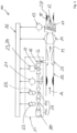
- FIG. 1 shows a schematic view of a first exemplary gas burner appliance 10.
- the gas burner appliance 10 comprises a combustion chamber 11 in which combustion of a gas/air mixture M having a defined mixing ratio of gas G and air A takes place during a regular combustion mode of the gas burner appliance 10, namely after a start-up of the gas burner appliance 10 and after successfully igniting the gas/air mixture M.
- the combustion of the gas/air mixture M results into flames 12 and into exhaust gas E.
- the flames 12 are monitored by a combustion quality sensor, preferably by a flame ionization sensor 13 providing as output signal an electrical flame ionization current.
- the flame ionization sensor 13 provides its output signal to a controller 26.
- the exhaust gas E emanates from the combustion chamber 11 through an exhaust pipe 28.
- the gas/air mixture M is provided to the combustion chamber 11 of the gas burner appliance 10 by mixing a flow of the air A with a flow of the gas G.
- a fan 14 sucks in air A flowing through an air duct 15 and gas G flowing through a gas duct 16.
- An electrical or electronic gas flow modulator 18 being configured to adjust the gas flow through the gas duct 16 and a gas safety valve unit 19 having preferably two gas safety valves 19a, 19b are assigned to the gas duct 16.
- the gas flow modulator 18 and the gas safety valves 19a, 19b are part of a gas armature 17 further comprising a sieve 20 and an electrical or electronic absolute pressure sensor 21.
- the sieve 20 and the electrical or electronic absolute pressure sensor 21 are both assigned to the gas duct 16.
- the absolute pressure sensor 21 provides its output signal to the controller 26.
- the electrical or electronic absolute pressure sensor 21, namely the measuring point 21a of the same, is positioned downstream of the second gas safety valve 19b of gas safety valve unit.
- the electrical or electronic absolute pressure sensor 21, namely the measuring point 21a of the same, is positioned downstream of gas safety valve unit 19 und upstream of the electrical or electronic gas flow modulator 18.
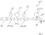
- the gas armature 17 of Figure 1 can be replaced by the gas armature 17 of Figure 2 .
- the electrical or electronic absolute pressure sensor 21, namely the measuring point 21a of the same is positioned downstream of the first gas safety valve 19a of the gas safety valve unit 19 and upstream of the second gas safety valve 19b of the gas safety valve unit 19.
- the gas safety valves 19a, 19b of the gas safety valve unit 19 are operated by electric coils 22 being part of the gas armature 17. In a regular combustion mode, the electric coils 22 are energized by the controller 26 to open the gas safety valves 19a, 19b. In burner-off phases the gas safety valves 19 are closed.
- each gas safety valve 19a, 19b is operated by one separate electric coil 22. With the use of separate electric coils 22 it is possible to open and close the gas safety valves 19a, 19b independently from each other. Alternatively, the gas safety valves 19a, 19b may be operated commonly by a common electric coil 22.
- the electrical or electronic gas flow modulator 18 is operated by a motor 23 also having an electric coil 24.
- the gas flow modulator 18 is an electric gas flow modulator 18 operated by the controller 26.
- the gas flow modulator 18 is in its closed position not gas tight.
- the gas/air mixture M having the defined mixing ratio of gas G and air A is provided to the combustion chamber 11 of the gas burner appliance 10.
- the gas/air mixture M is provided by mixing the air flow A provided by an air duct 15 with a gas flow G provided by a gas duct 16.
- the air flow and the gas flow become preferably mixed by a mixing device 25.
- the mixing device 25 may be a venturi nozzle.
- the quantity of the air flow A and thereby the quantity of the gas/air mixture flow M is adjusted by the fan 14, namely by the speed of the fan 14.
- the fan speed can be adjusted on basis of a nominal burner-load.
- a nominal fan speed of the fan 14 depends on the nominal burner load.
- the fan 14 is operated by the controller 26.
- the fan speed range of the fan 14 defines a modulation range of the gas burner appliance 10.
- a modulation of "1" means that the fan 14 is operated at maximum fan speed (100% of maximum fan speed) and thereby at a full-load of the gas burner appliance 10.
- a modulation of "2" means that the fan 14 is operated at 50% of the maximum fan speed and a modulation of "5" means that the fan 14 is operated at 20% of the maximum fan speed.
- the defined mixing ratio of gas G and air A within the gas/air mixture M and thereby the ⁇ -value of the gas/air mixture M is kept at a nominal value, preferably constant, over the entire modulation range of the gas burner appliance 10.
- Said defined mixing ratio of gas G and air A or said ⁇ -value of the gas/air mixture M is kept at a defined value over the modulation range of the gas burner appliance using the electrical or electronic gas flow modulator 18 of a gas armature 17 to keep the defined mixing ratio of gas and air and thereby the ⁇ -value preferably constant over the modulation range of the gas burner appliance.
- the control variable for the electric gas flow modulator 18 in order to keep the ⁇ -value constant is generated by the controller 26 on basis of the flame ionization current provided by the flame ionization sensor 13.
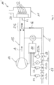
- Figures 3 a shows schematic view of other exemplary gas burner appliance 10'.
- identical reference numbers are used for identical parts. In order to avoid unnecessary repetitions, below only the differences of the gas burner appliances 10, 10' will be described.
- the constant mixing ratio of gas G and air A within the gas/air mixture M is controlled by the electrical or electronic gas flow modulator 18 on basis of a signal provided by an electric or electronic pressure sensor or flow meter 27 and not on basis of the flame ionization current provided by the flame ionization sensor 13.
- the electric or electronic sensor 27 may provide to the controller 26 an actual value corresponding to a pressure ratio between a gas pressure in a gas duct 16 and an air pressure in an air duct 15 or corresponding to a pressure ratio between the gas pressure in the gas duct 16 and the air pressure at the reference point, wherein the controller 26 may compare said actual value with a nominal value.
- the controller 26 may generate the control variable for the electric gas flow modulator 18 on basis of the control deviation between the actual value and the nominal value, wherein the gas flow modulator 18 may be operated on basis of this control variable to keep over the entire modulation range of the gas burner appliance 10 the defined mixing ratio of gas and air and thereby the ⁇ -value constant.
- the gas flow modulator 18 is in its closed position not gas-tight.
- the absolute pressure sensor 21 is positioned between the gas safety valve unit 19 and the gas flow modulator 18.
- the absolute pressure sensor 21, namely the measuring point 21a of the same may be positioned downstream of the first gas safety valve 19a and upstream of the second gas safety valve 19b.
- the present invention provides a method for operating such gas burner appliances 10, 10' to compensate at least for a fluctuating gas inlet pressure of the gas burner appliance 10, 10'.
- the gas burner appliance 10, 10' is operated to compensate for a fluctuating gas inlet pressure of the gas burner appliance 10, 10' by executing the following steps: Measure a first absolute pressure by the absolute pressure sensor 21 when at least the first gas safety valve 19a of the gas safety valve unit 19 is closed.
- the second gas safety valve 19b needs to be opened.
- both gas safety valve 19a, 19b may be closed.
- the first absolute pressure may be measured by the absolute pressure sensor 21 when at least the first gas safety valve 19a of the gas safety valve unit 19 is closed and when the fan 14 is stopped.
- the first absolute pressure may be measured by the absolute pressure sensor 21 when at least the first gas safety valve 19a of the gas safety valve unit 19 is closed and when the fan 14 is running, wherein then the pressure depending on the first absolute pressure is determined from the measured first absolute pressure and from of the fan speed.
- Said pressure depending on the first absolute pressure is preferably determined from the measured first absolute pressure and from of the fan speed of the fan 14 on basis of a first characteristic curve.
- the first characteristic curve may be empirically determined and may be stored within a memory unit of the controller 26.
- the second absolute pressure is measured by the absolute pressure sensor 21 when the gas safety valve unit 19 is opened and when the fan 14 is running.
- the pressure difference is preferably determined between the first absolute pressure or the pressure depending on the first absolute pressure and the second absolute pressure. Said pressure difference may be adapted into an adapted pressure difference as a function of the fan speed of the fan 14. The gas flow modulator 18 is then operated on basis of said adapted pressure difference to compensate for a fluctuating gas inlet pressure of the gas burner appliance 10, 10'.
- the pressure difference is preferably adapted into a said adapted pressure difference on basis of a second characteristic curve.
- the second characteristic curve may be empirically determined and may be stored within the memory unit of the controller 26.
- the following steps are executed: Measure the first absolute pressure by the absolute pressure sensor 21 when at least the first gas safety valve 19a of the gas safety valve unit 19 is closed.
- the pressure depending on the first absolute pressure may be determined from the measured first absolute pressure and from the fan speed, if the first absolute pressure is measured while the fan 14 is running.
- the first absolute pressure or the pressure depending on the first absolute pressure is stored within the memory unit of the controller 26.
- the gas safety valve unit 19 For the start-up of the gas burner appliance 10, 10', then open the gas safety valve unit 19, run the fan 14 at a defined fan speed, activate an ignition device (not shown) positioned with the combustion chamber 11 and measure continuously or at a defined sampling rate the second absolute pressure by the absolute pressure sensor 21 while increasing the opening position of the gas flow modulator 18.
- the opening position of the gas flow modulator 18 is increased to increase the content of the gas G within the gas/air mixture M provided to the combustion chamber 11 in order to provide an ignitable gas/air mixture M.
- the pressure difference between the stored first absolute pressure (if the first absolute pressure is measured while the fan 14 is not running) or the stored pressure depending on the first absolute pressure and the second absolute pressure (if the first absolute pressure is measured while the fan 14 is running) and the second absolute pressure. Adjust continuously or at the defined sampling rate the opening position of the gas flow modulator 18 dependent from said pressure difference.
- the pressure difference may be adapted into said adapted pressure difference as a function of the fan speed of the fan 14, wherein the gas flow modulator 18 may then be operated on basis of said adapted pressure difference to compensate for a fluctuating gas inlet pressure of the gas burner appliance 10, 10'. This provides an efficient and fast start-up of the gas burner appliance 10, 10'.
- the pressure difference may be adapted into said adapted pressure difference as a function of the fan speed of the fan 14, wherein the gas flow modulator 18 may then be operated on basis of said adapted pressure difference to compensate for a fluctuating gas inlet pressure of the gas burner appliance 10, 10'.
- the first absolute pressure may be adapted to compensate for fluctuating weather conditions on basis of an absolute pressure measured by an additional absolute pressure sensor (not shown) not being assigned the gas duct 16.
- an additional absolute pressure sensor (not shown) may be assigned to a circuit board of the controller 26.
- the first absolute pressure may be adapted to compensate for fluctuating weather conditions on basis of an absolute pressure received over the internet.
- the controller 26 may have an interface in order to receive data about the actual weather conditions and about the actual absolute air pressure over the internet.
- the first absolute pressure may be adapted to compensate for fluctuating weather conditions on basis of the first absolute pressure is adapted to compensate for fluctuating weather conditions by executing the following steps: During the start-up of the gas burner appliance 10, 10' measure the first and second absolute pressure and determine a first difference from the same and use said difference as offset value. After the start-up of the gas burner appliance 10, 10' determine continuously or at the defined sampling rate a second difference between the second absolute pressure and the offset value, filter said second difference by limiting the temporal gradient of said second difference to a maximum value and use the filtered second difference as adapted first absolute pressure.
- the invention further provides a gas burner appliance 10, 10' having the controller 26 being configured to operate the gas burner appliance 10, 10' according to the above method.
- the controller 26 is configured to compensate for a fluctuating gas inlet pressure of the gas burner appliance by executing at least the following steps: Measure a first absolute pressure by the absolute pressure sensor 21 when at least a first gas safety valve 19a of a gas safe-ty valve unit 19 is closed. Measure a second absolute pressure by the absolute pressure sensor 21 when the gas safety valve unit 19 is opened. Determine a pressure difference between the first absolute pressure or a pressure depending on the first absolute pressure and the second absolute pressure or a pressure depending on the second absolute pressure. Operate the gas flow modulator 18 dependent from said pressure difference.
- the invention allows to compensate at least for a fluctuating gas inlet pressure of the gas burner appliance 10, 10'.
- fluctuating weather conditions causing a fluctuating ambient air pressure may be compensated.
Landscapes
- Engineering & Computer Science (AREA)
- Chemical & Material Sciences (AREA)
- Combustion & Propulsion (AREA)
- Mechanical Engineering (AREA)
- General Engineering & Computer Science (AREA)
- Regulation And Control Of Combustion (AREA)
Claims (15)
- Verfahren zum Betreiben eines Gasbrennergeräts (10, 10'), wobei das Gasbrennergerät aufweist:eine Verbrennungskammer (11), die für die Verbrennung eines definierten Gas/Luft-Gemischs ausgestaltet ist,eine Mischvorrichtung (23), die dazu ausgestaltet ist, das Gas/Luft-Gemisch durch Mischen eines durch einen Luftkanal (15) bereitgestellten Luftstroms mit einem durch einen Gaskanal (16) bereitgestellten Gasstrom bereitzustellen,ein Gebläse (14), das dazu ausgestaltet ist, den Luftstrom oder den Strom des Gas/Luft-Gemischs bereitzustellen,eine dem Gaskanal (16) zugeordnete Gassicherheitsventileinheit (19), die zum Öffnen oder Schließen des Gaskanals (16) ausgestaltet ist,
wobei die Gassicherheitsventileinheit (19) ein erstes Gassicherheitsventil (19a) und ein zweites Gassicherheitsventil (19b), das stromabwärts des ersten Gassicherheitsventils (19a) angeordnet ist, aufweist,einen dem Gaskanal (16) zugeordneten Gasstrommodulator (18), der stromabwärts des zweiten Gassicherheitsventils (19b) angeordnet und dazu ausgestaltet ist, ein Mischungsverhältnis von Gas und Luft innerhalb des Gas/Luft-Gemischs auf einem definierten Wert zu halten,einen dem Gaskanal (16) zugeordneten elektrischen oder elektronischen Absolutdrucksensor (21), wobei der Absolutdrucksensor (21) entweder stromabwärts des ersten Gassicherheitsventils (19a) und stromabwärts des zweiten Gassicherheitsventils (19b) der Gassicherheitsventileinheit und stromaufwärts des Gasstrommodulators (18) angeordnet ist oder stromabwärts des ersten Gassicherheitsventils (19a) und stromaufwärts des zweiten Gassicherheitsventils (19b) angeordnet ist,wobei das Gasbrennergerät (10, 10') betrieben wird, um einen schwankenden Gaseintrittsdruck des Gasbrennergeräts (10, 10') durch Ausführen der folgenden Schritte zu kompensieren:Messen eines ersten Absolutdrucks durch den Absolutdrucksensor (21), wenn zumindest das erste Gassicherheitsventil (19a) der Gassicherheitsventileinheit (19) geschlossen ist, wobeiwenn der Absolutdrucksensor (21) stromabwärts des ersten Gassicherheitsventils (19a) und stromabwärts des zweiten Gassicherheitsventils (19b) angeordnet ist, das zweite Gassicherheitsventil (19b) geschlossen oder geöffnet wird,wenn der Absolutdrucksensor (21) stromabwärts des ersten Gassicherheitsventils (19a) und stromaufwärts des zweiten Gassicherheitsventils (19b) angeordnet ist, das zweite Gassicherheitsventil (19b) dann geöffnet wird,Messen eines zweiten Absolutdrucks durch den Absolutdrucksensor (21), wenn die Gassicherheitsventileinheit (19) geöffnet ist,Bestimmen einer Druckdifferenz zwischen dem ersten Absolutdruck oder einem vom ersten Absolutdruck abhängigen Druck und dem zweiten Absolutdruck oder einem vom zweiten Absolutdruck abhängigen Druck,Betreiben des Gasstrommodulators (18) in Abhängigkeit von der Druckdifferenz. - Verfahren nach Anspruch 1, wobei
der erste Absolutdruck durch den Absolutdrucksensor (21) gemessen wird, wenn zumindest das erste Gassicherheitsventil (19a) der Gassicherheitsventileinheit (19) geschlossen ist und wenn das Gebläse (14) stillsteht. - Verfahren nach Anspruch 1, wobei
der erste Absolutdruck durch den Absolutdrucksensor (21) gemessen wird, wenn zumindest das erste Gassicherheitsventil (19a) der Gassicherheitsventileinheit (19) geschlossen ist und wenn das Gebläse (14) läuft, wobei der vom ersten Absolutdruck abhängige Druck aus dem gemessenen ersten Absolutdruck und aus der Gebläsedrehzahl bestimmt wird. - Verfahren nach Anspruch 3, wobei
der vom ersten Absolutdruck abhängige Druck aus dem gemessenen ersten Absolutdruck und aus der Gebläsedrehzahl auf Basis einer ersten Kennlinie bestimmt wird. - Verfahren nach einem der Ansprüche 1 bis 4, wobei
der zweite Absolutdruck durch den Absolutdrucksensor (21) gemessen wird, wenn die Gassicherheitsventileinheit (19) geöffnet ist und wenn das Gebläse läuft. - Verfahren nach einem der Ansprüche 1 bis 5, wobei
die Druckdifferenz zwischen dem ersten Absolutdruck oder dem vom ersten Absolutdruck abhängigen Druck und dem zweiten Absolutdruck bestimmt wird. - Verfahren nach Anspruch 6, wobeidie Druckdifferenz in eine angepasste Druckdifferenz in Abhängigkeit von der Gebläsedrehzahl umgewandelt wird,der Gasstrommodulator (18) auf Grundlage der angepassten Druckdifferenz betrieben wird, um einen schwankenden Gaseintrittsdruck des Gasbrennergeräts zu kompensieren.
- Verfahren nach Anspruch 7, wobei
die Druckdifferenz auf Grundlage einer zweiten Kennlinie in die angepasste Druckdifferenz umgewandelt wird. - Verfahren nach einem der Ansprüche 1 bis 8, wobei
für eine Inbetriebnahme des Gasbrennergeräts (10, 10') die folgenden Schritte ausgeführt werden:Messen des ersten Absolutdrucks, wenn zumindest das erste Gassicherheitsventil (19a) der Gassicherheitsventileinheit (19) geschlossen ist,dann Öffnen der Gassicherheitsventileinheit (19), Betreiben des Gebläses (14) mit einer definierten Gebläsedrehzahl, Aktivieren einer Zündvorrichtung und kontinuierliches Messen, oder Messen mit einer definierten Abtastrate, des zweiten Absolutdrucks und gleichzeitiges Vergrößern der Öffnungsposition des Gasstrommodulators (18),kontinuierliches Bestimmen, oder Bestimmen mit der definierten Abtastrate, der Druckdifferenz,kontinuierliches Anpassen, oder Anpassen mit der definierten Abtastrate, der Öffnungsposition des Gasstrommodulators (18) in Abhängigkeit von der Druckdifferenz. - Verfahren nach einem der Ansprüche 1 bis 9, wobei
nach der Inbetriebnahme des Gasbrennergeräts (10, 10'), während ein Gas/Luft-Gemisch verbrannt wird, die folgenden Schritte ausgeführt werden:Bestimmen eines angepassten ersten Absolutdrucks auf Grundlage des ersten Absolutdrucks, um schwankende Witterungsbedingungen zu kompensieren,kontinuierliches Messen, oder Messen mit einer definierten Abtastrate, des zweiten Absolutdrucks,kontinuierliches Bestimmen, oder Bestimmen mit der definierten Abtastrate, der Druckdifferenz,kontinuierliches Anpassen, oder Anpassen mit der definierten Abtastrate, der Öffnungsposition des Gasstrommodulators (18) in Abhängigkeit von der Druckdifferenz. - Verfahren nach Anspruch 10, wobei
der angepasste erste Absolutdruck zum Kompensieren schwankender Witterungsbedingungen auf Grundlage eines Absolutdrucks bestimmt wird, der durch einen zusätzlichen Absolutdrucksensor gemessen wird, der dem Gaskanal (16) nicht zugeordnet ist. - Verfahren nach Anspruch 10, wobei
der angepasste erste Absolutdruck zum Kompensieren schwankender Witterungsbedingungen auf Grundlage eines über das Internet empfangenen Absolutdrucks bestimmt wird. - Verfahren nach Anspruch 10, wobei
der angepasste erste Absolutdruck zum Kompensieren schwankender Witterungsbedingungen durch Ausführen der folgenden Schritte bestimmt wird:während der Inbetriebnahme des Gasbrennergeräts (10, 10') Messen des ersten und des zweiten Absolutdrucks und daraus Bestimmen einer ersten Differenz und Verwenden dieser Differenz als Offsetwert,nach einer Inbetriebnahme des Gasbrennergeräts (10, 10') kontinuierliches Bestimmen, oder Bestimmen mit der definierten Abtastrate, einer zweiten Differenz zwischen dem zweiten Absolutdruck und dem Offsetwert, Filtern dieser zweiten Differenz durch Begrenzen des zeitlichen Gradienten dieser zweiten Differenz auf einen Maximalwert und Verwenden der gefilterten zweiten Differenz als angepassten ersten Absolutdruck. - Verfahren nach einem der Ansprüche 1 bis 9, wobei
nach der Inbetriebnahme des Gasbrennergeräts (10, 10'), während ein Gas/Luft-Gemisch verbrannt wird, die folgenden Schritte ausgeführt werden:kontinuierliches Messen, oder Messen mit einer definierten Abtastrate, des zweiten Absolutdrucks,kontinuierliches Bestimmen, oder Bestimmen mit der definierten Abtastrate, der Druckdifferenz,kontinuierliches Anpassen, oder Anpassen mit der definierten Abtastrate, der Öffnungsposition des Gasstrommodulators (18) in Abhängigkeit von der Druckdifferenz, und zwar in Abhängigkeit vom zeitlichen Gradienten der Druckdifferenz. - Gasbrennergerät (10, 10'), aufweisend ein Steuergerät (26) zum Betreiben des Gasbrennergeräts (10, 10'),
wobei das Steuergerät (26) dazu ausgestaltet ist, einen schwankenden Gaseintrittsdruck des Gasbrennergeräts (10, 10') durch Ausführen der folgenden Schritte zu kompensieren:Messen eines ersten Absolutdrucks durch den Absolutdrucksensor (21), wenn zumindest ein erstes Gassicherheitsventil (19a) einer Gassicherheitsventileinheit (19) geschlossen ist, wobei die Gassicherheitsventileinheit (19) ein zweites Gassicherheitsventil (19b) aufweist, das stromabwärts des ersten Gassicherheitsventils (19a) angeordnet ist, wobeiwenn der Absolutdrucksensor (21) stromabwärts des ersten Gassicherheitsventils (19a) und stromabwärts des zweiten Gassicherheitsventils (19b) und stromaufwärts eines Gasstrommodulators (18) angeordnet ist, das zweite Gassicherheitsventil (19b) geschlossen oder geöffnet wird,wenn der Absolutdrucksensor (21) stromabwärts des ersten Gassicherheitsventils (19a) und stromaufwärts des zweiten Gassicherheitsventils (19b) angeordnet ist, das zweite Gassicherheitsventil (19b) dann geöffnet wird,Messen eines zweiten Absolutdrucks durch den Absolutdrucksensor (21), wenn die Gassicherheitsventileinheit (19) geöffnet ist,Bestimmen einer Druckdifferenz zwischen dem ersten Absolutdruck oder einem vom ersten Absolutdruck abhängigen Druck und dem zweiten Absolutdruck oder einem vom zweiten Absolutdruck abhängigen Druck,Betreiben des Gasstrommodulators (18), der stromabwärts des zweiten Gassicherheitsventils (19b) angeordnet ist, in Abhängigkeit von der Druckdifferenz.
Priority Applications (4)
| Application Number | Priority Date | Filing Date | Title |
|---|---|---|---|
| EP21185474.0A EP4119846B1 (de) | 2021-07-14 | 2021-07-14 | Verfahren und steuergerät zum betrieb eines gasbrennergeräts |
| CN202280062436.6A CN117980660A (zh) | 2021-07-14 | 2022-07-11 | 用于操作燃气燃烧器器具的方法和控制器 |
| PCT/EP2022/069264 WO2023285352A1 (en) | 2021-07-14 | 2022-07-11 | Method and controller for operating a gas burner appliance |
| US18/578,910 US20240337385A1 (en) | 2021-07-14 | 2022-07-11 | Method and Controller for Operating a Gas Burner Appliance |
Applications Claiming Priority (1)
| Application Number | Priority Date | Filing Date | Title |
|---|---|---|---|
| EP21185474.0A EP4119846B1 (de) | 2021-07-14 | 2021-07-14 | Verfahren und steuergerät zum betrieb eines gasbrennergeräts |
Publications (2)
| Publication Number | Publication Date |
|---|---|
| EP4119846A1 EP4119846A1 (de) | 2023-01-18 |
| EP4119846B1 true EP4119846B1 (de) | 2024-12-11 |
Family
ID=77042705
Family Applications (1)
| Application Number | Title | Priority Date | Filing Date |
|---|---|---|---|
| EP21185474.0A Active EP4119846B1 (de) | 2021-07-14 | 2021-07-14 | Verfahren und steuergerät zum betrieb eines gasbrennergeräts |
Country Status (4)
| Country | Link |
|---|---|
| US (1) | US20240337385A1 (de) |
| EP (1) | EP4119846B1 (de) |
| CN (1) | CN117980660A (de) |
| WO (1) | WO2023285352A1 (de) |
Family Cites Families (8)
| Publication number | Priority date | Publication date | Assignee | Title |
|---|---|---|---|---|
| DE19824521B4 (de) | 1998-06-02 | 2004-12-23 | Honeywell B.V. | Regeleinrichtung für Gasbrenner |
| FR2818746B1 (fr) * | 2000-12-26 | 2003-03-28 | Gaz De France | Procede et dispositif d'evaluation de l'indice de wobbe d'un gaz combustible |
| WO2005024302A1 (en) | 2003-09-08 | 2005-03-17 | Sit La Precisa S.P.A. | A system for controlling the delivery of a fuel gas to a burner apparatus |
| JP4850163B2 (ja) | 2007-10-16 | 2012-01-11 | 中国電力株式会社 | ガス燃焼装置 |
| AT510075B1 (de) | 2010-07-08 | 2012-05-15 | Vaillant Group Austria Gmbh | Verfahren zur kalibrierung einer einrichtung zum regeln des brenngas-luft-verhältnisses eines brenngasbetriebenen brenners |
| US9846440B2 (en) * | 2011-12-15 | 2017-12-19 | Honeywell International Inc. | Valve controller configured to estimate fuel comsumption |
| EP2667097B1 (de) | 2012-05-24 | 2018-03-07 | Honeywell Technologies Sarl | Verfahren zum Betrieb eines Gasbrenners |
| JP2017116382A (ja) * | 2015-12-24 | 2017-06-29 | 三浦工業株式会社 | ガス漏れ検出装置及びガス漏れ検出方法 |
-
2021
- 2021-07-14 EP EP21185474.0A patent/EP4119846B1/de active Active
-
2022
- 2022-07-11 CN CN202280062436.6A patent/CN117980660A/zh active Pending
- 2022-07-11 US US18/578,910 patent/US20240337385A1/en active Pending
- 2022-07-11 WO PCT/EP2022/069264 patent/WO2023285352A1/en not_active Ceased
Also Published As
| Publication number | Publication date |
|---|---|
| EP4119846A1 (de) | 2023-01-18 |
| US20240337385A1 (en) | 2024-10-10 |
| CN117980660A (zh) | 2024-05-03 |
| WO2023285352A1 (en) | 2023-01-19 |
Similar Documents
| Publication | Publication Date | Title |
|---|---|---|
| EP3228936B1 (de) | Verfahren zum betrieb eines gasbrennergeräts | |
| EP2667097B1 (de) | Verfahren zum Betrieb eines Gasbrenners | |
| CA2372842A1 (en) | Regulating device for gas burners | |
| US6019593A (en) | Integrated gas burner assembly | |
| EP2685169B1 (de) | Verfahren zum Betrieb eines Gasbrenners | |
| CA1240916A (en) | Gas burner | |
| EP3913285B1 (de) | Verfahren und steuergerät zum betrieb eines gasbrennergeräts | |
| EP2631541B1 (de) | Verfahren zum Betrieb eines Gasbrenners | |
| EP4119846B1 (de) | Verfahren und steuergerät zum betrieb eines gasbrennergeräts | |
| EP4119845B1 (de) | Verfahren und steuergerät zum betrieb eines gasbrennergeräts | |
| EP2685168B1 (de) | Verfahren zum Betrieb eines Gasbrenners | |
| EP4092325B1 (de) | Verfahren und steuergerät zum betrieb eines gasbrennergeräts | |
| EP2685167B1 (de) | Verfahren zum Betrieb eines Gasbrenners | |
| EP4155609B1 (de) | Verfahren und steuergerät zum betrieb eines gasbrennergeräts | |
| EP4033148B1 (de) | Verfahren und steuergerät zum betrieb eines gasbrennergeräts | |
| EP3869101B1 (de) | Flammenüberwachungsvorrichtung für ein gasbrennergerät und gasbrennergerät | |
| US11287131B2 (en) | Method for operating a gas burner appliance |
Legal Events
| Date | Code | Title | Description |
|---|---|---|---|
| PUAI | Public reference made under article 153(3) epc to a published international application that has entered the european phase |
Free format text: ORIGINAL CODE: 0009012 |
|
| STAA | Information on the status of an ep patent application or granted ep patent |
Free format text: STATUS: THE APPLICATION HAS BEEN PUBLISHED |
|
| AK | Designated contracting states |
Kind code of ref document: A1 Designated state(s): AL AT BE BG CH CY CZ DE DK EE ES FI FR GB GR HR HU IE IS IT LI LT LU LV MC MK MT NL NO PL PT RO RS SE SI SK SM TR |
|
| STAA | Information on the status of an ep patent application or granted ep patent |
Free format text: STATUS: REQUEST FOR EXAMINATION WAS MADE |
|
| 17P | Request for examination filed |
Effective date: 20230717 |
|
| RBV | Designated contracting states (corrected) |
Designated state(s): AL AT BE BG CH CY CZ DE DK EE ES FI FR GB GR HR HU IE IS IT LI LT LU LV MC MK MT NL NO PL PT RO RS SE SI SK SM TR |
|
| P01 | Opt-out of the competence of the unified patent court (upc) registered |
Effective date: 20230827 |
|
| RIC1 | Information provided on ipc code assigned before grant |
Ipc: F23N 5/18 20060101ALN20240322BHEP Ipc: F23N 5/24 20060101ALI20240322BHEP Ipc: F23N 5/12 20060101ALI20240322BHEP Ipc: F23N 1/02 20060101AFI20240322BHEP |
|
| GRAP | Despatch of communication of intention to grant a patent |
Free format text: ORIGINAL CODE: EPIDOSNIGR1 |
|
| STAA | Information on the status of an ep patent application or granted ep patent |
Free format text: STATUS: GRANT OF PATENT IS INTENDED |
|
| RIC1 | Information provided on ipc code assigned before grant |
Ipc: F23N 5/18 20060101ALN20240419BHEP Ipc: F23N 5/24 20060101ALI20240419BHEP Ipc: F23N 5/12 20060101ALI20240419BHEP Ipc: F23N 1/02 20060101AFI20240419BHEP |
|
| INTG | Intention to grant announced |
Effective date: 20240514 |
|
| GRAJ | Information related to disapproval of communication of intention to grant by the applicant or resumption of examination proceedings by the epo deleted |
Free format text: ORIGINAL CODE: EPIDOSDIGR1 |
|
| STAA | Information on the status of an ep patent application or granted ep patent |
Free format text: STATUS: REQUEST FOR EXAMINATION WAS MADE |
|
| GRAS | Grant fee paid |
Free format text: ORIGINAL CODE: EPIDOSNIGR3 |
|
| STAA | Information on the status of an ep patent application or granted ep patent |
Free format text: STATUS: GRANT OF PATENT IS INTENDED |
|
| GRAP | Despatch of communication of intention to grant a patent |
Free format text: ORIGINAL CODE: EPIDOSNIGR1 |
|
| INTC | Intention to grant announced (deleted) | ||
| RIC1 | Information provided on ipc code assigned before grant |
Ipc: F23N 5/18 20060101ALN20240911BHEP Ipc: F23N 5/24 20060101ALI20240911BHEP Ipc: F23N 5/12 20060101ALI20240911BHEP Ipc: F23N 1/02 20060101AFI20240911BHEP |
|
| INTG | Intention to grant announced |
Effective date: 20240925 |
|
| GRAA | (expected) grant |
Free format text: ORIGINAL CODE: 0009210 |
|
| STAA | Information on the status of an ep patent application or granted ep patent |
Free format text: STATUS: THE PATENT HAS BEEN GRANTED |
|
| AK | Designated contracting states |
Kind code of ref document: B1 Designated state(s): AL AT BE BG CH CY CZ DE DK EE ES FI FR GB GR HR HU IE IS IT LI LT LU LV MC MK MT NL NO PL PT RO RS SE SI SK SM TR |
|
| REG | Reference to a national code |
Ref country code: GB Ref legal event code: FG4D |
|
| REG | Reference to a national code |
Ref country code: CH Ref legal event code: EP |
|
| REG | Reference to a national code |
Ref country code: DE Ref legal event code: R096 Ref document number: 602021023153 Country of ref document: DE |
|
| REG | Reference to a national code |
Ref country code: IE Ref legal event code: FG4D |
|
| REG | Reference to a national code |
Ref country code: NL Ref legal event code: FP |
|
| REG | Reference to a national code |
Ref country code: LT Ref legal event code: MG9D |
|
| PG25 | Lapsed in a contracting state [announced via postgrant information from national office to epo] |
Ref country code: HR Free format text: LAPSE BECAUSE OF FAILURE TO SUBMIT A TRANSLATION OF THE DESCRIPTION OR TO PAY THE FEE WITHIN THE PRESCRIBED TIME-LIMIT Effective date: 20241211 |
|
| PG25 | Lapsed in a contracting state [announced via postgrant information from national office to epo] |
Ref country code: FI Free format text: LAPSE BECAUSE OF FAILURE TO SUBMIT A TRANSLATION OF THE DESCRIPTION OR TO PAY THE FEE WITHIN THE PRESCRIBED TIME-LIMIT Effective date: 20241211 |
|
| PG25 | Lapsed in a contracting state [announced via postgrant information from national office to epo] |
Ref country code: BG Free format text: LAPSE BECAUSE OF FAILURE TO SUBMIT A TRANSLATION OF THE DESCRIPTION OR TO PAY THE FEE WITHIN THE PRESCRIBED TIME-LIMIT Effective date: 20241211 |
|
| PG25 | Lapsed in a contracting state [announced via postgrant information from national office to epo] |
Ref country code: ES Free format text: LAPSE BECAUSE OF FAILURE TO SUBMIT A TRANSLATION OF THE DESCRIPTION OR TO PAY THE FEE WITHIN THE PRESCRIBED TIME-LIMIT Effective date: 20241211 |
|
| PG25 | Lapsed in a contracting state [announced via postgrant information from national office to epo] |
Ref country code: NO Free format text: LAPSE BECAUSE OF FAILURE TO SUBMIT A TRANSLATION OF THE DESCRIPTION OR TO PAY THE FEE WITHIN THE PRESCRIBED TIME-LIMIT Effective date: 20250311 |
|
| PG25 | Lapsed in a contracting state [announced via postgrant information from national office to epo] |
Ref country code: GR Free format text: LAPSE BECAUSE OF FAILURE TO SUBMIT A TRANSLATION OF THE DESCRIPTION OR TO PAY THE FEE WITHIN THE PRESCRIBED TIME-LIMIT Effective date: 20250312 Ref country code: LV Free format text: LAPSE BECAUSE OF FAILURE TO SUBMIT A TRANSLATION OF THE DESCRIPTION OR TO PAY THE FEE WITHIN THE PRESCRIBED TIME-LIMIT Effective date: 20241211 |
|
| PG25 | Lapsed in a contracting state [announced via postgrant information from national office to epo] |
Ref country code: RS Free format text: LAPSE BECAUSE OF FAILURE TO SUBMIT A TRANSLATION OF THE DESCRIPTION OR TO PAY THE FEE WITHIN THE PRESCRIBED TIME-LIMIT Effective date: 20250311 |
|
| REG | Reference to a national code |
Ref country code: AT Ref legal event code: MK05 Ref document number: 1750635 Country of ref document: AT Kind code of ref document: T Effective date: 20241211 |
|
| PG25 | Lapsed in a contracting state [announced via postgrant information from national office to epo] |
Ref country code: SM Free format text: LAPSE BECAUSE OF FAILURE TO SUBMIT A TRANSLATION OF THE DESCRIPTION OR TO PAY THE FEE WITHIN THE PRESCRIBED TIME-LIMIT Effective date: 20241211 |
|
| PG25 | Lapsed in a contracting state [announced via postgrant information from national office to epo] |
Ref country code: PL Free format text: LAPSE BECAUSE OF FAILURE TO SUBMIT A TRANSLATION OF THE DESCRIPTION OR TO PAY THE FEE WITHIN THE PRESCRIBED TIME-LIMIT Effective date: 20241211 |
|
| PG25 | Lapsed in a contracting state [announced via postgrant information from national office to epo] |
Ref country code: IS Free format text: LAPSE BECAUSE OF FAILURE TO SUBMIT A TRANSLATION OF THE DESCRIPTION OR TO PAY THE FEE WITHIN THE PRESCRIBED TIME-LIMIT Effective date: 20250411 |
|
| PG25 | Lapsed in a contracting state [announced via postgrant information from national office to epo] |
Ref country code: PT Free format text: LAPSE BECAUSE OF FAILURE TO SUBMIT A TRANSLATION OF THE DESCRIPTION OR TO PAY THE FEE WITHIN THE PRESCRIBED TIME-LIMIT Effective date: 20250411 |
|
| PG25 | Lapsed in a contracting state [announced via postgrant information from national office to epo] |
Ref country code: EE Free format text: LAPSE BECAUSE OF FAILURE TO SUBMIT A TRANSLATION OF THE DESCRIPTION OR TO PAY THE FEE WITHIN THE PRESCRIBED TIME-LIMIT Effective date: 20241211 |
|
| PG25 | Lapsed in a contracting state [announced via postgrant information from national office to epo] |
Ref country code: RO Free format text: LAPSE BECAUSE OF FAILURE TO SUBMIT A TRANSLATION OF THE DESCRIPTION OR TO PAY THE FEE WITHIN THE PRESCRIBED TIME-LIMIT Effective date: 20241211 Ref country code: AT Free format text: LAPSE BECAUSE OF FAILURE TO SUBMIT A TRANSLATION OF THE DESCRIPTION OR TO PAY THE FEE WITHIN THE PRESCRIBED TIME-LIMIT Effective date: 20241211 |
|
| PG25 | Lapsed in a contracting state [announced via postgrant information from national office to epo] |
Ref country code: SK Free format text: LAPSE BECAUSE OF FAILURE TO SUBMIT A TRANSLATION OF THE DESCRIPTION OR TO PAY THE FEE WITHIN THE PRESCRIBED TIME-LIMIT Effective date: 20241211 |
|
| PG25 | Lapsed in a contracting state [announced via postgrant information from national office to epo] |
Ref country code: CZ Free format text: LAPSE BECAUSE OF FAILURE TO SUBMIT A TRANSLATION OF THE DESCRIPTION OR TO PAY THE FEE WITHIN THE PRESCRIBED TIME-LIMIT Effective date: 20241211 |
|
| PGFP | Annual fee paid to national office [announced via postgrant information from national office to epo] |
Ref country code: NL Payment date: 20250724 Year of fee payment: 5 |
|
| PG25 | Lapsed in a contracting state [announced via postgrant information from national office to epo] |
Ref country code: SE Free format text: LAPSE BECAUSE OF FAILURE TO SUBMIT A TRANSLATION OF THE DESCRIPTION OR TO PAY THE FEE WITHIN THE PRESCRIBED TIME-LIMIT Effective date: 20241211 |
|
| REG | Reference to a national code |
Ref country code: DE Ref legal event code: R097 Ref document number: 602021023153 Country of ref document: DE |
|
| PG25 | Lapsed in a contracting state [announced via postgrant information from national office to epo] |
Ref country code: DK Free format text: LAPSE BECAUSE OF FAILURE TO SUBMIT A TRANSLATION OF THE DESCRIPTION OR TO PAY THE FEE WITHIN THE PRESCRIBED TIME-LIMIT Effective date: 20241211 |
|
| PGFP | Annual fee paid to national office [announced via postgrant information from national office to epo] |
Ref country code: DE Payment date: 20250827 Year of fee payment: 5 |
|
| PGFP | Annual fee paid to national office [announced via postgrant information from national office to epo] |
Ref country code: TR Payment date: 20250702 Year of fee payment: 5 Ref country code: IT Payment date: 20250721 Year of fee payment: 5 |
|
| PGFP | Annual fee paid to national office [announced via postgrant information from national office to epo] |
Ref country code: GB Payment date: 20250722 Year of fee payment: 5 |
|
| PLBE | No opposition filed within time limit |
Free format text: ORIGINAL CODE: 0009261 |
|
| STAA | Information on the status of an ep patent application or granted ep patent |
Free format text: STATUS: NO OPPOSITION FILED WITHIN TIME LIMIT |
|
| PGFP | Annual fee paid to national office [announced via postgrant information from national office to epo] |
Ref country code: FR Payment date: 20250725 Year of fee payment: 5 |
|
| 26N | No opposition filed |
Effective date: 20250912 |