EP4119508B1 - Granulares schlammreaktor-system mit einem externen abscheider - Google Patents
Granulares schlammreaktor-system mit einem externen abscheider Download PDFInfo
- Publication number
- EP4119508B1 EP4119508B1 EP22192674.4A EP22192674A EP4119508B1 EP 4119508 B1 EP4119508 B1 EP 4119508B1 EP 22192674 A EP22192674 A EP 22192674A EP 4119508 B1 EP4119508 B1 EP 4119508B1
- Authority
- EP
- European Patent Office
- Prior art keywords
- bioreactor
- fluid
- biogas
- separator
- conduit
- Prior art date
- Legal status (The legal status is an assumption and is not a legal conclusion. Google has not performed a legal analysis and makes no representation as to the accuracy of the status listed.)
- Active
Links
Images
Classifications
-
- C—CHEMISTRY; METALLURGY
- C02—TREATMENT OF WATER, WASTE WATER, SEWAGE, OR SLUDGE
- C02F—TREATMENT OF WATER, WASTE WATER, SEWAGE, OR SLUDGE
- C02F3/00—Biological treatment of water, waste water, or sewage
- C02F3/28—Anaerobic digestion processes
- C02F3/2846—Anaerobic digestion processes using upflow anaerobic sludge blanket [UASB] reactors
-
- C—CHEMISTRY; METALLURGY
- C02—TREATMENT OF WATER, WASTE WATER, SEWAGE, OR SLUDGE
- C02F—TREATMENT OF WATER, WASTE WATER, SEWAGE, OR SLUDGE
- C02F1/00—Treatment of water, waste water, or sewage
- C02F1/20—Treatment of water, waste water, or sewage by degassing, i.e. liberation of dissolved gases
-
- C—CHEMISTRY; METALLURGY
- C02—TREATMENT OF WATER, WASTE WATER, SEWAGE, OR SLUDGE
- C02F—TREATMENT OF WATER, WASTE WATER, SEWAGE, OR SLUDGE
- C02F1/00—Treatment of water, waste water, or sewage
- C02F1/66—Treatment of water, waste water, or sewage by neutralisation; pH adjustment
-
- C—CHEMISTRY; METALLURGY
- C02—TREATMENT OF WATER, WASTE WATER, SEWAGE, OR SLUDGE
- C02F—TREATMENT OF WATER, WASTE WATER, SEWAGE, OR SLUDGE
- C02F3/00—Biological treatment of water, waste water, or sewage
- C02F3/28—Anaerobic digestion processes
- C02F3/2866—Particular arrangements for anaerobic reactors
- C02F3/2893—Particular arrangements for anaerobic reactors with biogas recycling
-
- C—CHEMISTRY; METALLURGY
- C12—BIOCHEMISTRY; BEER; SPIRITS; WINE; VINEGAR; MICROBIOLOGY; ENZYMOLOGY; MUTATION OR GENETIC ENGINEERING
- C12M—APPARATUS FOR ENZYMOLOGY OR MICROBIOLOGY; APPARATUS FOR CULTURING MICROORGANISMS FOR PRODUCING BIOMASS, FOR GROWING CELLS OR FOR OBTAINING FERMENTATION OR METABOLIC PRODUCTS, i.e. BIOREACTORS OR FERMENTERS
- C12M21/00—Bioreactors or fermenters specially adapted for specific uses
- C12M21/04—Bioreactors or fermenters specially adapted for specific uses for producing gas, e.g. biogas
-
- C—CHEMISTRY; METALLURGY
- C12—BIOCHEMISTRY; BEER; SPIRITS; WINE; VINEGAR; MICROBIOLOGY; ENZYMOLOGY; MUTATION OR GENETIC ENGINEERING
- C12M—APPARATUS FOR ENZYMOLOGY OR MICROBIOLOGY; APPARATUS FOR CULTURING MICROORGANISMS FOR PRODUCING BIOMASS, FOR GROWING CELLS OR FOR OBTAINING FERMENTATION OR METABOLIC PRODUCTS, i.e. BIOREACTORS OR FERMENTERS
- C12M29/00—Means for introduction, extraction or recirculation of materials, e.g. pumps
- C12M29/18—External loop; Means for reintroduction of fermented biomass or liquid percolate
-
- C—CHEMISTRY; METALLURGY
- C02—TREATMENT OF WATER, WASTE WATER, SEWAGE, OR SLUDGE
- C02F—TREATMENT OF WATER, WASTE WATER, SEWAGE, OR SLUDGE
- C02F2103/00—Nature of the water, waste water, sewage or sludge to be treated
- C02F2103/26—Nature of the water, waste water, sewage or sludge to be treated from the processing of plants or parts thereof
- C02F2103/28—Nature of the water, waste water, sewage or sludge to be treated from the processing of plants or parts thereof from the paper or cellulose industry
-
- C—CHEMISTRY; METALLURGY
- C02—TREATMENT OF WATER, WASTE WATER, SEWAGE, OR SLUDGE
- C02F—TREATMENT OF WATER, WASTE WATER, SEWAGE, OR SLUDGE
- C02F2103/00—Nature of the water, waste water, sewage or sludge to be treated
- C02F2103/32—Nature of the water, waste water, sewage or sludge to be treated from the food or foodstuff industry, e.g. brewery waste waters
- C02F2103/325—Nature of the water, waste water, sewage or sludge to be treated from the food or foodstuff industry, e.g. brewery waste waters from processes relating to the production of wine products
-
- C—CHEMISTRY; METALLURGY
- C02—TREATMENT OF WATER, WASTE WATER, SEWAGE, OR SLUDGE
- C02F—TREATMENT OF WATER, WASTE WATER, SEWAGE, OR SLUDGE
- C02F2103/00—Nature of the water, waste water, sewage or sludge to be treated
- C02F2103/32—Nature of the water, waste water, sewage or sludge to be treated from the food or foodstuff industry, e.g. brewery waste waters
- C02F2103/327—Nature of the water, waste water, sewage or sludge to be treated from the food or foodstuff industry, e.g. brewery waste waters from processes relating to the production of dairy products
-
- C—CHEMISTRY; METALLURGY
- C02—TREATMENT OF WATER, WASTE WATER, SEWAGE, OR SLUDGE
- C02F—TREATMENT OF WATER, WASTE WATER, SEWAGE, OR SLUDGE
- C02F2103/00—Nature of the water, waste water, sewage or sludge to be treated
- C02F2103/34—Nature of the water, waste water, sewage or sludge to be treated from industrial activities not provided for in groups C02F2103/12 - C02F2103/32
- C02F2103/36—Nature of the water, waste water, sewage or sludge to be treated from industrial activities not provided for in groups C02F2103/12 - C02F2103/32 from the manufacture of organic compounds
- C02F2103/365—Nature of the water, waste water, sewage or sludge to be treated from industrial activities not provided for in groups C02F2103/12 - C02F2103/32 from the manufacture of organic compounds from petrochemical industry (e.g. refineries)
-
- C—CHEMISTRY; METALLURGY
- C02—TREATMENT OF WATER, WASTE WATER, SEWAGE, OR SLUDGE
- C02F—TREATMENT OF WATER, WASTE WATER, SEWAGE, OR SLUDGE
- C02F2203/00—Apparatus and plants for the biological treatment of water, waste water or sewage
- C02F2203/002—Apparatus and plants for the biological treatment of water, waste water or sewage comprising an initial buffer container
-
- C—CHEMISTRY; METALLURGY
- C02—TREATMENT OF WATER, WASTE WATER, SEWAGE, OR SLUDGE
- C02F—TREATMENT OF WATER, WASTE WATER, SEWAGE, OR SLUDGE
- C02F2203/00—Apparatus and plants for the biological treatment of water, waste water or sewage
- C02F2203/006—Apparatus and plants for the biological treatment of water, waste water or sewage details of construction, e.g. specially adapted seals, modules, connections
-
- C—CHEMISTRY; METALLURGY
- C02—TREATMENT OF WATER, WASTE WATER, SEWAGE, OR SLUDGE
- C02F—TREATMENT OF WATER, WASTE WATER, SEWAGE, OR SLUDGE
- C02F2209/00—Controlling or monitoring parameters in water treatment
- C02F2209/02—Temperature
-
- C—CHEMISTRY; METALLURGY
- C02—TREATMENT OF WATER, WASTE WATER, SEWAGE, OR SLUDGE
- C02F—TREATMENT OF WATER, WASTE WATER, SEWAGE, OR SLUDGE
- C02F2209/00—Controlling or monitoring parameters in water treatment
- C02F2209/06—Controlling or monitoring parameters in water treatment pH
-
- C—CHEMISTRY; METALLURGY
- C02—TREATMENT OF WATER, WASTE WATER, SEWAGE, OR SLUDGE
- C02F—TREATMENT OF WATER, WASTE WATER, SEWAGE, OR SLUDGE
- C02F2301/00—General aspects of water treatment
- C02F2301/04—Flow arrangements
- C02F2301/046—Recirculation with an external loop
-
- C—CHEMISTRY; METALLURGY
- C02—TREATMENT OF WATER, WASTE WATER, SEWAGE, OR SLUDGE
- C02F—TREATMENT OF WATER, WASTE WATER, SEWAGE, OR SLUDGE
- C02F2301/00—General aspects of water treatment
- C02F2301/10—Temperature conditions for biological treatment
-
- Y—GENERAL TAGGING OF NEW TECHNOLOGICAL DEVELOPMENTS; GENERAL TAGGING OF CROSS-SECTIONAL TECHNOLOGIES SPANNING OVER SEVERAL SECTIONS OF THE IPC; TECHNICAL SUBJECTS COVERED BY FORMER USPC CROSS-REFERENCE ART COLLECTIONS [XRACs] AND DIGESTS
- Y02—TECHNOLOGIES OR APPLICATIONS FOR MITIGATION OR ADAPTATION AGAINST CLIMATE CHANGE
- Y02E—REDUCTION OF GREENHOUSE GAS [GHG] EMISSIONS, RELATED TO ENERGY GENERATION, TRANSMISSION OR DISTRIBUTION
- Y02E50/00—Technologies for the production of fuel of non-fossil origin
- Y02E50/30—Fuel from waste, e.g. synthetic alcohol or diesel
Definitions
- the invention relates to a method for treating an aqueous fluid, whereby biogas is produced in an installation comprising a bioreactor.
- the invention further relates to an installation suitable for carrying out such a method.
- Biological treatment of aqueous fluids uses active biomass (microorganisms, such as bacteria and/or archaea) to convert the pollutants (organic substances) to harmless components.
- active biomass microorganisms, such as bacteria and/or archaea
- anaerobic treatment without oxygen
- a consortia of anaerobic micro-organisms convert pollutants substantially to biogas.
- Anaerobic sludge bed reactor systems utilise anaerobic microorganisms to convert pollutants in aqueous fluids to biogas. These anaerobic bacteria mainly grow in aggregates, often referred to as granular biomass. The systems are often characterised by low net biomass production (typically 2-4 % of converted COD) as a result of the low net yield of anaerobic microorganisms involved.
- the method of retaining biomass in anaerobic treatment reactors can be done in various ways.
- the immobilization of biomass on a fixed or mobile carrier is one method to uncouple liquid retention time from biomass retention time.
- a better and preferred method however is to make use of mainly granulated biomass as applied in Upflow Anaerobic Sludge Blanket (UASB) reactors, Granular Sludge Bed reactors and IC reactors, see e.g. WO 2007/078195 , Frankin R.J. (2001). Full scale experiences with anaerobic treatment of industrial wastewater. Wat Sci. Tech., 44(8), 1-6 ) .
- Granular sludge bed (GSB) reactors such as Expanded Granular Sludge Bed (EGSB) reactors are commonly used reactors for the treatment of wastewater of for example the food processing and beverages industries, distilleries, pharmaceutical industries and pulp and paper mills.
- GBSB Expanded Granular Sludge Bed
- Such wastewater typically contains large amounts of organic pollutants that need to be removed before the water can be reused or discarded.
- wastewater is introduced into a lower part of an upflow bioreactor. Subsequently the water flows upwards through a granular sludge bed that comprises microorganisms which breakdown organic waste, present in the wastewater, whereby biogas - in particular methane and carbon dioxide - is formed which methane can in turn be used as a green energy source, for example to provide energy.
- a granular sludge bed that comprises microorganisms which breakdown organic waste, present in the wastewater, whereby biogas - in particular methane and carbon dioxide - is formed which methane can in turn be used as a green energy source, for example to provide energy.
- settling behavior of the biomass is the settling behavior of the biomass.
- Good settling behavior of the granules is necessary to achieve efficient separation of the phases.
- Settling of the granules is influenced by several factors, such as the hydraulics or fluid dynamics (liquid and gas) inside the reactor and/or the presence and design of a three phase separator device inside the reactor (turbulent and laminar flows, turbulence and upflow velocities).
- settling behavior can depend on the composition of the sludge granule, such as the biomass content, and/or mineral fraction.
- sludge granules with a high inert fraction could settle faster, but its degradation activity could be lower or any degradation activity could even be absent.
- inert sludge granules have the risk of not being able to expand and/or recirculated as a consequence of the biogas production and/or flow recirculation.
- they will have a tendency to remain at the bottom of the reactor, thereby blocking the sludge extraction ports and causing major issues of operation.
- the settling behavior of the granules is affected by the presence of gas inside the granules.
- Biomass located at the bottom of the reactor is subject to a higher pressure than that at the top of the reactor due to the great height that GSB systems, in particular EGSB systems may have, typically between 15 m and 25 m, and consequently the pressure caused by the water column, which is typically 1.5-2.5 bars.
- the gas inside the granules at the bottom of the reactor is compressed, resulting in a higher density of the granules, and therefore the granules settles faster.
- separating devices such as settlers are valuable tools towards achieving an improved separation of different phases and thereby enhancing the overall efficiency of the wastewater treatment process.
- Efficient separation of the phases may further be enhanced by creating particular flows inside of the reactor that aid for example the settleability of biomass (by pushing the solids downward).
- Such flows may be introduced by the separation systems such as the tilted plates in internal settlers, may be caused by the solubility of carbon dioxide in water creating turbulence or may be caused by the mere movement of the phases due to a difference in density, e.g. sludge tends to move downwards by gravity, whereas biogas flows upwards.
- EGSB reactor An example of an EGSB reactor is described in WO 2007/078195 . Further known is the BIOTHANE Biobed Advanced EGSB.
- This reactor has a three-phase separator, in a bioreactor and further comprises a conditioning tank.
- a tilted plate settler TPS
- a mammoth flow effect is created due to a difference in pressure beneath the tilted plate with respect to the top part of the plate, enabling a better separation of biogas and directing the settled biomass downwards.
- EP 1 134 194 A2 relates to an installation and process for biomass retention in bioreactors, in particular in anaerobic sludge bed reactors.
- the process may be carried out in an comprising an upflow bioreactor and an external separator.
- EP 2 065 344 A1 relates to a purifier comprising a fermentation chamber, a settling device fitted above the fermentation chamber (e.g. claim 13) and a method for anaerobic or aerobic water purification, using the settling device wherein gas and particulate material are separated from the fluid.
- EP 1 408 008 relates to a reactor and process for the separation of a three-phase mixture in the anaerobic treatment of liquids.
- a three-phase mixture separator is located inside the upper part of the reactor, further comprising a sludge bed, containing biomass. Biomass separated in the three-phase separator can be raised by biogas by means of a mammoth pump effect and returned to the three-phase mixture by introducing it into a local flow and from this into the sludge bed.
- CN 204 897 526 relates to an installation comprising an anaerobic reactor tank, a circulation tank and an external solid-liquid separator.
- a mechanical pump is used to return sludge to the anaerobic reactor tank.
- JP 2014 033982 relates to an installation comprising a bioreactor and an external sedimentation tank.
- the height of the sedimentation tank relative to the bioreactor and the height of the inlet for sludge returned from the sedimentation tank to the bioreactor are not specified. Further it is not disclosed to use a gas lift for the recycle flow of the sludge that is returned.
- EP 0 493 727 relates to a reactor for continuous mechanical and anaerobic biological purification, optionally having an external separation device, preferably a cyclone.
- the lower part of the reactor comprises a settling zone that is separated from the reactor with a bottom having perforations allowing passage of liquids whilst preventing passage of solids.
- a drawback of this system is that sludge settles below the influent lines such that the interaction between wastewater and sludge is suboptimal, reducing the efficiency of the system.
- WO2012/005592 aims to overcome this problem, by designing a reactor having a second settler placed on the bottom of the bioreactor where biomass is separated from the liquid effluent with higher efficiency, because the separation occurs at higher pressure. Fluid that has been separated from biogas in a tilted plate settler located in the upper part of the reactor is transported into this second settler through an external separator feed conduit. It is the present inventors finding that drawbacks of this system include:
- the inventors now surprisingly found a way to have a highly efficient process for treating an aqueous fluid that overcomes these drawbacks by not having a second settler located inside of the reactor. Instead, an external separation chamber is provided outside the bioreactor, typically prior to a return line to a conditioning tank.
- the invention relates to a method for treating an aqueous fluid comprising a biodegradable organic substance in an installation comprising an upflow bioreactor (1) containing a granular sludge bed (GSB), said granular sludge bed comprising granular biomass, and an external separator (2), wherein the method comprises
- the invention provides an efficient method for the treatment of wastewater. Having an external separator allows for improved maintenance, improved start-up of the process and further enables the installation of the reactor in parts, i.e. allowing for an already existing system to be upgraded with an external separator, thereby improving the efficiency of the reactor.
- the external separator has been found particularly suitable to obtain a liquid phase which has a reduced granular biomass content compared to the fluid that is fed into the external separator. This is advantageously accomplished by allowing the granular biomass to settle. The settled granular biomass is then at least for a substantial part returned to the bioreactor (as part of the fluid phase enriched in granular biomass).
- the invention further relates to an installation for microbiologically treating an aqueous fluid comprising a biodegradable organic substance, wherein the installation comprises
- the installation according to the invention is particularly suitable for the efficient separation of a gas-liquid-solid mixture into a gas phase, a liquid phase which is essentially free of granular biomass and a fluid phase enriched in solids, the solids being granular biomass.
- the installation is highly efficient its design is rather simple, in particular inside of the reactor only a limited number of technical devices are needed to enhance separation, which reduces the risk of malfunctioning and simplifies maintenance and cleaning.
- Important for a good separation is the external separator.
- (at least) substantial(ly) is generally used herein to indicate that it has the general character or function of that which is specified. When referring to a quantifiable feature, this term is in particular used to indicate that it is at least 50 %, more in particular more than 75 %, even more in particular more than 90 % of the maximum of that feature.
- ⁇ essentially free' is generally used herein to indicate that a substance is not present (below the detection limit achievable with analytical technology as available on the effective filing date) or present in such a low amount that it does not significantly affect the property of the product that is essentially free of said substance.
- a product is usually considered essentially free of a substance, if the content of the substance is 0 - 1 wt.%, in particular 0 - 0.5 wt.%, more in particular 0 - 0.1 wt.%.
- the term "about” means generally a deviation of 15 % or less from the given value, in particular a deviation of 10% or less, more in particular a deviation of 5% or less.
- biodegradable organic substance is organic substance that can be converted by biomass in the reactor, typically under essentially anaerobic conditions, in particular into biomass or methane.
- fluid is used herein for liquids and mixtures of liquids and at least one other phase, such as suspensions, that flow without applying external pressure (pressure other than gravity).
- liquid is used herein for an aqueous fluid that is essentially free of particles that are visible with the naked eye, i.e. with a size ⁇ 0.1 mm.
- organic substance is any organic substance that is chemically oxidisable, as can be determined by the Chemical Oxygen Demand (COD) test, as described in ISO 6060:1989.
- a content of organic substance is generally expressed in g COD, i.e. grams oxygen that is consumed for the oxidation of the organic substance.
- 'near' a certain reference point usually means ⁇ at a relative height of up to +/-20 % 'from the reference point ', in particular s ⁇ at a relative height of up to +/-15 %' from the reference point ' more in particular ⁇ at a relative height of up to +/-10 %' from the reference point.
- the relative height is the distance from the bottom divided between the total height of the unit (height difference between bottom and top).
- an 'upper' part generally means in the upper 1/2, and in particular in the upper 1/3 of the unit, a 'lower' part generally means the lower 1/2 of the unit and in particular the lower 1/3 of the unit.
- this in particular means the middle 1/3 of the unit (from 1/3 of the bottom to 1/3 from the top).
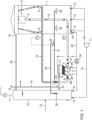
- Figure 1 schematically shows a general set-up of an installation (for use in a process) according to the invention. It schematically shows how an aqueous fluid may be introduced via an inlet (13) into a conditioning tank (12), wherein the aqueous fluid (such as wastewater) undergoes a conditioning step.
- the conditioning tank (12) further comprises an outlet for biogas (17), an outlet for the preconditioned fluid connected to an Influent Distribution System (IDS) (15) at or near the bottom of the bioreactor (1) via a conduit (16).
- the conduit (16) further comprises a recirculation pump (11) for the continuous and controlled recirculation of the fluid.
- the aqueous fluid passes through a sludge bed comprising microorganisms that are capable of converting the biodegradable organic substance into biogas.
- the bioreactor (1) further comprises an internal baffle or deflector/separator (3), located in an upper part of the bioreactor (1) for removing biogas from the gas-aqueous fluid mixture and an outlet for biogas (18).
- the bioreactor (1) further comprises an internal feed conduit (6) with inlet (5) for an aqueous fluid comprising solids from which biogas has been separated that is connected to an inlet (4) of an external separator (2), for the separation of the solids from the liquid phase.
- the inlet (5) of conduit (6) is located under the baffle or deflector (3).
- the conduit (6) additionally comprising a valve (27) for isolating the external separator (2) from the installation in case of maintenance, reparation or replacement of external separator (2).
- Conduit (10) connects the outlet (8) of the external separator (2) with an inlet (9) for fluid enriched in solids from the bioreactor (1), in which conduit biogas injector (23) configured to introduce biogas into the fluid enriched in solids inside the conduit (10) is provided; and a biogas conduit (21) is provided between the biogas injector (23) and the biogas collection hoods inside the bioreactor (22).
- Conduit (10) also comprises a valve (28) for isolation of the external separator (2) from the installation in case of maintenance, reparation or replacement of the external separator (2).
- the biogas conduit (21) in Figure 1 further comprises a T-junction (24) for connecting the biogas conduit (21) to the biogas conduit (26) for introducing biogas, via inlet (25) into the conditioning tank (12) for mixing of the aqueous fluid inside of the conditioning tank.
- Figure 1 further shows means (7) to withdraw and recycle liquid phase from the external separator. It comprises an outlet (7a) to withdraw liquid phase with a reduced biomass content which may be essentially free of biomass) from the separator. From this outlet (7a) a withdrawal conduit (7b) can be provided from which the treated phase can exit the installation, and a recycle line (37) to return liquid phase into the conditioning tank (12).
- the external separator (2) also comprises inlets/outlets (29) connected to the inlet/outlet (31) of the conditioning tank (12) and inlet (32) of the bioreactor (1) via conduit (33).
- This conduit (33) comprises a pump (30) for returning sludge from the external separator to the bioreactor in case this is necessary.
- this conduit (together with isolation valves (27) and (28)) allow for recirculation of an aqueous fluid (usually acidic chemicals) for cleaning in place of the external separator - completely isolated of the reactor and conditioning tank by using the valves (2).
- the installation as shown in Figure 1 , comprises a conduit (20) for biogas connecting an outlet for biogas (18) with an inlet for biogas (19) from the conditioning tank.
- a conduit (20) for biogas connecting an outlet for biogas (18) with an inlet for biogas (19) from the conditioning tank.
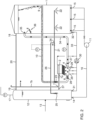
- FIG 2 schematically shows a second set-up of an installation (for use in a process) according to the invention.
- the bioreactor comprises an external feed conduit (34) for feeding an aqueous fluid into the external separator (2).
- a deflector or baffle (36) is located under the inlet (35) of the conduit (34) for directing the aqueous fluid comprising solids into the external feed conduit (34).
- the aqueous fluid treated in a method according to the invention can in principle be any aqueous fluid that comprises an organic substance that is biodegradable, in particular biodegradable under anaerobic conditions.
- the aqueous fluid is selected from the group of municipal waste water, industrial waste water, sewage water, aqueous fluid waste from fermentation processes (such as residual fermentation broth), aqueous slurries and aqueous sludges.
- this may vary in a wide range.
- the water content of the aqueous fluid to be treated is more than 80 wt. %, in particular at least 80 wt. %, more in particular 90 wt.
- the water content is 99.9 wt.% or less, preferably 99.5 wt.% or less, more preferably 99 wt.% or less, in particular 98 wt.% or less, more in particular 96 wt.% or less.
- the total organic substance content of the aqueous fluid to be fed into the bioreactor is usually 0.1 g COD/l or more, preferably in the range of 0.3-100 g COD II, in particular in the range of 5-50 g COD/l.
- aqueous fluids which are particularly suitable to be treated in accordance with the invention are aqueous wastes from a dairy food production or processing (e.g. the production/processing of milk, cheese, butter), a beverage production or processing (e.g. wine, beer, distilled beverage, fruit juice, milk), a biofuel or petrochemical production or processing, a chemical plant, an agricultural facility, a pulp and paper production or processing, a sugar processing or a yeast production.
- a conditioning tank (12) is present in the installation in accordance with the invention.
- aqueous fluid that is to be subjected to a treatment in bioreactor is conditioned for the bioreactor.
- the conditioning tank is not only fed with aqueous fluid that has not been subjected to treatment in the bioreactor yet (raw aqueous feed), but it also receives part of the liquid phase (having reduced biomass content compared to the effluent of the bioreactor) leaving the external separator.
- This liquid phase is excellently suited to condition raw aqueous fluid that newly enters the installation.
- An advantage of using the conditioning tank is that undesired fluctuations in the inflow of aqueous fluid into the bioreactor and undesired fluctuations in the quality of the aqueous fluid can be avoided.
- the recycle from separator to conditioning tank allows for a further improvement in maintaining a relatively constant flow in the various streams between different units of the installation, such as from the conditioning tank to the bioreactor and from bioreactor to external separator. It also offers further robustness, in allowing to keep fluid levels in the units relatively constant, also when there are large fluctuations in supply of aqueous fluid to be treated into the installation.
- the raw aqueous fluid to be treated such as raw wastewater
- specific parameters may be monitored such as temperature and/or pH.
- the skilled person will be able to determine favourable parameter values, dependent on the composition of the biomass. Particularly good results have been achieved with a process wherein the aqueous fluid in the conditioning tank is maintained at or adjusted to a temperature in the range of about 33 to about 37 °C, more preferably in the range of 34 to 36 °C and/or wherein the pH of the aqueous fluid in the conditioning tank may be maintained at or adjusted to a pH in the range of about 6.5 to about 7.2 preferably in the range of 6.6 to 6.8.
- a different temperature or pH may be optimal. E.g., for alkaliphilic bacteria a higher pH may be favored, e.g. up to about pH 11.
- the aqueous fluid preferably after being pre-treated in the conditioning tank, is fed, preferably via an influent distribution system, adapted to provide an at least substantially equal distribution of the aqueous fluid over the horizontal cross section of the bioreactor, into a lower part of an upflow bioreactor where it passes upwards through a sludge bed, comprising biomass, preferably granular biomass.
- the upflow bioreactor is a Granular sludge bed, in particular an expanded granular sludge bed (EGSB), which (E)GSB comprises anaerobic microorganisms and wherein the biodegradable organic substance is converted by the anaerobic micro-organisms, thereby forming the biogas.
- GSSB expanded granular sludge bed
- the bioreactor comprises a consortium of microorganisms comprising at least one type of hydrolytic bacteria, at least one type of acidogenic bacteria, at least one type of acetogenic bacteria and at least one type of methanogenic bacteria.
- biogas can also occur in the inside of the granules, which may cause an upward flotation. At the bottom of the reactor the granules experience a higher pressure and thus biogas is released from the granule and settleability of the sludge is increased.
- the bioreactor is filled up to between 85-98 vol% with the aqueous fluid, preferably up to about 90-95 vol%.
- the gas phase is comprised of biogas that is produced by the microorganisms.
- biogas generally at least substantially consists of methane and carbon dioxide, but additionally may also contain minor amounts of other gasses, such as hydrogen, ammonia, water vapor and/or hydrogen sulfide.
- the aqueous fluid comprises biomass particles and optionally additionally include inorganic and/or organic suspended solids.
- the aqueous fluid further comprises a liquid which usually essentially consists of water and water soluble substances such as organic acids and soluble substances that are not digested by microorganisms or other molecules that are typically present in water, such as minerals or salts.
- the gas-aqueous fluid mixture moves upwards through the reactor where biogas separates from the mixture. This may either occur spontaneously or separation may be enhanced by internal separators.
- the biogas leaves the bioreactor via a biogas outlet located at or near the top of the reactor (above the liquid level). It may leave the bioreactor directly, or may first enter into the upper part of the conditioning tank and exit the installation via an outlet located at or near the top of the tank.
- the biogas is further treated in a manner known per se.
- the biogas may be used to provide energy for the process, i.e. to make the process self-sustainable, for example by heating the system.
- the biogas can be converted to electricity through a generator or upgraded to methane to be transported elsewhere to provide energy for other purposes or as a source for methane for use in a chemical process.
- part of the biogas that is formed is transported from the bioreactor to a lower or middle part of the conditioning tank to improve the mixing of the aqueous fluid in the conditioning tank.
- the bioreactor additionally comprises an internal separator, wherein separation of biogas from an aqueous fluid comprising solids is promoted.
- the internal separator is usually positioned in an upper part of the bioreactor.
- the internal separator preferably is a gas-fluid separator, more preferably a deflector or baffle located in an upper part of the bioreactor.
- the baffle or deflector is preferably located above the feed conduit to the external separator and promotes biogas separation from the aqueous fluid as a result of the natural upflow of biogas or biogas-fluid mixtures.
- the feed conduit to the external separator is an internal feed conduit.
- the internal feed conduit is for at least a substantial part located inside of the bioreactor.
- the inlet for collecting the aqueous fluid from which biogas has been separated is located under the baffle or deflector and collects the aqueous fluid which is then fed into the external separator.
- the feed conduit to the external separator is an external feed conduit.
- the inlet for the aqueous fluid is located on the side of the bioreactor and the external conduit to the external separator is located outside of the bioreactor.
- the bioreactor preferably comprises a baffle or deflector located near the external feed conduit inlet for directing the aqueous fluid into the external feed conduit, preferably located directly under the external feed conduit.
- the internal or external feed conduit feeds the aqueous fluid into an external separator 2 comprising a separation chamber provided with tilted internals for separating the aqueous fluid comprising biomass, and optionally other solids, into a liquid phase and a fluid phase enriched in biomass compared to the aqueous fluid entering the external separator.
- the internal separator is a funnel, preferably a mammoth pump funnel. If a funnel is present the lower part of the funnel is connected to the inlet of the internal feed conduit.
- the funnel promotes an efficient mammoth flow effect thereby aiding separation of biogas from the aqueous fluid (comprising liquids and solids) before the aqueous fluid enters the external separator.
- This gas-fluid separator mammoth pump funnel is preferably comprised by tilted walls shaped as a funnel towards bottom part connects an internal feed conduit.
- the internal separator is a gas-fluid separator comprising tilted internals, preferably tilted plates or tubes.
- the gas-fluid separator is a tilted plate settler.
- the tilted plates cause turbulence inside of the separator, which aids the separation of biogas.
- the tilted plates can be flat or corrugated.
- Such tilted internals promote the separation of biogas from the fluid and solid phases.
- the tilted internals are usually placed at an angle of about 45-65°. Particularly good results have been achieved with placement at an angle of about 55 to about 60°.
- Adjacent internals are typically placed at a distance of at least 2 cm, in particular 2-10 cm distance from each other to enhance separation and avoid clogging of the separator.
- the aqueous fluid enters the internal separator via the upper part of the separator. If a gas-fluid separator comprising tilted internals is present, the inlet of the internal feed conduit is connected to a lower part of the separator for collecting a fluid enriched in solids. The aqueous fluid comprising solids is typically collected at the bottom of the internal separator and fed into an external separator (2).
- the external separator is typically configured such that, during use, the aqueous fluid comprising solids enters via an inlet located in a lower part of the separator.
- the external separator comprises tilted internals to enhance the settleability of the solid particles.
- the tilted plates can be flat or corrugated. Such tilted internals promote the separation of biogas from the liquid and solid phases due to a "lamella effect".
- the tilted internals are usually placed at an angle of about 45-65°. Particularly good results have been achieved with placement at an angle of about 55 to about 60°.
- Adjacent internals are typically placed at a distance of at least 2 cm, in particular 2-10 cm distance from each other to enhance separation and avoid clogging of the separator. from each other to enhance separation and avoid clogging of the separator.
- the use of tilted internals increases settling surface for the settling of solids.
- aqueous fluid passes upwards through the tilted internals where a laminar flow promotes the downward movement of solid particles, whilst allowing liquids to move into the upward direction, where an outlet for an aqueous fluid (effluent) is located.
- This conduit further preferably has a pump (30), preferably a screw pump, for returning sludge to the bioreactor and to circulate chemicals through the external separator. These chemicals may be acidic or basic, depending on the impurity that needs to be removed. This pump allows cleaning in place of the external separator.
- the external separator preferably has an elongated design.
- the liquid phase that leaves the separator is usually essentially free of granular biomass.
- the fluid that is fed into the separator contains suspended solids (in form of debris of granular biomass decay, flocculent - not granulated - biomass, and/or non-degradable suspended material)
- the liquid phase that leaves the separator will have a reduced suspended solids (particularly biomass content) compared to the fed fluid, but may contain residual flocculent biomass.
- this fluid can be purified in a manner known per se , e.g. if the liquid phase is to be taken from the installation to be discarded or put to further use, e.g. as process water.
- Liquid phase that is returned to the bioreactor, e.g. via the conditioning tank, can be returned without needing to remove these suspended solids.
- the system according to the invention comprises a conditioning tank. If a conditioning tank is present, part of the liquid phase, obtained in the external separator may be returned to the conditioning tank to maintain the volume of fluid in the tank at approximately the same level.
- the fluid phase enriched in biomass is re-entered into the bioreactor. It is desired for an efficient process to have a net growth of biomass during the process. During the start-up of the reactor, having a net growth of biomass in the system is important in order to obtain a sufficient amount of biomass for an efficient conversion of biodegradable substance. In a later stage of the process, having a net growth of biomass allows for extraction of sludge from the reactor without negatively affecting the turnover rate, i.e. the conversion of COD. In addition, having excess biomass additionally creates an increase in revenue, since the biomass can be easily stored, transported and sold.
- the return of fluid comprising granular biomass is accomplished without the need of a mechanical pump.
- the upward motion of the biogas in the bioreactor causes a flow that draws the fluid enriched in granular biomass out of the external separator into the bioreactor.
- the installation comprises a biogas injector (23) wherein, during use, biogas from the bioreactor is injected into the conduit for fluids enriched in granular biomass (10) connecting the external separator (2) to the bioreactor (1), to promote the flow of the fluid enriched in granular biomass from the external separator (2) towards the bioreactor (1), see e.g. Figure 1 .
- the aqueous fluid enriched in granular biomass inside of the conduit (10) returns into the bioreactor (1), the returned biogas promotes the upward flow of the aqueous fluid inside of the external separator (2), through a gas lift effect.
- Introducing the biogas into the fluid has as an additional advantage that clogging of the conduits is minimized, preferably prevented.
- the biogas for injection into the conduit (10) is collected from the bioreactor with a biogas collector.
- the biogas collector preferably has one or more biogas collector hoods, which is/are at least during use submerged in the fluid (suspension) in the bioreactor.
- the biogas collector hood(s) (22) is/are positioned below the inlet (9) for fluids enriched in granular biomass from the external separator (2).
- the biogas collector hood(s) (22) is/are positioned below the inlet (5) of conduit (6) or inlet (35) of conduit (34) for the aqueous fluid for external separator (2).
- the invention also relates to an installation comprising an external separator comprising a separation chamber provided with tilted internals, an inlet (4) for feeding the aqueous fluid comprising granular biomass from the bioreactor into a lower part of the external separator.
- the inlet of the external separator is connected to the inlet (5) of the internal feed conduit (6) or the inlet (35) of the external feed conduit (34).
- the aqueous fluid is separated into a liquid phase and a fluid phase enriched in granular biomass.
- the external separator further comprises an outlet (8) for returning an aqueous fluid enriched in granular biomass to the bioreactor, which is connected to the inlet (9) for an aqueous fluid enriched in granular biomass of the bioreactor via a conduit (10).
- Conduit (10) is equipped with a biogas injector (23) for injecting biogas into the fluid enriched in granular biomass, which biogas injector is connected to a biogas collector (22) via a conduit (21).
- a conditioning tank (12) is present from which, during use, aqueous fluid is supplied into the bioreactor.
- a biogas conduit is preferably provided that introduces biogas from the bioreactor into the conditioning tank.
- a recirculation pump is used to generate sufficient upward flow to draw the settled solids from the external separator into the bioreactor.
- the external separator is placed outside of the bioreactor to improve accessibility, thereby facilitating maintenance and start-up procedures and further enables the installation of the reactor in parts, i.e. allowing for an already existing system to be upgraded with an external settler, thereby improving the efficiency of the reactor.
- conduits connecting the external separator with other parts of the installation comprise isolation valves, allowing for the isolation of the external separator and thus facilitating cleaning in place or maintenance of the external separator.
- the pressure in the external separator is higher than the pressure in the upper part of bioreactor. Typically the difference in pressure is between about 1.5-3 bars. The higher pressure compresses the biomass granules thereby removing possible gas that is still present inside of the granule and thus enhancing the settleability of the granules and thus improving removal of solids from the liquid phase.
- At least part of the driving force for the recycle fluid phase enriched in biomass from the external separator to the bioreactor makes use of a gas-lift principle.
- a biogas conduit (21) is provided between the biogas injector (23) into the recycle conduit (10) and the biogas collection hoods inside the bioreactor (22).
- the external separator is preferably placed sufficiently low to allow the recycle conduit (10) to extend upward enough to create the gas lift, ánd return the fluid phase enriched in biomass into a middle or lower part of the bioreactor. This is desired because it is desired to keep the solids content in the upper part of the bioreactor relatively low.
- the external separator is advantageously positioned at or near the floor of the installation or at the same height or below the bottom of the bioreactor, whilst the inlet (9) for the recycled fluid enriched in biomass into the bioreactor (1) via conduit (10) is positioned at a higher level than at least the outlet (8) of fluid enriched in biomass of the external separator, and preferably from at a higher level than the top of the external separator.
- Satisfactory height differences between the outlet (8) of fluid enriched in biomass of the external separator, the gas injector (23) into the recycle conduit (10) and the inlet (9) for recycled fluid enriched in biomass from the external separator can be based on the information disclosed herein, common general knowledge and optionally a limited amount of routine trial and error. In particular, the skilled person will be able to choose height differences such that the pressure differences are such that they drive the fluids/solids/gas in the right direction.
- the conduit for feeding an aqueous fluid from the bioreactor to the external separator is at least substantially straight, i.e. does not contain sharp angles or sharp edges, to prevent sludge from precipitating the conduits, leading to clogging of the system.
Landscapes
- Life Sciences & Earth Sciences (AREA)
- Engineering & Computer Science (AREA)
- Chemical & Material Sciences (AREA)
- Organic Chemistry (AREA)
- Health & Medical Sciences (AREA)
- Microbiology (AREA)
- Zoology (AREA)
- Wood Science & Technology (AREA)
- Bioinformatics & Cheminformatics (AREA)
- Water Supply & Treatment (AREA)
- Hydrology & Water Resources (AREA)
- Environmental & Geological Engineering (AREA)
- Genetics & Genomics (AREA)
- Sustainable Development (AREA)
- Biodiversity & Conservation Biology (AREA)
- Biomedical Technology (AREA)
- Biotechnology (AREA)
- Molecular Biology (AREA)
- Biochemistry (AREA)
- General Engineering & Computer Science (AREA)
- General Health & Medical Sciences (AREA)
- Oil, Petroleum & Natural Gas (AREA)
- General Chemical & Material Sciences (AREA)
- Purification Treatments By Anaerobic Or Anaerobic And Aerobic Bacteria Or Animals (AREA)
- Medicinal Preparation (AREA)
Claims (15)
- Verfahren zur Behandlung eines wässrigen Fluids umfassend eine biologisch abbaubare organische Substanz in einer Anlage, umfassend einen Aufwärtsfluss-Bioreaktor (1), enthaltend ein Granular-Sludge-Bed (GSB), das Granular-Sludge-Bed umfassend körnige Biomasse, und einen externen Abscheider (2), wobei das Verfahren umfasst- die Einspeisung des wässrigen Fluids in einen unteren Teil des Bioreaktors, in Kontakt bringen der eingespeisten Flüssigkeit mit der körnigen Biomasse, wobei die körnige Biomasse anaerobe Mikroorganismen umfasst und wobei die biologisch abbaubare organische Substanz von den anaeroben Mikroorganismen umgewandelt wird, wodurch aus der biologisch abbaubaren organischen Substanz Biogas gebildet wird;- die Entnahme des Fluids, das mit der körnigen Biomasse in Kontakt gebracht worden ist, aus einem oberen Teil des Bioreaktors, das entnommene Fluid umfasst körnige Biomasse; und- die Einspeisung des wässrigen Fluids umfassend die körnige Biomasse, in den externen Abscheider (2), umfassend eine mit geneigten Einbauten versehene Trennkammer, in der sich körnige Biomasse absetzt, wobei in der Trennkammer das die körnige Biomasse umfassende wässrige Fluid in eine flüssige Phase, die einen reduzierten Gehalt an körniger Biomasse hat oder im Wesentlichen frei von körniger Biomasse ist, und eine mit körniger Biomasse angereicherte fluide Phase getrennt wird, wobei die mit körniger Biomasse angereicherte fluide Phase abgesetzte körnige Biomasse umfasst und über eine Leitung (10) und einen Einlass (9) für das mit körniger Biomasse angereicherte Fluid in den Bioreaktor (1) zurückgeführt wird, wobei der externe Abscheider (2) auf gleicher Höhe oder unterhalb des Bodens des Bioreaktors (1) angeordnet ist, während der Einlass (9) für das mit körniger Biomasse angereicherte Fluid in den Bioreaktor (1) über die Leitung (10) auf einem höheren Niveau als mindestens ein Auslass (8) des mit körniger Biomasse angereicherten Fluids des externen Abscheiders (2) angeordnet ist, undwobei Biogas aus dem Bioreaktor durch einen Biogassammler (22) gesammelt wird, der mit einer Biogaseinspritzvorrichtung (23) zum Einspritzen des Biogases in die Leitung (10) zur Rückführung der mit körniger Biomasse angereicherten fluiden Phase aus dem externen Abscheider (2) in den Bioreaktor (1) verbunden ist, wobei das eingespritzte Biogas einen Fluss des mit körniger Biomasse angereicherten Fluids aus dem externen Abscheider (2) in Richtung des Bioreaktors (1) fördert.
- Verfahren nach Anspruch 1, wobei der Bioreaktor ein Expanded-Granular-Sludge-Bed (EGSB) umfasst.
- Verfahren nach einem der vorhergehenden Ansprüche, wobei der Bioreaktor (1) einen internen Gas-Fluid-Abscheider (3) umfasst, angeordnet in einem oberen Teil des Bioreaktors, vorzugsweise einen Gas-Fluid-Abscheider, ausgewählt aus der Gruppe bestehend aus Prallplatten, Umlenkungen, Trichtern und Kippplattenabscheidern.
- Verfahren nach einem der vorhergehenden Ansprüche, wobei der externe Abscheider (2) tiefer als ein Einlass (5) zur Entnahme von wässrigem Fluid aus dem Bioreaktor (1) einer Einspeiseleitung (6) zum Einspeisen des Fluids in den externen Abscheider angeordnet ist.
- Verfahren nach einem der vorhergehenden Ansprüche, wobei das wässrige Fluid zuerst in einem Konditionierungstank (12) behandelt wird, bevor es in den Bioreaktor gelangt, wobei die Behandlung in den Konditionierungstanks vorzugsweise umfasst, Aufrechterhalten des pH-Werts des wässrigen Fluids in dem Konditionierungstank bei oder Anpassen des pH des wässrigen Fluids in dem Konditionierungstank auf einem pH-Wert im Bereich von 6,5 bis 7,2, vorzugsweise im Bereich von 6,6 bis 6,8 und/oder wobei das wässrige Fluid in dem Konditionierungstank auf einer Temperatur im Bereich von 33 bis 37 °C, vorzugsweise im Bereich von 34 bis 36 °C, gehalten oder angepasst wird.
- Anlage zur mikrobiologischen Behandlung eines wässrigen Fluids, umfassend eine biologisch abbaubare organische Substanz, wobei die Anlage umfasst- einen Aufwärtsfluss-Bioreaktor (1) mit Granular-Sludge-Bed (GSB), wobei der Bioreaktor einen Auslass für Biogas umfasst;- einen externen Abscheider (2), wobei der externe Abscheider auf gleicher Höhe oder unterhalb des Bodens des Bioreaktors angeordnet ist, der externe Abscheider umfassend eine Trennkammer, versehen mit geneigten Einbauten, die so angeordnet sind, dass sie eine flüssige Phase von einer fluiden Phase, umfassend körnige Biomasse, trennen, der externe Abscheider umfassend einen Einlass (4) für ein wässriges Fluid, verbunden mit einem Einlass (5) einer Leitung (6) zur Entnahme eines wässrigen Fluids aus dem Bioreaktor (1), einen Auslass (7) für wässriges Fluid, einen Auslass (8) für ein mit körniger Biomasse angereichertes Fluid zu einem Einlass (9) für das mit körniger Biomasse angereicherte Fluid des Bioreaktors (1) über eine Leitung (10), wobei der Einlass (9) für das mit körniger Biomasse angereicherte Fluid in den Bioreaktor (1) über die Leitung (10) auf einem höheren Niveau als zumindest der Auslass (8) des mit körniger Biomasse angereicherten Fluids des externen Abscheiders (2) angeordnet ist;- der Bioreaktor (1) umfasst einen Biogassammler (22), verbunden mit einer Biogaseinspritzvorrichtung (23), konfiguriert, zum Einspritzen von Biogas in die Leitung (10), zum Rückführen des mit Feststoffen angereicherte Fluid aus dem externen Abscheider (2) in den Bioreaktor (1) .
- Anlage nach Anspruch 6, die Anlage außerdem umfassend einen Konditionierungstank (12) zur Vorbehandlung des wässrigen Fluids, umfassend einen Einlass für Abwasser (13), einen Auslass für das wässrige Fluid (14), verbunden über eine Leitung (16) mit einem Einlass (15) des Bioreaktors, und einen Auslass für Biogas.
- Anlage nach Anspruch 6 oder 7, wobei die Anlage ein Zuflussverteilungssystem (15) zum Einleiten des Zuflusses in den Bioreaktor und eine Rückspeisepumpe (11) umfasst, wobei das Zuflussverteilungssystem (15) so angeordnet ist, dass es eine zumindest im Wesentlichen gleichmäßige Verteilung des wässrigen Fluids über die Reaktoroberfläche bereitstellt.
- Anlage nach Anspruch 6, 7 oder 8, wobei der Bioreaktor (1) einen internen Abscheider (3) umfasst, der sich in einem oberen Teil des Bioreaktors befindet und so angeordnet ist, dass er Biogas von einem wässrigen Fluid, umfassend Feststoffe, trennt.
- Anlage nach Anspruch 9, wobei der interne Abscheider (3) ein Gas-Fluid-Abscheider ist, ausgewählt aus der Gruppe bestehend aus Prallplatten, Umlenkungen, Trichtern und Kippplattenabscheidern, vorzugsweise Prallplatten oder Umlenkungen.
- Anlage nach einem der Ansprüche 6 bis 10, wobei der externe Abscheider (2) einen Auslass (29) umfasst, der über eine Leitung (33) mit einem Einlass (32) des Bioreaktors (1) und optional mit einem Einlass (31) eines Konditionierungstanks (12) verbunden ist, wobei die Leitung eine Pumpe (30), vorzugsweise eine Schraubenpumpe, umfasst.
- Anlage nach einem der Ansprüche 6 bis 11, wobei die Leitung (10) ein Ventil (28) und die Leitung (6) ein Ventil (27) zur Isolierung des externen Abscheiders (2) für Wartung, Reinigung oder Austausch umfasst.
- Anlage nach einem der Ansprüche 6 bis 12, wobei der Bioreaktor ein Expanded-Granular-Sludge-Bed-Reaktor ist und/oder wobei die Höhe des Aufstrom-Expanded-Granular-Sludge-Bed-Reaktors, vorzugsweise des Expanded-Granular-Sludge-Bed-Reaktors, etwa zwischen 15 m und 25 mist.
- Anlage nach einem der Ansprüche 6 bis 13, wobei der externe Abscheider auf einem Boden positioniert ist.
- Anlage nach einem der Ansprüche 6 bis 14, wobei der Bioreaktor (1) einen internen Biogassammler (22) umfasst, verbunden mit der Biogaseinspritzvorrichtung (23), konfiguriert, um Biogas in die Leitung (10) zur Rückführung des mit Feststoffen angereicherten Fluids aus dem externen Abscheider (2) in den Bioreaktor (1) einzuspritzen, und wobei die Leitung (10) zur Rückführung des mit Feststoffen angereicherten Fluids mit einem Auslass (9) zur Ableitung des rückgeführten Fluids in den Bioreaktor versehen ist, wobei der Auslass (9) zur Ableitung des rückgeführten Fluids in den Bioreaktor auf einer höheren Höhe als die Biogaseinspritzvorrichtung (23) ist.
Applications Claiming Priority (3)
| Application Number | Priority Date | Filing Date | Title |
|---|---|---|---|
| EP18190286.7A EP3613709A1 (de) | 2018-08-22 | 2018-08-22 | Granulares schlammreaktor-system mit einem externen abscheider |
| EP19755381.1A EP3841071B1 (de) | 2018-08-22 | 2019-08-20 | Granulares schlammreaktor-system mit einem externen lamellenabscheider |
| PCT/EP2019/072296 WO2020038959A1 (en) | 2018-08-22 | 2019-08-20 | Granular sludge reactor system comprising an external separator |
Related Parent Applications (2)
| Application Number | Title | Priority Date | Filing Date |
|---|---|---|---|
| EP19755381.1A Division EP3841071B1 (de) | 2018-08-22 | 2019-08-20 | Granulares schlammreaktor-system mit einem externen lamellenabscheider |
| EP19755381.1A Division-Into EP3841071B1 (de) | 2018-08-22 | 2019-08-20 | Granulares schlammreaktor-system mit einem externen lamellenabscheider |
Publications (2)
| Publication Number | Publication Date |
|---|---|
| EP4119508A1 EP4119508A1 (de) | 2023-01-18 |
| EP4119508B1 true EP4119508B1 (de) | 2024-10-09 |
Family
ID=63592536
Family Applications (3)
| Application Number | Title | Priority Date | Filing Date |
|---|---|---|---|
| EP18190286.7A Withdrawn EP3613709A1 (de) | 2018-08-22 | 2018-08-22 | Granulares schlammreaktor-system mit einem externen abscheider |
| EP22192674.4A Active EP4119508B1 (de) | 2018-08-22 | 2019-08-20 | Granulares schlammreaktor-system mit einem externen abscheider |
| EP19755381.1A Active EP3841071B1 (de) | 2018-08-22 | 2019-08-20 | Granulares schlammreaktor-system mit einem externen lamellenabscheider |
Family Applications Before (1)
| Application Number | Title | Priority Date | Filing Date |
|---|---|---|---|
| EP18190286.7A Withdrawn EP3613709A1 (de) | 2018-08-22 | 2018-08-22 | Granulares schlammreaktor-system mit einem externen abscheider |
Family Applications After (1)
| Application Number | Title | Priority Date | Filing Date |
|---|---|---|---|
| EP19755381.1A Active EP3841071B1 (de) | 2018-08-22 | 2019-08-20 | Granulares schlammreaktor-system mit einem externen lamellenabscheider |
Country Status (12)
| Country | Link |
|---|---|
| US (1) | US11613483B2 (de) |
| EP (3) | EP3613709A1 (de) |
| JP (1) | JP7359841B2 (de) |
| KR (1) | KR102916202B1 (de) |
| CN (1) | CN112888660B (de) |
| DK (2) | DK3841071T3 (de) |
| ES (2) | ES2986320T3 (de) |
| FI (2) | FI4119508T3 (de) |
| HU (2) | HUE067610T2 (de) |
| PL (2) | PL4119508T3 (de) |
| PT (2) | PT4119508T (de) |
| WO (1) | WO2020038959A1 (de) |
Families Citing this family (5)
| Publication number | Priority date | Publication date | Assignee | Title |
|---|---|---|---|---|
| WO2021165541A1 (en) * | 2020-02-21 | 2021-08-26 | Veolia Water Solutions & Technologies Support | Granular sludge reactor system comprising an external separator |
| CN111422981B (zh) * | 2020-04-29 | 2025-08-05 | 谢天宇 | Ic厌氧反应器分阶段反应系统 |
| AU2022234433A1 (en) * | 2021-03-12 | 2023-09-28 | D.C. Water and Sewer Authority | Method and apparatus for multi-deselection in wastewater treatment |
| WO2023147924A1 (en) | 2022-02-04 | 2023-08-10 | Paques I.P. B.V. | Installation for microbiological waste water treatment |
| CN115259556A (zh) * | 2022-07-26 | 2022-11-01 | 上海净豚环保科技有限公司 | 一种造纸废水用厌氧颗粒污泥的增殖培菌方法 |
Family Cites Families (24)
| Publication number | Priority date | Publication date | Assignee | Title |
|---|---|---|---|---|
| DE4042223A1 (de) | 1990-12-29 | 1992-07-02 | Pwa Industriepapier Gmbh | Reaktor und verfahren zur kontinuierlichen mechanischen und anaerob biologischen reinigung feststoffhaltigen abwassers |
| US5514278A (en) | 1993-04-12 | 1996-05-07 | Khudenko; Boris M. | Counterflow microbiological processes |
| DE10005114B4 (de) | 2000-02-07 | 2004-03-18 | Märkl, Herbert, Prof. Dr.-Ing. | Verfahren zur Biomasse-Rückhaltung bei Biogasreaktoren sowie Vorrichtung zur Durchführung des Verfahrens |
| JP2003275788A (ja) | 2002-03-22 | 2003-09-30 | Kurita Water Ind Ltd | 有機性排液の嫌気性消化方法及び嫌気性処理装置 |
| DE50203833D1 (de) * | 2002-10-10 | 2005-09-08 | Va Tech Wabag Gmbh Wien | Reaktor mit Dreiphasen-Trennvorrichtung und Verfahren zur Trennung eines Dreiphasengemisches |
| EP1806323A1 (de) | 2006-01-05 | 2007-07-11 | Biothane Systems International B.V. | Verfahren und Reaktor zur anaerobische Abwasserreinigung |
| JP5303862B2 (ja) | 2007-05-11 | 2013-10-02 | 栗田工業株式会社 | 嫌気性処理方法および嫌気性処理装置 |
| EP2065344A1 (de) * | 2008-09-23 | 2009-06-03 | Paques Bio Systems B.V. | Sedimentieranordnung, Reiniger, die Anordnung und Verfahren zur anaeroben oder aeroben Abwasserreinigung enhalten |
| JP2012000557A (ja) | 2010-06-16 | 2012-01-05 | Mitsubishi Paper Mills Ltd | 嫌気性処理方法及び嫌気性処理装置 |
| EP2404879A1 (de) | 2010-07-08 | 2012-01-11 | Paques IP. B.V. | Reiniger mit einer Feststofftrennungsvorrichtung und Verfahren zur Abwasserreinigung |
| JP5194102B2 (ja) | 2010-12-24 | 2013-05-08 | 株式会社神鋼環境ソリューション | 有機性廃水処理方法ならびに有機性廃水処理装置 |
| EP2641877B1 (de) * | 2012-03-20 | 2016-08-10 | Veolia Water Solutions & Technologies Support | Verfahren zur Behandlung eines Abwasserstroms mithilfe eines Bioreaktors und Membranfilters |
| JP2013220410A (ja) | 2012-04-19 | 2013-10-28 | Sumitomo Heavy Ind Ltd | 嫌気性処理システム及び嫌気性処理方法 |
| JP2014033982A (ja) * | 2012-08-07 | 2014-02-24 | Sumitomo Heavy Ind Ltd | 嫌気性処理システム及び嫌気性処理方法 |
| WO2014104877A2 (en) | 2012-12-24 | 2014-07-03 | Paques I.P. B.V. | Hydrogen sulfide removal from anaerobic treatment |
| WO2014178711A1 (en) * | 2013-05-03 | 2014-11-06 | Paques I.P. B.V. | A process for anaerobic wastewater treatment |
| RU2570546C2 (ru) | 2014-04-18 | 2015-12-10 | Акционерное общество "Компания "ЭКОС" | Способ безотходной биологической очистки сточных вод с переработкой выделенных осадков |
| CN106186300A (zh) * | 2015-05-08 | 2016-12-07 | 廖华平 | 一种用于处理高悬浮固体物料的高负荷复合型厌氧反应器 |
| CN204897526U (zh) * | 2015-08-07 | 2015-12-23 | 廖华平 | 一种用于处理高悬浮固体物料的高负荷复合型厌氧反应器 |
| CN106242047A (zh) * | 2016-08-23 | 2016-12-21 | 北京华夏大禹科技有限公司 | 污水处理厌氧反应系统及水处理方法 |
| CN206014509U (zh) * | 2016-08-27 | 2017-03-15 | 武汉森泰环保股份有限公司 | 一种两相分离内外循环厌氧反应器 |
| CN106673190A (zh) * | 2016-12-22 | 2017-05-17 | 常州大学 | 一种废水高效厌氧处理工艺及装置 |
| EP3724135B1 (de) * | 2017-12-11 | 2026-01-21 | Veolia Water Solutions & Technologies Support | Gleichzeitig phasenbetätigter anaerober sequenzieller batch-reaktor verfahren |
| KR101929861B1 (ko) * | 2018-08-16 | 2018-12-17 | 두산중공업 주식회사 | 입상 활성 슬러지와 막 생물반응기를 포함하는 수처리 시스템 및 이를 이용한 수처리 방법 |
-
2018
- 2018-08-22 EP EP18190286.7A patent/EP3613709A1/de not_active Withdrawn
-
2019
- 2019-08-20 PT PT221926744T patent/PT4119508T/pt unknown
- 2019-08-20 JP JP2021509204A patent/JP7359841B2/ja active Active
- 2019-08-20 ES ES19755381T patent/ES2986320T3/es active Active
- 2019-08-20 CN CN201980069504.XA patent/CN112888660B/zh active Active
- 2019-08-20 KR KR1020217008338A patent/KR102916202B1/ko active Active
- 2019-08-20 DK DK19755381.1T patent/DK3841071T3/da active
- 2019-08-20 PL PL22192674.4T patent/PL4119508T3/pl unknown
- 2019-08-20 DK DK22192674.4T patent/DK4119508T3/da active
- 2019-08-20 HU HUE19755381A patent/HUE067610T2/hu unknown
- 2019-08-20 PL PL19755381.1T patent/PL3841071T3/pl unknown
- 2019-08-20 PT PT197553811T patent/PT3841071T/pt unknown
- 2019-08-20 US US17/270,247 patent/US11613483B2/en active Active
- 2019-08-20 EP EP22192674.4A patent/EP4119508B1/de active Active
- 2019-08-20 EP EP19755381.1A patent/EP3841071B1/de active Active
- 2019-08-20 HU HUE22192674A patent/HUE069675T2/hu unknown
- 2019-08-20 FI FIEP22192674.4T patent/FI4119508T3/fi active
- 2019-08-20 ES ES22192674T patent/ES3004690T3/es active Active
- 2019-08-20 WO PCT/EP2019/072296 patent/WO2020038959A1/en not_active Ceased
- 2019-08-20 FI FIEP19755381.1T patent/FI3841071T3/fi active
Also Published As
| Publication number | Publication date |
|---|---|
| US11613483B2 (en) | 2023-03-28 |
| PL3841071T3 (pl) | 2024-08-12 |
| JP7359841B2 (ja) | 2023-10-11 |
| EP4119508A1 (de) | 2023-01-18 |
| WO2020038959A1 (en) | 2020-02-27 |
| JP2021534958A (ja) | 2021-12-16 |
| EP3841071A1 (de) | 2021-06-30 |
| EP3613709A1 (de) | 2020-02-26 |
| ES2986320T3 (es) | 2024-11-11 |
| PT4119508T (pt) | 2024-12-19 |
| HUE069675T2 (hu) | 2025-04-28 |
| CN112888660A (zh) | 2021-06-01 |
| CN112888660B (zh) | 2024-04-19 |
| FI4119508T3 (fi) | 2024-12-20 |
| PT3841071T (pt) | 2024-07-22 |
| DK4119508T3 (da) | 2025-01-02 |
| KR102916202B1 (ko) | 2026-01-23 |
| US20210331958A1 (en) | 2021-10-28 |
| KR20210056354A (ko) | 2021-05-18 |
| DK3841071T3 (da) | 2024-07-15 |
| ES3004690T3 (en) | 2025-03-12 |
| HUE067610T2 (hu) | 2024-11-28 |
| FI3841071T3 (fi) | 2024-07-04 |
| PL4119508T3 (pl) | 2025-02-17 |
| EP3841071B1 (de) | 2024-04-03 |
Similar Documents
| Publication | Publication Date | Title |
|---|---|---|
| EP4119508B1 (de) | Granulares schlammreaktor-system mit einem externen abscheider | |
| US8043506B2 (en) | Process and reactor for anaerobic waste water purification | |
| US8021552B2 (en) | Process and reactor for anaerobic waste water purification | |
| EP3724135B1 (de) | Gleichzeitig phasenbetätigter anaerober sequenzieller batch-reaktor verfahren | |
| US12509379B2 (en) | Granular sludge reactor system comprising an external separator | |
| RU2804707C2 (ru) | Реакторная система для зернистого ила, содержащая внешний сепаратор | |
| US20250162915A1 (en) | Installation for microbiological waste water treatment |
Legal Events
| Date | Code | Title | Description |
|---|---|---|---|
| PUAI | Public reference made under article 153(3) epc to a published international application that has entered the european phase |
Free format text: ORIGINAL CODE: 0009012 |
|
| STAA | Information on the status of an ep patent application or granted ep patent |
Free format text: STATUS: REQUEST FOR EXAMINATION WAS MADE |
|
| 17P | Request for examination filed |
Effective date: 20220829 |
|
| AC | Divisional application: reference to earlier application |
Ref document number: 3841071 Country of ref document: EP Kind code of ref document: P |
|
| AK | Designated contracting states |
Kind code of ref document: A1 Designated state(s): AL AT BE BG CH CY CZ DE DK EE ES FI FR GB GR HR HU IE IS IT LI LT LU LV MC MK MT NL NO PL PT RO RS SE SI SK SM TR |
|
| STAA | Information on the status of an ep patent application or granted ep patent |
Free format text: STATUS: EXAMINATION IS IN PROGRESS |
|
| 17Q | First examination report despatched |
Effective date: 20230927 |
|
| GRAP | Despatch of communication of intention to grant a patent |
Free format text: ORIGINAL CODE: EPIDOSNIGR1 |
|
| STAA | Information on the status of an ep patent application or granted ep patent |
Free format text: STATUS: GRANT OF PATENT IS INTENDED |
|
| RIC1 | Information provided on ipc code assigned before grant |
Ipc: C02F 103/36 20060101ALN20240227BHEP Ipc: C02F 103/32 20060101ALN20240227BHEP Ipc: C02F 103/28 20060101ALN20240227BHEP Ipc: C02F 3/00 20230101ALN20240227BHEP Ipc: C02F 1/66 20230101ALN20240227BHEP Ipc: C12M 1/00 20060101ALI20240227BHEP Ipc: C12M 1/107 20060101ALI20240227BHEP Ipc: C02F 3/28 20230101AFI20240227BHEP |
|
| RIC1 | Information provided on ipc code assigned before grant |
Ipc: C02F 103/36 20060101ALN20240307BHEP Ipc: C02F 103/32 20060101ALN20240307BHEP Ipc: C02F 3/00 20230101ALN20240307BHEP Ipc: C02F 1/66 20230101ALN20240307BHEP Ipc: C12M 1/00 20060101ALI20240307BHEP Ipc: C12M 1/107 20060101ALI20240307BHEP Ipc: C02F 3/28 20230101AFI20240307BHEP Ipc: C02F 103/28 20060101ALN20240307BHEP |
|
| RIC1 | Information provided on ipc code assigned before grant |
Ipc: C02F 103/36 20060101ALN20240314BHEP Ipc: C02F 103/32 20060101ALN20240314BHEP Ipc: C02F 103/28 20060101ALN20240314BHEP Ipc: C02F 3/00 20230101ALN20240314BHEP Ipc: C02F 1/66 20230101ALN20240314BHEP Ipc: C12M 1/00 20060101ALI20240314BHEP Ipc: C12M 1/107 20060101ALI20240314BHEP Ipc: C02F 3/28 20230101AFI20240314BHEP |
|
| INTG | Intention to grant announced |
Effective date: 20240402 |
|
| GRAS | Grant fee paid |
Free format text: ORIGINAL CODE: EPIDOSNIGR3 |
|
| GRAA | (expected) grant |
Free format text: ORIGINAL CODE: 0009210 |
|
| STAA | Information on the status of an ep patent application or granted ep patent |
Free format text: STATUS: THE PATENT HAS BEEN GRANTED |
|
| AC | Divisional application: reference to earlier application |
Ref document number: 3841071 Country of ref document: EP Kind code of ref document: P |
|
| AK | Designated contracting states |
Kind code of ref document: B1 Designated state(s): AL AT BE BG CH CY CZ DE DK EE ES FI FR GB GR HR HU IE IS IT LI LT LU LV MC MK MT NL NO PL PT RO RS SE SI SK SM TR |
|
| REG | Reference to a national code |
Ref country code: CH Ref legal event code: EP |
|
| REG | Reference to a national code |
Ref country code: DE Ref legal event code: R096 Ref document number: 602019060373 Country of ref document: DE |
|
| REG | Reference to a national code |
Ref country code: IE Ref legal event code: FG4D |
|
| REG | Reference to a national code |
Ref country code: NL Ref legal event code: FP |
|
| REG | Reference to a national code |
Ref country code: PT Ref legal event code: SC4A Ref document number: 4119508 Country of ref document: PT Date of ref document: 20241219 Kind code of ref document: T Free format text: AVAILABILITY OF NATIONAL TRANSLATION Effective date: 20241213 |
|
| REG | Reference to a national code |
Ref country code: FI Ref legal event code: FGE |
|
| REG | Reference to a national code |
Ref country code: DK Ref legal event code: T3 Effective date: 20241220 |
|
| REG | Reference to a national code |
Ref country code: SE Ref legal event code: TRGR |
|
| P01 | Opt-out of the competence of the unified patent court (upc) registered |
Free format text: CASE NUMBER: APP_64653/2024 Effective date: 20241206 |
|
| REG | Reference to a national code |
Ref country code: LT Ref legal event code: MG9D |
|
| REG | Reference to a national code |
Ref country code: ES Ref legal event code: FG2A Ref document number: 3004690 Country of ref document: ES Kind code of ref document: T3 Effective date: 20250312 |
|
| PG25 | Lapsed in a contracting state [announced via postgrant information from national office to epo] |
Ref country code: HR Free format text: LAPSE BECAUSE OF FAILURE TO SUBMIT A TRANSLATION OF THE DESCRIPTION OR TO PAY THE FEE WITHIN THE PRESCRIBED TIME-LIMIT Effective date: 20241009 Ref country code: IS Free format text: LAPSE BECAUSE OF FAILURE TO SUBMIT A TRANSLATION OF THE DESCRIPTION OR TO PAY THE FEE WITHIN THE PRESCRIBED TIME-LIMIT Effective date: 20250209 |
|
| PG25 | Lapsed in a contracting state [announced via postgrant information from national office to epo] |
Ref country code: BG Free format text: LAPSE BECAUSE OF FAILURE TO SUBMIT A TRANSLATION OF THE DESCRIPTION OR TO PAY THE FEE WITHIN THE PRESCRIBED TIME-LIMIT Effective date: 20241009 |
|
| PG25 | Lapsed in a contracting state [announced via postgrant information from national office to epo] |
Ref country code: LV Free format text: LAPSE BECAUSE OF FAILURE TO SUBMIT A TRANSLATION OF THE DESCRIPTION OR TO PAY THE FEE WITHIN THE PRESCRIBED TIME-LIMIT Effective date: 20241009 Ref country code: GR Free format text: LAPSE BECAUSE OF FAILURE TO SUBMIT A TRANSLATION OF THE DESCRIPTION OR TO PAY THE FEE WITHIN THE PRESCRIBED TIME-LIMIT Effective date: 20250110 |
|
| PGFP | Annual fee paid to national office [announced via postgrant information from national office to epo] |
Ref country code: CZ Payment date: 20241223 Year of fee payment: 7 |
|
| REG | Reference to a national code |
Ref country code: HU Ref legal event code: AG4A Ref document number: E069675 Country of ref document: HU |
|
| PG25 | Lapsed in a contracting state [announced via postgrant information from national office to epo] |
Ref country code: RS Free format text: LAPSE BECAUSE OF FAILURE TO SUBMIT A TRANSLATION OF THE DESCRIPTION OR TO PAY THE FEE WITHIN THE PRESCRIBED TIME-LIMIT Effective date: 20250109 |
|
| PG25 | Lapsed in a contracting state [announced via postgrant information from national office to epo] |
Ref country code: SM Free format text: LAPSE BECAUSE OF FAILURE TO SUBMIT A TRANSLATION OF THE DESCRIPTION OR TO PAY THE FEE WITHIN THE PRESCRIBED TIME-LIMIT Effective date: 20241009 |
|
| REG | Reference to a national code |
Ref country code: DE Ref legal event code: R097 Ref document number: 602019060373 Country of ref document: DE |
|
| PG25 | Lapsed in a contracting state [announced via postgrant information from national office to epo] |
Ref country code: EE Free format text: LAPSE BECAUSE OF FAILURE TO SUBMIT A TRANSLATION OF THE DESCRIPTION OR TO PAY THE FEE WITHIN THE PRESCRIBED TIME-LIMIT Effective date: 20241009 |
|
| PG25 | Lapsed in a contracting state [announced via postgrant information from national office to epo] |
Ref country code: RO Free format text: LAPSE BECAUSE OF FAILURE TO SUBMIT A TRANSLATION OF THE DESCRIPTION OR TO PAY THE FEE WITHIN THE PRESCRIBED TIME-LIMIT Effective date: 20241009 |
|
| PG25 | Lapsed in a contracting state [announced via postgrant information from national office to epo] |
Ref country code: SK Free format text: LAPSE BECAUSE OF FAILURE TO SUBMIT A TRANSLATION OF THE DESCRIPTION OR TO PAY THE FEE WITHIN THE PRESCRIBED TIME-LIMIT Effective date: 20241009 |
|
| PLBE | No opposition filed within time limit |
Free format text: ORIGINAL CODE: 0009261 |
|
| STAA | Information on the status of an ep patent application or granted ep patent |
Free format text: STATUS: NO OPPOSITION FILED WITHIN TIME LIMIT |
|
| PGFP | Annual fee paid to national office [announced via postgrant information from national office to epo] |
Ref country code: NL Payment date: 20250821 Year of fee payment: 7 |
|
| 26N | No opposition filed |
Effective date: 20250710 |
|
| PGFP | Annual fee paid to national office [announced via postgrant information from national office to epo] |
Ref country code: HU Payment date: 20250814 Year of fee payment: 7 |
|
| PGFP | Annual fee paid to national office [announced via postgrant information from national office to epo] |
Ref country code: ES Payment date: 20250917 Year of fee payment: 7 Ref country code: FI Payment date: 20250820 Year of fee payment: 7 Ref country code: PT Payment date: 20250807 Year of fee payment: 7 |
|
| PGFP | Annual fee paid to national office [announced via postgrant information from national office to epo] |
Ref country code: DK Payment date: 20250821 Year of fee payment: 7 Ref country code: DE Payment date: 20250819 Year of fee payment: 7 |
|
| PGFP | Annual fee paid to national office [announced via postgrant information from national office to epo] |
Ref country code: NO Payment date: 20250820 Year of fee payment: 7 |
|
| PGFP | Annual fee paid to national office [announced via postgrant information from national office to epo] |
Ref country code: PL Payment date: 20250808 Year of fee payment: 7 Ref country code: TR Payment date: 20250812 Year of fee payment: 7 Ref country code: IT Payment date: 20250829 Year of fee payment: 7 |
|
| REG | Reference to a national code |
Ref country code: AT Ref legal event code: UEP Ref document number: 1730453 Country of ref document: AT Kind code of ref document: T Effective date: 20241009 |
|
| PGFP | Annual fee paid to national office [announced via postgrant information from national office to epo] |
Ref country code: BE Payment date: 20250825 Year of fee payment: 7 Ref country code: GB Payment date: 20250825 Year of fee payment: 7 |
|
| PGFP | Annual fee paid to national office [announced via postgrant information from national office to epo] |
Ref country code: AT Payment date: 20250819 Year of fee payment: 7 Ref country code: FR Payment date: 20250827 Year of fee payment: 7 |
|
| PGFP | Annual fee paid to national office [announced via postgrant information from national office to epo] |
Ref country code: CH Payment date: 20250901 Year of fee payment: 7 Ref country code: SE Payment date: 20250821 Year of fee payment: 7 |
|
| PGFP | Annual fee paid to national office [announced via postgrant information from national office to epo] |
Ref country code: IE Payment date: 20250821 Year of fee payment: 7 |
|
| PGFP | Annual fee paid to national office [announced via postgrant information from national office to epo] |
Ref country code: CY Payment date: 20250808 Year of fee payment: 7 |